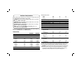
1
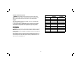
INSTRUCTION MANUAL
DCD936-XE, DCD985-XE
13 mm (1/2") CORDLESS DRILL/DRIVER/HAMMERDRILL
Definitions: Safety Guidelines
The definitions below describe the level of severity for each signal word. Please
read the manual and pay attention to these symbols.
DANGER: Indicates an imminently hazardous situation which, if not avoided,
will result in death or serious injury.
WARNING: Indicates a potentially hazardous situation which, if not avoided,
could result in death or serious injury.
CAUTION: Indicates a potentially hazardous situation which, if not avoided,
may result in minor or moderate injury.
NOTICE: indicates a practice not related to personal injury which, if not
avoided, may result in property damage.
Technical Data
W
DCD936-XE
14.4
Li-Ion
350
DCD985-XE
18
Li-Ion
500
min-1
min-1
min-1
0–450
0–1200
0–1800
0–575
0–1350
0–2000
min-1
min-1
min-1
Nm
mm
0–7650
0–20400
0–30600
72/35
13
0–9775
0–22900
0–34000
80/38
13
VDC
mm
mm
mm
kg
45
13
14
1.77
50
13
16
1.77
LPA (sound pressure)
KPA (sound pressure uncertainty)
LWA (sound power)
KWA (sound power uncertainty)
dB(A)
dB(A)
dB(A)
dB(A)
90
3
101
3
90
3
101
3
Vibration total values (triax vector sum) determined according to EN 60745:
Vibration emission value ah
Drilling into metal
ah,D =
m/s²
< 2.5
< 2.5
Uncertainty K =
m/s²
1.5
1.5
Vibration emission value ah
Impact drilling
ah,ID =
m/s²
11.0
11.0
Uncertainty K =
m/s²
1.5
1.5
Vibration emission value ah
Screwdriving
ah =
m/s²
< 2.5
< 2.5
Uncertainty K =
m/s²
1.5
1.5
IF YOU HAVE ANY QUESTIONS OR COMMENTS ABOUT THIS OR ANY DEWALT TOOL,
CALL US AT: 1800 444 224 (Aust) or 0800 339 258 (NZ).
Voltage
Battery Type
Power output
No-load speed
1st gear
2nd gear
3rd gear
Impact rate
1st gear
2nd gear
3rd gear
Max. torque (hard/soft)
Chuck capacity
Maximum drilling capacity
Wood
Metal
Masonry
Weight (without battery pack)
The vibration emission level given in this information sheet has been measured in
accordance with a standardised test given in EN 60745 and may be used to compare
one tool with another. It may be used for a preliminary assessment of exposure.
WARNING: The declared vibration emission level represents the main applications
of the tool. However if the tool is used for different applications, with different
accessories or poorly maintained, the vibration emission may differ. This may
significantly increase the exposure level over the total working period.
1
An estimation of the level of exposure to vibration should also take into account
the times when the tool is switched off or when it is running but not actually doing
the job. This may significantly reduce the exposure level over the total working
period.
2) ELECTRICAL SAFETY
a) Power tool plugs must match the outlet. Never modify the plug in any
way. Do not use any adapter plugs with earthed (grounded) power tools.
Unmodified plugs and matching outlets will reduce risk of electric shock.
b) Avoid body contact with earthed or grounded surfaces such as pipes,
radiators, ranges and refrigerators. There is an increased risk of electric
shock if your body is earthed or grounded.
c) Do not expose power tools to rain or wet conditions. Water entering a power
tool will increase the risk of electric shock.
d) Do not abuse the cord. Never use the cord for carrying, pulling or
unplugging the power tool. Keep cord away from heat, oil, sharp edges
or moving parts. Damaged or entangled cords increase the risk of electric
shock.
e) When operating a power tool outdoors, use an extension cord suitable
for outdoor use. Use of a cord suitable for outdoor use reduces the risk of
electric shock.
f) If operating a power tool in a damp location is unavoidable, use a residual
current device (RCD) protected supply. Use of an RCD reduces the risk of
electric shock.
3) PERSONAL SAFETY
a) Stay alert, watch what you are doing and use common sense when
operating a power tool. Do not use a power tool while you are tired or
under the influence of drugs, alcohol or medication. A moment of inattention
while operating power tools may result in serious personal injury.
b) Use personal protective equipment. Always wear eye protection. Protective
equipment such as dust mask, non-skid safety shoes, hard hat, or hearing
protection used for appropriate conditions will reduce personal injuries.
c) Prevent unintentional starting. Ensure the switch is in the off position
before connecting to power source and/or battery pack, picking up or
carrying the tool. Carrying power tools with your finger on the switch or
energising power tools that have the switch on invites accidents.
d) Remove any adjusting key or wrench before turning the power tool on. A
wrench or a key left attached to a rotating part of the power tool may result in
personal injury.
Identify additional safety measures to protect the operator from the effects of
vibration such as: maintain the tool and the accessories, keep the hands warm,
organisation of work patterns.
SAFETY INSTRUCTIONS FOR POWER TOOLS
When using power tools, always observe the safety regulations applicable in your
country to reduce the risk of fire, electric shock and personal injury. Read the following
safety instructions before attempting to operate this product. Keep these instructions in
a safe place.
WARNING: To reduce the risk of injury, user must read the instruction manual.
GENERAL POWER TOOL SAFETY WARNINGS
WARNING! Read all safety warnings and all instructions Failure to follow
the warnings and instructions may result in electric shock, fire and/or serious
injury.
SAVE ALL WARNINGS AND INSTRUCTIONS FOR
FUTURE REFERENCE
The term “power tool” in the warnings refers to your mains-operated (corded) power
tool or battery-operated (cordless) power tool.
1) WORK AREA SAFETY
a) Keep work area clean and well lit. Cluttered or dark areas invite accidents.
b) Do not operate power tools in explosive atmospheres, such as in the
presence of flammable liquids, gases or dust. Power tools create sparks
which may ignite the dust or fumes.
c) Keep children and bystanders away while operating a power tool.
Distractions can cause you to lose control.
2
e) Do not overreach. Keep proper footing and balance at all times. This
enables better control of the power tool in unexpected situations.
f) Dress properly. Do not wear loose clothing or jewellery. Keep your hair,
clothing and gloves away from moving parts. Loose clothes, jewellery or
long hair can be caught in moving parts.
g) If devices are provided for the connection of dust extraction and collection
facilities, ensure these are connected and properly used. Use of dust
collection can reduce dust-related hazards.
4) POWER TOOL USE AND CARE
a) Do not force the power tool. Use the correct power tool for your
application. The correct power tool will do the job better and safer at the rate
for which it was designed.
b) Do not use the power tool if the switch does not turn it on and off. Any
power tool that cannot be controlled with the switch is dangerous and must
be repaired.
c) Disconnect the plug from the power source and/or the battery pack from
the power tool before making any adjustments, changing accessories,
or storing power tools. Such preventive safety measures reduce the risk of
starting the power tool accidentally.
d) Store idle power tools out of the reach of children and do not allow
persons unfamiliar with the power tool or these instructions to operate the
power tool. Power tools are dangerous in the hands of untrained users.
e) Maintain power tools. Check for misalignment or binding of moving parts,
breakage of parts and any other condition that may affect the power tool’s
operation. If damaged, have the power tool repaired before use. Many
accidents are caused by poorly maintained power tools.
f) Keep cutting tools sharp and clean. Properly maintained cutting tools with
sharp cutting edges are less likely to bind and are easier to control.
g) Use the power tool, accessories and tool bits, etc. in accordance with
these instructions, taking into account the working conditions and the work
to be performed. Use of the power tool for operations different from those
intended could result in a hazardous situation.
5) BATTERY TOOL USE AND CARE
a) Recharge only with the charger specified by the manufacturer. A charger
that is suitable for one type of battery pack may create a risk of fire when
used with another battery pack.
b) Use power tools only with specifically designated battery packs. Use of any
other battery packs may create a risk of injury and fire.
c) When battery pack is not in use, keep it away from other metal objects like
paper clips, coins, keys, nails, screws, or other small metal objects that
can make a connection from one terminal to another. Shorting the battery
terminals together may cause burns or a fire.
d) Under abusive conditions, liquid may be ejected from the battery; avoid
contact. If contact accidentally occurs, flush with water. If liquid contacts
eyes, additionally seek medical help. Liquid ejected from the battery may
cause irritation or burns.
6) SERVICE
a) Have your power tool serviced by a qualified repair person using only
identical replacement parts. This will ensure that the safety of the power tool
is maintained.
Electrical Safety
The electric motor has been designed for one voltage range only. Always check that
the power supply corresponds to the voltage on the rating plate. 220–240 V AC
means your tool will operate on alternating current. Operation at a voltage outside this
range can cause loss of power and can result in overheating. All DEWALT tools are
factory tested; if this tool does not operate, check the power supply. Your DEWALT
tool is double insulated, therefore no earth wire is required.
• Young children and the infirm. This appliance is not intended for use by young
children or infirm persons without supervision.
– This appliance is not intended for use by persons (including children) with
reduced physical, sensory or mental capabilities, or lack of experience and
knowledge, unless they have been given supervision or instruction concerning
use of the appliance by a person responsible for their safety.
– Children should be supervised to ensure that they do not play with the appliance.
3
• Replacement of the supply cord. If the supply cord or plug is damaged, it must
be replaced by the manufacturer or an authorised DEWALT Service Centre in
order to avoid a hazard.
• Air vents often cover moving parts and should be avoided. Loose clothes,
jewellery or long hair can be caught in moving parts.
WARNING: We recommend the use of a residual current device with a residual
current rating of 30mA or less.
WARNING: ALWAYS wear approved protective safety equipment complying with
the following standards:
• Eye protection: AS/NZS1337 Eye Protectors for Industrial Applications;
• Hearing protection: AS/NZS1270 Acoustics – Hearing Protection;
• Respiratory protection: AS/NZS1716 Respiratory Protective Devices.
WARNING: Some dust created by power sanding, sawing, grinding, drilling, and
other construction activities contains chemicals known to cause cancer, birth defects
or other reproductive harm. Some examples of these chemicals are:
• lead from lead-based paints,
• crystalline silica from bricks and cement and other masonry products, and
• arsenic and chromium from chemically-treated lumber.
Your risk from these exposures varies, depending on how often you do this type of
work. To reduce your exposure to these chemicals: work in a well ventilated area, and
work with approved safety equipment, such as those dust masks that are specially
designed to filter out microscopic particles.
• Avoid prolonged contact with dust from power sanding, sawing, grinding,
drilling, and other construction activities. Wear protective clothing and wash
exposed areas with soap and water. Allowing dust to get into your mouth, eyes,
or lay on the skin may promote absorption of harmful chemicals.
WARNING: Use of this tool can generate and/or disburse dust, which may cause
serious and permanent respiratory or other injury. Always use approved respiratory
protection appropriate for the dust exposure. Direct particles away from face and
body.
WARNING: Always wear proper personal hearing protection that conforms to
AS/NZS1270 during use. Under some conditions and duration of use, noise from this
product may contribute to hearing loss.
CAUTION: When not in use, place tool on its side on a stable surface where it
will not cause a tripping or falling hazard. Some tools with large battery packs will
stand upright on the battery pack but may be easily knocked over.
Extension Cords
CAUTION: Use only extension cords that are approved by the country’s Electrical
Authority. Before using extension cords, inspect them for loose or exposed wires,
damaged insulation and defective fittings. Replace the cord if necessary.
Drill/Driver/Hammerdrill Safety Warnings
• Wear ear protectors when impact drilling. Exposure to noise can cause hearing
loss.
• Use auxiliary handle(s), if supplied with the tool. Loss of control can cause
personal injury.
• Hold power tool by insulated gripping surfaces, when performing an operation
where the cutting accessory may contact hidden wiring. Cutting accessory
contacting a “live” wire may make exposed metal parts of the power tool “live”
and could give the operator an electric shock.
• Use clamps or other practical way to secure and support the workpiece to a
stable platform. Holding the work by hand or against your body is unstable and
may lead to loss of control.
• Wear safety goggles or other eye protection. Hammering and drilling operations
cause chips to fly. Flying particles can cause permanent eye damage.
• Always use the side handle supplied with the tool. Keep a firm grip on the tool
at all times. Do not attempt to operate this tool without holding it with both
hands. Operating this tool with one hand will result in loss of control. Breaking
through or encountering hard materials such as re-bar may be hazardous as well.
• Accessories and tool may get hot during operation. Wear gloves when handling
them if performing heat producing applications such as hammerdrilling and
drilling metals.
• Do not operate this tool for long periods of time. Vibration caused by hammer
action may be harmful to your hands and arms. Use gloves to provide extra
cushion and limit exposure by taking frequent rest periods.
4
• The label on your tool may include the following symbols. The symbols and their
definitions are as follows:
V ................. volts
A ...............amperes
Hz ............... hertz
W ..............watts
min ............. minutes
...........alternating current
........ direct current
...........alternating or direct current
no ..............no load speed
.............. Class I Construction
................... (grounded)
n................rated speed
.............. Class II Construction
.............earthing terminal
................... (double insulated)
..............safety alert symbol
…/min ........ per minute
BPM ..........beats per minute
IPM ............. impacts per minute
RPM ..........revolutions per minute
SPM ............ strokes per minute
sfpm ..........surface feet per minute
• DO NOT splash or immerse in water or other liquids.
• Do not store or use the tool and battery pack in locations where the
temperature may reach or exceed 40 °C (105 °F) (such as outside sheds
or metal buildings in summer). For best life store battery packs in a cool, dry
location.
NOTE: Do not store the battery packs in a tool with the trigger switch locked
on. Never tape the trigger switch in the ON position.
WARNING: Fire hazard. Never attempt to open the battery pack for any reason. If
the battery pack case is cracked or damaged, do not insert into the charger. Do not
crush, drop or damage the battery pack. Do not use a battery pack or charger that
has received a sharp blow, been dropped, run over or damaged in any way (e.g.,
pierced with a nail, hit with a hammer, stepped on). Damaged battery packs should be
returned to the service center for recycling.
WARNING: Fire hazard. Do not store or carry the battery pack so that metal
objects can contact exposed battery terminals. For example, do not place the
battery pack in aprons, pockets, tool boxes, product kit boxes, drawers, etc., with
loose nails, screws, keys, etc. Transporting batteries can possibly cause fires if
the battery terminals inadvertently come in contact with conductive materials
such as keys, coins, hand tools and the like. The US Department of Transportation
Hazardous Material Regulations (HMR) actually prohibit transporting batteries in
commerce or on airplanes (e.g., packed in suitcases and carry-on luggage) UNLESS
they are properly protected from short circuits. So when transporting individual
battery packs, make sure that the battery terminals are protected and well insulated
from materials that could contact them and cause a short circuit.
SPECIFIC SAFETY INSTRUCTIONS FOR LITHIUM ION (Li-Ion)
• Do not incinerate the battery pack even if it is severely damaged or is
completely worn out. The battery pack can explode in a fire. Toxic fumes and
materials are created when lithium ion battery packs are burned.
• If battery contents come into contact with the skin, immediately wash area
with mild soap and water. If battery liquid gets into the eye, rinse water over the
open eye for 15 minutes or until irritation ceases. If medical attention is needed,
the battery electrolyte is composed of a mixture of liquid organic carbonates and
lithium salts.
SAVE ALL WARNINGS AND INSTRUCTIONS FOR
FUTURE REFERENCE
Important Safety Instructions for All Battery Packs
When ordering replacement battery packs, be sure to include the catalog number and
voltage. Consult the chart at the end of this manual for compatibility of chargers and
battery packs.
The battery pack is not fully charged out of the carton. Before using the battery pack
and charger, read the safety instructions below and then follow charging procedures
outlined.
READ ALL INSTRUCTIONS
• Do not charge or use the battery pack in explosive atmospheres, such as in
the presence of flammable liquids, gases or dust. Inserting or removing the
battery pack from the charger may ignite the dust or fumes.
• NEVER force the battery pack into the charger. DO NOT modify the battery
pack in any way to fit into a non-compatible charger as battery pack may
rupture causing serious personal injury. Consult the chart at the end of this
manual for compatibility of batteries and chargers.
• Charge the battery packs only in designated DEWALT chargers.
5
• Contents of opened battery cells may cause respiratory irritation. Provide fresh
air. If symptoms persist, seek medical attention.
WARNING: Burn hazard. Battery liquid may be flammable if exposed to spark or
flame.
• When operating a charger outdoors, always provide a dry location and use an
extension cord suitable for outdoor use. Use of a cord suitable for outdoor use
reduces the risk of electric shock.
• Do not place any object on top of the charger or place the charger on a soft
surface that might block the ventilation slots and result in excessive internal
heat. Place the charger in a position away from any heat source. The charger is
ventilated through slots in the top and the bottom of the housing.
• Do not operate the charger with a damaged cord or plug.
• Do not operate the charger if it has received a sharp blow, been dropped or
otherwise damaged in any way. Take it to an authorized service center.
• Do not disassemble the charger; take it to an authorized service center when
service or repair is required. Incorrect reassembly may result in a risk of electric
shock, electrocution or fire.
• Disconnect the charger from the outlet before attempting any cleaning. This
will reduce the risk of electric shock. Removing the battery pack will not reduce
this risk.
• NEVER attempt to connect 2 chargers together.
• The charger is designed to operate on standard 230 V household electrical
power. Do not attempt to use it on any other voltage. This does not apply to the
vehicular charger.
Important Safety Instructions for All Battery Chargers
SAVE THESE INSTRUCTIONS: This manual contains important safety and operating
instructions for battery chargers.
• Before using the charger, read all instructions and cautionary markings on the
charger, battery pack and product using the battery pack.
WARNING: Shock hazard. Do not allow any liquid to get inside the charger. Electric
shock may result.
CAUTION: Burn hazard. To reduce the risk of injury, charge only DEWALT
rechargeable battery packs. Other types of batteries may overheat and burst resulting
in personal injury and property damage.
NOTICE: Under certain conditions, with the charger plugged into the power supply, the
charger can be shorted by foreign material. Foreign materials of a conductive nature,
such as, but not limited to, grinding dust, metal chips, steel wool, aluminum foil or any
buildup of metallic particles should be kept away from the charger cavities. Always
unplug the charger from the power supply when there is no battery pack in the cavity.
Unplug the charger before attempting to clean.
• DO NOT attempt to charge the battery pack with any chargers other than the
ones in this manual. The charger and battery pack are specifically designed to
work together.
• These chargers are not intended for any uses other than charging DEWALT
rechargeable batteries. Any other uses may result in risk of fire, electric shock
or electrocution.
• Do not expose the charger to rain or snow.
• Pull by the plug rather than the cord when disconnecting the charger. This will
reduce the risk of damage to the electric plug and cord.
• Make sure that the cord is located so that it will not be stepped on, tripped
over or otherwise subjected to damage or stress.
• Do not use an extension cord unless it is absolutely necessary. Use
of improper extension cord could result in risk of fire, electric shock or
electrocution.
Chargers
Your tool uses a DEWALT charger. Be sure to read all safety instructions before using
your charger. Consult the chart at the end of this manual for compatibility of chargers
and battery packs.
Charging Procedure (Fig. 1)
1. Plug the charger into an appropriate outlet before inserting the battery pack.
2. Insert the battery pack (I) into the charger, as shown in Figure 1, making sure the
pack is fully seated in charger. The red (charging) light will blink continuously,
indicating that the charging process has started.
3. The completion of charge will be indicated by the red light remaining ON
continuously. The pack is fully charged and may be used at this time or left in the
charger.
6
FIG. 1
HOT/COLD DELAY
This charger has a hot/cold delay feature: when the charger detects a battery that is
hot, it automatically starts a delay, suspending charging until the battery has cooled.
After the battery has cooled, the charger automatically switches to the pack charging
mode. This feature ensures maximum battery life. The red light flashes long, then
short while in the hot/cold delay mode.
LEAVING THE BATTERY PACK IN THE CHARGER
The charger and battery pack can be left connected with the charge indicator showing
Pack Charged.
I
WEAK BATTERY PACKS: Weak batteries will continue to function but should not be
expected to perform as much work.
FAULTY BATTERY PACKS: This charger will not charge a faulty battery pack. The
charger will indicate faulty battery pack by refusing to light or by displaying problem pack
or charger.
NOTE: This could also mean a problem with a charger.
Indicator Light Operation
PACK CHARGING
PROBLEM POWERLINE
Some chargers have a problem powerline indicator. When the charger is used with
some portable power sources such as generators or sources that convert DC to AC, the
charger may temporarily suspend operation, flashing the red light with two fast blinks
followed by a pause. This indicates the power source is out of limits.
PACK CHARGED
HOT/COLD DELAY
x
PROBLEM PACK OR CHARGER
Important Charging Notes
1. Longest life and best performance can be obtained if the battery pack is charged
when the air temperature is between 18 ° – 24 °C (65 °F and 75 °F). DO NOT
charge the battery pack in an air temperature below +4 °C (+40 °F), or above
+40 °C (+105 °F). This is important and will prevent serious damage to the
battery pack.
2. The charger and battery pack may become warm to the touch while charging.
This is a normal condition, and does not indicate a problem. To facilitate the
cooling of the battery pack after use, avoid placing the charger or battery pack in
a warm environment such as in a metal shed or an uninsulated trailer.
3. A cold battery pack will charge at about half the rate of a warm battery pack. The
battery pack will charge at that slower rate throughout the entire charging cycle
and will not return to maximum charge rate even if the battery pack warms.
PROBLEM POWERLINE
Charge Indicators
This charger is designed to detect certain problems that can arise. Problems are
indicated by the red light flashing at a fast rate. If this occurs, re-insert the battery pack
into the charger. If the problem persists, try a different battery pack to determine if the
charger is working properly. If the new pack charges correctly, then the original pack is
defective and should be returned to a service center or other collection site for recycling.
If the new battery pack elicits the same trouble indication as the original, have the
charger and the battery pack tested at an authorized service center.
7
COMPONENTS (FIG. 2)
4. If the battery pack does not charge properly:
a. Check operation of receptacle by plugging in a lamp or other appliance;
b. Check to see if receptacle is connected to a light switch which turns power off
when you turn out the lights;
c. Move the charger and battery pack to a location where the surrounding air
temperature is approximately 18 ° – 24 °C (65 °F and 75 °F);
d. If charging problems persist, take the tool, battery pack and charger to your
local service center.
5. The battery pack should be recharged when it fails to produce sufficient power
on jobs which were easily done previously. DO NOT CONTINUE to use under
these conditions. Follow the charging procedure. You may also charge a partially
used pack whenever you desire with no adverse effect on the battery pack.
6. Foreign materials of a conductive nature such as, but not limited to, grinding dust,
metal chips, steel wool, aluminum foil, or any buildup of metallic particles should
be kept away from charger cavities. Always unplug the charger from the power
supply when there is no battery pack in the cavity. Unplug the charger before
attempting to clean.
7. Do not freeze or immerse the charger in water or any other liquid.
WARNING: Shock hazard. Don’t allow any liquid to get inside the charger. Electric
shock may result.
WARNING: Burn hazard. Do not submerge the battery pack in any liquid or allow
any liquid to enter the battery pack. Never attempt to open the battery pack for any
reason. If the plastic housing of the battery pack breaks or cracks, return to a service
center for recycling.
WARNING: Never modify the power tool or any part of it. Damage or personal
injury could result.
A. Trigger switch
H. Side handle
B. Forward/reverse control button
I. Battery pack
C. Worklight
J. Battery release button
D. Chuck
K. Belt hook
E. Torque adjustment collar
L. Mounting screw
F. Mode control collar
M. Bit clip
G. Gear shifter
FIG. 2
E
F
G
D
C
M
B
Storage Recommendations
1. The best storage place is one that is cool and dry, away from direct sunlight and
excess heat or cold.
2. For long storage, it is recommended to store a fully charged battery pack in a
cool dry place out of the charger for optimal results.
NOTE: Battery packs should not be stored completely depleted of charge. The battery
pack will need to be recharged before use.
A
H
J
I
SAVE ALL WARNINGS AND INSTRUCTIONS FOR
FUTURE REFERENCE
8
J
L
K
INTENDED USE
These drills/drivers/hammerdrills are designed for professional drilling, percussion
drilling and screwdriving applications.
DO NOT use under wet conditions or in presence of flammable liquids or gases.
These drills/drivers/hammerdrills are professional power tools. DO NOT let children
come into contact with the tool. Supervision is required when inexperienced operators
use this tool.
The center position of the control button locks the tool in the off position. When
changing the position of the control button, be sure the trigger is released.
NOTE: The first time the tool is run after changing the direction of rotation, you may hear
a click on start up. This is normal and does not indicate a problem.
Worklight (Fig. 2)
There is a worklight (C) located just above the trigger switch (A). The worklight
is activated when the trigger switch is depressed, and will automatically turn
off 20 seconds after the trigger switch is released. If the trigger switch remains
depressed, the worklight will remain on.
NOTE: The worklight is for lighting the immediate work surface and is not intended to
be used as a flashlight.
Variable Speed Trigger Switch (Fig. 2)
To turn the tool on, squeeze the trigger switch (A). To turn the tool off, release the
trigger switch. Your tool is equipped with a brake. The chuck will stop as soon as the
trigger switch is fully released.
NOTE: Continuous use in variable speed range is not recommended. It may damage
the switch and should be avoided.
ASSEMBLY AND ADJUSTMENTS
WARNING: To reduce the risk of serious personal injury, place the forward/
reverse button in the lock-off position or turn tool off and disconnect battery pack
before making any adjustments or removing/installing attachments or accessories.
An accidental start-up can cause injury.
Side Handle (Fig. 2)
WARNING: To reduce the risk of personal injury, ALWAYS operate the tool with the
side handle properly installed. Failure to do so may result in the side handle slipping
during tool operation and subsequent loss of control. Hold tool with both hands to
maximize control.
Side handle (H) clamps to the front of the gear case and may be rotated 360° to permit
right- or left-hand use. Side handle must be tightened sufficiently to resist the twisting
action of the tool if the accessory binds or stalls. Be sure to grip the side handle at
the far end to control the tool during a stall.
If model is not equipped with side handle, grip drill with one hand on the handle and one
hand on the battery pack.
NOTE: Side handle comes equipped on the DCD985-XE.
Mode Control Collar (Fig. 3–5)
Your drill is equipped with a separate mode control collar (F) to switch between
drilling, screwdriving and hammerdrilling mode.
DRILLING (FIG. 3)
CAUTION: When the mode collar is in the drill/hammerdrill mode, the drill will not
clutch out regardless of the position of the torque adjustment collar (E).
Rotate the mode control collar (F) so the drill symbol is aligned with the arrow.
NOTE: The torque adjustment collar (E) may be set on any number.
Forward/Reverse Control Button (Fig. 2)
SCREWDRIVING (FIG. 4)
Rotate the mode control collar (F) so the screw symbol is aligned with the arrow.
NOTE: The torque adjustment collar may be set to any number at any time. However,
the torque adjustment collar is only engaged during screwdriving mode and not in drill
and hammerdrill modes.
A forward/reverse control button (B) determines the direction of the tool and also
serves as a lock-off button.
To select forward rotation, release the trigger switch and depress the forward/reverse
control button on the right side of the tool.
To select reverse, depress the forward/reverse control button on the left side of the
tool.
9
FIG. 3
FIG. 4
FIG. 5
E
E
F
F
G
G
NOTE: Do not change gears when the tool is running. Always allow the drill to come to a
complete stop before changing gears. If you have trouble changing gears, make sure that
the gear shifter is engaged in one of the three speed settings.
Keyless Single Sleeve Chuck (Fig. 6–8)
WARNING: Do not attempt to tighten drill bits (or any other accessory) by gripping
the front part of the chuck and turning the tool on. Damage to the chuck and personal
injury may result. Always lock off trigger switch and disconnect tool from power
source when changing accessories.
WARNING: Always ensure the bit is secure before starting the tool. A loose bit may
eject from tool causing possible personal injury.
Your tool features a keyless chuck with one rotating sleeve for one-handed operation
of the chuck. To insert a drill bit or other accessory, follow these steps.
FIG. 6
DRILLING
SCREWDRIVING
FIG. 7
FIG. 8
HAMMERDRILLING
HAMMERDRILLING (FIG. 5)
CAUTION: When the mode collar is in the drill/hammerdrill mode, the drill will not
clutch out regardless of the position of the torque adjustment collar (E).
Rotate the mode control collar (F) so the hammer symbol is aligned with the arrow.
NOTE: The torque adjustment collar (E) may be set on any number.
D
Torque Adjustment Collar (Fig. 3–5)
Your tool has an adjustable torque screwdriver mechanism for driving and removing
a wide array of fastener shapes and sizes. Circling the torque adjustment collar (E)
are numbers. These numbers are used to set the clutch to deliver a torque range.
The higher the number on the collar, the higher the torque and the larger the fastener
which can be driven. To select any of the numbers, rotate until the desired number
aligns with the arrow.
1. Turn tool off and disconnect tool from power source.
2. Grasp the black sleeve of the chuck (D) with one hand and use the other hand
to secure the tool as shown in Figure 6. Rotate the sleeve counterclockwise (as
viewed from the front) far enough to accept the desired accessory.
3. Insert the accessory about 19 mm (3/4") into the chuck and tighten securely by
rotating the chuck sleeve clockwise with one hand while holding the tool with the
other hand. Continue to rotate the chuck sleeve until several ratchet clicks are
heard to ensure full gripping power.
Three-Speed Gearing (Fig. 3–5)
The three-speed feature of your tool allows you to shift gears for greater versatility. To
select speed 1 (highest torque setting), turn the tool off and permit it to stop. Slide the gear
shifter (G) all the way forward. Speed 2 (middle torque and speed setting) is in the middle
position. Speed 3 (highest speed setting) is to the rear.
10
Be sure to tighten chuck with one hand on the chuck sleeve and one hand holding the
tool for maximum tightness.
To release the accessory, repeat Steps 1 and 2 above.
To remove the battery pack from the tool, press the release button (J) and firmly pull
the battery pack out of the tool handle. Insert it into the charger as described in the
charger section of this manual.
Belt Hook and Bit Clip (Fig. 2)
FUEL GAUGE BATTERY PACKS (FIG. 10)
Some DEWALT battery packs include a fuel gauge which consists of three green LED
lights that indicate the level of charge remaining in the battery pack.
To actuate the fuel gauge, press and hold the fuel gauge button (N). A combination
of the three green LED lights will illuminate designating the level of charge left. When
the level of charge in the battery is below the usable limit, the fuel gauge will not
illuminate and the battery will need to be recharged.
WARNING: To reduce the risk of serious personal injury, DO NOT suspend tool
overhead or suspend objects from the belt hook. ONLY hang tool’s belt hook from a
work belt.
WARNING: To reduce the risk of serious personal injury, ensure the screw
holding the belt hook is secure.
IMPORTANT: When attaching or replacing the belt hook or bit clip, use only the screw
(L) that is provided. Be sure to securely tighten the screw.
The belt hook (K) and bit clip (M) can be be attached to either side of the tool using
only the screw (L) provided, to accommodate left- or right- handed users. If the hook
or bit clip is not desired at all, it can be removed from the tool.
To move belt hook or bit clip, remove the screw (L) that holds it in place then
reassemble on the opposite side. Be sure to securely tighten the screw.
FIG. 10
N
OPERATION
NOTE: The fuel gauge is only an indication of the charge left on the battery pack.
It does not indicate tool functionality and is subject to variation based on product
components, temperature and end-user application.
For more information regarding fuel gauge battery packs, please contact Stanley Black
& Decker, 82 Taryn Drive, Epping, VIC 3076 Australia or call 1800 444 224 or (NZ)
0800 339 258.
WARNING: To reduce the risk of serious personal injury, place the forward/
reverse button in the lock-off position or turn tool off and disconnect battery pack
before making any adjustments or removing/installing attachments or accessories.
An accidental start-up can cause injury.
Installing and Removing
the Battery Pack (Fig. 9)
FIG. 9
NOTE: For best results, make sure
your battery pack is fully charged.
To install the battery pack (I) into
the tool handle, align the battery
pack with the rails inside the tool’s
handle and slide it into the handle
until the battery pack is firmly
seated in the tool and ensure that it
does not disengage.
J
Drilling (Fig. 3)
NOTICE: If drilling thin material, use a wood “back-up” block to prevent damage to the
material.
1. Select the desired speed/torque range using the gear shifter to match the speed
and torque to the planned operation. Set the mode control collar to the drill
symbol.
2. Use sharp drill bits only. For MASONRY, such as brick, cement, cinder block, etc.,
use carbide-tipped bits rated for percussion drilling.
I
11
Hammerdrilling (Fig. 5)
3. Always apply pressure in a straight line with the bit. Use enough pressure to keep
the drill bit biting, but do not push hard enough to stall the motor or deflect the
bit.
4. Hold tool firmly with both hands to control the twisting action of the drill. If model
is not equipped with side handle, grip drill with one hand on the handle and one hand
on the battery pack.
WARNING: Drill may stall if overloaded causing a sudden twist. Always expect the
stall. Grip the drill firmly to control the twisting action and avoid injury.
5. IF DRILL STALLS, it is usually because it is being overloaded. RELEASE
TRIGGER IMMEDIATELY, remove drill bit from work, and determine cause of
stalling. DO NOT DEPRESS TRIGGER OFF AND ON IN AN ATTEMPT TO START A
STALLED DRILL – THIS CAN DAMAGE THE DRILL.
6. To minimize stalling or breaking through the material, reduce pressure on drill and
ease the bit through the last fractional part of the hole.
7. Keep the motor running when pulling the bit back out of a drilled hole. This will
help prevent jamming.
1. Select the desired speed/torque range using the gear shifter to match the speed
and torque to the planned operation. Set the mode control collar to the hammer
symbol.
IMPORTANT: Use carbide-tipped or masonry bits rated for percussion drilling
only.
2. Drill with just enough force on the hammer to keep it from bouncing excessively
or “rising” off the bit. Too much force will cause slower drilling speeds,
overheating, and a lower drilling rate.
3. Drill straight, keeping the bit at a right angle to the work. Do not exert side
pressure on the bit when drilling as this will cause clogging of the bit flutes and a
slower drilling speed.
4. When drilling deep holes, if the hammer speed starts to drop off, pull the bit
partially out of the hole with the tool still running to help clear debris from the
hole.
NOTE: A smooth, even flow of dust from the hole indicates proper drilling rate.
Screwdriving (Fig. 4)
MAINTENANCE
1. Select the desired speed/torque range using the three-speed gear shifter (G)
on the top of the tool to match the speed and torque to the planned application.
Initially set the torque adjustment collar (E) at a lower setting to ensure the
fastener is set to your specification.
NOTE: Use the lowest torque setting required to seat the fastener at the desired
depth. The lower the number, the lower the torque output.
2. Rotate the mode control collar (F) so the screw symbol is aligned with the arrow.
3. Make a few practice runs in scrap or unseen areas of the workpiece to determine
the proper position of the torque adjustment collar. Reset the torque adjustment
collar (E) to the appropriate number setting for the torque desired.
4. Always start with lower torque settings, then advance to higher torque settings to
avoid damage to the workpiece or fastener.
NOTE: The torque adjustment collar may be set to any number at any time. However,
the torque adjustment collar is only engaged during screwdriving mode and not in drill
and hammerdrill modes.
WARNING: To reduce the risk of serious personal injury, place the forward/
reverse button in the lock-off position or turn tool off and disconnect battery pack
before making any adjustments or removing/installing attachments or accessories.
An accidental start-up can cause injury.
Lubrication
Your power tool requires no additional lubrication.
Cleaning
WARNING: Blow dirt and dust out of all air vents with clean, dry air at least once
a week. To minimize the risk of eye injury, always wear AS/NZS1337 approved eye
protection when performing this.
WARNING: Never use solvents or other harsh chemicals for cleaning the
non-metallic parts of the tool. These chemicals may weaken the plastic materials
used in these parts. Use a cloth dampened only with water and mild soap. Never let
any liquid get inside the tool; never immerse any part of the tool into a liquid.
12
CHARGER CLEANING INSTRUCTIONS
WARNING: Shock hazard. Disconnect the charger from the AC outlet before
cleaning. Dirt and grease may be removed from the exterior of the charger using a
cloth or soft non-metallic brush. Do not use water or any cleaning solutions.
MAXIMUM RECOMMENDED CAPACITIES
DCD936-XE
DCD985-XE
WOOD
Auger
Paddle
Twist
Self-feed
Hole saw
Repairs
The charger and battery pack are not serviceable. There are no serviceable parts
inside the charger or battery pack.
To assure product SAFETY and RELIABILITY, repairs, maintenance and adjustment
(including brush inspection and replacement) should be performed by certified
service centers or other qualified service organizations, always using identical
replacement parts.
METAL
Twist
Hole saw
MASONRY
Carbide
ACCESSORIES
WARNING: Since accessories, other than those offered by DEWALT, have not been
tested with this product, use of such accessories with this tool could be hazardous.
To reduce the risk of injury, only DEWALT recommended accessories should be used
with this product.
Recommended accessories for use with your tool are available at extra cost from
your local service center. If you need any assistance in locating any accessory, please
contact Stanley Black & Decker, 82 Taryn Drive, Epping, VIC 3076 Australia or call
1800 444 224 or (NZ) 0800 339 258.
13
32 mm (1-1/4")
38 mm (1-1/2")
13 mm (1/2")
65 mm (2-9/16")
100 mm (4")
32 mm (1-1/4")
38 mm (1-1/2")
13 mm (1/2")
65 mm (2-9/16")
100 mm (4")
13 mm (1/2")
35 mm (1-3/8")
13 mm (1/2")
35 mm (1-3/8")
13 mm (1/2")
13 mm (1/2")
DEWALT BATTERY AND CHARGER SYSTEMS
Battery
Output
Nominal
Chargers/Charge Time
230 Volts
12 Volts
Cat. Number
Voltage
Amp Hour
97014
98014
DW9106
DW9107
DW9108
DW9115
DW9116
DW9117
DW9118
DE9116
DE9118
DW911
DC011
DW0245
DE2046
DC9000
DC9310
DC9360
DE0240-XJ
DW0242
DW0240
DC9096
DC9180
DCB180
DCB181
DCB182
DW9096
DE9095-XJ
DC9091
DC9144
DCB141
DCB142
DE9094
DE9091-XJ
DW9091
DC9071
DE9071-XJ
DE9074-XJ
DW9050
DW9071
DW9072
DCB120
DCB123
DW9063
DW9062
DW9061
DW9048
DW9057
DW9046
36
24
24
24
18
18
18
18
18
18
18
14.4
14.4
14.4
14.4
14.4
14.4
14.4
12
12
12
12
12
12
10.8
10.8
9.6
9.6
9.6
9.6
7.2
7.2
2.2
2.0
2.0
1.7
2.4
2.0
3.0
1.5
4.0
2.4
2.0
2.4
2.0
1.5
4.0
1.3
2.0
1.7
2.4
2.0
1.25
1.3
1.7
1.2
1.3
1.5
1.25
1.3
1.7
1.3
1.25
1.3
X
X
X
X
X
X
X
X
X
X
X
60
X
X
X
45
45
45
60
60
45
40
60
45
X
X
45
45
60
40
45
40
X
X
X
X
X
X
X
X
X
X
X
60
X
X
X
45
45
45
60
60
45
40
60
45
X
X
45
45
60
40
45
40
X
X
X
X
X
X
X
X
X
X
X
60
X
X
X
45
45
45
60
60
45
40
60
45
X
X
45
45
60
40
45
40
X
X
X
X
X
X
X
X
X
X
X
60
X
X
X
30
45
45
60
45
30
X
45
30
X
X
30
30
45
X
30
X
X
X
X
X
60
X
X
X
X
60
60
60
X
X
X
30
45
45
60
45
30
X
45
30
X
X
30
30
45
X
30
X
X
X
X
X
X
X
X
X
X
X
X
15
X
X
X
15
15
15
15
15
15
15
15
15
X
X
15
15
15
15
15
15
X
X
X
X
60
X
X
X
X
60
60
60
X
X
X
30
45
45
60
45
30
X
45
30
X
X
30
30
45
X
30
X
X
X
X
X
20
X
X
X
X
20
20
15
X
X
X
12
15
15
15
15
12
X
15
12
X
X
12
12
15
X
12
X
X
X
X
X
X
X
X
X
X
X
X
60
X
X
X
60
90
90
60
90
60
X
90
60
X
X
60
60
90
X
60
X
X
X
X
X
60
X
X
X
X
60
60
60
X
X
X
30
45
45
60
45
30
X
45
30
X
X
30
30
45
X
30
X
X
X
X
X
X
X
X
X
X
X
X
60
X
X
X
60
90
90
60
90
60
X
90
60
X
X
60
60
90
X
60
X
X
X
X
X
60
X
X
X
X
60
60
60
X
X
X
30
45
45
60
45
30
X
45
30
X
X
30
30
45
X
30
X
X
X
X
X
60
X
X
X
X
60
60
60
X
X
X
30
45
45
60
45
30
X
45
30
X
X
30
30
45
X
30
X
X
60
60
60
X
X
X
X
X
X
X
X
X
X
X
X
X
X
X
X
X
X
X
X
X
X
X
X
X
X
X
X
X
60
60
60
X
X
X
X
X
X
X
X
X
X
X
X
X
X
X
X
X
X
X
X
X
X
X
X
X
X
X
X
60
X
X
X
X
X
X
X
X
X
X
X
X
X
X
X
X
X
X
X
X
X
X
X
X
X
X
X
X
X
X
X
X
X
X
X
60
60
X
X
X
60
60
60
60
X
X
30
45
45
60
45
30
X
45
30
X
X
30
30
45
X
30
X
DCB100 DCB103 DCB105 DCB119 DW9109 DC9319
X
X
X
X
X
X
X
X
X
X
X
X
X
X
X
X
X
X
X
X
X
X
X
X
40
40
X
X
X
X
X
X
X
X
X
X
60
60
60
30
90
60
60
60
60
30
90
30
45
45
60
45
30
X
45
30
40
40
30
30
45
X
30
X
X
X
X
X
X
X
60
30
90
X
X
X
X
30
90
X
X
X
X
X
X
X
X
X
40
40
X
X
X
X
X
X
X
X
X
X
X
X
90
40
117
X
X
X
X
40
117
X
X
X
X
X
X
X
X
X
40
40
X
X
X
X
X
X
X
X
X
X
60
X
X
X
X
60
60
60
X
X
X
30
45
45
60
45
30
X
45
30
X
X
30
30
45
X
30
X
X
X
X
X
60
60
X
X
X
60
60
60
60
X
X
30
45
45
60
45
30
X
45
30
X
X
30
30
45
X
30
X
X Indicates that the battery pack is not compatible with that specific charger.
All charge times are approximate. Actual charge time may vary.
Read the instruction manual for more specific information.
The battery voltage is nominal, it can measure above or below depending on the state of charge.
Stanley Black & Decker
82 Taryn Drive, Epping, VIC 3076 Australia • 1800 444 224 (Aust) or 0800 339 258 (NZ)
www.dewalt.com.au • www.dewalt.co.nz
(JUN12)
Part No. N192476
DCD936-XE, DCD985-XE
Copyright © 2011, 2012 DEWALT
The following are trademarks for one or more DEWALT power tools: the yellow and black color scheme; the “D” shaped air intake grill; the array of pyramids on the handgrip;
the kit box configuration; and the array of lozenge-shaped humps on the surface of the tool.