1
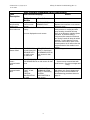
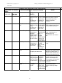
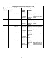
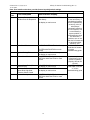
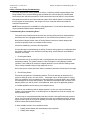
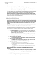
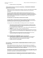
Software Revs 3,5,6,8, 10, 12
10/12/2006
Infinity /Evolution Troubleshooting (Rev. 2)
Infinity/ Evolution Troubleshooting Guide
User Interface Software Ver. -03, -05, -06, -08, -10 and -12
Table of Contents
User Interface Software Identification…………………………..2
Critical Malfunction Description……………………………….....2
System Malfunction Description……………………………….…3-4
Troubleshooting
Equipment Status, Checkout, Service Menus………………...5
Communication and Installation Problems…………………….5
Intermittent Loss of Communication……………………………6
Non-Zone Under-Conditioning or Over-Conditioning….…..…6
Clean or Replace Filter Pop Up Message………………..……7
ERV/ HRV not Recognized by System…………………………7
User Interface Generated Fault Code Descriptions………..…8-10
Outdoor Unit Generated Fault Code Descriptions……....……11-12
Fan Coil Generated Fault Code Descriptions….……………...13
Furnace Generated Fault Code Descriptions…………….…...13-14
Airflow, Static Pressure and RPM readings…………...…….…9
Zoning troubleshooting………………………..……………....…16-19
.
Damper Troubleshooting and Replacement…………………...19
Before condemning User Interface or Circuit Board……...…..20
Troubleshooting Communication Bus…………………...……..21
Communication Bus Voltage Check………………….…..…….22
Software Revs 3,5,6,8,10, 12
10-12-2006
Infinity /Evolution Troubleshooting (Rev. 2)
User Interface Software Identification
This guide covers Infinity and Evolution zoning and non-zoning systems with versions CESR131339-03, 05, -06, -08, -10, and -12 software (versions 7, 9, and 11 were not put into production) . The model
numbers included are listed below:
Carrier: SYSTXCCUIZ01, SYSTXCCUIZ01-A, SYSTXCCUID01, SYSTXCCUID01-A
Bryant: SYSTXBBUIZ01, SYSTXBBUIZ01-A , SYSTXBBUID01, SYSTXBBUID01-A
There are two ways to determine the software version: enter the Service menus with a 10 second push of
the Advance button, or cycle power to the User Interface. When power is re-applied, the User Interface
will re-establish communications with the equipment and display the software version as shown below:
ESTABLISHING
COMMUNICATIONS
WITH EQUIPMENT
PLEASE WAIT
WORKING
SOFTWARE VERSION
CESR131339-06
The first Service menu screen will show the software version near the bottom of the screen. Infinity and
Evolution systems are designed to alert the equipment owner of a potential system problem, and help
guide the servicer in determining a system problem. Two types of alerts can pop up on the User Interface
screen when a system problem or potential system problem exists. These alerts are described below.
Critical Malfunctions (software versions 3,5,6,8 only)
Certain system problems will result in the message “CRITICAL MALFUNCTION CALL TECHNICIAN”.
A critical malfunction is a system problem that will result in no system operation, and must be
addressed immediately. It usually means there is a problem related to the indoor unit blower motor.
The message will be displayed as shown in the figure below. The following will cause this message:
Fan Coil generated Critical Malfunctions:
OUTSIDE: 94o
Code 44 – Motor Communication Fault
Code 41 – Blower Motor Fault
FAN: AUTO
ALERT !
Furnace generated Critical Malfunctions:
CRITICAL MALFUNCTION
CALL TECHNICIAN
JOE'S HVAC SERVICE
(317) 555-1234
Code 15 – Blower Motor Lockout
Code 41 – Blower Motor Fault
2
The mode LEDs will
alternately flash red
on/blue off for 0.5 seconds,
then blue on/red off for 0.5
seconds.
Software Revs 3,5,6,8,10, 12
10-12-2006
Infinity /Evolution Troubleshooting (Rev. 2)
User Interface generated Critical Malfunctions:
No communication with indoor unit
System Malfunction
Certain system events can result in the pop-up message “SYSTEM MALFUNCTION CALL TECHNICIAN”.
A system malfunction is an event that could be related to a failed component, or an event that may not
necessarily indicate an equipment problem. If this message clears on its own and the equipment operates
normally, it should be ignored. If it does not clear, or comes back repeatedly after being dismissed, the
system should be checked at the owner’s earliest convenience.
The user can press the right side button to dismiss the notice. The regular run mode screen will then
appear except “SYSTEM MALFUNCTION” will appear in place of the day/time. If the error has not
disappeared within 24 hours, the above display will return.
If the error code disappears, “SYSTEM MALFUNCTION” will disappear and the day/time will reappear.
OUTSIDE: 94o
FAN: AUTO
JOE'S HVAC SERVICE
(317) 555-1234
SYSTEM MALFUNCTION
CALL TECHNICIAN
DISMISS
NOTICE >
This message may be generated from any of the communicating system components, and will be
displayed as shown in Figure 2. The following events may generate this message:
Fan Coil generated System Malfunction events:
Code 37 – Heater output sensed On when not energized (User interface will only display the pop-up
message, modifications to fan/staging operation will not occur)
Code 44 – Motor Communication Fault (version 10)
Code 41 – Blower Motor Fault (version 10)
Furnace generated System Malfunction events:
Code 13 – Limit Circuit Lockout
Code 14 – Ignition Lockout
Code 21 - Gas Heating Lockout
Code 22 - Abnormal Flame Proving Signal
Code 23 – Pressure Switch Did Not Open
Code 24 – Secondary Voltage Fuse Open
Code 33 – Limit Circuit Fault AND high heat only is active
Code 45 – Control Circuitry Lockout
Code 41 – Blower Motor Fault ((-A) models only)
2-Stage outdoor unit generated System Malfunction events (38TDB, YDB,
598B, 698B):
-VC VOLTAGE AT STANDBY (versions 8 and earlier)
-HI CAPACITY COMPRESSOR LOCKOUT (versions 8 and earlier)
3
Software Revs 3,5,6,8,10, 12
10-12-2006
Infinity /Evolution Troubleshooting (Rev. 2)
(-A) Models( Ver. 10 & 12 Software )Outdoor Unit System Malfunction Events
Outdoor board Flash Code Fault Description
(2006 Platform units)
User Interface Display in Service Screen
45
47
73
74
76
78
79
81
82
83
84
85
86
87
Control Fault
No 230v
Contactor shorted
No high voltage
Low speed didn’t start 3 times
High speed didn’t start 3 times
Run Capacitor Failed
Low capacity thermal lockout
Hi capacity thermal lockout
Low Capacity Compressor Lockout
Hi Capacity Compressor Lockout
Low Contactor Open
Low Contactor Shorted
High Contactor Open
CONTROL FAULT
NO 230V AT UNIT
CONTACTOR SHORTED
NO 230V AT COMPRESSOR
LOW STAGE REPEAT NO START
HIGH STAGE REPEAT NO START
RUN CAPACITOR FAILED
THERMAL LOCKOUT IN LOW STAGE 4 HOURS
THERMAL LOCKOUT IN HIGH STAGE 4 HOURS
LOW PRESSURE LOCKOUT 4 HOURS
HIGH PRESSURE LOCKOUT 4 HOURS
LOW CONTACTOR OPEN
LOW CONTACTOR SHORTED
HIGH CONTACTOR OPEN
88
High Contactor Shorted
HIGH CONTACTOR SHORTED
89
Start Capacitor/Relay Failed
START CAPACITOR/RELAY FAILED
Zone board generated System Malfunction events:
-Fuse Open
User Interface generated System Malfunction events:
-Indoor unit communication fault
-Outdoor unit communication fault
-NIM communication fault
- Zone board communication fault
-Defrost Locked
-SAM communication fault
-Frozen indoor coil detected (version 10)
SAM generated System Malfunction events
-Code 45-EEPROM memory error
-Code 62-Loss of communication with the radio: No communication with device for 2 minutes(Version 10
only)
4
Software Revs 3,5,6,8,10, 12
10-12-2006
Infinity /Evolution Troubleshooting (Rev. 2)
Troubleshooting
The Infinity and Evolution Systems are designed to record and store system faults and events that may
be used to help lead a servicer to the root cause of a real or perceived system problem. It should be
understood that not all recorded events necessarily represent system problems. These should be used
as a clue to guide the servicer to the appropriate part of the system.
Equipment Status
To check equipment status, push and hold the right side button for 3 seconds. This will show what the
User Interface is telling the system to do. Compare this information to what is actually happening. This
can help lead you to a component problem.
Checkout
This system gives you the ability to exercise all the system components and accessories to verify proper
operation. Access this by pressing the Advanced button for 10 seconds.Select CHECKOUT, then select
the component you wish to exercise and follow screen prompts.
NOTE: Airflow during in Checkout mode is defaulted to Efficiency regardless of AC Airflow
setting
Service Menus
The Service Menus provide system information to aid in troubleshooting. To access, press and hold the
Advanced button for 10 seconds and select “Service”. This will allow you to check status of individual
system components, view the Last 10 System Faults, the Run/Fault History and more.
Checking system status should be one of the first steps in troubleshooting these systems.
Troubleshooting Communication and Installation Problems
This system uses digital communication on a communication bus (A and B wires) to send commands to
operate equipment and send error messages to the User Interface to display. At initial installation, the
system first finds all “communicating” equipment on the bus, and self configures to the appropriate
equipment attached. If a piece of equipment is non- communicating such as an older outdoor unit or
accessory, the size or type will need to be input by the installer during the learning process.
Each communicating device contains a green communication light to verify if communication has been
established. This is a clue to where a potential problem lies.
Component not found at initial installation: first attempt to reinstall by entering the service screens
and selecting INSTALL. Try this several times before proceeding with troubleshooting
A communication error exists, or equipment cannot be found by the User Interface: This may be
due to a wiring problem with any of the components or accessories of the system. For example, a short
in the wiring to the outdoor unit or accessory, may block communication with the indoor unit. In the
majority of instances, using the step by step method described on page 21 will isolate the problem to the
appropriate piece of equipment. If during Start up: CANNOT COMMUNICATE WITH EQUIPMENT is
displayed on a furnace installation, make sure all dipswitches on SW-4 are turned off.
If a problem is isolated to the outdoor unit (comm error only occurs when outdoor unit is connected to the
bus), the problem may be in the thermostat wire, or the outdoor unit wiring. If thermostat wire checks out
OK, check wiring inside the unit control box. Make sure all wires are tightly attached, and run to the
Mis-wiring in outdoor unit will cause loss of communication
and operational problems in this system.
appropriate terminal.
5
Software Revs 3,5,6,8,10, 12
10-12-2006
Infinity /Evolution Troubleshooting (Rev. 2)
Intermittent loss of communication
If communication errors occur at random intervals, and no system problems can be
found by using the troubleshooting method described above, there may be a problem
with outside electrical noise that affects system communication. First, trace all wires
and ensure they are not in close proximity to high voltage, or other electrical equipment
wiring such as alarm systems, fluorescent lighting, or recording equipment. Ensure
there is sufficient separation between these wires, and a good common connection all
the way through.
If this does not correct the situation, properly installing shielded thermostat wire may be
required to stop external interference from affecting system communications.
Situation: Non-Zoned system over-conditioning or under-conditioning
Options:
•
•
•
Evaluate User Interface location. Make sure nothing is influencing
temperature reading such as heat from direct sunlight. Make sure hole in
wall behind User Interface is plugged.
If the system is over-conditioning, increase the anticipator setting. This
adjustment is located in the Thermostat Setup, Cycles per Hour screen
If the system is under-conditioning, lower the anticipator setting and if
necessary, increase the cycles per hour. This adjustment is located in the
Thermostat Setup, Cycles per Hour screen
6
Software Revs 3,5,6,8,10, 12
10-12-2006
Infinity /Evolution Troubleshooting (Rev. 2)
Situation: Clean or Replace Filter is displayed after a short period of time
These systems have a feature called TrueSense filter detection. This feature reads the change in
static pressure caused by the filter accumulating dirt. At 1:00 pm each day the system will take a
reading and record the change in static pressure. The clean or replace filter message will pop up
when the filter is full.
This feature operates by setting a base line static pressure based on the highest airflow the system
could run (this could be heat or cool airflow). The measurement is taken at a low airflow, and then
calculated up to the highest airflow the system could see. An enhancement to the (-A) model was
that if a furnace is used and it is locked in low fire, the calculation will use the higher of the cooling
airflow or low furnace heat airflow. In previous versions, it used the higher of high furnace airflow or
cooling airflow even if the furnace was locked in low fire.
In (-A) models (version 10 and 12 software), clean filter routine was changed to eliminate nuisance
pop up messages when a marginal duct system is used. When the initial static pressure is 0.7
inches or higher, a modified calculation is used to allow this feature to be used at higher static
pressures. With –A models, it will only pop up immediately if the initial static is 1.5 inches or higher.
This truly indicates a ductwork problem that must be addressed.
Options if this pops up quickly:
•
•
•
Evaluate duct work and make improvements to lower static pressure where possible
Change filter type to EAC. This will display the message based on time instead of static
pressure change
Turn the filter reminder to off in the homeowner’s Advance Setup
Situation: ERV/ HRV Not Recognized By System
A ventilator may be connected to the system by wiring directly to a Damper Control Module (DCM) in a
zoned system, or an Network Interface Module (NIM) in a non-zoned system. The system recognizes a
ventilator is connected when the ventilator is wired to the YEL, RED, GRN, and BLU terminals of the NIM
or DCM, and the ventilator is powered.
If the ventilator is not found, check for 12 volts DC between Y (+12 vdc) and B (ground) terminals of the
ventilator. If voltage is not detected, the ventilator will not be found by the system. Make sure ventilator is
powered.
7
Software Revs 3,5,6,8,10, 12
10-12-2006
Infinity /Evolution Troubleshooting (Rev. 2)
User Interface Generated Fault Descriptions
Fault
Description
User Interface Display
Original
Models
Onboard
temp/humidity
sensor error
Blower cutback
from indoor unit
Action
-A models
NO SENSOR
TEMP/HUMIDITY
DATA on main
SENSOR FAULT
screen
EXCESS STATIC PRESSURE in fault
history
No error displayed on main screen
Remote Room
Sensor failed
ZONE SENSOR
in fault history NO
SENSOR DATA
on main screen
for that zone
REMOTE SENSOR
FAULT in fault history
NO SENSOR DATA on
main screen for that
zone
Smart sensor
zone x
communication
fault
SMART SENS ZONEx COMM in fault history
NO SENSOR DATA on main screen for that
zone
Indoor unit
communication
fault
IDU COMM
FAULT in fault
history
CRITICAL
MALFUNCTION
on main
INDOOR UNIT
COMMUNICATION
FAULT in fault history
SYSTEM
MALFUNCTION on
main screen
8
Sensor on User Interface has failed.
Replace User Interface or use remote
sensor for zone 1
Max RPM was reached due to high
static pressure. In cooling and heat
pump heating, the airflow will step
down in an attempt to maintain system
operation. In furnace heating, if
minimum airflow cannot be achieved,
the Zoning Control will dump air where
possible or shut down the furnace
until more zones call for heat. In nonzoned systems, the UI will not shut the
equipment down. See details in next
section.
Check wiring and ohm out sensor.
System cannot communicate with
smart sensor. Check bus voltages and
wiring.
User interface has lost communication
with indoor unit. Check voltages and
wiring. Perform communication bus
troubleshooting procedure shown on
page 21.
Software Revs 3,5,6,8,10, 12
10-12-2006
Infinity /Evolution Troubleshooting (Rev. 2)
User Interface Generated Fault Descriptions cntd.
Fault
Description
User Interface Display
Original
Models
Outdoor unit
communication fault
Action
-A models
Zone board 1
communication fault
ODU COMM
OUTDOOR UNIT
FAULT in fault
COMMUNICATION FAULT
history
fault history
SYSTEM
MALFUNCTION
SYSTEM MALFUNCTION
on main screen
on main screen
ZONE 1-4 COMM FAULT in fault history
SYSTEM MALFUNCTION on main screen
Zone board 2
communication fault
ZONE 5-8 COMM FAULT in fault history
SYSTEM MALFUNCTION on main screen
NIM communication
fault
Defrost error
NIM COMM FAULT in fault history
SYSTEM MALFUNCTION on main screen
DEFROST LOCKED in fault history
SYSTEM MALFUNCTION on main screen
Stage down due to
noise control
AIRFLOW
LIMITED. STAGE
DOWN
OCCURRED in
fault history
AIRFLOW LIMITED.
SHUTDOWN OCCURRED
In fault history
No display on main screen
No display on
main screen
User interface has lost communication
with outdoor unit. Check wiring between
user interface and outdoor unit. Check
bus voltages on user interface and
outdoor unit. Also check for low voltage
short in outdoor unit control wiring.
User interface cannot communicate with
damper control module. Check bus
voltages and wiring.
User interface cannot communicate with
damper control module. Check bus
voltages and wiring.
User interface cannot communicate with
NIM. Check bus voltages and wiring.
The outdoor unit has been in defrost for
15 minutes.
A zone has reached its airflow limit setting
and the system has compensated by
staging down or shutting down. The
system is designed to do this to control air
noise, and this does not necessarily
reflect a problem with the system. See
detailed description in Zoning
Troubleshooting section.
Zone Board Fuse
blown
Zone X Sensor
24 - ZONE BOARD FUSE in fault history
SYSTEM MALFUNCTION on main screen
55 - ZONE SENSOR in fault history
NO SENSOR DATA on main screen for that
zone
Change fuse
LAT/HPT Sensor
LAT/HPT SENSOR in fault history
No display on main screen.
Check sensor. These sensors are
optional and are for display purposes
only. The system does not react to LAT or
HPT temperature inputs.
9
Check zone sensor
Software Revs 3,5,6,8,10, 12
10-12-2006
Infinity /Evolution Troubleshooting (Rev. 2)
User Interface Generated Fault Descriptions cntd.
Fault Description
User Interface Display
Original
-A models
Models
Action
SAM radio test failed
Not applicable to
original models
SAM RADIO
TEST FAILED
SAM profile failed
Not applicable to
original models
Not applicable to
original models
SAM PROFILE
FAILED
POSSIBLE
FROZEN COIL in
fault history.
SYSTEM
MALFUNCTION
on main screen
Radio not able to access Skytel satellite. Ensure
full coverage is available by checking Skytel web
site. If available, try another location closer to
outside wall.
SAM not able to communicate equipment profile
to Skytel satellite
Static pressure change related to frozen coil
detected. Unit will shut down outdoor unit and run
indoor fan at low speed for 1 hour. Cooling will
then resume if call exsists
Not applicable to
original models
UTILITY
CURTAILMENT
EVENT in fault
history
Frozen coil detected
Utility Curtailment
CURTAILMENT
ACTIVE on main
screen
16 (Zone Board status
light)
User Interface not
communicating with
Zone board
No display in fault history or on main
screen
10
Utility relay in outdoor unit has opened from utility
signal.
Or Utility Saver option has been enabled in the
Setup menu, but utility relay has not been
installed or is wired incorrectly.
Check for proper Utility Relay wiring, if no relay is
installed, enter Setup menu and disable Utility
Saver option.
Zone board not communicating with UI. Possibly
added after initial power up. Re-install the system,
check wiring between user interface and zone
board. Need sensor connected to at least 2
zones.
Software Revs 3,5,6,8,10, 12
10-12-2006
Infinity /Evolution Troubleshooting (Rev. 2)
Outdoor Unit Generated Fault Descriptions
Flash Code on Outdoor
Board
Fault Description User Interface Display
38TDB, YDB 24ANA, 25HNA
598B, 698B
187A, 180A,
286A, 288A
51
32
Low Pressure Switch
trip
Original
Models
-A models
LOW PRESS
SWITCH in fault
history
No display on
main screen
LOW PRESS
SWITCH OPEN
in fault history
No display on
main screen
Action
Switch is monitored at all times.
These may show up due to
low-pressure trips in low
outdoor temperature
conditions.
52
31
High Pressure Switch HIGH PRESS
trip
SWITCH in fault
history
No display on
main screen
HIGH PRESS High-pressure switch trip.
SWITCH OPEN Check refrigerant charge and
in fault history coils for airflow restrictions.
not display on
main screen
3
53
Outside Temp Sensor OAT SENSOR
in fault history
SENSOR
ERROR shown
in place of the
OAT value on
the main screen
Ohm out sensor and check
wiring. Could also be an
indication of los of
communication with outdoor
unit.
4
55
Coil Temp Sensor
Ohm out sensor and check
wiring
34
56
Thermistor Range
Error
6
73
NA
85
OUTDOOR AIR
TEMP SENSOR
FAULT in
history
SENSOR
ERROR shown
in place of the
OAT value on
the main scree
COIL SENSOR COIL TEMP
in fault history SENSOR
No display on
FAULT in fault
main screen
history.
No display on
main screen
RANGE ERROR in fault history
Improper relationship between
coil sensor and outdoor sensor.
No display on main screen
Make sure outdoor sensor is
located outside cabinet. Ohm
out sensors and check wiring.
Contactor Shorted
VC STANDBY CONTACTOR Voltage sensed at run capacitor
VOLTS in fault SHORTED in
when no call for compressor
history SYSTEM fault history
operation. Could be due to
MALFUNCTION SYSTEM
stuck contactor, of if contactor
on main screen MALFUNCTION is manually pushed in by
on main screen technician
Low Stage Contactor Not applicable LOW
Compressor voltage not
Open
to original
CONTACTOR detected when call for
models
OPEN in fault
operation and high voltage
history SYSTEM exits
MALFUNCTION
on main screen
11
Software Revs 3,5,6,8,10, 12
10-12-2006
Infinity /Evolution Troubleshooting (Rev. 2)
Outdoor Unit Generated Fault Descriptions Cntd.
Flash Code on Outdoor
Board
Fault Description User Interface Display
38TDB, YDB 24ANA, 25HNA
598B, 698B 187A, 180A,
286A, 288A
6
71
Low Capacity
Thermal Cutout
Original
Models
-A models
LO THERMAL
CUTOUT in
fault history
THERMAL
CUTOUT IN
LOW STAGE in
fault history
No display on
main screen
6
72
High Capacity
Thermal Cutout
HI THERMAL
CUTOUT in
fault history
No display on
main screen
6
6
6
47
81
82
No high voltage to
outdoor unit
VC STARTUP
VOLTS in fault
history
No display on
main screen
Low Capacity thermal LO COMP
Lockout
CUTOUT in
fault history
Hi Capacity thermal
Lockout
No display on
main screen for
older platform
outdoor unit
HI COMP
CUTOUT in
fault history
No display on
main screen
THERMAL
CUTOUT IN
HIGH STAGE in
fault history
No display on
main screen
NO 230V AT
COMPRESSOR
in fault history
SYSTEM
MALFUNCTION
on main screen
Voltage present on run
capacitor in lo speed then
disappears. Possible causes
are internal compressor
overload trip or start relay not
releasing.
Voltage present on run
capacitor in hi speed then
disappears. Possible causes
are internal compressor
overload trip or start relay not
releasing.
Voltage not present on run
capacitor when compressor
should be starting. Possible
causes: disconnect removed or
high voltage not connected.
THERMAL
Control detectes thermal cutout
LOCKOUT IN
in 3 consicutive low stage. On
LOW STAGE 4 cyles
HOURS in fault
history
SYSTEM
MALFUNCTION
on main screen
HERMAL
LOCKOUT IN
HIGH STAGE 4
HOURS in fault
history
SYSTEM
MALFUNCTION
on main screen SYSTEM
MALFUNCTION
on main screen
12
Action
Thermal cutout occurs in three
consecutive high cycles in new
platform outdoor units. On older
platform 2-stage units, or a
combination of 3 hi and low
cycles will cause this event.
Software Revs 3,5,6,8,10, 12
10-12-2006
Infinity /Evolution Troubleshooting (Rev. 2)
Fan Coil Generated Fault Descriptions
Flash
Code
16
Fault Description
User Interface Display
COM_FAULT in fault history
No display on main screen (16 code on fan
coil board)
25 Invalid Model/Motor Selection INVALID MODEL on main screen during
installation
26 Invalid Heater Size
INVALID HTR SIZE on main screen during
installation
27 Invalid Outdoor Unit Size
INVALID ODU SIZE on main screen during
installation
36 Heater output not sensed
HTR NOT SENSED in fault history
when energized
No display on main screen
37 Heater output sensed On
HTR STUCK ON in fault history
when not energized
SYSTEM MALFUNCTION on main screen
41 Blower Motor Fault
BLOWER FAULT in fault history
CRITICAL MALFUNCTION on main screen
44 Motor Communication Fault
BLWR COM FAULT in fault history
CRITICAL MALFUNCTION on main screen
46 Brown Out Condition
BROWN OUT
Note: User Interface selections override furnace board dipswitch settings
Action
System Communication Fault
See Fan coil
Installation
Instructions for error
descriptions.
Furnace Generated Fault Descriptions
Code
Fault Description
User Interface Display
12
Blower On After Power Up
BLOWER ON AFTER POWER UP in fault
history
No display on main screen
13
Limit Circuit Lockout
(Auto reset in 3 hours)
LIMIT CIRCUIT LOCKOUT in fault history
SYSTEM MALFUNCTION on main screen
14
Limit Circuit Lockout
(Auto reset in 3 hours)
Limit Circuit Lockout
IGNITION LOCKOUT in fault history
SYSTEM MALFUNCTION on main screen
BLOWER MOTOR LOCKOUT in fault
history
CRITICAL MALFUNCTION on main
screen
GAS HEAT LOCKOUT in fault history
SYSTEM MALFUNCTION on main screen
FLAME SENSE ERROR in fault history
SYSTEM MALFUNCTION on main screen
LPS OR HPS CLOSED in fault history
SYSTEM MALFUNCTION on main screen
24VAC FUSE OPEN in fault history
SYSTEM MALFUNCTION on main screen
MODEL/SETUP ERROR in fault history.
No display on main screen.
15
(Auto reset in 3 hours)
21
22
23
24
25
31
Gas Heating Lockout
(Control will not auto reset)
Abnormal Flame-Proving
Signal
Pressure Switch Did Not
Open
Secondary Voltage Fuse
Open
Model Selection Or Setup
Error
High-Heat Pressure Switch
Or Relay Did Not Close Or
Reopened
HPS OR RELAY OPEN in fault history.
No display on main screen
13
Action
Occurs when call for heat
satisfies during blower on
delay.
See Service / Status
Code label in furnace or
Furnace troubleshooting
guide
May see this fault during
quick power interruptions
See Service / Status
Code label in furnace or
furnace troubleshooting
guide
Software Revs 3,5,6,8,10, 12
Infinity /Evolution Troubleshooting (Rev. 2)
10-12-2006
Note: User Interface selections override furnace board dipswitch settings
Furnace Generated Fault Descriptions cntd.
Flash
Code
32
Fault Description
User Interface Display
Low-Heat Pressure Switch
Did Not Close Or Reopened
LOW PRESSURE SWITCH OPEN in
fault history
No display on main screen
33
Limit Circuit Fault
34
Ignition Proving Failure
41
Blower Motor Fault
42
Inducer Motor Fault (VS
Inducers Only)
Low-Heat Pressure Switch
Open While High-Heat
Pressure Switch Closed
Control Circuitry Lockout
43
45
LIMIT CIRCUIT FAULT in fault history
SYSTEM MALFUNCTION on main
screen
IGNITION FAULT in fault history
No display on main screen
BLOWER FAULT in fault history
CRITICAL MALFUNCTION on main
screen
INDUCER FAULT in fault history
No display on main screen
LPS OPEN HPS CLOSED in fault history
No display on main screen
CONTROL LOCKOUT in fault history
CRITICAL MALFUNCTION on main
screen
14
Action
This fault may show up
in the fault history of
condensing furnaces
due to unprimed trap
at start up, wind, or
other factors
temporarily affecting
the vent system. It is
not necessarily a
system problem. If
troubleshooting does
not determine a
problem, turn on low
heat rise in furnace set
up to boost inducer
airflow by 15%.
See Service / Status
Code label in furnace
or furnace
troubleshooting guide
41 codes may show up
in fault history, but if
system is operating
properly, this can be
ignored.
See Service / Status
Code label in furnace
or furnace
troubleshooting guide
Software Revs 3,5,6,8,10, 12
Infinity /Evolution Troubleshooting (Rev. 2)
10-12-2006
Checking Airflow, Static Pressure and RPM in the Service Menu
•
•
•
•
The airflow displayed in the Service screen is requested airflow, not actual airflow.
The static pressure displayed in the Service Screen is calculated based on requested
airflow, RPM and known system characteristics.
The RPM displayed in the Service screen is actual RPM.
Accuracy of static pressure readings is limited on some furnaces when RPM reaches
1100
RPM data can be used as an indicator of restrictive ductwork. When RPM maxes out, the Blower
Cutback flag is communicated to the furnace or fan coil control. This begins the Blower Cutback
algorithm which protects the motor from running at extreme conditions. The cutback algorithm is
explained in this document in the description of the EXCESS STATIC PRESSURE system
event.
Most furnaces and fan coils will deliver the requested airflow up to the maximum RPM. When a
system is not able to deliver the requested CFM at high static pressures, the accuracy of the
static pressure calculation is limited. See airflow information in Product Data to determine airflow
performance.
15
Software Revs 3,5,6,8,10, 12
10-12-2006
Infinity / Evolution Zoning Troubleshooting
Infinity /Evolution Troubleshooting (Rev. 2)
The Infinity and Evolution Zoning systems are unique, in that they prohibit a bypass damper from
being installed. This is a new technology that is possible due to the fact that only variable speed
blower motors are used in these systems. These motors allow control of airflow in every situation.
Most problems that will be encountered with this system will be airflow related. It is imperative that
the duct system be sized properly, and thought out in such a way that will accommodate the
customer’s requirements.
NOTE: Some structures are not suitable for zoning applications. Do not assume that this system
can be installed to FIX a ductwork related problem.
Troubleshooting Over Conditioning Zones
First check sensor locations and ensure they are not being influenced by air drafts behind the
wall. Make sure hole is plugged behind sensor or User Interface if the problem is in zone 1.
Next perform Damper/ Sensor check in Zoning Checkout screens to ensure dampers and
sensors are properly wired, to the damper control module.
If these are satisfactory, proceed to the steps below.
An important step in troubleshooting the Infinity / Evolution zoning system is to understand what
the system is being told to do, and what it is actually doing. Several features are available to
assist you in this task:
1. Check system status
Don’t assume a zone is not calling for heat or cooling because the set point matches the actual
temperature reading. The system controls in 16ths of a degree, but only displays in whole
numbers. There could be as much as 0.9 degree demand in a zone when the readings match.
This is enough demand to bring on high stage heat or cool.
Go into the service screens and check indoor unit status to determine current heat or cool stage.
2. Check Zoning Status
Proceed to zoning status to view damper positions. This is the best way to determine if the
system is calling for heat or cool into a zone. If a damper is open, and the system is running,
there is a probably a call for conditioning in that zone(unless it is opened slightly due to airflow
limit management or excess static pressure– see airflow limit description later in manual). If the
damper position is 0, and the zone is overconditioned, there may be an application problem.
3. Possible application issues causing over conditioned zone
If a zone is over conditioning and the damper position is 0, then you may have a damper
problem such as leakage issue, or conditioning from an andjacent zone may be carrying over
into the problem zone.
4. A zone may be overconditioned within limits due to Airflow Limit and Excess static pressure
issues. If a zone is set back more than 3 degrees from the most conditioned set point, and the
system needs to dump air to continue operating, that zone may be used as a dump zone. See
Airflow Limit and Excess Static Pressure
5. Other possible causes of over-conditioned zones
•
•
Partially broken damper wire intermittently losing connection.
Partially stuck damper
16
Software Revs 3,5,6,8,10, 12
10-12-2006
Infinity /Evolution Troubleshooting (Rev. 2)
Options to control over zone conditioning:
• Set airflow limits in small zones to MAX if air noise is acceptable
• Set points should be set no more than 3 degrees different from zone to zone
• Evaluate duct system and upsize or add supplies and returns where required
• Evaluate structure design for zoning suitability
The system will allow some over conditioning to ensure minimum airflow through the equipment
and maintain selected airflow limits. The system may not be capable of wide set point
differences. For example, if a customer wants the upstairs bedroom at 62 degrees in heating
and the downstairs zone at 70, the upstairs zone may be allowed to over condition (up to 67
deg) in order to satisfy minimum airflow requirements through the equipment, and /or selected
airflow limits. Below is a description of this process.
Airflow limits and equipment protection
The maximum airflow allowed into a zone is based on the relative size of the zone determined
by the duct assessment, and the airflow limits selected for each zone. Airflow limits are set to
high as factory default. This means that 200% of the assessed air flow is allowed into the zone.
Example if a zone size is determined to be 25% of the entire system, and the maximum airflow
(heating or cooling) is 2000 cfm, the maximum airflow into this zone is 2000 x 25% x 200% =
1000cfm.
This airflow limit multiplier can be adjusted to reduce or increase allowable noise levels; Low =
100%, Med = 150%, Max = 210% (will not cause stage down when reached).
If the system determines that it cannot deliver the airflow into a zone that needs conditioning,
and that zone has an airflow limit selected, the system will take the following 4 steps:
1. Reduce airflow if possible
a. 275 CFM per ton minimum in high stage cooling (325 if Dehum airflow set to
High). 175 CFM per ton in low stage cooling for Bristol units. Minimum airflow for
Copeland 2-stage outdoor units will vary.
b. Comfort Heat airflow is minimum for heat pump heating (3.5 x outdoor temp +
137) cfm /ton
c. Use heat pump comfort airflow as minimum if AC Airflow is Efficiency or MAX
c. No adjustment for furnace heating
2. Dump air to zones set to Unoccupied
a. Unoccupied zones can be conditioned up to the most conditioned set point
3. Dump air to zones with lower set points
a. Zones with lower set points may be conditioned to within 3 deg of the most
conditioned set point.
b. Increase or decrease all zones an additional 0.75 deg
4. Stage down equipment
a. Equipment will stage down or shut off if necessary
b. Fault history will record an event of (AIRFLOW LIMITED SHUTDOWN
OCCURRED)
c. If shut down occurs, other zones need to call before equipment will resume
operation
Options if Airflow Limits are not satisfactory and AIRFLOW LIMITED events are
occurring:
• Increase airflow setting to MAX in suspect zones if air noise is acceptable. The system
will not stage down when the airflow limit is set to MAX. In extreme cases, even a zone
set to MAX may cause a shut down on static pressure if the minimum airflow through
the equipment cannot be maintained. “EXCESS STATIC PRESSURE” will be recorded
in these cases.
• Evaluate duct design and make improvements where necessary
17
Software Revs 3,5,6,8,10, 12
10-12-2006
• Evaluate structure for zoning suitability
Infinity /Evolution Troubleshooting (Rev. 2)
Zoning system will not run or shuts down intermittently. “EXCESS STATIC PRESSURE”
appears in the last 10 faults
System may be held off until more zones are calling. If the zone or zones calling are not capable
of delivering the minimum required airflow, the system will wait until more zones call for
conditioning.
This system contains a Blower Cutback algorithm that will not allow the system to run in
extremely restrictive conditions. Blower Cutback is initiated when the blower has reached its
maximum RPM, and is unable to deliver the requested airflow. The blower sends a signal at the
maximum RPM which varies depending on the equipment installed. This usually occurs at
around 1200-1300 RPM.
The steps below occur when Blower Cutback has been initiated:
In furnace heating, or heat pump comfort heating, the system will stage down or shut down
immediately until more zones call for heat. In heat pump Efficiency heating, the airflow will be
reduced heat pump Comfort levels and stage down if that is not possible
In cooling, there is more airflow flexibility. The following process occurs in cooling mode:
•
•
•
•
•
CFM request is reduced in 50 CFM increments (this reduction is visible in the status
screens) Static pressure display is not valid in this range and should be ignored since
the unit cannot deliver the requested airflow.
If blower RPM is still above cutback levels, continue reducing CFM request about once
a minute
Reduce CFM request down to minimum CFM described above
If CFM is at minimum, and cutback is still in effect, begin the same airflow relief process
used for Airflow Limits and record EXCESS STATIC PRESSURE fault in last 10 system
events
If minimum airflow cannot be achieved after this process, stage down to low and
continue until Cutback is no longer active, or shut off if necessary
Options if EXCESS STATIC PRESSURE is active in Last 10 Events:
• Decrease airflow limit setting to from MAX to something else. This will engage the
airflow management algorithm sooner and may allow the system to run longer.
• Evaluate duct design and make improvements where necessary
• Evaluate structure for zoning suitability
Zoning Situation: “AIRFLOW LIMITED, STAGEDOWN/SHUTDOWN OCCURRED” appears in
the Last 10 Faults:
Factory default airflow limit is High in each zone. This means that the zone is allowed to
deliver 200% of the maximum assessed airflow. For example, if the maximum heating airflow
is 2000 CFM and a zone’s relative size is 25%, the maximum airflow for that zone when set to
High is calculated to be 2000 CFM * 25% * 200% = 1000 CFM
If the airflow limit is set to MED, the max allowable airflow is 150%, if set to LOW; 100%. If set
to MAX, there is no airflow limit, but the system could still shut down in heating if the maximum
motor RPM is reached due to EXCESS STATIC PRESSURE.
If the equipment owner is not complaining about zones being under conditioned, then this
message should be ignored. It indicates that the airflow limit was exceeded for a zone and the
18
Software Revs 3,5,6,8,10, 12
Infinity /Evolution Troubleshooting (Rev. 2)
10-12-2006
system needed to stage down. If the homeowner is complaining, then the airflow limit for that
zone should be raised. However, the homeowner may now experience excessive noise for that
zone. It should be communicated to the equipment owner that there is a trade-off between
comfort and noise when these airflow limits are adjusted.
Zoning Situation: When increasing the set temperature for a zone, the heating does not
come on until the set temperature is 3 degrees over all of the other zones.
The system may not allow equipment to turn on after a set point adjustment if there are not
enough zones calling. Once a difference of 3 degrees exists between zones, the system can
then use those setback zones as dump zones, and the system may now turn on. Lowering the
set point back to within 3 degrees may cause the equipment to turn off. If the airflow limits are
set to Maximum, then this problem does not occur.
Zoning Situation: Continuous Fan used in some zones but not in others. Dampers are
opening in zones where fan is set to Auto
Each indoor unit must deliver a minimum airflow in continuous fan mode. If the system
determines that this airflow cannot be met due to duct capacity to zones requiring air, it will open
zones set to Auto in order to deliver the required air. This is designed into the system and is not
an equipment problem.
Damper output check
Carrier and Bryant residential zoning dampers are designed to move from full open to full close
or vice versa in 15 seconds. They are driven by 24vac triac inputs. When checking the zone
board for damper outputs, a voltmeter can be used to check between common –open or
common-closed while the damper is driving. Since the output is driven by triacs, some voltage
may be present when the dampers are not driving due to triac leakage. This voltage will is not
capable of driving a load.
When checking outputs on the damper control module, you may notice that voltage is present on
both open-common and closed-common when the damper should be moving. This is not a
problem with the damper control module. The circuitry in the actuator determines which direction
the actuator will move.
Replacing Damper actuators
The range of motion for rectangular dampers is different from round dampers. A rectangular
damper moves through 90 degrees and the round damper moves through 45 degrees. Both will
open or close fully in 15 seconds, thus the rectangular actuator rotates twice as fast as a round
actuator. Ensure the proper actuator is selected.
19
Software Revs 3,5,6,8,10, 12
10-12-2006
Before condemning the User Interface or circuit board
Infinity /Evolution Troubleshooting (Rev. 2)
Re-install the system:
In some situations, there may have been changes and additions to the system set up after initial
installation. This can cause problems because the system has not been “told” of the changes,
and it does not recognize them. Cycling power does not tell the system a new component
has been installed. Follow the steps below:
-Push and hold Advance for 10 seconds
-Install
Follow screen prompts
Reset Factory Defaults:
This will put you back to the beginning and could avoid confusion from unknown changes to the
system configuration. Follow steps below:
•Push and hold Advance for 10 seconds
•Setup
Thermostat
Reset Factory Default
Program Schedule-YES
User Settings- YES
Install Settings- YES
Last 10 Faults – YES
Changing components
If a circuit board is changed, remember that the fault history is maintained in the User Interface Last 10
System Events. Faults from the previous failed components will remain in the history unless cleared.
20
Software Revs 3,5,6,8,10, 12
10-12-2006
Infinity /Evolution Troubleshooting (Rev. 2)
Troubleshooting Communication Bus
CAN NOT FIND INDOOR UNIT
Disconnect O.D. unit
and all other devices
on ABCD bus except
indoor unit and UI.
Cycle system power.
Indoor
unit
found?
Reconnect one
device at a time to
ABCD bus.
YES
NO
Connect UI to indoor
unit at the indoor unit.
YES
Device
found?
NO
Indoor
unit
found?
YES
Check wiring to UI
mounting location.
Check device
wiring.
NO
YES
Wiring
OK?
Try
another
UI?
NO
NO
Correct
wiring and
reinstall
system.
Measure voltage on ABC
terminals at indoor unit (see
Table-1) Possible indoor unit
problem.
21
YES
Measure
voltage on
ABC
terminals at
device (see
Table- 1)
Possible
device
problem.
Software Revs 3,5,6,8,10, 12
10-12-2006
Infinity /Evolution Troubleshooting (Rev. 2)
TABLE 1
Advance Troubleshooting
Fan Coil / Furnace / 2-stage Communication Bus
FE Control Board
Furnace Control Board
Two-Speed Control Board
-Voltage Readings With board Power applied, and No U.I. connected, all other devices disconnected
A to B
A to C
B to C
C to D
~3 vdc
~3 vdc
~.01 to 0.3 vdc
24 vac
The above readings are meant to prove that the communication driver is not dead or shorted.
It does not guarantee that the unit will communicate. If communication problems exist and
voltage read good, an external short in the thermostat wiring, or a mis-applied accessory
may be the cause.
-Voltage Readings With board Power applied, and U.I. Applied, all other devices disconnected
A to B
A to C
B to C
C to D
~2.5 to 3.9 vdc (pulsating)
~2.5 to 3.9 vdc (pulsating)
~0.1 to 0.9 vdc (pulsating)
24 vac
The above readings are meant to prove the communication drivers are functioning, are not
open or shorted, and wiring between devices is OK. If voltages check out OK and
communication problems still exist, it could be a board problem.
22