1
Page 1
SET 4703
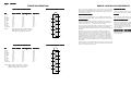
TUNER INFORMATION
MAIN TUNER TERMINAL GUIDE
2.2V
1.2V
1.2V
4.8V
4.8V
0V
5.0V
0V
33.5V
0V
0V
1.7V
6.0V
1.2V
4.8V
4.8V
0V
5.0V
0V
33.5V
0V
0V
NOTE:
VHF Low Band voltages taken on channel 2.
VHF High Band voltages taken on channel 7.
UHF Band voltages taken on channel 14
(2)
(4)
(6)
(10)
(3)
(5)
τ
(7)
τ
(9)
τ
(11)
1.8V
6.0V
1.2V
4.8V
4.8V
0V
5.0V
0V
33.3V
0V
0V
(2)
(4)
(6)
(8)
(10)
τ
(1)
τ
(3)
τ
(5)
τ
(7)
τ
(9)
τ
(11)
τ
2.3V
1.2V
1.2V
4.8V
4.8V
0V
5.0V
0V
33.3V
0V
0V
τ
(1) AGC
(2) TU
(3) EN/AS
(4) CLK
(5) DATA
(6) 9V
(7) 5V
(8) LOCK
(9) 33V
(10) IF2
(11) IF OUT
τ
UHF Band
τ
VHF Lo
w Band VHF High Band
Low
NOTE: VHF Low Band voltages taken on channel 2.
VHF High Band voltages taken on channel 7.
UHF Band voltages taken on channel 14
τ
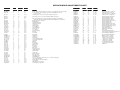
SUB TUNER TERMINAL GUIDE
Pin
2.1V
4.0V
1.2V
4.8V
4.8V
0V
5.0V
0V
33.3V
0V
0V
(1)
τ
(8)
SUB TUNER VOL
TAGE CHAR
T
OLT
CHART
τ
τ
2.0V
4.1V
1.2V
4.8V
4.8V
0V
5.0V
0V
33.5V
0V
0V
τ
(1) AGC
(2) TU
(3) EN/AS
(4) CLK
(5) DATA
(6) 9V
(7) 5V
(8) LOCK
(9) 33V
(10) IF2
(11) IF OUT
τ
UHF Band
τ
VHF Lo
w Band VHF High Band
Low
τ
Pin
τ
MAIN TUNER VOL
TAGE CHAR
T
OLT
CHART
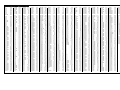
MISCELLANEOUS ADJUSTMENTS
This receiver employs digital customer controls which are accessed through
the service menu. All adjustments were performed at reset unless otherwise
indicated. Record all the data values for all functions in the service menu
before making any changes.
HORIZONT
AL SIZE
HORIZONTAL
HIGH VOL
TAGE CHECK
OLT
RF A
GC
AGC
Tune in a picture. Set brightness and color to minimum. Connect a high
voltage probe to CRT anode. High voltage should read from 27kV to 29kV.
Tune in a picture. Adjust R1202 to a point where snow appears in picture,
then to a point where snow disappears.
SER
VICE MENU
SERVICE
COLOR TEMPERA
TURE
TEMPERATURE
To access the service menu adjustments by using the remote transmitter
keypad, press and hold the menu button until the menu display disappears
from the screen. Key in 9, 8, 7, 6, and press the enter button.
Tune in a crosshatch pattern. Set brightness, picture, and color to minimum.
Call up service menu, select functions 27, 28, and 29, set data values to 0.
Adjust data values for functions 30, 31, and 32 of the two least predominate
colors to obtain a white pattern. Tune in an active black and white channel
and adjust functions 27, 28, and 29 for best white to black tracking at high
and low brightness.
To access the service menu adjustments by using the receiver keypad, press
the menu button until the display disappears from the screen. Without
releasing the menu button simultaneously press the adjust right and channel
up buttons.
The receiver is now in service menu mode with function 03 H Pos 16
displayed. The first line on the service menu is a version number of the
software used in the receiver. On the bottom is a date the module went
through the factory. Use the select up and down buttons to select function.
Use the adjust buttons to make changes to selected function. The function
00 F Mode (Factory Mode) is always set to 0. Only the first seven items in
the service menu can be brought up. Use the select key to select the 00 F
Mode function and change the adjustment to 1, now all the menu items will
be accessible.
NOTE: Set value of function 00 F Mode (Factory Mode) to 0 before exiting
the service menu mode. If not set to 0 the receiver will not shut off with the
remote or power button on the receiver.
Tune in a crosshatch pattern. Call up service menu, select function 11, set
data value for slight overscan on both sides.
COLOR PURITY / CONVERGENCE
CRT and yoke are bonded. Color purity and convergence adjustments are
not recommended.