1
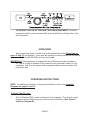
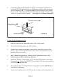
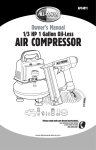
APC4017
TM
Owner’s Manual
20 Gallon Vertical
AIR COMPRESSOR
Please read and save these instructions.
HAVE QUESTIONS OR NEED SERVICE
DO NOT RETURN TO STORE!
888-896-6881
www.allpoweramerica.com
SPECIFICATIONS TABLE
Maximum Air Pressure
Air Tank Capacity
Air Flow Capacity
Motor
Required Circuit
Pump Stage
Air Outlet Size
Accessories
115 PSI
20 Gallons
6.2 CFM at 90 PSI
5.2 CFM at 40 PSI
2.5 HP Working / 4 HP Peak
120 Volt / 60 Hz / 12 A / 1-Phase
Minimum 20 Amp *Dedicated
Single
1/4” - 18 NPT
Air Intake Filter; Air Hose Coupler
#233060
*A dedicated circuit is used only for a single load, for this compressor. Other loads on the circuit must be
disconnected or turned off when the compressor is plugged in.
SAVE THIS MANUAL
You will need this manual for the safety warnings and precautions, assembly, operating, inspection, maintenance and cleaning procedures, parts list and assembly diagram.
Keep your invoice with this manual. Write the invoice number on the inside of the front
cover. Keep this manual and invoice in a safe and dry place for future reference.
GENERAL SAFETY WARNINGS AND PRECAUTIONS
1.
KEEP WORK AREA CLEAN AND DRY. Cluttered, damp, or wet work areas
invite injuries.
2.
KEEP CHILDREN AWAY FROM WORK AREA. Do not allow children to handle
this product.
3.
KEEP IDLE EQUIPMENT. When not in use, tools and equipment should be kept
in a dry location to inhibit rust. Always lock up tools and equipment, and keep out
of reach of children.
4.
DO NOT USE THIS PRODUCT IF UNDER THE INFLUENCE OF ALCOHOL OR
DRUGS. Read warning labels on prescriptions to determine if your judgement or
reflexes are impaired while taking drugs. If there is any doubt, do not attempt to
use this product.
5.
USE EYE AND HAND PROTECTION. Wear ANSI-approved safety impact
goggles and heavy-duty work gloves when using this product. ANSI-approved
safety impact eyeglasses and heavy-duty work gloves are available from Harbor
Freight Tools.
6.
DRESS SAFELY. Do not wear loose clothing or jewelry, as they can become
caught in moving parts. Wear a protective hair covering to prevent long hair from
becoming caught in moving parts. If wearing a long-sleeve shirt, roll sleeves up
above elbows.
PAGE 2
7.
DO NOT OVERREACH. Keep proper footing and balance at all times to prevent
tripping, falling, back injury, etcetera.
8.
INDUSTRIAL APPLICATIONS MUST FOLLOW OSHA REQUIREMENTS.
9.
STAY ALERT. Watch what you are doing at all times. Use common sense. Do
not use this product when you are tired or distracted from the job at hand.
10.
CHECK FOR DAMAGED PARTS. Before using this product, carefully check
that it will operate properly and perform its intended function. Check for dam aged parts and any other conditions that may affect the operation of this product.
Replace or repair damaged or worn parts immediately.
11.
REPLACEMENT PARTS AND ACCESSORIES: When servicing, use only identical replacement parts. Only use accessories intended for use with this product.
Approved accessories are available from Harbor Freight Tools.
12.
MAINTAIN THIS PRODUCT WITH CARE. Keep this product clean and dry for
better and safer performance.
13.
MAINTENANCE: For your safety, service and maintenance should be performed
regularly by a qualified technician please call Toll Free: 888-896-6881.
14.
USE THE RIGHT TOOL FOR THE JOB. Do not attempt to force a small tool or
attachment to do the work of a larger industrial tool. There are certain applications for which this tool was designed. It will do the job better and more safely
at the rate for which it was intended. Do not modify this tool, and do not use this
tool for a purpose for which it was not intended.
15.
WARNING: The warnings, precautions, and instructions discussed in this manual
cannot cover all possible conditions and situations that may occur. The operator
must understand that common sense and caution are factors, which cannot be
built into this product, but must be supplied by the operator.
PAGE 3
SPECIFIC PRODUCT WARNINGS AND PRECAUTIONS
1.
WARNING: Make sure to fill the Air Compressor with a premium quality,
30-weight, non-detergent compressor oil before each use. Running the Air Compressor with no oil or low oil will cause damage to the equipment. Note: The oil
reservoir has an optimal capacity of 30 ounces of oil.
2.
WHEN CHECKING THE OIL LEVEL: Make sure to unscrew (do not pull) the
Breather Valve (14B) out. (See Figure C, and Assy. Diagram B.)
3.
MAKE SURE ALL TOOLS AND EQUIPMENT USED WITH THE AIR COMPRESSOR ARE RATED TO THE APPROPRIATE CAPACITY. Do not use any
tool or equipment that does not operate from 0 to 115 PSI.
4.
DRAIN AIR COMPRESSOR EVERY DAY. Do not allow moisture to build up
inside the Air Compressor. (See “INSPECTION, MAINTENANCE, AND CLEANING” section of this manual.)
5.
MAINTAIN A SAFE WORKING ENVIRONMENT. Keep the work area well lit.
Make sure there is adequate surrounding workspace. Always keep the work
area free of obstructions, grease, oil, trash, and other debris. Do not use the Air
Compressor in areas near flammable chemicals, dusts, and vapors.
6.
AVOID INJURY: Never direct the Air Flow Valve (6A) at people or animals. (See
Assy. Diagram A.)
7.
DO NOT ALTER OR REMOVE THE FACTORY SEALED PRESSURE
RELEASE VALVE (5A). (See Assy. Diagram A.)
8.
DO NOT OPEN THE WATER DRAIN VALVE (10A) SO THAT MORE THAN
FOUR THREADS ARE SHOWING. (See Assy. Diagram A.)
9.
AN EXTENSION CORD MUST NEVER BE USED WITH THIS ITEM.
Connecting this item to an outlet through an extension cord MAY CAUSE
ELECTRICAL DAMAGE TO THE MOTOR and could present a FIRE HAZARD.
10.
THIS COMPRESSOR MAY REQUIRE A DEDICATED ELECTRICAL CIRCUIT
AS THE AMPERAGE DRAW UNDER FULL LOAD COMBINED WITH USE OF
ANY OTHER ITEM MAY OVERLOAD YOUR CIRCUIT.
11.
WARNING: This product contains or produces a chemical known to the State of
California to cause cancer and birth defects (or other reproductive harm).
(California Health & Safety Code § 25249.5, et seq.)
12.
WARNING: People with pacemakers should consult their physician(s) before
using this product. Operation of electrical equipment in close proximity to a heart
pacemaker could cause interference to or failure of the pacemaker.
PAGE 4
TO EXTEND THE LIFE OF YOUR AIR TOOLS AND EQUIPMENT, it is recommended to install an oiler and water filter in series with the Air Output Line of the
Air Compressor.
UNPACKING
When unpacking, check to make sure all the parts shown on the Parts Lists on
pages 9, and 10 are included. If any parts are missing or broken, please call our service
department Toll Free 888-896-6881 as soon as possible.
IMPORTANT! This compressor is shipped with the oil fill plug removed and without
oil. The oil fill plug is attached to the power cord as a reminder to add oil to the
crankcase. Add oil to the proper level as explained below and secure the oil fill
plug before use.
OPERATING INSTRUCTIONS
NOTE: For additional references to the parts listed below, refer to the Assembly
Diagrams on pages 9, and 10.
To Check The Oil Level:
1.
The Oil Window (20B) is used to determine if oil is needed. The oil level should
always be at the maximum level (red line on the Oil Window). (See Figure C,
and Assy. Diagram B.)
PAGE 5
2.
If necessary, add a premium quality, 30-weight, non-detergent compressor oil
into the Oil Fill Hole until the level of oil reaches the maximum level as indicated
on the Oil Window (20B). The optimal capacity of the oil reservoir is 30 ounces.
Do not overfill. Then thread the Breather Valve back into the Oil Fill Hole, being
careful not to strip the plastic threads.
(See Figure C, and Assy. Diagram B.)
Breather Valve (14B)
Front Cover (18B)
Oil Window (20B)
FIGURE C
To Turn The Air Compressor On:
1.
Check to make sure the Water Drain Valve (10A) is fully closed.
2.
Turn the Air Flow Valve (6A) to its “OFF” position.
3.
Connect the air hose (not provided) to the Air Flow Valve (6A) of the Air Compressor. Then, connect the other end of the air hose to the pneumatic tool (not
provided) that is to be used.
4.
Note: Always plug the Power Cord of the Air Compressor into a 115 V~
electrical source (±10% maximum variation).
5.
Rotate the “ON/OFF” Power Switch (1A) to the horizontal position to turn the Air
Compressor on. (Rotate the “ON/OFF” Power Switch (1A) to the vertical position
to turn the Air Compressor off.)
6.
Allow sufficient time for the Tank Pressure Gauge (4A) to indicate 80 PSI before
using the Air Compressor.
7.
Turn the Air Flow Valve (6A) to its “ON” position to allow air to the pneumatic tool.
PAGE 6
8.
NOTE: With the Air Compressor turned on, the operation is automatic and under
the control of the automatic switches inside the box under the Power Switch (1A).
NEVER open the power switch box or adjust the controls within.
To Adjust The Air Output To The Pneumatic Tool:
1.
NOTE: When adjusting the air pressure being forwarded to the pneumatic tool,
you will need to compare the pressure readings of both the Tank Pressure Gauge
(3A) and the Tool Pressure Gauge (4A). The reading on the Tank Pressure Gauge
dictates the maximum/minimum air pressure at which the Tool Pressure Gauge may
also be set.
2.
With the Air Compressor running, and the air hose and pneumatic tool hooked up
to the Air Compressor, pull up on the Tool Pressure Adjuster (2A). Turn the Tool
Pressure Adjuster clockwise to increase the air output to the tool, up to the working air pressure (115 PSI) as indicated on the Tank Pressure Gauge (3A).
3.
Turn the Tool Pressure Adjuster (2A) counterclockwise to decrease the air output
to the tool, down to the minimum rated pressure (0 PSI) as indicated on the Tank
Pressure Gauge (3A).
To Use The Tank Pressure Relief Valve:
1.
The Tank Pressure Relief Valve Ring (5A) is used when decompression is needed
quickly and efficiently.
2.
To decompress the Air Tank (9A) pressure, rotate the “ON/OFF” Power Switch (1A)
up to the vertical position to turn off the Air Compressor.
3.
Pull out on the Tank Pressure Relief Valve Ring (5A) to immediately release air
pressure in the Air Tank (9A).
To Empty Air And Condensation From The Tank:
1.
The Water Drain Valve (10A) is located underneath the Air Tank (9A), and should
be used daily to release all trapped moisture through this valve. The Water Drain
Valve will also eliminate condensation that may cause Air Tank corrosion.
2.
WARNING: Do not open the Water Drain Valve (10A) so that more than four
threads are showing.
3.
Rotate the “ON/OFF” Power Switch (1A) up to the vertical position to turn off the Air
Compressor. Then, unplug the Air Compressor’s Power Cord from the electrical
outlet.
4.
Slowly and carefully unscrew (no more than four threads) the Water Drain Valve
(10A) until the compressed air and condensation begins to be released from the Air
Tank (9A). Allow sufficient time for all of the air and condensation to escape from
the Air Tank. Then, firmly retighten the Water Drain Valve.
PAGE 7
Reference: Overload Switch (35B)
The overload breaker will trip if an over-current condition is sensed, stopping the
motor. If this occurs, shut off the pressure switch and wait at least 5 minutes.
Release the air pressure in the tank to ease restarting. Then press the breaker
button to reset it, and turn on the pressure switch.
INSPECTION, MAINTENANCE, AND CLEANING
1.
CAUTION: Always disconnect the Air Compressor from its electrical supply source
before performing any inspection, maintenance, or cleaning.
2.
BEFORE EACH USE, inspect the general condition of the Air Compressor. Check
all air fittings for leaks. Check for loose screws, misalignment or binding of moving
parts, cracked or broken parts, damaged power cord and plug, and any other condition that may affect the safe operation of this tool. If abnormal noise or vibration
occurs, immediately disconnect the Air Compressor from its electrical supply source
and have the problem corrected before further use.
Do not use damaged equipment.
3.
DAILY: Check the Air Compressor oil level. If necessary, fill with a premium quality, 30-weight, non-detergent compressor oil. NOTE: When checking the oil level,
make sure to unscrew (do not pull) the Breather Valve (14B).
4.
DAILY: Purge the Air Tank (9A) of all air and moisture to prevent corrosion. To do
so, slowly and carefully unscrew (no more than four threads) the Water Drain Valve
(10A) until the compressed air and condensation begins to be released from the Air
Tank. Allow sufficient time for all of the air and condensation to escape from the Air
Tank. Then, firmly retighten the Water Drain Valve.
5.
EVERY 100 HOURS OF USE: Clean the Air Filter (7A) with a mild solvent. Then,
dry and reattach the Air Filter. NOTE: Replace the Air Filter if it is too dirty to properly clean.
6.
EVERY 500 HOURS OR 12 MONTHS: Replace the old oil with new, premium quality, 30-weight, non-detergent compressor oil.
7.
TO CLEAN: wipe with a damp cloth, using a mild detergent or mild solvent.
8.
WHEN STORING: Keep the Air Compressor in a clean, dry location.
PAGE 8
PARTS LIST A / ASSEMBLY DIAGRAM A
Part
1A
2A
3A
4A
5A
6A
7A
8A
9A
10A
Description
ON/OFF Power Switch
Tool Pressure Adjuster
Tank Pressure Gauge
Tool Pressure Gauge
Pressure Release Valve
Air Flow Valve
Air Filter
Air Flow Lid
Air Tank
Water Drain Valve
Qty.
1
1
1
1
1
1
1
1
1
1
16A
Part
11A
12A
13A
14A
15A
16A
17A
18A
19A
20A
Description
Quick Release Coupler
Rubber Wheel with Bolt
Washer
Nut
Fitting
Oil Drain Plug with Gasket
Foot
Unloader Valve
Polyurethane Unloader Tube
Copper Air Tube
Qty.
1
2
2
2
1
1
2
1
1
1
(Rear View with motor cover removed.)
7A
1A
8A
5A
2A
4A
20A
6A
3A
18A
15A
11A
9A
12A
12A
10A
13A
14A
17A
PAGE 9
19A
PARTS LIST B / ASSEMBLY DIAGRAM B
Part
1B
Description
Bolt
Qty.
4
Part
19B
Gasket
Description
Qty.
1
2B
Cylinder Case
1
20B
Oil Window
1
3B
Gasket
1
21B
Crankshaft Bolt
1
4B
Valve Seat
1
22B
Crankshaft
1
5B
Gasket
1
23B
Crankshaft Case
1
6B
Cylinder
1
24B*
Stator
1
7B
Compression Ring
2
25B*
Bearing
2
8B
Oil Scraping Ring
1
26B*
Armature
1
9B
Piston
1
27B
Start Capacitor, 70 mF±5% bMK
1
10B
Gasket
1
28B
Radiating Fan Wheel
1
11B
Piston Pin
1
29B
Retainer Ring
1
12B*
End Cover
1
30B
Bolt
4
13B
Crankshaft Retainer
2
31B
Screw
2
14B
Breather Valve
1
32B
Radiating Cover
1
15B
Connecting Rod
1
33B*
Seal Washer
1
16B
Gasket
1
34B
Motor Assembly
1
17B
Bolt
6
35B
Overload Switch
1
18B
Front Cover
1
36B
Run Capacitor, 50 mF±5% bMK
1
*Not available individually. Must be ordered as entire Motor Assembly (See part #34B).
NOTE: Some parts are listed and shown for illustration purposes only, and are not available individually as replacement parts.
PAGE 10
LIMITED WARRANTY
All-Power warrants to the original purchaser who uses the product in a consumer
application (personal, residential or household usage) that all products covered under this
warranty are free from defects in material and workmanship for one year from the date of
purchase. All products covered by this limited warranty which are used in commercial
applications (i.e. income producing) are warranted to be free of defects in material and
workmanship for 90 days from the date of original purchase. Products covered under this
warranty include air compressors, air tools, service parts, pressure washers and generators.
All-Power will repair or replace at All-Power sole option, products or
components which have failed within the warranty period. Service will be scheduled
according to the normal work flow and business hours at the service center location, and
the availability of replacement parts. All decisions of All-Power with regard to this
limited warranty shall be final. This warranty gives you specific legal rights, and you may
also have other rights which vary from state to state.
RESPONSIBILITY OF ORIGINAL PURCHASER (Initial User):
To process a warranty claim on this product, DO NOT return item to the retailer. The
product must be evaluated by an Authorized Warranty Service Center. For the location of
the nearest Authorized Warranty Service Center contact the retailer or place of purchase.
Retain original cash register sales receipt as proof of purchase for warranty work.
Use reasonable care in the operation and maintenance of the product as described in the
Owner’s Manual(s).
Deliver or ship the product to the nearest Authorized Warranty Service Center. Freight
costs, if any, must be paid by the purchaser.
Air compressors with 60 and 80 gallon tanks will be inspected at the site of installation.
Contact the nearest Authorized Warranty Service Center that provides on-site service calls
for service call arrangements.
If the purchaser does not receive satisfactory results from the Authorized Warranty Service
Center, the purchaser should contact All-Power.
PAGE 11
LIMITED WARRANTY (cont’d)
THIS WARRANTY DOES NOT COVER:
Merchandise sold as reconditioned, used as rental equipment, or floor or display
models.
Merchandise that has become damaged or inoperative because of ordinary wear,
misuse, cold, heat, rain, excessive humidity, freeze damage, use of improper
chemicals, negligence, accident, failure to operate the product in accordance
with the instructions provided in the Owner’s Manual(s) supplied with the
product, improper maintenance, the use of accessories or attachments not
recommended by All-Power, or unauthorized repair or alterations.
Repair and transportation costs of merchandise determined not to be defective.
Costs associated with assembly, required oil, adjustments or other installation and
start-up costs.
Expendable parts or accessories supplied with the product which are expected to
become inoperative or unusable after a reasonable period of use.
Merchandise sold by All-Power which has been manufactured by and
identified as the product of another company, such as gasoline engines. The
product manufacturer's warranty, if any, will apply.
ANY INCIDENTAL, INDIRECT OR CONSEQUENTIAL LOSS, DAMAGE, OR
EXPENSE THAT MAY RESULT FROM ANY DEFECTS, FAILURE OR
MALFUNCTION OF THE PRODUCT IS NOT COVERED BY THIS
WARRANTY. Some states do not allow the exclusion, so it may not apply to you.
IMPLIED WARRANTIES, INCLUDING THOSE OF MERCHANTABILITY OR
FITNESS FOR A PARTICULAR PURPOSE, ARE LIMITED TO ONE YEAR
FROM THE DATE OF ORIGINAL PURCHASE. Some states do not allow
limitations on how long an implied warranty lasts, so the above limitations may not apply.
PAGE 12