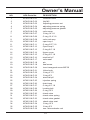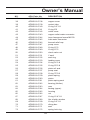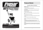
1
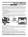
Pressure Washer
Important Safety Instructions
WARNING – When using this product basic precautions should always be followed,
including the following:
1. Read all the instructions before using the product.
2. To reduce the risk of injury, close supervision is necessary when a product is
used near children.
3. Know how to stop the product and bleed pressures quickly. Be thoroughly
familiar with the controls.
4. Stay alert – watch what you are doing.
5. Do not operate the product when fatigued or under the influence of alcohol or
drugs.
6. Keep operating area clear of all persons
7. Do not overreach or stand on unstable support. Keep good footing and balance
at all times.
8. Follow the maintenance instructions specified in the manual.
“WARNING – Risk of Injection or Injury– Do Not Direct Discharge Stream At
Persons.”
1. “WARNING: If you do not follow these instructions exactly, a fire or explosion
may result causing property damage, personal injury or loss of life.”
2. “In the event of pilot outage, wait at least five minutes to clear out any gas before
relighting.”
3. “Use only your hand to push in or turn the gas control knob. Never use a tool. If
the knob will not push in or turn by hand, don’t try to repair it; call a qualified service
technician.”
1
Pressure Washer
Table of Contents
Page
Topic
Safety Guidelines-Definitions
3
General Precautions
4
Assembly/Start-up
7
Maintenance
11
Trouble Shooting
14
Warranty
16
Parts List
18
2
Owner’s Manual
Warning! Read And Understand All Safety Precautions In
This Manual Before Operating. Failure To Comply With
Instructions In This Manual Could Result In Personal
Injury, Property Damage, And / Or Voiding Of Your
Warranty. All Power America Will Not Be Liable For Any
Damage Because Of Failure To Follow These Instructions.
Safety Symbols
The following symbols are used throughout this manual. Follow listed instructions to
ensure your safety.
DANGER
Indicates an imminently hazardous situation
which, if not avoided will result in serious
injury or even death.
WARNING
Indicates an imminently hazardous situation
which, if not avoided will result in serious
injury or even death.
CAUTION
Indicates a potentially hazardous situation
exists, which if not avoided, may result in
minor or moderate injury or product damage.
NOTE
Indicates operation or maintenance information helpful to improve performance
or operation.
3
Owner’s Manual
Pressure Washer
The following safety precautions apply whenever using, storing, or servicing your
pressure washer to reduce the possibility of personal injury.
Overlooking or ignoring these precautions can lead to personal injury or product
damage.
• Read this manual carefully. Know your equipment. Consider applications, potential
hazards and limitations for your unit.
• This equipment is designed for specific applications. Do not modify or use for any
application other than which it is designed for.
• Store the pressure washer in a well ventilated area with the fuel tank empty. Fuel
should not be stored near the pressure washer.
• Never operate pressure washer under these conditions:
a. A noticeable change in engine speed.
b. A noticeable loss of pressure.
c. Engine misfires.
d. Smoke or flames are present.
e. Enclosed area.
f. Excessive vibration.
g. Rain or bad weather.
• Water spray must never be directed towards people, pets, electric wiring, or directly
towards the pressure washer.
• Do not allow the hose to come in contact with the hot muffler
• Equipment must be placed on a firm supporting surface.
• Remove the spark plug or cable from the spark plug to prevent accidental starting
when not in use, or prior to detaching the high pressure hose.
4
Owner’s Manual
General Precautions (cont’d)
• Keep the pressure washer clean and free of oil, mud and other foreign matter.
• Do not wear loose clothing, jewelry, or anything that may be caught in the engine.
• Never direct spray at people or animals.
• Never allow children to operate pressure washer at any time.
• Use both hands to control the wand.
• Do not touch the nozzle or water spray while operating.
• Wear safety goggles while operating.
• Only approved hoses and nozzles should be used.
• Do not kink the high pressure hose.
• All hose connections must be properly sealed.
• In extremely cold conditions, prior to starting be sure ice has not formed in any part of
the pressure washer.
• Use only recommended chemicals.
• Outdoor use only.
• Place pressure washer away from cleaning site during operation.
• To prevent accidental discharge, the spray gun should be secured by locking the
trigger when not in use.
• Do not run the pressure washer more than 5 minutes without depressing the trigger
or damage to the pump may occur.
• Check the pressure washers periodically for damage, leaks or signs of deterioration.
All defects should be corrected before operating the pressure washer.
5
Owner’s Manual
General Precautions (cont’d)
• Do not touch hot muffler.
• Service, operate and refuel under the following conditions:
a. Good ventilation
b. Refuel the pressure washer in a well lit area.
c. Avoid fuel spills and never refuel while the pressure washer is running.
d. Avoid any ignition source when refueling.
e. Use lead free fuel with a minimum of 85 octane.
• Do not smoke near pressure washer.
• Do not operate under 40º fahrenheit.
Safety Features
THERMAL RELIEF VALVE
A thermal relief valve is provided to protect the pump from overheating if the spray gun is
closed for an extended amount of time or the nozzle becomes plugged. However, it is
intended to be used as a backup system and every effort should be made to not permit the
pump to heat up.
We recommend to turn the pressure washer OFF if it will not be used for more than 5
minutes. This saves wear on the unit, reduces fuel consumption and extends the life
of the pump by avoiding overheating.
SAFETY LOCK LATCH
To prevent accidental discharge of high pressure water, the safety latch on the trigger
should be engaged whenever the pressure washer is not in use.
LOW-OIL SHUTDOWN
Some engines are equiped with low-oil shutdown systems. If the engine oil level becomes
lower than required, the pressure washer wil automatically shut off. Refer to the engine
manual for this feature. This protects your pressure washer engine from operating without
proper lubrication.
If the pressure washer engine shuts off and the oil level is according to specification,
check to see if the pressure washer is sitting on an angle that forces the oil to shift.
Place on even surface to correct this. If the engine fails to start, there may not be enough
oil to deactivate the low oil level switch.
Pump will overheat and may be damaged,
or cause damage if allowed to circulate
more than 5 minutes
6
Owner’s Manual
Before Operation
NOTE: The engine and pump on your pressure washer will often have improved
performance after a break-in period of several hours.
PRE-START PREPERATION
Before starting the pressure washer, check for loose or missing parts and for any
damage which may have occured during shipping.
Assembly & Start-Up
HOSE & GUN ASSEMBLY
NOTE: Align threaded connections carefully to prevent damaging threads during
assembly. Tighten connections securely to prevent leaks during operation.
Wand
Gun
Attach the hose to the inlet on the trigger.
Hose
LUBRICATION
Do not attemp to start the pressure washer engine without filling the engine crank case
with the proper amount of oil. Your pressure washer has been shipped without oil in the
crankcase. Operating the pressure washer without oil will ruin the engine. Use oil that is
recommended (10W-30). DO NOT OVERFILL!
FUEL
Fill the tank with unleaded gasoline. Regular gasoline may be used provided a high
octane rating is obtained (at least 85 octane).
Gasoline is highly flammable and explosive
and you can be burned or seriously injured
when refueling if not carefull.
7
Owner’s Manual
Operating Connections
HIGH PRESSURE HOSE
• Attach the high pressure hose to the pressure washer by pulling back on the collar of
the quick-connect coupling on the hose and pushing it over the coupling half on the
pressure washer outlet.
NOTE: Do not use pressure hose from another manufacturer.
WATER CONNECTION
Before connecting the garden hose to your pressure washer, run water through the
garden hose (not supplied) to flush out any foreign matter.
• Attach garden hose quick-connect to the garden hose (see below).
• Then attach that to the quick-connect inlet on the pressure washer pump. Make sure
it locks into place by pulling back on the garden hose quick-connect collar and
inserting it into the quick-connect inlet.
NOTE: The water supply must supply a minimum of 4 gpm at 20 PSI, or the pump
can be damaged.
Detergent Connection
PRESSURE WASHER PUMP
8
Owner’s Manual
Operating Instructions
Start-up Procedure
1. Make sure water supply is connected and turned on.
2. Release gun safety if locked.
3. To allow air to escape from the hose, squeeze trigger on the gun until there is a
steady flow of water coming out from the nozzle.
Starting Engine
1. Check oil and gas.
2. Connect hose and turn on water.
3. Squeeze trigger.
4. Make sure the engine switch is on the ON position (illustration 1).
5. Set the fuel valve to open (illustration 2).
6. Set choke to CLOSE position (illustration 3) & set throttle to slow (illustration 4).
7. When starting engine, pull cord slowly until resistence is felt, then pull rapidly.
8. If engines starts and fails to continue running or if increase resistance is felt during
starting pull attemps repeat step 3 - 7.
1) ON/OFF Switch
2) Fuel Valve
3) Choke
4) Throttle Control
9
Owner’s Manual
CAUTION
This pressure washer is intended for use only with liquid car wash detergents,
developed specifically for pressure washers and with mild soaps. Only use chemicals
compatible with the aluminum and brass parts. Powdered soaps may clog the injection
system. Always use chemicals according to the manufacturers directions. We assume
no responsiblity for any damages caused by chemicals injected through this pressure
washer.
1. Attach injection tube assembly to the detergent connection on the pump. Assembly
instruction(BELOW).
2. Pour the two kinds of detergents into the detergent bottles. It is recommend to have
one detergent bottle filled with allpurpose detergent, and the other filled with a more
specific cleaning detergent.
3. The indicator on the detergent dial shows the amount and the consumption of
detergent Fig A.
4. Remove the high pressure nozzle from the wand and install the black injection nozzle.
The solution will automatically mix with the water and discharge through the nozzle.
NOTE: For certain models, if the engine throttle is not in the fast position, the injection
of the solution may be decreased or stopped.
Detergent
Connection
Detergent
Hose
From out of
Detergent Bottle
Fig A
CLEANING TECHNIQUES
When cleaning with the pressure washer, many cleaning tasks can be solved with water
alone, but for most tasks, it is advantageous to use a detergent. A detergeng ensures a
quick soaking of the dirt allowing the high pressure water to penetrate and remove the
dirt more effectively.
APPLICATION OF SOAP OR DEGREASER
1. Apply the solution to the dry work surface. On a vertical surface, apply horizontally
from side to side starting from bottom to avoid streaking.
NOTE: Wetting the surface first is not recommended, it dilutes the detergent and
reduces its cleaning effects. Please disconnect the Detergent Hose from the Pump
when do not use the detergent, and let the pressure washer run until you no longer
notice detergent coming out of the wand.This will prevent detergent from gumming up
the wand and reducing pressure for next use.
10
Owner’s Manual
Operation
Avoid working on hot surfaces or in direct sunlight to minimize the chances of the
chemical damaging painted surfaces. Damage may occur to painted surfaces if the
chemical is allowed to dry on the surface. Hold the nozzle far enough away from surface
to prevent damage to the surface.
2. Allow chemical to remain on the surface for a short time before rinsing.
3. Rinse with clean water under high pressure. On a vertical surface, first rinse from
the bottom up, then rinse from top down. Hold nozzle 6 to 8 inches from the work surface
at a 45° angle using the flat spray as a peeling tool rather than a scrub brush.
APPLICATION OF WAX
1. Immediately after cleaning, apply wax. Place injection tube in container of wax.
2. Apply the wax sparingly in an even layer. Apply to wet surfaces from bottom up for even
distribution and to avoid streaking.
3. Remove the suction tube from the wax bottle rinse off the surplus wax.
NOTE: If surplus wax is not removed, a hazy finish may result.
4. Wipe dry to reduce water spotting.
END OF OPERATION
When you have completed use of chemical injection system, remove tube from container.
Continue to run in low pressure position and inject clean water through the tube and
injection system by placing end of tube in a container of clean water. Continue to run
until it is thoroughly cleaned.
Maintenance
CONNECTIONS
Connection on pressure washer hoses, gun and spray wand should be cleaned
regularly and lubricated with the manufacturers recommended grease to prevent leakage
and damage to the O-ring.
NOZZLE
Clogging of the nozzle causes the pump pressure to be too high, cleaning is immediately
required.
A nozzle cleaner must only be used when the spray
wand is disconnected from the gun or personal injury
may occur.
1. Seperate the wand from the gun.
11
Owner’s Manual
Maintenance
2. Clear the nozzle with a small rigid piece of wire such as a paper clip.
3. Flush the nozzle backwards with water.
4. Reconnect the wand to the gun.
Restart the pressure washer and depress the trigger on the spray gun. If the nozzle is still
plugged or partially plugged, repeat above instructions 1-4.
If the previous procedure does not clear the nozzle, replace with a new nozzle.
ENGINE MAINTENANCE
During the winter months, rare atmospheric conditions may develope which will cause
an icing condition in the carburetor. If this develops, the engine may run rough, lose
power and may stall. This temporary condition can be overcome by deflecting some of the
hot air from the engine over the carburetor area.
Storage
PUMP STORAGE
If you must store your pressure washer in a location where the temperature is below 32° F,
you can minimize the chance of damage to your machine by utilizing the following
procedure:
1. Shut off water supply and relieve pressure to the spray gun by depressing the trigger.
Disconnect the garden hose from the pressure washer, but leave the high pressure hose
connected.
2. Tip the unit on its side with the inlet connection pointing up.
3. Insert a small funnel (to prevent spilling) into the inlet and pour in approximately 1/4 cup
of antifreeze.
4. Disconnect spark plug wire.
5. Without connecting garden hose pull the recoil several times to criculate the antifreeze
in the pump system.
6. Disconnect spark plug wire.
CAUTION
Prior to starting, thaw out any possible ice from the pressure washer hoses, spray gun
and wand.
12
Owner’s Manual
Maintenance
Another method of reducing risks of freeze damage is to drain your pressure washer as
follows:
1. Stop the pressure washer and detach supply hose and high pressure hose. Squeeze
the trigger of the discharge gun to drain all water from the wand and hose.
2. Restart the pressure washer and let it run briefly about 5 seconds) until water no
longer discharges from the high pressure outlet.
Engine Storage
When the pressure washer is not being used or is being stored for more than a month
follow these instructions:
1. Replenish engine oil to upper level.
2. Drain gasoline from fuel tank, fuel line, fuel valve and carburetor.
3. Pour about one teaspoon of engine oil through the sparkplug hole, pull the recoil
starter slowly until you feel increase pressure which indicates the piston is on its
compression stroke and leave it in the position. This closes both the intake and exhaust
valves to prevent the inside of the cylinder from rusting.
4. Cover the pressure washer and store in a clean, dry place that is well ventilated
away from open flame or sparks.
NOTE: The use of a fuel additive, such as STA-BIL, or an equivalent, will minimize
the formulation of fuel gum deposits during storage.
Technical Specification
Maximum Inlet Pressure
Maximum Pressure
Rated Flow
Engine Model
Displacement
RPM
Fuel Tank
Temperature OF Pumped Fluids
Inlet Ports
Discharge Ports
Weight
Engine Oil
Fuel
Up To 90 PSI
3200 PSI
2.6 GPM
JF210
208 cc
3600 RPM
0.95 gallon
Up To 80
(2) 1/2 inch BSP
(2) 1/2 inch BSP
81.6 lbs.
10W-30
Unleaded Gas
13
Owner’s Manual
Trouble Shooting
• Engine wil not start or stops while operating.
Low-oil shutdown:
Engine switch not in “ON” position:
Pressure built up in hose:
Fill engine with oil
Turn switch “ON”S
Squeeze trigger while starting
• Engine is overloaded
Nozzle partially blocked
Excessive pressure
Clean Nozzle
Shorten the spring coil on the reflux valve
• Pressure increases when gun is locked
Bypass valve blocking
Clean the bypass valve
• Engine is running but pump won’t build maximum pressure or has irregular pressure
Faucet closed
Open faucet
Unit has been stored in freezing temp. Thaw out unit completely
Inadequate water supply
Provide a minimum of 4 GPM at 20 PSI
Water inlet screen clogged
Clean screen
Kink in garden hose
Straighten garden hose
Wand nozzle worn or damaged
Replace nozzle
Air in pump
Run with gun open & wand removed
until steady stream of water is released
Adjustable pressure knob not set
Set to maximum position
to maximum position
Suction or discharge valves clogged
Clean the suction or discharge valves
or worn out
Bypass valve not operating effectively Clean the bypass valve
• No intake of chemicals
Injection tube not securely inserted
into unit
Tube cracked or split
Wrong nozzle
Injector turned off
Replace tube
Switch to low pressure nozzle
Turn collar counter
• Trigger will not move
Gun safety lock engaged
Release safety lock
14
Push firmly into injector
Owner’s Manual
Trouble Shooting
• Water in crankcase
High humidity
Worn seals
• Noisy operation
Worn bearings
Air mixed with water
Change oil more frequently
Change the oil seals
Change the bearings
Check inlet lines for restrictions
and / or proper sizing
• Rough / pulsating, operating with pressure drop
Inlet restriction
Check system for stoppages, air leaks,
correctly sized inlet plumbing to pump
Unloader
Check unloader for proper operation
Air mix in water
Check inlet lines for restrictions and or
proper sizing
• High crankcase temperatures
Wrong grade of oil
Improper amount of
oil in crankcase
Use recommended oil
Adjust oil to proper amount
15
Owner’s Manual
Limited Warranty
All-Power America warrants to the original purchaser who uses the product in a
consumer application (personal, residential or household usage) that all products
covered under this warranty are free from defects in material and workmanship for one
year from the date of purchase. All products covered by this limited warranty which are
used in commercial applications (i.e. income producing) are warranted to be free of
defects in material and workmanship for 90 days from the date of original purchase.
Products covered under this warranty include air compressors, air tools, service parts,
pressure washers and generators.
All-Power America will repair or replace, at All-Power America’s sole option, products
or components which have failed within the warranty period. Service will be scheduled
according to the normal work flow and business hours at the service center location,
and the availability of replacement parts. All decisions of All-Power America with regard
to this limited warranty shall be final.
This warranty gives you specific legal rights, and you may also have other rights which
vary from state to state.
RESPONSIBILITY OF ORIGINAL PURCHASER (initial User):
To process a warranty claim on this product, DO NOT return item to the retailer. The
product must be evaluated by an Authorized Warranty Service Center. For the location
of the nearest Authorized Warranty Service Center contact the retailer or place of
purchase.
Retain original cash register sales receipt as proof of purchase for
warranty to work.
Use reasonable care in the operation and maintenance of the product as described in
the Owner’s Manual(s).
Deliver or ship the product to the Authorized Warranty Service Center. Freight costs, if
any must be paid by the purchaser.
If the purchaser does not receive satisfactory results form the Authorized Warranty
Service Center, the purchaser should contact All-Power America.
16
Owner’s Manual
Limited Warranty (cont’d)
THIS WARRANTY DOES NOT COVER:
• Merchandise sold as reconditioned, used as rental equipment, or floor or display
models.
• Merchandise that has become damaged or inoperative because of ordinary wear,
misuse, cold, heat, rain, excessive humidity, freeze damage, use of improper chemicals,
negligence, accident, failure to operate the product in accordance with the instructions
provided in the Owner’s Manual(s) supplied with the product, improper maintenance,
the use of accessories or attachments not recommended by All-Power America, or
unauthorized repair or alterations.
• Repair and transportation costs of merchandise determine not to be defective.
• Costs associated with assembly, required oil, adjustments or other installation and
start-up costs.
• Expendable parts or accessories supplied with the product which are expected to
become inoperative or unusable after a reasonable period of use.
• Merchandise sold by All-Power America which has been manufactured by and
identified as the product of another company, such as gasoline engines. The product
manufacturer’s warranty, if any, will apply.
• ANY INCIDENTAL, INDIRECT OR CONSEQUENTIAL LOSS, DAMAGE, OR
EXPENSE THAT MAY RESULT FROM ANY DEFECTS, FAILURE OR
MALFUNCTION OF THE PRODUCT IS NOT COVERED BY THIS WARRANTY.
Some states do not allow the exclusion, so it may not apply to you.
• IMPLIED WARRANTIES, INCLUDING THOSE OF MERCHANTABILITY OR
FITNESS FOR A PARTICULAR PURPOSE, ARE LIMITED TO ONE YEAR FROM
THE DATE OF ORIGINAL PURCHASE. Some states do not allow limitations on how
long an implied warranty lasts, so the above limitations may not apply to you.
Distributed by:
ALL-POWER AMERICA
www.allpoweramerica.com
17
Owner’s Manual
PARTS and PARTS LIST
18
Owner’s Manual
NO.
APA Parts No.
1
2
3
4
5
6
7
8
9
10
11
12
13
14
15
16
17
18
19
20
21
22
23
24
25
26
27
28
29
30
31
32
33
34
35
36
37
38
39
40
41
42
43
APW5118-YG-01
APW5118-YG-02
APW5118-YG-03
APW5118-YG-04
APW5118-YG-05
APW5118-YG-06
APW5118-YG-07
APW5118-YG-08
APW5118-YG-09
APW5118-YG-10
APW5118-YG-11
APW5118-YG-12
APW5118-YG-13
APW5118-YG-14
APW5118-YG-15
APW5118-YG-16
APW5118-YG-17
APW5118-YG-18
APW5118-YG-19
APW5118-YG-20
APW5118-YG-21
APW5118-YG-22
APW5118-YG-23
APW5118-YG-24
APW5118-YG-25
APW5118-YG-26
APW5118-YG-27
APW5118-YG-28
APW5118-YG-29
APW5118-YG-30
APW5118-YG-31
APW5118-YG-32
APW5118-YG-33
APW5118-YG-34
APW5118-YG-35
APW5118-YG-36
APW5118-YG-37
APW5118-YG-38
APW5118-YG-39
APW5118-YG-40
APW5118-YG-41
APW5118-YG-42
APW5118-YG-43
DESCRIPTION
Detergent bottle switch
Spring Lock
Detergent bottle cap
Detergent bottle gasket
Upper frame Assy.
Crosshead bolt M5*45
Gasket φ5
Hose hook
High pressure hose
Detergent bottle
Crosshead bolt M5*12
Injection hose
inner hexagonal bolt M8*25
Spring gasket φ8
Gasket φ8
pump
Drain hose
Thermal relief cap
Crosshead bolt M5*40
Locknut M5
Nether frame Assy.
Crosshead bolt M6*45
10" wheel
Locknut M8
Rubber foot
Inner hexagonal bolt M8*50
Inner hexagonal bolt M8*40
Gasket φ6
Locknut M6
Axle buckle
Spring wire
Wheel shaft
Gasket φ16
Circlip
Gun tip holder
Engine foot
Engine
Gun holder
Crosshead bolt M5*55
High pressure gun
Nozzle
Nozzle gromet
Detergent bottle wsitch nut
19
QTY.
1
5
2
2
1
2
13
1
1
2
2
3
4
4
14
1
1
1
6
9
1
4
2
6
2
2
4
5
5
2
2
2
2
2
1
1
1
1
1
1
5
5
1
Owner’s Manual
PUMP ( G-37 )
20
Owner’s Manual
NO.
APA Parts No.
DESCRIPTION
1
APW5118-P-01
Overflow valve
2
APW5118-P-02
Nut M5
3
APW5118-P-03
Adjusting pressure nut
4
APW5118-P-04
adjusting pressure spring
5
APW5118-P-05
adjusting pressure gasket
6
APW5118-P-06
valve cover
7
APW5118-P-07
O ring 14*1.8
8
APW5118-P-08
O ring 12.4*1.8
9
APW5118-P-09
valve rod assy.
10
APW5118-P-10
open loop 1
11
APW5118-P-11
O ring 6.07*1.8
12
APW5118-P-12
Open loop 2
13
APW5118-P-13
O ring 8.6*1.8
14
APW5118-P-14
Upper cover
15
APW5118-P-15
O ring 9.5*1.8
16
APW5118-P-16
steel ball φ7
17
APW5118-P-17
valve seat
18
APW5118-P-18
pin
19
APW5118-P-19
seal screw
20
APW5118-P-20
inner hexagonal screw M5*30
21
APW5118-P-21
Valve body
22
APW5118-P-22
O ring 4*1.5
23
APW5118-P-23
O ring 8*2
24
APW5118-P-24
steel ball φ5
25
APW5118-P-25
injection spring
26
APW5118-P-26
drain hose
27
APW5118-P-27
O ring 4.5*1.8
28
APW5118-P-28
locating bolt
29
APW5118-P-29
O ring 15*2
30
APW5118-P-30
check valve
31
APW5118-P-31
check valve spring
32
APW5118-P-32
check valve gasket
33
APW5118-P-33
check valve seat
34
APW5118-P-34
O ring 12*2
35
APW5118-P-35
O ring 5*2
36
APW5118-P-36
non- returnedvalve rod
21
Owner’s Manual
NO.
APA Parts No.
DESCRIPTION
37
APW5118-P-37
non-returnedvalve spring
38
APW5118-P-38
copper cover
39
APW5118-P-39
venturi tube
40
APW5118-P-40
O ring 9.3*1.8
41
APW5118-P-41
O ring 8*2
42
APW5118-P-42
outlet cover
43
APW5118-P-43
copper outlet water connector
44
APW5118-P-44
inner hexagonal screw M8*50
45
APW5118-P-45
Inlet water connector
46
APW5118-P-46
thermal relief cap
47
APW5118-P-47
pump cover
48
APW5118-P-48
O ring 12*2
49
APW5118-P-49
O ring 15*2
50
APW5118-P-50
check valve nut
51
APW5118-P-51
Y seal
52
APW5118-P-52
seal ring
53
APW5118-P-53
leading cover
54
APW5118-P-54
O ring 14*2.8
55
APW5118-P-55
O ring 23*2.8
56
APW5118-P-56
piston oil seal
57
APW5118-P-57
pump seat
58
APW5118-P-58
O ring 75*2.8
59
APW5118-P-59
piston spring
60
APW5118-P-60
piston
61
APW5118-P-61
piston spring seat
62
APW5118-P-62
bearing (Nether)
63
APW5118-P-63
cam
64
APW5118-P-64
beaing (upper)
65
APW5118-P-65
housing
66
APW5118-P-66
nut
67
APW5118-P-67
O ring 15.4*1.8
68
APW5118-P-68
Alu oil side window
69
APW5118-P-69
O ring 9.3*1.8
70
APW5118-P-70
diving box
71
APW5118-P-71
seal
72
APW5118-P-72
spring lock ring
22