1
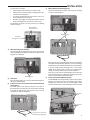
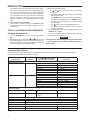
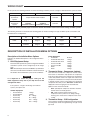
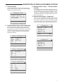
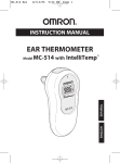
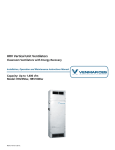
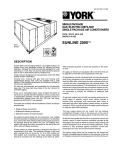
IntelliteMp™ 900
INStAllAtION INStRUCtIONS
Operator: Save these instructions for future use!
FAIlURe tO ReAd ANd FOllOW All INStRUCtIONS CAReFUllY BeFORe
INStAllING OR OpeRAtING tHIS CONtROl COUld CAUSe peRSONAl
INJURY ANd/OR pROpeRtY dAMAGe.
deSCRIptION
This IntelliTEMP™ thermostat replaces the following thermostats:
• HeatPump(NoAux.orEmergencyHeat)
• HeatPump(upto4H/2C)
• SingleStageHeat&CoolingSystems
• UptoTwoStageHeatorTwoStageCool
• HeatOnlySystems
• StandardCentralAirConditioning
• Hydronic(HotWater)ZoneHeat–2Wires
(ButnotHydroniczoneheatwith3wires)
SpeCIFICAtIONS
Electrical Rating:
Input-Hardwire ................................................... 20 to 30 VAC
TerminalLoad ........................................................... 1.5Aperterminal,2.0Amaximumallterminalscombined
Setpoint Range ......................................................... 45to99°F(7to37°C)
OperatingAmbient .................................................... 32°Fto+105°F(0to+41°C)
OperatingHumidity ................................................... 90%non-condensingmax.
Shipping Temperature Range ................................... -40to+150°F(-40to+65°C)
! CAUTION
to prevent electrical shock and/or equipment damage,
disconnect electric power to system at main fuse or
circuit breaker box until installation is complete.
CONteNtS
AtteNtION: MeRCURY NOtICe
This product does not contain mercury. However, this
productmayreplaceaproductthatcontainsmercury.
Mercury and products containing mercury must not be
discarded in household trash. Do not touch any spilled
mercury. Wearing non-absorbent gloves, clean up any
spilledmercuryandplaceinasealedcontainer.Forproper
disposal of a product containing mercury or a sealed
containerofspilledmercury,placeitinasuitableshipping
container. Refer to www.thermostat-recycle.org for
locationtosendproductcontainingmercury.
Description .......................................................................1
Specifications ...................................................................1
Installing the Thermostat ..................................................2
Wiring Chart .....................................................................6
Description of Installation Menu Options .........................7
!
WARNING
do not use on circuits exceeding specified voltage.
Higher voltage will damage control and could cause
shock or fire hazard.
pARt NO. 37-7224B
Replaces 37-7224A
1211
INSTALLATION
Required Parts
•
•
•
Thermostat (1)
Wall anchors (2)
Mounting screws (2)
Required Tools
Quick Guide
1) Remove the old thermostat
• Turn off power at the breaker.
To prevent electrical shock and/or equipment damage,
disconnect electric power to system at main fuse or
circuit breaker box until installation is complete.
•
•
2)
3)
4)
5)
Remove cover from old thermostat to expose wires.
Identify each wire to corresponding terminal and disconnect.
• Remove old thermostat from wall, making sure that
thermostat wires do not fall back into wall opening.
Mount the new thermostat
• Feed thermostat wires through thermostat hole.
• Feed antenna wire through wall opening.
• Wire new thermostat.
• Turn on power at breaker.
Configure the thermostat
Check thermostat operation
Verify Communications
The sections that follow provide detailed instructions for completing these steps.
Step 1: Remove the Old Thermostat
Thermostat Components
The standard heat/cool thermostat normally consists of three
basic parts:
1. Cover.
2. Base, which you can remove by loosening all screws.
3. Switching sub-base or Mounting base, which you can remove
by unscrewing the mounting screws that hold it on the wall
or adaptor plate.
Remove the old thermostat:
1. Remove the front cover of the old thermostat.
2. With wires still attached, remove wall plate from the wall
by unscrewing it. If the old thermostat has a wall mounting
2
You may want to wrap the wires around a pencil to keep
them from falling back into the wall.
Y
+
R
+
G
+
+
C
+
W
G
! CAUTION
NOTE
W
Flat blade screwdrivers – 1 large and 1 small
Hand or power drill with 3/16 inch drill bit
Wire strippers
Level (optional)
Important: Do not let wires fall back into the wall.
C
•
•
•
•
plate, remove the thermostat and the wall mounting plate
as an assembly.
3. Identify each wire attached to the old thermostat as shown
in the diagram below. Before removing wires from old thermostat’s switching sub-base, label each wire with the letter
on the old thermostat. Ignore wire colors and use the letter
designation only.
4. Disconnect the wires from the old thermostat one at a time.
Y
Before you begin to install your IntelliTEMP™ thermostat:
• Read these instructions thoroughly.
• Check the package from your thermostat to make sure you
have all of the required parts (see below).
• Assemble the required tools (see below).
R
Pre-Installation Checklist
+
Figure 1. Thermostat wires with labels
Step 2: MOUNT THE NEW THERMOSTAT
! CAUTION
Take care when securing and routing wires so they do
not short to adjacent terminals or rear of thermostat.
Personal injury and/or property damage may occur.
To prevent personal injury and/or property damage,
contact Customer Service at your utility company
before attempting any step in the installation process
that you are unsure about how to perform.
Mount the new thermostat:
1) Unpack the thermostat and separate the mounting plate
from the thermostat.
Remove the packing material from the thermostat. Gently
pull the thermostat straight off of the base: hold the thermostat from the back by the lower corners with one hand,
and pull the mounting plate off with the other hand.
NOTE
Forcing or prying on the thermostat will cause damage to
the unit.
2) Feed thermostat wires through rectangular hole between
the terminal blocks in the thermostat mounting plate.
3) Connect wires to the thermostat mounting plate.
Connect wires beneath terminal screws on base. The photo on next page shows the location of the wire terminals in the
IntelliTEMP™ 900. There are two sets of terminals on either
side of the hole the wires are fed through. Each terminal is
labeled with a letter or a letter with a number (O, B, R, etc.).
INSTALLATION
Connect wires as follows:
• Strip insulation about 3/8 inch from end of wire.
• Feed thermostat wires through rectangular hole in the
thermostat mounting plate.
• Locate the terminal that the wire needs to connect to.
Use the Wiring Chart on page 6.
• Bend the wire slightly, insert the wire between contact
plates, and tighten the screw down onto the wire.
For full details on where to connect each wire, see “Wiring
Chart” on page 6.
7) Mount thermostat mounting plate.
Fasten mounting plate loosely to wall using two mounting
screws in mounting holes.
Wire terminals.
Insert wires here
Mounting holes
Feed wires
through this hole
4) Mark mounting hole locations.
Place thermostat mounting plate over hole in the wall and
mark mounting hole locations (see below) using the mounting plate as a template.
Mounting holes
5)Drill holes.
Move mounting plate out of the way. Drill mounting holes
using a 3/16 inch drill bit.
6) If device has wire, uncoil antenna wire and feed through
wall opening.
The white antenna wire will be coiled up on the back of
the thermostat. Uncoil the wire (as shown below) and feed
it through the wall opening. This antenna wire is used to
communicate with the thermostat.
If desired, place a level against bottom of the mounting plate
and adjust until level before tightening screws. (Leveling is
for appearance only and will not affect thermostat operation.)
If you are using existing mounting holes, or if the holes
drilled are too large and do not allow you to tighten base
snugly, use plastic wall anchors to secure sub-base.
Push excess wire into the wall and plug the hole with a fire
resistant material (such as fiberglass insulation) to prevent
drafts from affecting thermostat operation.
8) Fasten Thermostat to Mounting plate
The IntelliTEMP™ is designed with a quick connect feature
between the thermostat unit and mounting plate. When
installing the thermostat onto the mounting plate, make
sure the retention tabs on the mounting plate are in line with
Retention
slots
Retention
tabs
Uncoil wire as shown and
feed through wall opening
3
INSTALLATION
the retention slots in the thermostat (see previous page). Gently press the thermostat onto the mounting plate until
you hear the retention tabs make a clicking sound and
the thermostat is securely fastened to the mounting plate. If the thermostat does not easily click onto the mounting
plate, be certain not to press with excessive force or else
damage could occur to the thermostat and/or mounting
plate.
9)Turn power back On at breaker.
When power is applied, verify the IntelliTEMP™ 900
thermostat powers up and begins to display the room
temperature.
Step 3: configure the new thermostat
Configure the thermostat:
1. Press the SYSTEM button until the system mode displays
OFF.
2. Simultaneously press and hold the and buttons to enter
the Installation Menu. First screen asks for confirmation to enter the installation menu. Once confirmed, the display will
show the first level of the Installation Menu.
3. While in the Installation Menu:
and
buttons scroll the cursor up and down
• the
respectively
• The DONE softkey will confirm changes saved and go
back one menu level.
• The HOME softkey exits the installation menu back to
the IDLE screen (NOTE: When the HOME softkey is
pressed, any changes made on the current menu item
are not saved).
• The
button selects the highlighted menu item
• The DONE softkey goes back one menu level if no
changes were made.
4. To exit the menu and return to the program operation, press
HOME (when available).
If no keys are pressed within two minutes, the thermostat
will revert to normal operation.
NOTE
It is important to select the proper setting for the first item
on the configuration menu which specifies the type of
HVAC system.
Installation Menu Options
The installation menu table summarizes the configuration options. For more details on each Installation Menu option, see
“Description of Installation Menu Options” on page 7.
Menu Name
Submenu
Press
or
to Select Other
Options (Defaults in BOLD)
Comments
HVAC Equipment Setup
Outdoor
Indoor
Thermostat Setup
Compressor Lockout
O/B Configuration
Thermostat Data
Firmware:
Hardware Model:
S/N:
Communications Setup
Device Information
WAN Interface
4
Air Conditioner
Air Conditioner
Heat Pump
Heat Pump
Heat Pump
Heat Pump
None
Air Handler
Air Handler
Air Handler
Furnace
Furnace
Boiler
Boiler
On
Off
O: Cool
B: Heat
1 Stage
2 Stage (default)
Air - 1 Stage
Air - 2 Stage
Geo - 1 Stage
Geo - 2 Stage
No Heat
Elec Heat - 1 Stage
Elec Heat - 2 Stage
Gas / Oil - 1 Stage
Gas / Oil - 2 Stage (default)
1 Stage
1 Stage
INSTALLATION
Step 4: CHECK THERMOSTAT OPERATION
! CAUTION
To prevent possible compressor and/or property damage, if the outdoor temperature is below 55oF, DO NOT
operate the cooling system.
Once you have installed your new IntelliTEMP™ thermostat, you
need to check that the fan, cooling system, and heating system
are all operating properly.
Check Fan Operation
1. Press the SYSTEM button one or more times to select OFF.
2. Press the FAN button. Ensure the message FAN ON is displayed on the thermostat display. The blower should begin
to operate. Place your hand by a vent to confirm blower is
running.
2. Press the FAN button again. Ensure the FAN ON message
is no longer displayed. The blower should stop immediately.
Check the Cooling System
Note: If system has 2 or more stages of heating and cooling,
confirm thermostat settings menu item #7 is set to “Comfort”.
1. Press the SYSTEM button one or more times to select
COOL.
2. Press the
button to adjust thermostat setting 1° below
room temperature. The outdoor unit should energize almost
immediately in cooling mode and the indoor blower fan
should energize within a minute of the start of the call for
cool (depends on system configuration). The display should
show “COOL1”. NOTE: If compressor lockout is set to ON,
the thermostat will not call for cool until after the 5 minute
safety time period and will display the message A/C return
< 5 min. After the 5 minutes expire the thermostat will call
for cool.
3. If the system is a multi-stage cooling system, adjust the
temperature setting to at least 3° below room temperature.
The second stage cooling should begin to operate and the
display should show “COOL2”.
4. Press the button to adjust the temperature setting above
room temperature.The cooling system should stop operating
within a minute (depends on system configuration).
Check the Heating System
1. Press SYSTEM button one or more times to select HEAT
mode.
2. Press the button to adjust thermostat setting to 1° above
room temperature. The heating system should begin to
operate. “HEAT1” should display. NOTE: If the system is
configured as a heat pump and compressor lockout is set
to ON, the thermostat will not call for heat until after the 5
minute safety time period and will display the message A/C
return < 5 min. After the 5 minutes expire the thermostat
will call for heat.
3. If the system is a multi-stage heating system, adjust the
temperature setting to at least 3° above room temperature.
The second stage of the heating should begin to operate
and “HEAT2” should display. For Heat Pump systems with
AUX heat configured, within a very short time the AUX heat
should begin to operate and “HEAT3” then “HEAT4” (for
multi-stage AUX system only) will be displayed.
4. Press the
button to adjust the thermostat below room
temperature. The heating system should stop operating.
Check the AUX heating system (Heat Pump
systems only):
The Auxiliary Heat bypasses the Heat Pump to use the heat
source wired to E & W2 terminals of the thermostat. AUX is
typically used when compressor operation is not desired, the
user prefers to utilize the back-up heat only or the compressor
is not able to satisfy the demand for heat to the user’s desire.
1. Press SYSTEM button one or more times to select AUX
mode.
2. Press the button to adjust thermostat setting to 1° above
room temperature. The AUX heating system should begin
to operate. “AUX1” should display.
3. If the system is a multi-stage AUX heating system, adjust the
temperature setting to at least 3° above room temperature.
The second stage AUX heat should energize and “AUX2”
should be displayed.
4. Press the
button to adjust the thermostat below room
temperature. The heating system should stop operating
within 1 minute (depends on system configuration).
Return thermostat settings to “Economy mode” if changed
to “Comfort mode” to check system.
Step 5: Verify Paging Communications
Note: Only for paging systems
From the installer’s menu, select the Diagnostics Display. If the
IntelliTEMP™ 900 is able to correctly receive pages from the
utility Head-End, the TC (Test Count) value should increment
by one count at the rate at which the local utility sends out the
test light off command (typically every 3 minutes).
5
WIRING CHART
For all systems, the following terminals are wired according to whether you have a single or dual transformer system as shown:
RH
Single
Transformer
System
Dual
Transformer
System
RC
24 VAC Hot
Jumper should remain installed
24 VAC – Heat
*REMOVE
PROVIDED JUMPER
24 VAC – Cool
*REMOVE
PROVIDED JUMPER
C
L
G
24 VAC
Common
Malfunction Light
Blower/Fan
24 VAC
Common
Malfunction Light
Blower/Fan
*Failure to remove provided jumper on dual transformer installations could cause severe damage to HVAC systems.
The following terminals on the thermostat mounting plate are wired according to the type of HVAC system connected to and
the thermostat is configured as.
Y1
Y2
W/E
W2
O/B
Conventional
HVAC
Cool Mode
Stage 1
Cool Mode
Stage 2
Heat Mode
Stage 1
Heat Mode
Stage 2
-
Heat Pump
Compressor
Contactor
Compressor
Stage 2
AUX Heat
Stage 1
AUX Heat
Stage 2
Reversing Valve
DESCRIPTION OF INSTALLATION MENU OPTIONS
Description of Installation Menu Options
Indoor Equipment
• Air Handler
• Air Handler Elec Heat
• Air Handler Elec Heat
• Furnace Gas/Oil • Furnace Gas/Oil • Boiler • Boiler Following are detailed descriptions of the configuration menu
options.
1. HVAC Equipment Setup
This menu item specifies the system configuration. Outdoor
and indoor systems can be configured up to two stages
each.
Note: If Heat Pump is selected as the Outdoor system Indoor
selections are limited to Air Handler. A selection other than
Air Handler will revert Outdoor system to Air Conditioner.
2.Thermostat Setup – Compressor Lockout
This menu item controls the compressor lockout feature.
This feature is intended to help protect the compressor
from short cycling. Some newer compressors already have
a time delay built in and do not require this feature. Your
compressor manufacturer can tell you if the lockout feature
is already present in their system. When the thermostat
compressor time delay occurs, A/C return < 5 min will be
displayed on the messaging area of the thermostat.
Options for this menu item include:
NOTE
It is important to select the proper setting for the
HVAC equipment setup, even if you skip the rest of the
Configuration menu.
If the system is a single or multi-stage conventional
system, your options are:
Outdoor Equipment
• Air Conditioner
• Air Conditioner
• Heat Pump • Heat Pump • Heat Pump • Heat Pump 6
1 Stage
2 Stage
Air - 1 Stage
Air - 2 Stage
Geo - 1 Stage
Geo - 2 Stage
No Heat
1 Stage
2 Stage
1 Stage
2 Stage
1 Stage
2 Stage
•
•
OFF – (Default) No compressor wait time. Assumes lockout feature is already present.
ON – Waits 5 minutes before turning on the compressor after a power loss or during cooling/
heating cycles. Protects the compressor from short cycling.
3.Thermostat Setup – O/B Configuration
This configures whether the O/B terminal for the heat pump
reversing valve will be energized during cool (O) or heat
(B) mode.
DESCRIPTION OF INSTALLATION MENU OPTIONS
4.Thermostat Data
This screen provides the software version of the thermostat chassis firmware as well as the Hardware Model
number of the thermostat chassis.
<
6. Communications Setup – Communications
Interface
Thermostat Data
Firmware: 0160 0263
07
Hardware Model: 1F98-0600
S/N: XXXXXXXX
HOME
DONE
There will be a menu item(s) between the Device Information and Diagnostics menu items, dependent upon the
communication technology installed in the device. Please
reference the appropriate installation addendum for each
communication technology installed in the device for instructions on these menus.
7. Communications Setup – Diagnostics
This menu show diagnostic information relevant to this
device, such as the number of test count pages received,
the number of sheds the device has performed, the number
of cold starts (power loss), warm starts (microprocessor
restarts), total resets and a communications loss count.
Diagnostics
5. Communications Setup – Device Information
This menu shows the Comverge device information for
the thermostat communications interface board. This
screen displays the system serial number, system model
number, the communications interface board firmware
version, rate address information and manufacturing
populated information.
Test Cnt
Shed Cnt
Cold Start
Warm Start
Resets
HOME
1,246
0
25
72
97
DONE
Device Information
S/N:
Model:
FW:
Rate:
A1:
HOME
123,454,321
IT-900
01-10_1224
0
0
Diagnostics
DONE
Device Information
FW
Rate
A1
A2
A3
HOME
01-10_1224
0
0
0
0
Shed Cnt
Cold Start
Warm Start
Resets
Comm Loss
HOME
0
25
72
97
0
DONE
DONE
Device Information
A3
A4
A5
HW
MFG
HOME
0
0
0
FFFF
080917
DONE
7
IntelliTEMP™ is a registered trademark of Comverge, Inc.
The Comverge logo is a trademark of Comverge, Inc.