1
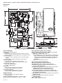
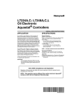
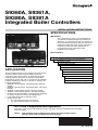
S9360A, S9361A,
S9380A, S9381A
Integrated Boiler Controllers
INSTALLATION INSTRUCTIONS
SPECIFICATIONS
IMPORTANT:
The specifications given in this publication do
not include normal manufacturing tolerances.
Therefore, an individual unit may not match the
listed specifications exactly. Also, this product is
tested and calibrated under closely controlled
conditions, and some minor differences in
performance can be expected if those
conditions are changed.
Model Numbers
APPLICATION
These integrated boiler control modules provide ignition
sequence, flame monitoring and safety shutoff for
intermittent pilot spark ignition, or direct spark ignition
heating systems. They also provide limit rated water
temperature control with one or two sensors and display
interface capability for either “on-board” or remote user
interface applications.
• S9360A—Spark Ignition, Intermittent Pilot, Remote
Display.
• S9361A—Spark Ignition, Intermittent Pilot, “On board”
Display.
• S9380A—Direct Spark Ignition, Remote Display.
• S9381A—Direct Spark Ignition, “On board” Display.
• Enabled with EnviraCOM™ communication capability
to support remote monitoring and diagnostics.
• Limit-rated Temperature Sensing Probe.
• Ignitor sensor type
— two rod (separate ignitor and sensor)
— one rod (combined ignitor and sensor)
S—Switching Control
9 3—Integrated Hydronic Control Platform
6—Spark Ignition
8—Direct Spark Ignition
0—Remote Display Required
1—Integrated On-Board Display
A—Boiler Control
B—Water Heater Control
C—Pool Heater Control
1—No Circulator
2—On/Off Circulator
3—On/Off Circulator meeting CSD-1
2012 DOE Compliance and Operation
Operation of this control may delay the burner operation while the residual heat is circulated
out of the boiler.
NOTE:
This operation may be different than earlier integrated boiler control
revisions which did not implement thermal purge.
66-1203-03
S9360A, S9361A, S9380A, S9381A INTEGRATED BOILER CONTROLLERS
Dimensions:
See Fig. 1.
I
111
2 x 61
2 x 84.5
220.5
2 x 15
2 x 15
1-3/8
(35)
5/8
(16)
M24217
Fig. 1. S936X Integrated Boiler Controller, dimensions in in. (mm).
Electrical Ratings:
Line Voltage: 120 Vac, 60 Hz.
Transformer:
Nominal 24 Vac (maximum 30 Vac, minimum 18 Vac).
5.0 VA plus external loads (gas valve, vent damper, etc.)
On/Off Circulator:
Full Load: 7.4A at 120 Vac (0.75 to 0.8 power factor
[PF]).
Locked Rotor: 44.4A at 120 Vac (0.4 to 0.5 PF).
Inducer (Optional):
Full Load: 6A at 120 Vac (0.75 to 0.8 PF).
Locked Rotor: 17.48A at 120 Vac (0.4 to 0.5 PF).
Vent Damper (Optional):
Full Load: 0.5A at 24 Vac.
In Rush: 1A at 24 Vac.
Main Valve:
Full Load: 2A at 24 Vac (0.5 to 0.6 PF).
In Rush: 6A at 24 Vac (0.5 to 0.6 PF)
Pilot Valve (Optional):
Full Load: 2A at 24 Vac (0.5 to 0.6 PF)
In Rush: 6A at 24 Vac (0.5 to 0.6 PF).
Flame Monitoring (May vary by model):
Flame Establishing Period (FEP): Maximum 2 seconds.
Flame Failure Response Time (FFRT):
Maximum: 2 seconds @ 1 μA.
Flame Stabilization Time: 4 seconds. Time from igniting the main burner and detecting loss of flame (the
flame current is allowed to be under the flame lost
threshold for this time while waiting for burner to
stabilize).
Flame Lost Threshold: 0.23 μA.
Accessories (Ordered Separately)
W8735Y1000 Wireless Outdoor Reset Kit
W873ER1000 Wireless Outdoor Reset Module
C7089R1013 Wireless Outdoor Temperature Sensor
(requires W8735ER1000)
W8735S1000 AquaReset™ Outdoor Reset Kit (includes
50022037-002 Outdoor Reset Module and
C7089U1006 Outdoor Temperature Sensor)
W8735S1008 AquaReset™ Domestic Hot Water Kit
(includes 50022037-005 Domestic Hot Water Module
and 32003971-003 Sensor)
C7089U1006 Outdoor Temperature Sensor (used with the
50022037-002)
32003971-003 Temperature Sensor (used with
50022037-005)
Sensor (See Table 2).
Sensor Well Clamp 121371AA.
Ambient Ratings:
Humidity: 0 to 95 percent relative humidity,
noncondensing.
Operating Ambient Temperature: -4°F to +150°F.
Shipping Ambient Temperature: -40°F to +175°F.
66-1203—03
2
S9360A, S9361A, S9380A, S9381A INTEGRATED BOILER CONTROLLERS
Frequent Cycling
14,000,485-016 1/4 in. (6.35 mm) diameter, 1-1/4 in.
(31.75 mm) length glass cartridge Fuse, 1 A,
Slow-Blow.
120650 Heat Conductive Compound.
These controls are designed for use on domestic and
commercial boiler systems that typically cycle less than
10,000 cycles per year. In an application with significantly
greater cycling rates, we recommend monthly checkout
because the controls may wear out more quickly.
Table 1. Wells for Controller.
Part
Number
Spud Size
in. (mm)
123869A 1/2 (12.7) NPT
Insertion
in. (mm)
Insulation
in. (mm)
3 (76.2)
1-1/2 (38.1)
123870A 3/4 (19.05) NPT 3 (76.2)
1-1/2 (38.1)
Water or Steam Cleaning
Once a module or gas control has been wet, it may
operate unreliably and must be replaced. If the appliance
is likely to be cleaned with water or steam, the controls
and associated wiring should be covered so that water or
steam cannot reach them. The controls should be high
enough above the bottom of the cabinet so they will not be
subjected to flooding or splashing during normal cleaning
procedures. If necessary, shield the controls to protect
them from splashing water. A NEMA 4 enclosure is
recommended.
Table 2. Sensors for Controller.
Part Number
50001464-001
Length in.
(mm)
Application
12 (304.8)
Well-mounted controls
50001464-003
24 (609.6)
Flush-mounted controls
50001464-004
36 (914.4)
50001464-005
48 (1219.2)
High Humidity or Dripping Water
Over time, dripping water or high ambient humidity can
create unwanted electrical paths on the module circuit
board, causing the module to fail. Never install an
appliance where water can drip on the controls.
Ignition Cables:
32004766-012—36-in. standard ignition cable (one end
with 90° boot, and other end with 1/4-in. quick connect).
Use cable types recommended in Table 3.
In addition, high ambient humidity can cause the control
to corrode and finally fail.
Table 3. Recommended Ignition Cables.
Cable Type
Voltage
Rating (rms)
Where the appliance may be installed in a humid
atmosphere, make sure air circulation around the module
and gas control is adequate to prevent condensation. It is
also important to regularly check out the system. A NEMA
4 enclosure may be needed.
Temperature Rating
°C
°F
UL Style 3217
10,000
150
302
UL Style 3257
10,000
250
484
Corrosive Chemicals
Transformer Requirement:
Add current ratings of module, pilot valve, main valve, vent
damper and any other components of the control system to determine transformer size requirement.
The AT150B1260—commonly used 50 VA transformer.
Corrosive chemicals can also attack the module and gas
control and eventually cause a failure. Where chemicals
may be used routinely for cleaning, make sure the
cleaning solution cannot reach the controls. Where
chemicals are likely to be suspended in the air, as in some
industrial and agricultural applications, protect the module
from exposure with a NEMA 4 enclosure.
Approvals:
Varies with control model.
ANSI Z21.20 Automatic Gas Ignition Systems and
Components.
ANSI Z21.23 Gas Appliance Thermostats.
EN298: Automatic Gas Burner Control Systems
ANSI Z21.87: Automatic Gas Shutoff Devices for Hot
Water Supply Systems.
UL353 Limit Controls.
Dust or Grease Accumulation
Heavy accumulation of dust or grease may cause the
controls to malfunction. Where dust or grease may be a
problem, provide covers for the module and gas control
that limit environmental contamination. A NEMA 4
enclosure is recommended for the module.
INSTALLATION
Heat
Automatic Ignition Control domestic and commercial
boiler systems are used on a wide variety of equipment.
Some of these applications may make heavy demands on
the controls, either because of frequent cycling, or
because of moisture, corrosive chemicals, dust or
excessive heat in the environment. In these situations,
special steps may be required to prevent nuisance
shutdowns and premature control failures. These
applications require Honeywell Engineering review;
contact your Honeywell Sales Representative for
assistance.
The controls can be damaged by excessively high
temperatures. Make sure the maximum ambient
temperature at the control locations will not exceed the
rating of the control. If the appliance normally operates at
very high temperatures, insulation, shielding, and air
circulation may be necessary to protect the controls.
Proper insulation or shielding should b provided by the
appliance manufacturer; make sure adequate air
circulation is maintained when the appliance is installed.
3
66-1203—03
S9360A, S9361A, S9380A, S9381A INTEGRATED BOILER CONTROLLERS
INSTALLATION AND
CHECKOUT
Maintenance Requirements in Severe
Environments
Regular preventive maintenance is important in any
application, but especially so in commercial, agricultural,
and industrial applications, because:
When Installing This Product…
1.
2.
3.
4.
Read these instructions carefully. Failure to follow
them could damage the product or cause a
hazardous condition.
Check the ratings given in the instructions and on
the product to make sure they are suitable for your
application.
Installer must be a trained, experienced service
technician.
After installation is complete, check out product
operation as provided in these instructions.
1. In such applications, particularly commercial, the
equipment can operate 100,000 to 200,000 cycles
per year. Such heavy cycling can wear out the gas
control in one to two years. A normal boiler application, for which the controls were intended, typically
operate fewer than 10,000 cycles per year.
2. Exposure to water, dirt, chemicals, and heat can
damage the module or the gas control and shut
down the control system. A NEMA 4 enclosure can
reduce exposure to environmental contaminants.
The maintenance program should include regular
checkout of the system as outlined under Checkout.
WARNING
Fire or Explosion Hazard.
Can cause severe injury, death or property
damage.
1. The module can malfunction if it gets wet,
leading to accumulation of explosive gas.
• Never install where water can flood, drip or
condense on module.
• Never try to use a module that has been
wet—replace it.
2. Liquefied petroleum (LP) gas is heavier than air
and will not vent upward naturally.
• Do not light pilot or operate electric switches,
lights, or appliances until you are sure the
appliance area is free of gas.
3. If a new gas control is to be installed, turn off
gas supply before starting installation. Conduct
Gas Leak Test according to gas control
manufacturer instructions after the gas control
is installed.
4. If module must be mounted near moisture or
water, provide suitable waterproof enclosure.
WARNING
Fire or Explosion Hazard.
Can cause severe injury, death or property
damage.
Do not attempt to take the module apart or to
clean it. Improper reassembly and cleaning may
cause unreliable operation, leading to an
accumulation of explosive gas.
Maintenance frequency must be determined individually
for each application. Some considerations are:
Cycling frequency. Appliances that may cycle more than
10,000 times annually should be checked monthly.
Intermittent use. Appliances that are used seasonally
should be checked before shutdown and again before the
next use.
Consequence of unexpected shutdown. Where the cost of
an unexpected shutdown would be high, the system
should be checked more often.
WARNING
Dusty, wet, or corrosive environment. Since these
environments can cause the controls to deteriorate more
rapidly, the system should be checked more often.
Electrical Shock Hazard.
Can cause severe injury, death or property
damage.
Disconnect power supply before beginning wiring
to prevent electrical shock or equipment damage.
Any control should be replaced if it does not perform
properly on checkout or troubleshooting. In addition,
replace any module if it is wet or looks like it ever has
been wet. Protective enclosures as outlined under
Planning the Installation are recommended regardless of
checkout frequency.
Perform Preinstallation Safety
Inspection
The preinstallation checks described in ANSI Standard
Z21.71 must be done before a replacement module is
installed. If a condition which could result in unsafe
operation is detected, the appliance should be shut off
and the owner advised of the unsafe condition. Any
potentially unsafe condition must be corrected before
proceeding with the installation.
66-1203—03
Mount Module
Select a location close enough to the burner to allow a
short (3 ft. [0.9 m] maximum), direct cable route to the
igniter. Ambient temperature at the module must be within
the range listed under Specifications. The module must
be protected from water, moisture, corrosive chemicals
and excessive dust and grease. Refer to Fig. 2 and 3 for
recommended slot/hole pattern in appliance.
4
S9360A, S9361A, S9380A, S9381A INTEGRATED BOILER CONTROLLERS
99.5
4
16
100
4
16
55
M24198
Fig. 2. Recommended slot/hole pattern in appliance (in mm).
WATER
HEATER
CONTROL
BOX
M24229
Fig. 3. Align module with slots in manufacturer’s control box.
5
66-1203—03
S9360A, S9361A, S9380A, S9381A INTEGRATED BOILER CONTROLLERS
WIRING
NOTE: Cable length must be 36 in. (0.9 m) or less.
The cable must not be in continuous contact
with a metal surface or spark voltage will be
greatly reduced. Use ceramic or plastic
standoff insulators as required.
WARNING
Electrical Shock Hazard.
Can cause severe injury, death or property
damage.
Disconnect the power supply before making wiring
connections to prevent electrical shock or
equipment damage.
1. Connect one end of the cable to the male
quick-connect SPARK terminal on the module.
2. Connect the other end of the cable to the igniter or
igniter-sensor stud on the pilot burner/ignitersensor.
Check the wiring diagram furnished by the appliance
manufacturer for circuits differing from the wiring hookup
shown in Fig. 4. Carefully follow any special instructions
affecting the general procedures outlined below.
S938X Direct Spark Ignition (DSI)
Versions
IMPORTANT
1. All wiring must comply with applicable local
electrical codes and ordinances.
2. When installing a hot surface igniter, the
leadwires should be kept as short as possible
and should not be allowed to rest against
grounded metal surfaces.
3. A common ground is required for the S93XX and
the main burner. The 24V “secondary” plug internally grounds one side of the transformer. Any
auxiliary controls or limits must not be in the
grounded leg. In addition, the appliance should
be earth-grounded.
4. Make sure the transformer has adequate VA.
The ignition module requires at least 0.2A at 24
Vac. Add the current draws of all other devices in
the control circuit, including the gas control, and
multiply by 24 to determine the total VA
requirements of these components. Add this
total to 5.0 VA (for the module). The result is the
minimum transformer VA rating. Use a Class II
transformer if replacement is required.
5. Check that L1 (hot) and L2 (neutral) are wired to
the proper terminals.
Connect Inducer (Inducer Models)
See Fig. 5 for direct spark ignition wiring details.
An inducer can be used with modules provided with an
inducer plug connector. The Molex® plug provided
simplifies wiring connections.
To connect the inducer, follow the wiring diagrams
supplied with the inducer for typical connections.
Connect Remaining Module Connectors
Connect remaining system components to the ignition
module terminals as shown in the appropriate wiring
diagrams, Fig. 4.
Connect Gas Control
Use No. 18 AWG solid or stranded wire. Connect to gas
control terminals as shown in wiring diagrams, using
terminals appropriate to the gas control.
Ground Control System
The igniter, flame sensor and module must share a
common ground with the main burner. Use AWM
insulated wire with a minimum rating of 105°C (221°F) for
the ground wire; asbestos insulation is not acceptable. If
necessary, use a shield to protect the wire from radiant
heat generated by the burner.
Connect Ignition Cable (S936XAXXXX,
S938XAXXXX)
Use Honeywell ignition cable or construct an ignition
cable that conforms to suitable national standards, such
as Underwriters Laboratories Inc. See Specifications
section. To construct a cable, fit one end (the module end)
with 1/4 in. connector receptacle and the other with a
connector to match the pilot assembly. Protect both ends
with insulated boots.
The burner serves as the common grounding area. If
there is not a good metal-to-metal contact between the
burner and ground, run a lead from the burner to ground.
NOTE: “Earth” ground is not required.
Transformer: Add current ratings of module, gas control,
vent damper and any other components of the control
system to determine transformer size requirements.
Table 4. Specific Ignition Timings.
Model
Ignition
Type
No. of
Ignition
Trials
Draft Type
Igniter/
Sensor
Type
Automatic Ignition
Restart Activation Prepurge Postpurge
Timingb Timingb
Time
Perioda
S9360A,
S9361A
Intermittent
Pilot - Spark
Induced
6
Separate/ 1 hour
Combinedc
N/A
30
15
S9360A,
S9361A
Intermittent
Pilot - Spark
Atmospheric 6
Separate/ 1 hour
Combinedc
N/A
1
5
S9381A
Direct Spark
Induced
Combined 1 hour
N/A
15
15
3
a
Ignition Activation Period is the time that the hot surface igniter remains powered after the gas valve opens.
b Purge Timing specified in seconds.
c
Models available in both—separate and combined igniter/sensor type.
66-1203—03
6
S9360A, S9361A, S9380A, S9381A INTEGRATED BOILER CONTROLLERS
Wiring Detail
FLAME
SENSE
SPARK
IGNITER
CIRCULATOR
L1
L2
GND
GND
INDUCER
1
24 VAC
TRANSFORMER
1
DAMPER
ENVIRACOM
DIAGNOSTIC
C
R
ENVIRACOM
D
MV
PRESSURE SWITCH
LIMIT SWITCH
PV
GAS
CONTROL
PV/
MV
T-STAT
SENSOR
M33682
1
OPTIONAL BASED ON MODEL.
Fig. 4. Spark-to-Pilot Ignition Wiring (S936X), 2-rod (separate ignitor and sensor).
7
66-1203—03
S9360A, S9361A, S9380A, S9381A INTEGRATED BOILER CONTROLLERS
FLAME
SENSE
SPARK
IGNITER
SYSTEM
CIRCULATOR
L1
GND
L2
INDUCER
24VAC
TRANSFORMER
C
R
ENVIRACOM
D
PRESSURE
SWITCH
LIMIT
SWITCH
T-STAT
MV
GAS
CONTROL
PV/
MV
SENSOR
M33505
Fig. 5. Direct Spark Ignition (DSI) Wiring (S938X), 1-rod (combined ignitor and sensor).
66-1203—03
8
S9360A, S9361A, S9380A, S9381A INTEGRATED BOILER CONTROLLERS
SPARK
IGNITER
FLAME
SENSE
SYSTEM
CIRCULATOR
L1
GND
L2
DAMPER
1
INDUCER
1
24VAC
TRANSFORMER
C
R ENVIRACOM
D
PRESSURE
SWITCH
PV
MV
LIMIT
SWITCH
T-STAT
PV/
MV
GAS
CONTROL
SENSOR
1
OPTIONAL BASED ON MODEL.
M33830
Fig. 6. Spark to Pilot Ignition (S936X), 1-rod (combined ignitor and sensor).
9
66-1203—03
S9360A, S9361A, S9380A, S9381A INTEGRATED BOILER CONTROLLERS
State Code Definitions
For induced draft - state codes from 1–17;
For atmospheric - state codes from 1–21
Table 5. State Code Definitions.
State
Idle
State
code
1
Run circulator
Specific Description
The boiler is in standby-no call for heat
General
Description
Standby
Heat request present but boiler temp sufficiently high to run
circulator pump only (no ignition sequence)
Wait for pressure
switch to open
2
The inducer is off and the control waits for the pressure switch to open. This is checked at
the beginning of a heat cycle before turning on the inducer. If the pressure switch doesn't
open in 60 seconds, the control goes to state 11.
Wait for pressure
switch to close
3
The inducer is turned on. The control is waiting for the pressure switch to close at the
beginning of a cycle. If the pressure switch doesn't close within 60 seconds, the control
goes to state 12
3 seconds safety relay test delay time when status 4 or 6 is interrupted pressure switch to
open. Then control goes to state 12
Prepurge (includes 4
PV short
diagnostics)
System is purging before ignition trial-safety relay diagnostics followed safety relay
switch-on during last 2 seconds this state
Spark, Ignition
activation
System is sparking permanently 13 seconds whilst main valve relay is turned on
6
Prove Flame
7
System is proving flame signal, typically 2 seconds
Running
8
System is in running mode, flame signal must be present.
Postpurge
9
System is purging at the end of a call for heat
Inter-purge (Retry/
Recycle Delay)
10
If the control loses flame signal during state 7 or 8, it will recycle
through the 30 seconds purge time and last 2 seconds part of
prepurge time
Wait for pressure
switch to open failed closed
11
The inducer is still off, and the pressure switch has not opened at the beginning of the
heat cycle. An alarm message is sent but the control is not in lockout.
Wait for pressure
12
SW to close - failed
open
Soft Lockout
13
Re-Start delay due
to flame failure
The inducer is still on, waiting time for pressure switch to close expired. An alarm
message is sent but the control is not in lockout.
System is shutdown and will re-start following an enforced delay
Hard Lockout - non- 14
volatile
System is locked out. A manual reset is required to be able to light off again
Wait for Limit to
Close
15
There may be a call for heat from the thermostat, but the limit switch is open.
flame out of
sequence - before
trial
16
Flame signal sensed before trial for ignition. Appropriate alarm is
sent
Flame present out
of sequence
flame out of
sequence - after
trial
Flame out of sequence during postpurge. Appropriate alarm is sent
Wait for flame loss
Flame signal still present when not expected. Appropriate alarm is
sent
Leakage Detection 17
HW self check, check of connected periphery, it is performed at
start up, in the beginning of the heat cycle and in the “Wait For
Recovery” state
Self Test
Wait For Recovery
There is an external error and the control is waiting to recover, no
lockout
Self Test
66-1203—03
10
S9360A, S9361A, S9380A, S9381A INTEGRATED BOILER CONTROLLERS
Table 5. State Code Definitions. (Continued)
State
State
code
General
Description
Specific Description
Wait for vent
damper to open
18
Damper actuator is energized and the system waits for damper to close
Wait for vent
damper to close
19
Damper actuator is de-energize and the system waits for damper to open
Wait for vent
damper to open –
failed closed
20
Damper actuator is energized, system waits for damper to open, but the damper is stuck
in closed position (damper end switch is open)
Wait for vent
damper to close –
failed open
21
Damper actuator is de-energized, system waits for damper to close, but the damper is
stuck in open position (damper end switch is closed)
Temperature Control
Display
Temperature control setpoint on the module can be
adjusted as described in the following sections. Some
modules with temperature control also include a threedigit display on the printed circuit board to facilitate
adjustments and troubleshooting.
In the RUN mode, status items and parameters are
viewable.
To read settings, press and release the I key to find the
parameter of interest. For example, press and release I
until setpoint (sp) is displayed, followed by a three-digit
number, i.e., 220, followed by °F or °C. See Display
Readout, Fig. 7.
For modules that do not include temperature control on
the module refer to the Honeywell Installation Instructions
for the specific interface module or the appliance
manufacturer’s instructions. A separate automatic gas
shutoff device is not required in a system that uses this
control to meet requirements for CSA International ANSI
Z21.87 and UL 353.
TEXT
The overall range of the setpoint is model-dependent but
is within 130°F to 240°F (54°C to 116°C). Select devices
may have different ranges.
Adjusting Settings for Models with
“On-Board” Display
To discourage unauthorized changing of settings, a
procedure to enter the adjustment mode is required. To
enter the adjustment mode, press the UP, DOWN, and I
buttons (see Fig. 1) simultaneously for three seconds.
Press and release the I button until the parameter
requiring adjustment is displayed.
Then press the UP or DOWN button until the parameter
has reached the desired value. After 60 seconds without
any button inputs, the control will automatically return to
the READ mode.
DESCRIPTION
STA
STATUS (SEE STATUS NUMBERS)
BT
BOILER TEMPERATURE
SP
OPERATING SETPOINT
HL
HIGH LIMIT SETPOINT
HDF
DIFFERENTIAL SETPOINT
FLA
FLAME CURRENT
RUN
RUN TIME HOURS
CYC
BOILER CYCLES
ERR
ERROR (SEE ERROR NUMBERS)
DISPLAY
SHOWS
M33683
Fig. 7. Display readout parameters.
11
66-1203—03
S9360A, S9361A, S9380A, S9381A INTEGRATED BOILER CONTROLLERS
Integrated Boiler Control Model Displays
See Table 6 for the IBC display screens.
Table 6. 7-Segment LED Display - Installer Mode Options.
3-Digit 7-Segment Display
1st
Screen
2nd Screen
HL_
HdF
Or_
otH
otL
btL
tPL
<High Limit>
3rd
Screen
Default
Range
Description
°F or °C 180
130 to 220 °F
<High Limit Differential>
°F or °C 15
10 to 30 °F
Adjust High Limit Differential
<Pump Overrun Time>
SEC
0-120 seconds
Pump Overrun Time
<ODR maximal temp.>
°F or °C 55
40 to 70 °F
Maximal outdoor temperature
<ODR minimal temp.>
°F or °C 0
-40 to 40 °F
Minimal outdoor temperature
<minimal water temp.>
°F or °C 140
130 to 150 °F
Minimal boiler temperature
<minimal boiler temp.>
°F or °C 140
OFF,
120 to 160 °F
Thermal purging minimal temperature
(Parameter is available only if outdoor
temperature is invalid)
tPt
<maximal delay>
Min
2
1 to 10 minutes
Maximal Thermal Purge time
(Parameter is available only if outdoor
temperature is invalid)
rSt
F-C
On or OFF
°F or °C
NA
NA
Reset Lockout
F
F or C
Select degrees F or C Mode
60
Adjust High Limit Setting
Boiler Temperature Controller
WIRING
When the water temperature reaches setpoint, the
controller ends the heating cycle. When the water
temperature drops below the setpoint minus the
differential, the control restarts a heat cycle to re-heat the
tank of water.
IMPORTANT:
For maximum trouble free operation, run the
sensor leadwires separately from any other current-carrying wires.
All wiring must comply with local codes and ordinances.
Disconnect power supply before beginning wiring.
Connect according to water heater manufacturer
instructions.
If the water temperature exceeds the max allowed
temperature, the control enters a manual reset lockout
state. For models that have reset capability, press any onboard button (when present), cycle power, or use the local
(“rSt”) to reset.
INDUCER
MOTOR
(OPTIONAL)
CHECKOUT
INLET
LIMIT
SENSOR
SUPPLY
PUMP
Put the system into operation and observe operation
through at least one complete cycle to make sure that the
controller operates properly. See Troubleshooting section
to assist in determining system operation.
LOCATION AND MOUNTING
INTEGRATED
BOILER
CONTROL
Sensing Bulb(s)
MAIN
BURNER
The boiler manufacturer usually provides a tapping for the
sensing bulb at a point where average water temperature
can be measured. See Fig. 8. Follow the boiler
manufacturer instructions.
PILOT
The sensing bulb can be installed in an immersion well.
Wells and fittings must be ordered separately. See 680040.
M27076
When an immersion well is used, the sensor should fit
snugly and should touch the bottom of the well for best
temperature response. Use heat-conductive compound
(Honeywell part no. 107408) to fill the space between the
bulb and the well to improve heat transfer characteristics
(optional). Make sure the sensor is held firmly in the well.
66-1203—03
Fig. 8. Typical location of limit function sensor and
control module.
12
S9360A, S9361A, S9380A, S9381A INTEGRATED BOILER CONTROLLERS
Mounting Sensor and Thermowell
necessary to start the burner and heats the water in the
boiler until the setpoint temperature is achieved. At this
point the burner is de-activated, the ignition module
completes the heating cycle, returns to idle and waits for
the temperature to drop again. The circulator is turned on
throughout the “Call for Heat.”
The remote upper temperature sensor is installed in an
immersion well (Fig. 9) that extends into the supply water
side of the boiler.
Immersion Well Fitting
See Fig. 10 for a graphical representation of a simple
control cycle. Note that the setpoint differential may vary
based on OS number.
The immersion well must snugly fit the sensing bulb for
good thermal response. Install as follows:
1.
2.
3.
4.
5.
6.
7.
Use tapping provided by tank manufacturer, if possible, or select an area where typical water temperature is best measured.
If tank is filled, drain to below point where bulb will
be installed.
Screw well into tank.
Insert bulb into well, pushing wires until bulb bottoms in well.
Attach mounting clamp end of well spud.
With mounting clamp attached to well spud (make
sure jaws of clamp hook over ridge at end of spud,
as shown at points A in Fig. 9), adjust sensing leadwire to fit through mounting clamp groove, as shown
at point B in Fig. 9.
Tighten draw nut until mounting clamp is firmly
attached to well spud and wires are held securely in
place.
High Limit Controller
All models include a 3-wire temperature sensor interface,
“Sensor 1,” which is utilized for High Limit functionality in
addition to the thermostatic control of the water heater
burner. If the temperature sensor ever indicates a
temperature above the maximum limit then the control
enters over temperature mode. In over temperature mode
no heating will occur.
200°F (93.3°C)
SETPOINT
CAUTION
Do not secure draw nut so tightly that
GAS VALVE OFF
15°F (8°C)
DIFFERENTIAL
GAS VALVE ON
mounting clamp collapses tubing.
SENSOR WIRES
BOILER
IMMERSION
WELL
SENSOR
70°F (21°C)
M27000
Fig. 10. Basic control algorithm example.
HEAT-CONDUCTIVE COMPOUND
(OPTIONAL)
Thermal Purge Operation
The intent of thermal purge is to insure usable residual
heat in the boiler is circulated until it is sufficiently
depleted from the system before the burner is allowed to
fire. To that end, on a call for heat, the burner is held off
while the circulator runs until the boiler temperature drops
to the thermal purge temperature limit or a time delay is
exceeded. Both of these parameters are adjustable.
When the boiler temperature falls below the thermal purge
temperature limit or the time delay expires, the burner is
allowed to fire.
M23086A
Fig. 9. Immersion well fitting for sensor.
Wiring
Disconnect power supply before installation to prevent
electrical shock or equipment damage. All wiring must
comply with local codes and ordinances regarding wire
size, type of insulation, enclosure, etc.
In addition to the thermal purge temperature and thermal
purge time delay parameters, two other conditions release
the integrated boiler controller from thermal purge and
allow the burner to run in order to maintain comfort in the
space:
• The boiler temperature has dropped 10 °F from the
boiler water temperature measured at the beginning of
the beginning of the call for heat.
• Boiler temperature is cooling at a rate greater than
5 °F/minute while the circulator is running.
OPERATION AND CHECKOUT
Operation
The S9360A, S9361A, S9380A and S9381A continuously
monitor the temperature of the boiler water and enable or
disable the burner based on this temperature data. In
general, when a “Call for Heat” occurs, the ignition portion
of the control module proceeds through the steps
13
66-1203—03
S9360A, S9361A, S9380A, S9381A INTEGRATED BOILER CONTROLLERS
Table 7. Thermal Purge Settings.
Parameter name
Boiler temperature drop
Thermal purge temperature limit
Minimum value
Maximum Value
Not adjustable
Not adjustable
10 °F
120 °F (or OFF)
160 °F
140 °F
Not adjustable
Not adjustable
5 °F/minute
1 minute
10 minutes
2 minutes
Thermal purge temperature rate of drop
Thermal purge time delay
Default
IGNITION
SEQUENCE
CIRCULATOR
CONTROL
IDLE
ALL OUTPUTS OFF
IDLE
ALL OUTPUTS OFF
WATER TEMPERATURE LOW AND THERMOSTAT ACTIVE
THERMOSTAT CALL FOR HEAT ACTIVE
CHECK LEAKAGE/
SET FLAME BIAS
CIRCULATOR ON
WATER TEMP.
HIGH OR CALL
FOR HEAT LOST
THERMOSTAT CALL FOR HEAT LOST
BIAS DONE
TIME OUT OR
MANUAL RESET
WAIT LIMIT
SWITCH CLOSE
CIRCULATOR OFF
LIMIT SWITCH
OPEN
LIMIT SWITCH CLOSE
CHECK DAMPER/
PRESSURE SWITCH
OPEN
SWITCH OPEN
DRIVE DAMPER/
INDUCER WAIT FOR
SWITCH CLOSE
SWITCH CLOSE
SWITCH OPEN
FLAME DEB ON
CHECK FLAME
PRE-TRIAL
FLAME DEB OFF
PREPURGE
TIME OUT
A
DSI: TIME OUT
SPARK:
TURN PILOT
VALVE ON
NOT FOR DSI
TIME OUT
A
CSD-1
MODEL
HARD LOCKOUT
B
FLAME PROVED
FLAME STABILIZATION
TURN MAIN VALVE ON
MAX NUMBER OF
RECYCLES EXCEEDED
DAMPER/
PRESSURE
SWITCH OPEN
RECYCLE DELAY
TIME OUT
RUN
TIME OUT
RETRY DELAY
FLAME SENSED
NOT FOR DSI
PROVE FLAME
STOP SPARKING
DSI
SOFT LOCKOUT
MAX NUMBER OF
RETRIES EXCEEDED
TIME OUT
DSI MODEL:
IGNITION BEGINS AND
MAIN VALVE OPENS
MANUAL
RESET
TIME OUT
TIME OUT
A
TIME OUT
FLAME LOST
WATER TEMPERATURE HIGH OR THERMOSTAT CALL FOR HEAT LOST
B
FLAME DEB ON
POSTPURGE
FLAME DEB OFF
CHECK FLAME
POST-TRIAL
Fig. 11. Operating Sequence.
66-1203—03
14
M33801
S9360A, S9361A, S9380A, S9381A INTEGRATED BOILER CONTROLLERS
TROUBLESHOOTING
• Disconnect the ignition cable at the SPARK terminal on
the module.
IMPORTANT
1. The following service procedures are provided
as a general guide. Follow appliance manufacturer’s service instructions if available.
2. On lockout and retry models, meter readings
between gas control and ignition module must
be taken within the trial for ignition period. Once
the ignition module shuts off, lockout models
must be reset through the key buttons and display. On retry models, wait for retry or reset at
the thermostat.
3. If any component does not function properly,
make sure it is correctly installed and wired
before replacing it.
4. The ignition module cannot be repaired. If it malfunctions, it must be replaced.
5. Only trained, experienced service technicians
should service ignition systems.
Perform the checkout as the first step in troubleshooting.
Then check the appropriate troubleshooting guide and the
schematic diagram to pinpoint the cause of the problem. If
troubleshooting indicates an ignition problem, see Ignition
System Checks below to isolate and correct the problem.
WARNING
The ignition circuit generates over 10,000 volts
and electrical shock can result.
Energize the module and listen for the audible sparking
noise. When operating normally, there should be a
buzzing noise that turns on and off twice per second for a
duration of 1–7 seconds, depending on the model.
STEP 4: Check pilot and main burner lightoff.
• Set the system to call for heat by turning the
thermostat above room temperature.
• Watch the pilot burner during the ignition sequence.
See if:
— Ignition spark continues after the pilot is lit.
— The pilot lights and the spark stops, but main
burner does not light.
• If so, ensure adequate flame current as follows.
— Turn off furnace at circuit breaker or fuse box.
— Clean the flame rod with emery cloth.
— Make sure electrical connections are clean and
tight. Replace damaged wire with moisture-resistant No. 18 wire rated for continuous duty up to
105° C [221° F].
— Check for cracked ceramic insulator, which can
cause short to ground, and replace igniter-sensor
if necessary.
— At the gas valve, disconnect main valve wire from
the MV terminal.
— Turn on power and set thermostat to call for heat.
The pilot should light but the main burner will
remain off because the main valve actuator is disconnected.
— Check the pilot flame. Make sure it is blue, steady
and envelops 3/8 to 1/2 in. [10 to 13 mm] of the
flame rod. See Fig. 12 for possible flame problems
and their causes.
— If necessary, adjust pilot flame by turning the pilot
adjustment screw on the gas control clockwise to
decrease or counterclockwise to increase pilot
flame. Following adjustment, always replace pilot
adjustment cover screw and tighten firmly to
assure proper gas control operation.
— Set temperature below room setpoint to end call
for heat.
• Recheck ignition sequence as follows.
— Reconnect main valve wire.
— Adjust thermostat above room temperature.
— Watch ignition sequence at burner.
— If spark still doesn’t stop after pilot lights, replace
module.
— If main burner doesn’t light or if main burner lights
but system locks out, check module, ground wire
and gas control as described in appropriate troubleshooting chart.
Following troubleshooting, perform the checkout
procedure again to be sure system is operating normally.
Intermittent Pilot
Ignition System Checks
STEP 1: Check ignition cable.
Make sure:
• Ignition cable does not run in contact with any metal
surfaces.
• Ignition cable is no more than 36 in. [0.9 m] long.
• Connections to the ignition module and to the igniter or
igniter-sensor are clean and tight.
• Ignition cable provides good electrical continuity.
STEP 2: Check ignition system grounding. Nuisance
shutdowns are often caused by a poor or erratic ground.
• A common ground, usually supplied by the pilot burner
bracket, is required for the module and the pilot burner/
igniter sensor.
— Check for good metal-to-metal contact between
the pilot burner bracket and the main burner.
— Check the ground lead from the GND(BURNER)
terminal on the module to the pilot burner. Make
sure connections are clean and tight. If the wire is
damaged or deteriorated, replace it with No. 14-18
gauge, moisture-resistant, thermoplastic insulated wire with 105° C [221° F] minimum rating.
—Check the ceramic flame rod insulator for cracks
or evidence of exposure to extreme heat,
which can permit leakage to ground. Replace
pilot burner/igniter-sensor and provide shield
if necessary.
—If flame rod or bracket are bent out of position,
restore to correct position.
STEP 3: Check spark ignition circuit.
Troubleshooting Error Codes
The integrated boiler control uses advanced diagnostic
capability to assist in troubleshooting error conditions.
Table 8 shows the codes that could arise on the remote or
integrated display during a fault. Suggestions are
provided in Table 5 for servicing these potential errors.
15
66-1203—03
S9360A, S9361A, S9380A, S9381A INTEGRATED BOILER CONTROLLERS
Table 8. Error Codes.
Segment
Display
Definition
Err 2
Err 4
Err 6
Err18
Err 23
Err 24
Err 29
Err 32
Pressure Switch failed to open (contacts stuck closed).
Err
Err
Err
Err
Err
Err
Err
Err
Err
Err
Err
Atmospheric Damper End Switch failed to close (end switch contacts stuck open).
66-1203—03
55
56
57
58
59
60
61
62
63
64
65
Low flame current
Flame sensed out of normal sequence (before opening gas valve or after closing gas valve).
Gas valve relays welded 5 consecutive soft lockouts. A manual reset is required.
Flame sensed during prepurge (before gas valve signaled opened).
Flame sensed during postpurge (before gas valve signaled closed).
Pressure Switch failed to close (contacts stuck open).
Sensor 1 Error. Temperature sensor or interface failure (open or short connection, increased
connection resistance, dual sensor mismatch) or failure of A/D conversion (invalid offset or gain, too
many failures during A/D conversion).
Atmospheric Damper End Switch failed to open (end switch contacts stuck closed).
Flame Rod shorted to burner ground.
AC line frequency error—signal is too noisy or frequency is incorrect.
Line voltage error—voltage out of spec high or low.
Thermostat input higher than threshold.
Line voltage unstable—possibly too many heavy loads switching on and off cause erratic supply
voltage.
Soft Lockout—maximum number of retries exceeded. Hard lockout on CSD-1 models.
Soft Lockout—maximum number of recycles exceeded.
Soft Lockout—electronics failure. Caused by general electronics failure such as relay open or
shorted contacts, flame sensing circuit error, or A to D error. Hard lockout on CSD-1 models.
Over temperature error. Sensors measured temperature in excess of ECO limit. Hard lockout on
CSD-1 models.
16
S9360A, S9361A, S9380A, S9381A INTEGRATED BOILER CONTROLLERS
CAUSE
APPEARANCE
SMALL BLUE FLAME
CHECK FOR LACK OF GAS FROM:
• CLOGGED ORIFICE FILTER
• CLOGGED PILOT FILTER
• LOW GAS SUPPLY PRESSURE
• PILOT ADJUSTMENT AT MINIMUM
LAZY YELLOW FLAME
CHECK FOR LACK OF AIR FROM:
• DIRTY ORIFICE
• DIRTY LINT SCREEN, IF USED
• DIRTY PRIMARY AIR OPENING,
IF THERE IS ONE
• PILOT ADJUSTMENT AT MINIMUM
WAVING BLUE FLAME
CHECK FOR:
• EXCESSIVE DRAFT AT PILOT
LOCATION
• RECIRCULATING PRODUCTS
OF COMBUSTION
NOISY LIFTING
BLOWING FLAME
HARD SHARP FLAME
CHECK FOR:
• HIGH GAS PRESSURE
THIS FLAME IS CHARACTERISTIC
OF MANUFACTURED GAS
CHECK FOR:
• HIGH GAS PRESSURE
• ORIFICE TOO SMALL
M3272A
Fig. 12. Examples of unsatisfactory pilot flames.
17
66-1203—03
S9360A, S9361A, S9380A, S9381A INTEGRATED BOILER CONTROLLERS
66-1203—03
18
S9360A, S9361A, S9380A, S9381A INTEGRATED BOILER CONTROLLERS
19
66-1203—03
S9360A, S9361A, S9380A, S9381A INTEGRATED BOILER CONTROLLERS
Automation and Control Solutions
Honeywell International Inc.
1985 Douglas Drive North
Golden Valley, MN 55422
customer.honeywell.com
® U.S. Registered Trademark
© 2012 Honeywell International Inc.
66-1203—03 M.S. Rev. 08-12
Printed in United States