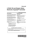
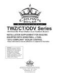
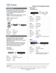
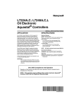
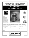
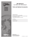
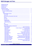
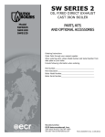
1
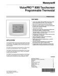
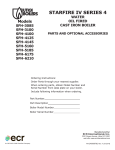
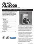
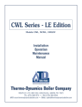
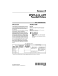
L7224A,C; L7248A,C,L Oil and Electric Boiler Electronic Aquastat® Controllers INSTALLATION INSTRUCTIONS APPLICATION The L7224A,C and L7248A,C,L 2012 Compliant Electronic Aquastat® Controllers provide electronic temperature sensing in a UL limit-rated control with a single sensing probe. The L7224A,C and L7248A,C,L control the circulator, oil or electric burner or contactor, and boiler temperature. The L7224/L7248 is “Outdoor Temperature Reset” ready which is enabled when connected to the W8735Y1000 wireless or W8735S1000 wired Outdoor Reset Kit. Outdoor Reset with the L7224/ L7248 is intended for all applications except for tankless coil systems for domestic hot water. Compliance to 2012 DOE regulation ensures efficiency is maximized without interfering with domestic hot water demand. The L7224A,C and L7248A,C,L replace the L8124A, L8124C, L7124A,C, L7148A and L8148A Controllers. The L7224A,C and L7248A,C,L series controls provide status and diagnostic information through an LED display combined with LED lights as well as EnviraCOM™ communications enabled thermostats and diagnostic tools to enhance the diagnostic process. L7224/L7248 Aquastat Controllers are intended for use in residential-type applications. IMPORTANT Use of Outdoor Temperature Reset on a tankless coil application requiring a Low Limit setting will result in reduced system effectiveness and efficiency. SPECIFICATIONS Electrical Ratings: Voltage: 120 Vac, 60 Hz. Power: 7 VA maximum at 120 Vac plus external loads. Thermostat current: 100 mA nominal at 24 Vac. Burner Relay: 7.4 A at 120 Vac Full Load Amperage (FLA); 44.4 A inrush Locked Rotor Amperage (LRA); Less Ignition Load: 360 VA. Circulator Relay: 7.4 A at 120 Vac FLA; 44.4 A inrush LRA. Zone Controller (ZC): 7.4 A at 120 Vac FLA; 44.4 A inrush LRA. NOTE: All loads combined cannot exceed 2000 VA. Environmental Ratings: Temperature: -30 °F to +150 °F (-34 °C to +66 °C). Humidity: 0 to 95% relative humidity, noncondensing. Approvals: Underwriters Laboratories Inc. Component Recognized. Canadian Underwriters Laboratories Inc. Component Recognized. 2012 DOE Compliance and Operation Operation of this control may delay the burner operation while the residual heat is circulated out of the boiler. NOTE: This operation may be different than earlier electronic Aquastat® revisions which did not implement thermal purge. 68-0281-16 L7224A,C; L7248A,C,L OIL AND ELECTRIC BOILER ELECTRONIC AQUASTAT® CONTROLLERS INSTALLATION Accessories: W8735Y1000 Wireless Outdoor Reset Kit W8735ER1000 Wireless Outdoor Reset Module C7089R1013 Wireless Outdoor Temperature Sensor (requires W8735ER1000) W8735S1000 AquaReset™ Outdoor Reset Kit (includes 50022037-002 Outdoor Reset Module and C7089U1006 Outdoor Temperature Sensor) W8735S1008 AquaReset™ Domestic Hot Water Kit (includes 50022037-005 Domestic Hot Water Module and 32003971-003 Sensor) W8735S3000 EnviraCOM™ Alarm Module C7089U1006 Outdoor Temperature Sensor (used with the 50022037-002) 32003971-003 Temperature Sensor (used with 50022037-005) Sensor (See Table 2). 120650 Heat Conductive Compound. 121371AA Sensor Well Clamp. When Installing this Product... 1. Read these instructions carefully. Failure to follow them could damage the product or cause a hazardous condition. 2. Check the ratings given in the instructions and on the product to make sure the product is suitable for your application. 3. The installer must be a trained, experienced service technician. 4. After installation is complete, check out product operation as provided in these instructions. 5. Set High Limit, Low Limit and Low Limit Differential to the settings recommended by the boiler OEM. 6. Record the maximum High Limit setting from the replaced controller in the text box provided on the cover insert label. 7. Record the High Limit setting at time of installation in the text box provided on the cover insert label. Table 1. Wells for L7224A,C; L7248A,C,L Controllers. Part Number Spud Size in. (mm) 123869A 1/2 (12.7) NPT Insertion in. (mm) Insulation in. (mm) 3 (76.2) 1-1/2 (38.1) 123870A 3/4 (19.05) NPT 3 (76.2) 1-1/2 (38.1) WARNING Electrical Shock Hazard. Can cause severe injury, death or property damage. Disconnect power supply before beginning installation to prevent electrical shock or equipment damage. Table 2. Sensors for L7224A,C and L7248A,C,L Controllers. Part Number 50001464-001 Length in. (mm) Application 12 (304.8) Well-mounted controls 50001464-003 24 (609.6) Flush-mounted controls 50001464-004 36 (914.4) 50001464-005 48 (1219.2) Mounting The L7224A,C and L7248A,C,L models are available in a well-mount, horizontal position, vertical position, or flush mounted remote from the well versions. Dimensions for the variety of mounting options are shown in Fig. 1. Note that each identity will have only a single mounting option. 3/4 (75) 7-1/8 (181) 6-1/2 (166) 5-11/16 (145) 3-1/32 (77) 3/8 (10) 1-3/16 (30) 1-1/8 (29) 1/16 (2) 2-5/8 (67) 4-1/4 (109) 3-13/32 (86) 2x 1/4 (7) x 3/8 (9) Fig. 1. L7224A,C; L7248A,C,L mounting dimensions in inches (mm). IMPORTANT Immersion well must fit sensing element and sensor must rest against bottom of well. 68-0281—16 2-1/16 (53) 2 M22147B L7224A,C; L7248A,C,L OIL AND ELECTRIC BOILER ELECTRONIC AQUASTAT® CONTROLLERS New Installation SENSOR WIRES Order well assemblies separately; see Table 1 and form no. 68-0040, Immersion Wells and Compression Fittings for Temperature Controllers. Boilers usually have tappings that allow the well to be mounted horizontally so boiler water of average temperature can circulate freely over the well. 1. Turn off all power and drain the boiler, if applicable. 2. If no tapping is provided, prepare properly sized and threaded tapping near the top of the boiler. 3. Sparingly coat the well threads with pipe dope. CONTROLLER CASE BOILER IMMERSION WELL HEAT-CONDUCTIVE COMPOUND (OPTIONAL) NOTE: Do not attempt to tighten by using the case as a handle. Turn off all power and remove the old control. Refer to the cover insert of the old control to identify and tag each external lead as it is disconnected. If the old well is unsuitable for the new installation, remove it and replace it with a suitable new well. If the old well is suitable, use it. Well-Mounted Aquastat Replacement Turn off all power and remove the old control. Refer to the cover insert of the old control to identify and tag each external lead as it is disconnected. If the old well is unsuitable for the new installation, remove it and proceed with instructions for new installation. If the old well is suitable, use it. 1. Loosen, but do not remove, the well clamp screw on the side of the control case. 2. Position immersion well clamp snugly over the flange of the adapter and tighten the clamp screw. 3. Insert the sensor into the well as shown in Fig. 2 or 3. (See Replacement Sensor Installation section for details.) IMPORTANT Best thermal response is obtained with a well that snugly fits the sensor. Insert the sensor until it rests against the bottom of the well. Use a well of correct length and bend the wiring, if necessary, to hold the bulb against the bottom of the well. If the well is not a snug fit on the sensor, use the heat-conductive compound (furnished with TRADELINE® models) as follows: Fold the plastic bag of compound lengthwise and twist it gently. Then snip off end of bag and work the open end of the bag all the way into the well. Slowly pull out the bag while squeezing it firmly to distribute compound evenly in the well. Bend the wiring, if necessary, to hold the sensor against the bottom of the well and to hold outer end of the sensor in firm contact with the side of the well. See Fig. 2. Wipe excess compound from the outer end of the well. T THERMOSTAT TERMINALS DISPLAY FUSE SENSOR CONNECTOR SENSOR HOLES B1 ZC B2 C1 L2 ZR LINE ENVIRACOMTM TERMINALS C2 12. Flush-Mounted Aquastat Replacement L1 10. 11. Fig. 2. Position of sensor in immersion well. 1 8. 9. M16120 IMMERSION WELL CLAMP SCREW 2 5. 6. 7. IMMERSION WELL CLAMP Install the well in the boiler tapping and tighten securely. Refill boiler and check for water leakage. Loosen but do not remove the well clamp screw. Fit the case into the well so the clamp on the case slides over the flange on the well. Securely tighten the clamp screw. Insert the sensor element into the well until it bottoms. See Replacement Sensor Installation section for details. (If necessary, slightly bend the wire inside the case to hold the sensor against the bottom of the well.) Turn power ON. Set High Limit, Low Limit and Low Limit Differential to the settings recommended by the boiler OEM. (See OPERATION section.) (See INSTALLATION steps 6 and 7.) On L7248L models, adjust ELL option to match your configuration (see OPERATION section, and Fig. 11 and 13). T 3 4. SENSOR M32186 Fig. 3. Circuit board, showing sensor connection and well holes for horizontal mount models. 3 68-0281—16 L7224A,C; L7248A,C,L OIL AND ELECTRIC BOILER ELECTRONIC AQUASTAT® CONTROLLERS WIRING SENSOR WIRES WARNING BOILER Electrical Shock Hazard. Can cause serious injury or death. Disconnect power supply before making wiring connections to prevent electrical shock or equipment damage. SENSOR All wiring must comply with local electrical codes and ordinances. Do not exceed the specifications in the Application section when wiring this control. Use wire rated for 194 °F (90 °C) or higher. HEAT-CONDUCTIVE COMPOUND (OPTIONAL) M22026 Fig. 4. Replacement sensor installation. IMPORTANT The terminals on these Aquastat Controllers are approved for use with copper wire only. Replacement Sensor Installation Follow the appropriate wiring diagrams shown on the inside of the front cover of the L7224A,C; L7248A,C,L or in Fig. 8–13. Turn off all power and: 1. Carefully disconnect sensor from circuit board by pulling gently on the connector. 2. Gently pull sensor from thermo well and through circuit board by pulling on leadwires. 3. Carefully align replacement sensor with hole in circuit board and guide through Aquastat case and into well. (See Fig. 5). 4. Make sure sensor is fully seated to bottom of well (See Fig. 4). Use a small pencil to measure depth of sensor in well, if necessary. 5. Connect sensor to circuit board by pressing connector on sensor unit into mating connector on circuit board (See Fig. 5). 6. For remote sensors (flush-mounted Aquastat Controllers) be sure to use 121571AA Clamp (see Accessories) to securely hold sensor in place. THERMOSTAT TERMINALS Refer to Fig. 6 for Connections for the optional Outdoor Reset Module and the Domestic Hot Water (DHW) module. In subsequent wiring diagrams these modules will be displayed with a dotted line signifying that they are optional. W8735Y1000 OR W8735S1000 OUTDOOR RESET MODULE (W8735S1000 SHOWN) 1 2 3 OT OT T T 3 2 1 ENVIRACOMTM TERMINALS ZR LINE IMMERSION WELL W8735S1008 DOMESTIC HOT WATER MODULE L1 T L2 T 3 C2 2 1 C7089U1006 OUTDOOR SENSOR B2 DISPLAY 1 2 3 TS TS C1 B1 32003971-003 TEMPERATURE SENSOR ZC LINE ZR L1 M34961 L2 SENSOR CONNECTOR C2 RELAYS Fig. 6. Wiring the Outdoor Reset Module and the Domestic Hot Water Module. B2 C1 B1 OPERATION SENSOR HOLES FUSE General ZC M32187 The L7224A,C and L7248A,C,L Oil Electronic Aquastat Controllers are primary safety limit-rated devices designed for use with oil fired boilers with line voltage burners and circulators. Many boilers do not include wiring or control compartments as part of the design, but are provided with an integral, replaceable, immersion well that is the mounting hardware for the Aquastat Controllers. Wiring to the other controls is done through flexible metal conduit. Fig. 5. Circuit board, showing sensor connection and well holes for vertical mount models. Fuse The 1 Amp fuse located near the transformer is intended to protect the EnviraCOM circuit from incorrect wiring. The Aquastat will continue to function should the fuse blow or be removed though no EnviraCOM communication will be possible on the bus and Err 6 will be displayed. See Table 10. 68-0281—16 For boilers that do include a remotely (flush) mounted control, the wiring may be completed with conduit or routed behind the boiler sheet metal. 4 L7224A,C; L7248A,C,L OIL AND ELECTRIC BOILER ELECTRONIC AQUASTAT® CONTROLLERS A separate electromechanical high-limit is not required in a system that uses this control to meet Underwriters Laboratories Inc. requirements for oil-fired boiler assemblies, UL 726. Table 3. Adjustable Features. Display On the L7224 models, the High Limit, Low Limit, Low Limit Differential, and Anti Short-Cycle time can be adjusted to the setting recommended by the boiler OEM. On the L7248 models, the High Limit, and Anti Short-Cycle time are also adjustable, see “Adjusting Settings”. The overall range of the High Limit is from 130 °F to 240 °F (54 °C to 116 °C). Select devices may have different ranges. Some models have limited ranges on the High Limit setpoint; this limited range is listed on the device label. Some models also have a Low Limit and Low Limit Differential adjustment. The range of the Low Limit is from 110 °F to 220 °F (43 °C to 104 °C). Select devices may have different ranges. The Zr setting can be set to DHW, Zoning, or for tankless coil applications depending on the L7224/L7248. If an Outdoor Reset Module is installed, the reset curve can be set by entering the minimum outdoor temperature, minimum (boiler) temperature, and maximum outdoor temperature on the 3-digit display. The range of the minimum outdoor temperature is from -40 °F to 40 °F (40 °C to 4.4 °C) and has a default setting of 0 °F (-18 °C). The range of the maximum outdoor temperature is from 30 °F to 70 °F (-1.1 °C to 21.1 °C) and has a default setting of 40 °F. The range of the minimum (water or boiler) temperature is from 80 °F to 180 °F (26.7 °C to 82.2 °C) and has a default setting of 130 °F. See the “Outdoor Reset Module” Installation Instructions (form number 69-2335) for more information on setting the boiler reset curve and all related parameters. Definition HL_ High Limit. Hdf High Limit Differential. LL_ Low Limit. (L7224A, C) Ldf Low Limit Differential (L7224A, C) ELL External Low Limit (L7248L only) duu ZR input configured as external Domestic Hot Water (DHW) request (ON/OFF) (L7224A,C/ L7248L) ASC Anti Short-Cycle Timeout (seconds); “OFF” is disabled. otL* Outdoor Temperature Low (minimum) parameter for the outdoor reset curve (°F or °C) otH* Outdoor Temperature High (maximum) parameter for outdoor reset curve (°F or °C) btL* Boiler Temperature Low (minimum) parameter for outdoor reset curve bP* Boost Period (minutes). “OFF” is displayed if Boost is inactive bS* Boost step (°F or °C) shown only if Boost is active (bP=ON) UUS* Warm Weather Shutdown Temperature (°F or °C) tPL** Thermal Purging Limit Temperature (°F or °C), “OFF” if disabled tPt** Termal Purging Time Delay (minutes), shown only if tPL is enabled PC Pump Cycling (ON / OFF) F-C Temperature units (°F or °C) * Settings available for adjustment on the 3-digit display only if a W8735Y1000 or W8735S1000 Outdoor Reset Kit is installed. **Settings available for adjustment only when the W8735Y1000 or W8735S1000 Outdoor Reset Kit is NOT installed. The L7224A,C and L7248A,C,L are designed for use with 24 Vac electronic and electromechanical thermostats or EnviraCOM™ enabled thermostats, and have screw-type terminals for easy field connection. Adjusting Settings Then press the UP and/or DOWN buttons to move the set point to the desired value, to change between °F and °C, or to enable (On) or disable (Off) the External Low Limit. After 60 seconds without any button inputs, the control will automatically return to the RUN mode. To discourage unauthorized changing of Aquastat settings, a procedure to enter the ADJUSTMENT mode is required. To enter the ADJUSTMENT mode, press the UP, DOWN, and I buttons (Refer to Fig. 5) simultaneously for three seconds. Press the I button until the feature requiring adjustment is displayed: Display In the RUN mode, the Aquastat will flash “bt” (boiler temp) followed by the temperature (i.e., 220), followed by °F or °C. To read boiler settings, press the I key to read the parameter of interest. For example, press I and High Limit (HL) is displayed, followed by a three-digit number, i.e., 220, followed by °F or °C. Pressing the I button again (on L7224 models) will display the Low Limit (LL) followed by a three-digit number and the corresponding degree designator. See Display Readout, Table 4. After approximately 60 seconds without any key presses, the display will enter a dim display mode. To return to the bright display mode, simply press any key. 5 68-0281—16 L7224A,C; L7248A,C,L OIL AND ELECTRIC BOILER ELECTRONIC AQUASTAT® CONTROLLERS has not gone below the Low Limit setting (minus the Differential); or, ZR input is not powered with 120 Vac (only L7248L with ELL set On). 2. High Limit: Boiler temperature went above the High Limit setting and has not dropped below the High Limit setting (minus the Differential). 3. Low Limit: Boiler temperature went below the Low Limit setting (minus the Low Limit Differential) and has not gone above the Low Limit setting; or, ZR input is powered with 120 Vac (only L7248L with ELL set On). 4. Error: The controller has detected an error condition (e.g., open sensor) and has shut down the burner output. The ZC output is energized. The controller continues to monitor the system and automatically restarts if the error condition clears. Refer toTable 4. Table 4. Display readout definitions. Text Err bT HL HdF LL Ldf tt ttE brn Cir ZC Zr ELL duu Description Display Boiler Temperature High Limit 1 High Limit Differential Low Limit (L7224 only) Low Limit Differential (L7224 only) Local Thermostat Status EnviraCOM Thermostat Status B1 (Burner) output (ON or OFF) C1 (Circulator) output (ON or OFF) ZC (Zone Control) output (ON or OFF) ZR (Zone Request) Call for HEAT (ON or OFF) External Low Limit Enabled (L7248L only) ZR Configured as Domestic Hot Water Request (L7224, L7248L only) Error Code (if one is present) ASC Anti Short-Cycle Timeout bSP Boiler Set-Point 2 dhc DHW Module Connected 3 (YES or NO) ot Outdoor Temperature 2 otL Outdoor Temperature Low 2 otH Outdoor Temperature High 2 btL Boiler Temperature Low 2 bP Boost Period bS Boost Step 2 UUS 2 Warm Weather Shutdown Temperature 2 The operating sequence for the L7224/L7248 is shown in Table 6–9. High Limit Controller The High Limit opens and turns off the burner when the water temperature reaches the setpoint. The High Limit automatically resets after the water temperature drops past the setpoint and through the Differential. The L7248 models have High Limit Differential presets of 15 °F (8 °C). The L7224 models have High Limit Differential presets of 10 °F (6 °C). Low Limit and Circulator Controller On a temperature rise, with the adjustable Differential at the default setting of 10 °F (6 °C), the burner circuit breaks and the circulator circuit makes (assuming no call for heat is present) at the Low Limit setpoint. On a temperature drop of 10 °F (6 °C) below the Low Limit setpoint, the burner circuit makes and the circulator circuit breaks. See Fig. 7. HIGH LIMIT SETTING LOW LIMIT SETTING 1 Display shows local setting; not the setting as modified by an external enviracom control. 2 Settings are viewable only if the outdoor reset module and outdoor temperature sensor are installed and functioning properly. 3 Settings are viewable only if the domestic hot water module and sensor are installed and functioning properly. 10ºF (6ºC) DIFFERENCE SWITCH MAKES ON TEMPERATURE FALL. BURNER OPERATES ON A CALL FOR HEAT. WITH NO HEATING DEMAND, SWITCH BREAKS ON TEMPERATURE RISE. 1 SWITCH MAKES ON TEMPERATURE FALL, BURNER IS ON TO MAINTAIN MINIMUM WATER TEMPERATURE. CIRCULATOR IS OFF. Operation 1 WHEN WATER REACHES LOW LIMIT SETTING, THE BURNER SHUTS OFF OR THE CIRCULATOR PUMP STARTS (WHEN CALLING FOR HEAT). M23364 The L7224 and L7248 models can be in any of four operational states: Normal, High Limit, Low Limit and Error. The controller moves back and forth from High Limit to Normal to Low Limit state as part of normal operation. Only devices having High Limit settings are restricted to the High Limit and Normal states. However, the controller will enter the Error state when there is an abnormal condition. The operating states are: 1. Normal: Boiler temperature went below the High Limit setting (minus the Differential) and has not exceeded the High Limit setting; or, the boiler temperature went above the Low Limit setting and 68-0281—16 L7224: 10°F (6°C) DIFFERENCE L7248: 15°F (8°C) DIFFERENCE SWITCH BREAKS ON TEMPERATURE RISE. BURNER TURNS OFF. CIRCULATOR OPERATES ON A CALL FOR HEAT. Fig. 7. Setpoints and differentials. Anti Short-Cycle Feature The Anti Short-Cycle feature allows for field selection of a delay time between burner cycles. Should a call for heat occur following the end of the previous heat cycle and before the Anti Short-Cycle delay time is expired, the circulator will be allowed to run, but the burner will be held off until the time has elapsed. The range of the Anti ShortCycle time is from OFF to five minutes. 6 L7224A,C; L7248A,C,L OIL AND ELECTRIC BOILER ELECTRONIC AQUASTAT® CONTROLLERS NOTE: This feature is blocked if a Domestic Hot Water demand occurs. Domestic Hot Water demands are serviced immediately, without any delay. When the Boiler temperature reaches the Frost Protection Limit temperature plus a fixed 10 °F differential, the burner is turned off unless requested to stay on due to a different demand. NOTE: When the Aquastat is connected to the oil primary and/or thermostat via the EnviraCOM bus, the Anti Short-Cycle time does not apply to recycle events such as loss of airflow or flame. It applies only to loss of demand. Thermal Purge Operation The intent of thermal purge is to insure usable residual heat in the boiler is circulated until it is sufficiently depleted from the system before the burner is allowed to fire. To that end, on a call for heat, the burner is held off while the circulator runs until the boiler temperature drops to the thermal purge temperature or a time delay is exceeded. Both of these parameters are adjustable. When the boiler temperature reaches the thermal purge temperature, the burner is allowed to fire. Thermal purge is only applied to cold start Aquastat models (L7248) and will not interfere with domestic hot water call for heat or boilers equipped with Honeywell outdoor reset accessories. For warm start models where a Low Limit must be set, thermal purge is not applied. ZR-Domestic Hot Water (DHW) Request The ZR terminal can be selected to service an indirect water heater heat request. This parameter is set via the 3 digit display (see Adjusting Settings section of this document). A heat request via the ZR terminal will have priority over all other features such as the Anti ShortCycle feature or those enabled by the Outdoor Reset Module (See form #69-2335 for more information). In addition to the thermal purge temperature and thermal purge time delay parameters, two other conditions release the Aquastat from thermal purge in order to maintain comfort in the space: • The boiler temperature has dropped 10 °F from the beginning of the thermal purge. • Boiler temperature is cooling at a rate greater than 5 °F/minute while the circulator is running. The thermal purge feature applies to single zone as well as multi-zone applications. Frost Protection The Frost Protection function protects the boiler and potentially the boiler plumbing from possible damage which may occur should the water in the system begin to freeze. The Frost Protection feature is enabled only in the L7248 (cold start models). The feature default setting is enabled (ON), but can be disabled using the 3-digit display. See “Adjusting Settings” on page 5. When the Boiler temperature drops to the Frost Protection Limit temperature (fixed 40 °F), the burner is forced on. The Circulator and ZC outputs remain in the same state as before the Frost Protection function was enabled. They can be either ON or OFF during the Frost Protection cycle. Thermal Purge Settings Some thermal purge parameters are configurable using the 3 digit display. See “Adjusting Settings” on page 5. Thermal purge may be disabled by setting the thermal purge temperature limit to "OFF". Table 5. Thermal Purge Settings. Parameter name Boiler temperature drop Thermal purge temperature limit Thermal purge temperature rate of drop Thermal purge time delay Minimum value Maximum Value Default Not adjustable Not adjustable 10 °F 120 °F (or OFF) 160 °F 140 °F (L7248) Not adjustable Not adjustable 5 °F/minute 1 minute 10 minutes 2 minutes CHECKOUT Thermal Purge and Domestic Hot Water Put the system into operation and observe at least one complete cycle to make sure that the controller operates properly. See TROUBLESHOOTING section to use LED to assist in determining system operation. The thermal purge feature is automatically disabled whenever there is a call for domestic hot water either from the Zr terminal or from the DHW Module to insure hot water is available in a timely manner. See “ZR-Domestic Hot Water (DHW) Request” on page 7. TROUBLESHOOTING Pump Cycling When attempting to diagnose system performance, reference to the LED display can help to identify specific areas not working properly. The LED display will scroll Err, followed by a digit (1-8). Refer to Table 10 and 11 for a description of each error and suggested actions. The Pump Cycling feature exercises the system pump for 15 seconds after a non-adjustable five day period of no boiler activity. The Pump Cycling feature default setting is enabled (ON) but can be disabled (OFF) using the 3-digit display. See “Adjusting Settings” on page 5. 7 68-0281—16 L7224A,C; L7248A,C,L OIL AND ELECTRIC BOILER ELECTRONIC AQUASTAT® CONTROLLERS LINE VOLTAGE INDIRECT TANK AQUASTAT L1 (HOT) W8735Y1000 OR W8735S1000 1 2 3 OT OT L1 (HOT) 1 INDIRECT TANK CIRCULATOR L2 L2 C7089U OUTDOOR SENSOR 2 T T 3 2 1 ZR LINE SENSOR L1 LINE VOLTAGE CIRCULATOR L2 C2 B2 LINE VOLTAGE OIL BURNER RELAY C1 B1 ZC 1 OUTDOOR RESET MODULE IS OPTIONAL. W8735S1000 WIRED OUTDOOR RESET MODULE SHOWN. 2 FOR BEST PERFORMANCE SET DUU=”ON”. M32023A Fig. 8. L7224A,C; L7248L single heat zone with indirect water tank and circulators. Optional Outdoor Reset Module. 68-0281—16 8 L7224A,C; L7248A,C,L OIL AND ELECTRIC BOILER ELECTRONIC AQUASTAT® CONTROLLERS Table 6. L7224/L7248 Controller Operating Sequence. Action System Response Thermostat calls for heat. Circulator starts when water temperature is above Low Limit setting (if applicable) or above the Thermal Purge Temperature Limit (tPL) if Thermal Purge is enabled. Boiler temperature is checked. Burner starts when water temperature is below High Limit setting minus the differential or at or below the Thermal Purge Temperature Limit (tPL) for cold start boilers if the Thermal Purge Temperature Limit is enabled. If tPL is enabled, the burner may also start if the boiler temperature is cooling at 10 ºF or greater per minute or the Thermal Purge Time Delay (tPt) has expired. If Anti Short-Cycle Time is enabled, the burner does not start until the set Anti Short-Cycle Time between cycles expires after the previous call for heat was satisfied. Boiler temperature exceeds the High Limit. Burner is turned off. Burner restarts when the water temperature drops below the High Limit setting minus the Differential. If Thermal Purge is enabled, the burner is turned on when either the Thermal Purge Temperature Limit is reached, the Thermal Purge Time Delay has expired or the boiler temperature cooling rate exceeds 10 ºF/ minute. Thermostat is satisfied. Circulator and burner turn off. Boiler temperature drops below the Low Limit Burner is turned on, Circulator is turned off. Burner stops when the setting minus the differential (if applicable). water temperature exceeds the Low Limit setting. Power to Zc is removed. Error condition 1-5. If an error condition is detected, all outputs except ZC are shut down. Burner is off. Control continues to function and restarts when error is corrected. During the error check sequence, the system checks for drift in the sensor and corrosion in the connections. Error condition 6. EnviraCOM communication is not available. Error condition 7. The control has reset the High Limit, Low Limit and Differential setting to a default setting and will continue to run at those settings. Performance of the system will be degraded. Error condition 8. If the error condition is detected, all outputs except ZC are shut down. Burner is off. Control continues to function and restarts when all three user keys have been pressed longer than 60 seconds. Error condition 9*. System continues to run with no outdoor reset functionality Error condition 10*. System continues to run with outdoor reset parameters enabled as programmed. Error cleared automatically. Error condition 11*. System continues to run with boiler temp set to High Limit. * Error condition only available when the Outdoor Reset Module is installed. Table 7. L7224/L7248 Controller Operating Sequence with multiple zones connected through the ZR terminal. Action System Response Zone Request (ZR) terminal is connected to L1 (Zone calls for heat). Boiler temperature is checked. Burner starts when water temperature is below High Limit setting or at or below the Thermal Purge Temperature Limit (tPL) for cold start boilers if the Thermal Purge Temperature Limit is enabled. If tPL is enabled, the burner may also start if the boiler temperature is cooling at 10 ºF or greater per minute or the Thermal Purge Time Delay (tPt) has expired. Anti Short-Cycle Time is applied, see Table 6. Boiler temperature exceeds the High Limit. Burner is turned off. Burner restarts when the water temperature drops below the High Limit setting minus the Differential. If Thermal Purge is enabled, the burner is turned on when either the Thermal Purge Temperature Limit is reached, the Thermal Purge Time Delay has expired or the boiler temperature cooling rate exceeds 10 ºF/ minute. Zone Request input is de-energized (Zones are satisfied). Burner turns off. Boiler temperature drops below the Low Limit Burner turns on and Zone Control is de-energized. Burner turns off setting minus the differential (if applicable). and Zone Control is re-energized when the water temperature exceeds the Low Limit setting. 9 68-0281—16 L7224A,C; L7248A,C,L OIL AND ELECTRIC BOILER ELECTRONIC AQUASTAT® CONTROLLERS . Table 8. Controller Operating Sequence with External Low Limit device connected trough the ZR terminal. Action System Response Zone Request (ZR) terminal is connected to L1 (External Low Limit call for heat). Boiler temperature is checked. Burner starts when water temperature is below High Limit setting. Circulator turns off. Boiler temperature exceeds the High Limit. Burner is turned off. Burner restarts when the water temperature drops below the High Limit setting minus the Differential. Zone Request input is de-energized (External Burner is turned off. Low Limit is satisfied). Table 9. L7224 Controller Operating Sequence with Domestic Hot Water connected trough the ZR terminal. Action System Response Zone Request (ZR) terminal is connected to L1 (Domestic Hot Water calls for heat). Boiler temperature is checked. Burner starts when water temperature is below High Limit setting. Boiler temperature exceeds the High Limit. Burner is turned off. Burner restarts when the water temperature drops below the High Limit setting minus the Differential. Zone Request input is de-energized (Domestic Hot Water is satisfied). Burner is turned off. Table 10. LED Error Codes. Aquastat Error Code EnviraCOM Alarm Cause/Action Err1 Aquastat sensor fault; check water sensor. 18 Err2 ECOM fault; check EnviraCOM™ wiring. 18 Err3 Excessive electrical noise or frequency out of range. Hardware fault; replace controller. 18, 58 Err4 B1 fault; check B1 wiring/voltage. 64 Err5 Low Line; check L1-L2, 110 Vac. 59 Err6a Warning: Fuse; check ECOM wires, replace fuse. 92 Err7 Warning: EEPROM, HL, LL, Hdf, Ldf; reset to default values. N/A Err 8b Repeated B1 fault (voltage present at B1 when output is turned off); check B1 wiring/voltage. 25 Err9a Warning: Outdoor Reset System failure; communication to Outdoor Reset Module lost, 50, 53, 149 Outdoor Reset Module failure, multiple outdoor temperature sensors detected on the bus, or outdoor temperature sensor failure. Check EnviraCOM wiring (1, 2, 3), check sensor wiring. Err 10a Warning: Boost Failure; Boost Mode active at least once per cycle for the last 60 consecutive 150 cycles. Check Outdoor Reset curve settings. Err 11a DHW Module/Sensor failure; communication to DHW Module lost, DHW Module failure, or temperature sensor failure. Check EnviraCOM wiring (1, 2, 3), check sensor wiring. 146, 147, 148 a Warnings are generated to enunciate the system is not operating optimally, but the Aquastat is still operating and maintaining boiler temperature. In the instance where an Outdoor Reset Module is used, the warnings may indicate a reset curve setting error one or more features is not running optimally, and the Aquastat is reverting to default settings or has stopped running the Outdoor Reset algorithms. The warnings are cleared when the issue(s) is resolved. b To clear Err 8 condition, depress and hold all three user keys simultaneously for 60 seconds. Err 8 condition clears and display returns to normal. Err 8 condition is designed to catch welded relays on the Aquastat and will normally only occur near end of life for the control. If Err 8 condition has occurred early in the controls life, be sure to check for voltage feedback to B1 when B1 should be off and check current draw on b terminal to be sure oil burner is not drawing excessive current. Err 8 condition will keep repeating if B1 fault is not cleared. Table 11. Troubleshooting Guide System Condition Diagnostic Condition Boiler is cold, Display is OFF. house is cold. Display is ON. 68-0281—16 Check Action 120 Vac System power. Turn system power on. 24 Vac T-T No 24 V; replace control. 24 V present; disconnect thermostat, short T-T. Boiler starts, check wiring and thermostat. 120 Vac at B1-B2 • If no, replace control. • If yes, check burner and wiring. Refer to Err on display. — 10 L7224A,C; L7248A,C,L OIL AND ELECTRIC BOILER ELECTRONIC AQUASTAT® CONTROLLERS Table 11. Troubleshooting Guide System Condition Diagnostic Condition Check Boiler is hot, Display is ON. house is cold. Action 120 Vac at C1-C2 • • • • Boiler below the Low Limit temperature, wait for boiler to go above Low Limit temperature. — 120 Vac at C1-C2, check wiring to pump. Wiring OK, is pump running? If not, replace the pump. If pump is running, check for trapped air or closed zone valves. Boiler above LL? If yes, check for • If no 120 Vac, replace control. 120 Vac between ZC and L2. • If yes, check zone relays, circulators and wiring. • Set ELL to Off for multizone system (see Fig. 11). • Set ELL to On for External Low Limit (see Fig. 13). ELL setting (L7248L only) Boiler above LL? If yes, check 120 • If no 120 Vac, check C1-C2 (see above). Vac at ZR-L2 (only L7248L with • If yes, check the External Low Limit control. ELL set On) Boiler is hot, Display is ON. no hot potable water. Boiler Demand signal from the water heater (either 120 Vac at ZR-L2, or 0 Vac on T-T; depends on installation and “duu” setting) • 24 Vac on T-T (or 0 Vac on ZR-L2), check wiring to water heater • Wiring OK, check the water heater “duu” setting • Set duu to ON if 120 Vac water heater demand is connected to ZR • Set duu to OFF if open/closed water heater demand is connected to T-T Check DHW Module and DHW Sensor • DHW Module not properly connected and/or DHW Sensor improperly positioned TO ADDITIONAL R845A RELAYS FOR OTHER ZONES ZONE 2 CIRCULATOR 1 L1 L2 (HOT) LOW VOLTAGE THERMOSTAT 2 L7224 R845A RELAY ZONE 2 T 6 T 3 5 2 1 3 4 ZR 1 LINE VOLTAGE CIRCULATOR 2 ZONE 2 LOW VOLTAGE THERMOSTAT 1 2 POWER SUPPLY. PROVIDE DISCONNECT MEANS AND OVERLOAD PROTECTION AS REQUIRED. LINE SENSOR L1 L2 C2 B2 LINE VOLTAGE OIL BURNER RELAY C1 B1 ZC CONTROL CASE MUST BE CONNECTED TO EARTH GROUND. USE GROUNDING SCREW PROVIDED. M27115 Fig. 9. L7224A,C multizone system with circulator connections. 11 68-0281—16 L7224A,C; L7248A,C,L OIL AND ELECTRIC BOILER ELECTRONIC AQUASTAT® CONTROLLERS 2 3 LINE VOLTAGE INDIRECT TANK AQUASTAT W8735Y1000 OR W8735S1000 1 1 2 3 OT OT 6 TH9421C R7184/R7284 T LIMIT T3 L1 2 L2 1 C7089U1006 OUTDOOR SENSOR INDIRECT TANK CIRCULATOR L2 L1 3 2 1 (HOT) L2 L7224 T T 3 1 2 ENVIRACOM™ TERMINAL BURNER MOTOR IGNITER VALVE 3 1 BURNER MOTOR 3 SENSOR 7 IGNITER 3 L1 LINE VOLTAGE CIRCULATOR VALVE L2 C2 4 TO REMOTE ALARM CIRCUIT 2 CAD CELL ZR LINE 5 B2 CAD CELL C1 B1 JUNCTION BOX LEGEND SCREW TERMINAL ZC 1/4 IN. (6 MM) QUICK CONNECT TERMINAL SOLDERLESS WIRE CONNECTION 1 POWER SUPPLY. PROVIDE DISCONNECT MEANS AND OVERLOAD PROTECTION AS REQUIRED. 2 OPTIONAL FEATURE ON SELECT MODELS. 3 REFER TO DEVICE LABEL FOR WIRE COLOR CODE. 4 VALVE IS OPTIONAL ON SPECIFIED MODELS. 5 ENVIRACOM™ TERMINAL 3 IS ALSO THE FIRST THERMOSTAT TERMINAL. 6 OPTIONAL OUTDOOR RESET MODULE AND OUTDOOR SENSOR. W8735S1000 WIRED OUTDOOR RESET MODULE SHOWN. 7 DUU MUST BE SET TO “ON” ON THE AQUASTAT. M32025B Fig. 10. L7224A,C single zone system with circulator and indirect water tank with EnviraCOM™ thermostat. 68-0281—16 12 L7224A,C; L7248A,C,L OIL AND ELECTRIC BOILER ELECTRONIC AQUASTAT® CONTROLLERS ELL=OFF TO ADDITIONAL R845A RELAYS FOR OTHER ZONES ZONE 2 CIRCULATOR L1 1 (HOT) L2 R845A RELAY ZONE 2 6 5 3 4 1 2 ZONE 2 LOW VOLTAGE THERMOSTAT LOW VOLTAGE THERMOSTAT 2 L7248L T ENVIRACOM 4 TERMINALS W8735Y1000 OR W8735S1000 1 2 3 OT OT T 3 3 2 1 ZR LINE VOLTAGE CIRCULATOR LINE SENSOR C7089U1006 OUTDOOR SENSOR W8735S1008 DOMESTIC HOT 5 WATER MODULE L1 L2 C2 1 2 3 TS TS B2 LINE VOLTAGE OIL BURNER RELAY C1 32003971-003 TEMPERATURE SENSOR B1 ZC 1 POWER SUPPLY. PROVIDE DISCONNECT MEANS AND OVERLOAD PROTECTION AS REQUIRED. 2 CONTROL CASE MUST BE CONNECTED TO EARTH GROUND. USE GROUNDING SCREW PROVIDED. 3 OPTIONAL OUTDOOR RESET MODULE AND OUTDOOR SENSOR. W8735S1000 WIRED OUTDOOR RESET MODULE SHOWN. 4 ENVIRACOM TERMINALS. 5 OPTIONAL DOMESTIC HOT WATER MODULE AND TEMPERATURE SENSOR. M29655A Fig. 11. L7248L multizone system with circulator connections. 13 68-0281—16 L7224A,C; L7248A,C,L OIL AND ELECTRIC BOILER ELECTRONIC AQUASTAT® CONTROLLERS W8735Y1000 OR W8735S1000 W8735S1008 MULTI-ZONE RELAY PANEL 1 2 3 TS TS 1 2 3 OT OT C7089U OUTDOOR SENSOR 6 7 32003971-003 TEMPERATURE SENSOR T T 9 8 R7184/R7284 T LIMIT T3 L1 2 L2 L1 (HOT) L2 1 L7224 T T 3 1 2 ENVIRACOM™ TERMINAL BURNER MOTOR IGNITER VALVE 3 1 BURNER MOTOR 3 SENSOR IGNITER 3 ZR L1 LINE VOLTAGE CIRCULATOR VALVE L2 C2 4 TO REMOTE ALARM 2 CIRCUIT B2 CAD CELL CAD CELL LINE 5 C1 B1 ZC JUNCTION BOX LEGEND SCREW TERMINAL 1/4 IN. (6 MM) QUICK CONNECT TERMINAL SOLDERLESS WIRE CONNECTION 1 POWER SUPPLY. PROVIDE DISCONNECT MEANS AND OVERLOAD PROTECTION AS REQUIRED. 6 OPTIONAL OUTDOOR RESET MODULE AND OUTDOOR SENSOR. W8735S1000 WIRED OUTDOOR RESET MODULE SHOWN. 2 OPTIONAL FEATURE ON SELECT MODELS. 7 OPTIONAL DOMESTIC HOT WATER MODULE. 3 REFER TO DEVICE LABEL FOR WIRE COLOR CODE. 8 4 VALVE IS OPTIONAL ON SPECIFIED MODELS. WIRE ONLY THE ENVIRACOM TERMINALS (1, 2, 3) ON OIL PRIMARY IF CONNECTING TO REMOTE DIAGNOSTICS, OTHERWISE CONNECT A JUMPER BETWEEN THE TT TERMINALS. 5 ENVIRACOM™ TERMINAL 3 IS ALSO THE FIRST THERMOSTAT TERMINAL. 9 ZONE PANEL TERMINALS MAY HAVE DIFFERENT LABEL. CHECK PANEL MANUFACTURER SPECIFICATIONS FOR WIRING INSTRUCTIONS. M32024A Fig. 12. L7224/L7248 multizone system with Outdoor Reset and Domestic Hot Water Modules (indirect tank applications). 68-0281—16 14 L7224A,C; L7248A,C,L OIL AND ELECTRIC BOILER ELECTRONIC AQUASTAT® CONTROLLERS ELL=ON 1 L2 L1 (HOT) R W L6006 LOW LIMIT CONTROLLER B LOW VOLTAGE THERMOSTAT 2 L7248L T T 3 2 1 LINE SENSOR ZR LINE VOLTAGE CIRCULATOR L1 L2 C2 B2 LINE VOLTAGE OIL BURNER RELAY C1 B1 ZC 1 2 POWER SUPPLY. PROVIDE DISCONNECT MEANS AND OVERLOAD PROTECTION AS REQUIRED. CONTROL CASE MUST BE CONNECTED TO EARTH GROUND. USE GROUNDING SCREW PROVIDED. M27113 Fig. 13. L7248L External Low Limit connections. 15 68-0281—16 L7224A,C; L7248A,C,L OIL AND ELECTRIC BOILER ELECTRONIC AQUASTAT® CONTROLLERS Automation and Control Solutions Honeywell International Inc. 1985 Douglas Drive North Golden Valley, MN 55422 customer.honeywell.com ® U.S. Registered Trademark © 2013 Honeywell International Inc. 68-0281—16 M.S. Rev. 09-13 Printed in United States