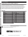
1
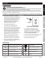
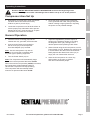
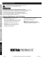
Owner’s Manual & Safety Instructions
Save This Manual Keep this manual for the safety warnings and precautions, assembly, operating,
inspection, maintenance and cleaning procedures. Write the product’s serial number in the back of the manual
near the assembly diagram (or month and year of purchase if product has no number). Keep this manual and
the receipt in a safe and dry place for future reference.
oilless airbrush
compressor
REV 11l
Visit our website at: http://www.harborfreight.com
Email our technical support at: [email protected]
ITEM 93657
When unpacking, make sure that the product is intact
and undamaged. If any parts are missing or broken,
please call 1-800-444-3353 as soon as possible.
Copyright© 2005 by Harbor Freight Tools®. All rights reserved.
No portion of this manual or any artwork contained herein may be reproduced in
any shape or form without the express written consent of Harbor Freight Tools.
Diagrams within this manual may not be drawn proportionally. Due to continuing
improvements, actual product may differ slightly from the product described herein.
Tools required for assembly and service may not be included.
Read this material before using this product.
Failure to do so can result in serious injury.
SAVE THIS MANUAL.
Table of Contents
Safety.......................................................... 2
Maintenance................................................ 8
Setup........................................................... 6
Parts List and Diagram............................... 10
Specifications.............................................. 6
Warranty..................................................... 12
SAFETY
Operation..................................................... 7
SETUP
WARNING SYMBOLS AND DEFINITIONS
This is the safety alert symbol. It is used to alert you to potential personal injury hazards.
Obey all safety messages that follow this symbol to avoid possible injury or death.
Indicates a hazardous situation which, if not avoided,
will result in death or serious injury.
Indicates a hazardous situation which, if not avoided,
could result in death or serious injury.
Indicates a hazardous situation which, if not avoided,
could result in minor or moderate injury.
OPERATION
Addresses practices not related to personal injury.
MAINTENANCE
Page 2
For technical questions, please call 1-800-444-3353.
Item 93657
IMPORTANT SAFETY INFORMATION
WARNING Read all safety warnings and instructions.
Failure to follow the warnings and instructions may result in electric shock, fire and/or serious injury.
Save all warnings and instructions for future reference.
The warnings, precautions, and instructions discussed in this instruction manual cannot cover all possible
conditions and situations that may occur. It must be understood by the operator that common sense
and caution are factors which cannot be built into this product, but must be supplied by the operator.
4. Compressor use and care
c. Keep children and bystanders away
from an operating compressor.
2. Electrical safety
a. Compressor plugs must match the outlet.
Never modify the plug in any way.
Do not use any adapter plugs with grounded
compressors. Standard plugs and matching
outlets will reduce risk of electric shock.
b. Do not expose compressor to rain or wet
conditions. Water entering a compressor
will increase the risk of electric shock.
c. Do not abuse the cord. Never use the
cord for unplugging the compressor.
Keep cord away from heat, oil, sharp edges
or moving parts. Damaged or entangled
cords increase the risk of electric shock.
3. Personal safety
a. Stay alert, watch what you are doing and
use common sense when operating this
compressor. Do not use this compressor
while you are tired or under the influence
of drugs, alcohol or medication. A moment
of inattention while operating a compressor
may result in serious personal injury.
b. Use personal protective equipment.
Always wear ANSI-approved eye
protection during setup and use.
c. Prevent unintentional starting. Ensure the
switch is in the off‑position before connecting
to power source or moving the compressor.
Item 93657
b. Disconnect the plug from the power source
before making any adjustments, changing
accessories, or storing the compressor.
Such preventive safety measures reduce the
risk of starting the compressor accidentally.
c. Store an idle compressor out of the reach
of children and do not allow persons
unfamiliar with the compressor or these
instructions to operate it. A compressor is
dangerous in the hands of untrained users.
d. Maintain the compressor. Keep the
compressor clean for better and safer
performance. Follow instructions for
lubricating and changing accessories.
Keep dry, clean and free from oil and grease.
Check for misalignment or binding of moving
parts, breakage of parts and any other
condition that may affect the compressor’s
operation. If damaged, have the compressor
repaired before use. Many accidents are
caused by a poorly maintained compressor.
e. Use the compressor in accordance with
these instructions, taking into account
the working conditions and the work to
be performed. Use of the compressor for
operations different from those intended
could result in a hazardous situation.
SETUP
b. Do not operate the Compressor in explosive
atmospheres, such as in the presence
of flammable liquids, gases or dust.
Compressor motors produce sparks
which may ignite the dust or fumes.
a. Do not use the compressor if the switch
does not turn it on and off. Any compressor
that cannot be controlled with the switch
is dangerous and must be repaired.
OPERATION
a. Keep work area clean and well lit.
Cluttered or dark areas invite accidents.
5. Service
a. Have your compressor serviced by a
qualified repair person using only identical
replacement parts. This will ensure that the
safety of the compressor is maintained.
For technical questions, please call 1-800-444-3353.
Page 3
MAINTENANCE
1. Work area safety
SAFETY
General Safety Warnings
Air Compressor Safety Warnings
SAFETY
1. Risk of fire or explosion - do not spray flammable
liquid in a confined area or towards a hot surface.
Spray area must be well‑ventilated. Do not
smoke while spraying or spray where spark or
flame is present. Arcing parts - keep compressor
at least 20 feet away from explosive vapors,
such as when spraying with a spray gun.
2. Risk of bursting - do not adjust regulator higher
than marked maximum pressure of attachment.
3. Risk of injury - do not direct air
stream at people or animals.
a. Make sure your extension cord
is in good condition.
b. Be sure to use an extension cord which is heavy
enough to carry the current your product will draw.
An undersized cord will cause a drop in line
voltage resulting in loss of power and overheating.
Table A shows the correct size to use depending
on cord length and nameplate ampere rating.
If in doubt, use the next heavier gauge. The
smaller the gauge number, the heavier the cord.
14. Industrial applications must follow OSHA guidelines.
15. Maintain labels and nameplates on the
compressor. These carry important safety
information. If unreadable or missing, contact
Harbor Freight Tools for a replacement.
4. Do not use to supply breathing air.
5. Do not leave compressor unattended
for an extended period while plugged in.
Unplug compressor after working.
SETUP
16. This product is not a toy.
Keep it out of reach of children.
6. Keep compressor well-ventilated.
Do not cover compressor during use.
17. Operate unit on level surface.
7. Drain Tank daily and after use.
18. People with pacemakers should consult their
physician(s) before use. Electromagnetic fields in
close proximity to heart pacemaker could cause
pacemaker interference or pacemaker failure.
8. Do not remove the valve cover or
adjust internal components.
9. Compressor head gets hot during operation.
Do not touch it or allow children nearby during
or immediately following operation.
10. Do not use the air hose to move the compressor.
OPERATION
11. The use of accessories or attachments not
recommended by the manufacturer may
result in a risk of injury to persons.
12. All air line components, including hoses, pipe,
connectors, filters, etc., must be rated for a minimum
working pressure of 150 PSI, or 150% of the
maximum system pressure, whichever is greater.
19. WARNING: The brass components of
this product contain lead, a chemical
known to the State of California to cause
birth defects (or other reproductive harm).
(California Health & Safety code § 25249.5, et seq.)
20. This Compressor will automatically shut
off on overload or under excessive heat.
Should this occur, turn the Power Switch (34) to
its “OFF” position. Wait until the Compressor
cools. Then, turn the Power Switch to
its “ON” position to resume work.
21. Spray painting only. Never use this unit with
gasoline, kerosene, or any other flammable solvent.
13. USE OF AN EXTENSION CORD IS NOT
RECOMMENDED. If you choose to use an
extension cord, use the following guidelines:
Table A: RECOMMENDED MINIMUM WIRE
GAUGE FOR EXTENSION CORDS
(120 VOLT)
MAINTENANCE
NAMEPLATE
AMPERES
(at full load)
EXTENSION CORD
LENGTH
25′
50′
100′ 150′
0–6
18
16
16
14
6.1 – 10
18
16
Do not use.
10.1 – 12
16
16
Do not use.
12.1 – 16
14
12
Do not use.
SAVE THESE INSTRUCTIONS.
Page 4
For technical questions, please call 1-800-444-3353.
Item 93657
TO PREVENT ELECTRIC SHOCK AND DEATH
FROM INCORRECT GROUNDING WIRE CONNECTION:
Check with a qualified electrician if you are in doubt as to whether the outlet is properly grounded.
Do not modify the power cord plug provided with the compressor.
Never remove the grounding prong from the plug. Do not use the compressor if the power cord or plug is
damaged. If damaged, have it repaired by a service facility before use. If the plug will not fit the outlet, have a
proper outlet installed by a qualified electrician.
SAFETY
Grounding
110-120 V~ Grounded Compressors: Compressors with Three Prong Plugs
2. Do not modify the plug provided –
if it will not fit the outlet, have the proper
outlet installed by a qualified electrician.
3. Improper connection of the equipment-grounding
conductor can result in a risk of electric shock.
The conductor with insulation having an outer
surface that is green with or without yellow
stripes is the equipment-grounding conductor.
If repair or replacement of the electric cord or
plug is necessary, do not connect the equipmentgrounding conductor to a live terminal.
4. Check with a qualified electrician or service
personnel if the grounding instructions are
not completely understood, or if in doubt as to
whether the compressor is properly grounded.
SETUP
6. Repair or replace damaged or worn cord immediately.
Grounding
Pin
125 V~ 3-Prong Plug and Outlet
(for up to 125 V~ and up to 15 A)
7. This compressor is intended for use on a
circuit that has an outlet that looks like the
one illustrated above in 125 V~ 3-Prong Plug
and Outlet. The compressor has a grounding
plug that looks like the plug illustrated above
in 125 V~ 3-Prong Plug and Outlet.
8. The outlet must be properly installed and grounded
in accordance with all codes and ordinances.
9. Do not use an adapter to connect this
compressor to a different outlet.
OPERATION
1. In the event of a malfunction or breakdown,
grounding provides a path of least resistance for
electric current to reduce the risk of electric shock.
This compressor is equipped with an electric
cord having an equipment-grounding conductor
and a grounding plug. The plug must be
plugged into a matching outlet that is properly
installed and grounded in accordance
with all local codes and ordinances.
5. Use only 3-wire extension cords that have
3-prong grounding plugs and 3-pole receptacles
that accept the compressor’s plug.
PSI
Pounds per square inch of pressure
Double Insulated
CFM
Cubic Feet per Minute flow
Canadian Standards Association
SCFM
Cubic Feet per Minute flow
at standard conditions
Underwriters Laboratories, Inc.
NPT
National pipe thread, tapered
NPS
National pipe thread, straight
Item 93657
V~
A
Volts Alternating Current
Amperes
For technical questions, please call 1-800-444-3353.
Page 5
MAINTENANCE
Symbology
Specifications
SAFETY
Electrical Rating
Motor
Power Cord
Thermal Protection
Maximum Air Pressure
/ Automatic Shut Off
Automatic Restart
Air Output
Air Outlet Size
Hose Dimensions
Base Dimensions
120V~ / 60Hz / 2A
1,750 RPM
6′ Long Power Cord (18AWG x 3C)
Automatic shut-off on overload/overheat and automatic reset
58 PSI
43 PSI
.5 CFM @ 20 PSI
1/8″-28 NPS Air Outlet with 1/4″-18 NPT Male Adapter
.236″ OD x .157″ ID x 10′ Long (1/8″-28 NPS Female Adapter - both sides)
7-3/8″ L x 5-3/8″ W x 1″ H
SETUP
Setup - Before use:
Read the ENTIRE IMPORTANT SAFETY INFORMATION section at the beginning of this
manual including all text under subheadings therein before set up or use of this product.
OPERATION
TO PREVENT SERIOUS INJURY
FROM ACCIDENTAL OPERATION:
Turn the Power Switch “OFF” and unplug
the Air Compressor from its electrical
outlet before assembling or making any
adjustments to the compressor.
Note: For additional information regarding the
parts listed in the following pages, refer to the
Assembly Diagram near the end of this manual.
Before operating, make sure the Air Compressor is set
up in a well-ventilated area, on a flat, level, solid surface
well away from any flammable objects, such as drapes.
Never paint in an area without proper ventilation,
or near possible ignition sources.
Handle
(30)
Pressure
Regulator (40)
Power
Switch
(34)
Pressure
Gauge (11)
Water Drain
Valve (41)
Air Hose (43)
Figure A: Functions
MAINTENANCE
Page 6
For technical questions, please call 1-800-444-3353.
Item 93657
Operating Instructions
Compressor Area Set Up
1. Designate a work area that is clean and well‑lit.
The work area must not allow access by
children or pets to prevent injury.
2. Locate the Compressor on a flat level surface to
ensure proper pump lubrication and to prevent
damage to the unit. Keep at least 12″ of space
around the unit to allow air circulation.
3. Route the power cord from the compressor
to the grounded wall outlet, along a safe path
without creating a tripping hazard or exposing
the power cord to possible damage.
SAFETY
Read the ENTIRE IMPORTANT SAFETY INFORMATION section at the beginning of this
manual including all text under subheadings therein before set up or use of this product.
2. Connect an Air Brush (not included) to
the Air Hose (43) of the Compressor.
Use Hose Adapter (44) if needed.
Note: Use this Compressor only with air
brushes; do not use this compressor with
any other type of painting equipment.
3. Turn the Power Switch (34) on.
5. When finished using the Air Compressor, turn its
Power Switch (34) off. Release any remaining air
in a safe fashion and disconnect the Air Brush.
Briefly depress the Water Drain Valve (41) to
empty the unit of water after each use.
6. Store the Air Compressor in a clean, dry,
safe location out of reach of children
and other unauthorized people.
MAINTENANCE
Note: The Compressor will automatically begin
to run when the air pressure falls below 43 PSI.
When the maximum air pressure (58 PSI) is reached,
the Compressor will automatically switch to
idle and the Compressor will stop operating.
The Compressor will automatically restart
when the air pressure falls below 43 PSI.
4. Adjust the regulated air pressure output as
shown on the Pressure Gauge (11) by lifting
the Regulator Knob (40), turning it to the
desired pressure and pressing it back down.
OPERATION
1. Insert the Power Cord Plug (35) into the
nearest 120 volt, grounded, electrical outlet.
SETUP
General Operation
Item 93657
For technical questions, please call 1-800-444-3353.
Page 7
Maintenance and Servicing
Procedures not specifically explained in this manual must
be performed only by a qualified technician.
SAFETY
TO PREVENT SERIOUS INJURY FROM ACCIDENTAL OPERATION:
Turn the Power Switch “OFF” and unplug the Compressor from its electrical outlet
before performing any inspection, maintenance, or cleaning procedures.
TO PREVENT SERIOUS INJURY FROM COMPRESSOR FAILURE:
Do not use damaged equipment. If abnormal noise or vibration occurs,
have the problem corrected before further use.
Cleaning, Maintenance, and Lubrication
SETUP
1. BEFORE EACH USE, inspect the general
condition of the Air Compressor.
Check for loose hardware, misalignment or binding
of moving parts, damaged belts, cracked or broken
parts, damaged electrical wiring, and any other
condition that may affect its safe operation.
2. AFTER USE, push the Water Drain Valve (41)
under the Filter Cup to drain out the moisture.
Also, wipe external surfaces of the
compressor with a clean cloth.
3. Store the Air Compressor in a clean, dry,
safe location out of reach of children
and other unauthorized people.
4.
WARNING! If the supply cord of this
compressor is damaged, it must be replaced
only by a qualified service technician.
OPERATION
MAINTENANCE
Page 8
For technical questions, please call 1-800-444-3353.
Item 93657
Possible Causes
1. No electrical power.
2. Damaged power cord.
3. Electrical wiring within
the unit is defective.
4. Power switch is defective.
The motor runs,
but it makes
irregular noises or
a knocking noise.
Not enough
pressure when
painting or
spraying.
1. Bearing is loose or damaged.
2. Screws in the connection
rod are loose.
1. Loose air connection(s).
2. Air hose is damaged.
3. Screws on cylinder cover are loose.
Poor spray pattern. 1. Loose air connections(s).
2. The paint is too thick.
3. The air brush nozzle is
plugged or dirty.
1. Valve plate is loose or out of place.
Motor runs
properly, but no air
pressure or lack
of air delivery.
2. Retainer ring is damaged after
excessive use at high pressure.
Likely Solutions
1. Plug the power cord into a working,
120V~, grounded, electrical outlet.
2. Have a qualified service technician
replace the power cord.
3. Have a qualified service technician
replace electric wiring.
4. Have a qualified service technician
replace power switch.
1. Have a qualified service technician
replace the bearing.
2. Tighten the screws, or replace them if necessary.
1. Check all air connections, and
tighten them if necessary
2. Replace air hose.
3. Tighten screws.
1. Check all air connections, and
tighten them if necessary.
2. Add paint thinner and mix thoroughly.
3. Clean or change the nozzle.
SETUP
Problem
The motor does
not work.
SAFETY
Troubleshooting
1. Open the front cover and make sure
the valve plate is in the proper position.
Tighten the screws if necessary.
2. Have a qualified service technician
replace the retainer ring.
MAINTENANCE
OPERATION
Follow all safety precautions whenever diagnosing or servicing the compressor.
Disconnect power supply before service.
Item 93657
For technical questions, please call 1-800-444-3353.
Page 9
Parts List and Diagram
PLEASE READ THE FOLLOWING CAREFULLY
SAFETY
THE MANUFACTURER AND/OR DISTRIBUTOR HAS PROVIDED THE PARTS LIST AND ASSEMBLY DIAGRAM
IN THIS MANUAL AS A REFERENCE TOOL ONLY. NEITHER THE MANUFACTURER OR DISTRIBUTOR
MAKES ANY REPRESENTATION OR WARRANTY OF ANY KIND TO THE BUYER THAT HE OR SHE IS
QUALIFIED TO MAKE ANY REPAIRS TO THE PRODUCT, OR THAT HE OR SHE IS QUALIFIED TO REPLACE
ANY PARTS OF THE PRODUCT. IN FACT, THE MANUFACTURER AND/OR DISTRIBUTOR EXPRESSLY
STATES THAT ALL REPAIRS AND PARTS REPLACEMENTS SHOULD BE UNDERTAKEN BY CERTIFIED AND
LICENSED TECHNICIANS, AND NOT BY THE BUYER. THE BUYER ASSUMES ALL RISK AND LIABILITY
ARISING OUT OF HIS OR HER REPAIRS TO THE ORIGINAL PRODUCT OR REPLACEMENT PARTS
THERETO, OR ARISING OUT OF HIS OR HER INSTALLATION OF REPLACEMENT PARTS THERETO.
Parts List
Part
SETUP
OPERATION
1
2
4
5
6
7
8
9
10
11
12
13
14
17
18
19
20
21
22
23
24
Description
Screw
Rear Cover
Rear Body
Screw
Stationary Motor
Bearing
Rotary Motor
Front Body
Counterweight
Pressure Gauge
Bearing
Retainer Ring
Compression Ring
Cylinder
Valve Plate
Valve
Screw
Front Gasket
Front Cover
Rear Gasket
O-Ring
Qty
8
1
1
4
1
2
1
1
1
1
1
1
1
1
2
1
1
1
1
1
1
Part
25
26
27
28
29
30
31
33
34
35
36
37
38
39
40
41
43
44
45
46
Description
Cylinder Block
O-Ring
Cylinder Head
Cap Screw
Filter
Handle
Pressure Switch
Condenser
Power Switch
Power Cord/Plug
Rubber Pad
Connector
Air Outlet
Link
Pressure Regulator
Water Drain Valve
Air Hose
Hose Adapter for Air Brush
Male Adapter 1/4″-18 NPT
Thread Seal Tape
Qty
1
1
1
4
1
1
1
1
1
1
4
1
1
1
1
1
1
1
1
1
Record Product’s Serial Number Here:
Note: If product has no serial number, record month and year of purchase instead.
Note: Some parts are listed and shown for illustration purposes only,
and are not available individually as replacement parts.
MAINTENANCE
Page 10
For technical questions, please call 1-800-444-3353.
Item 93657
Assembly Diagram
MAINTENANCE
OPERATION
SETUP
SAFETY
40
Item 93657
For technical questions, please call 1-800-444-3353.
Page 11
Limited 90 Day Warranty
Harbor Freight Tools Co. makes every effort to assure that its products meet high quality and durability standards,
and warrants to the original purchaser that this product is free from defects in materials and workmanship for the
period of 90 days from the date of purchase. This warranty does not apply to damage due directly or indirectly,
to misuse, abuse, negligence or accidents, repairs or alterations outside our facilities, criminal activity, improper
installation, normal wear and tear, or to lack of maintenance. We shall in no event be liable for death, injuries
to persons or property, or for incidental, contingent, special or consequential damages arising from the use of
our product. Some states do not allow the exclusion or limitation of incidental or consequential damages, so the
above limitation of exclusion may not apply to you. THIS WARRANTY IS EXPRESSLY IN LIEU OF ALL OTHER
WARRANTIES, EXPRESS OR IMPLIED, INCLUDING THE WARRANTIES OF MERCHANTABILITY AND FITNESS.
To take advantage of this warranty, the product or part must be returned to us with transportation charges
prepaid. Proof of purchase date and an explanation of the complaint must accompany the merchandise.
If our inspection verifies the defect, we will either repair or replace the product at our election or we may
elect to refund the purchase price if we cannot readily and quickly provide you with a replacement. We will
return repaired products at our expense, but if we determine there is no defect, or that the defect resulted
from causes not within the scope of our warranty, then you must bear the cost of returning the product.
This warranty gives you specific legal rights and you may also have other rights which vary from state to state.
3491 Mission Oaks Blvd. • PO Box 6009 • Camarillo, CA 93011 • (800) 444-3353