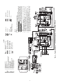
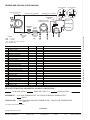
1
AQUAZONE™
50PSW036-360
Water-to-Water Source Heat Pump
with PURON® Refrigerant (R-410A)
Installation, Start-Up, and
Service Instructions
CONTENTS
Page
SAFETY CONSIDERATIONS . . . . . . . . . . . . . . . . . . .1,2
GENERAL . . . . . . . . . . . . . . . . . . . . . . . . . . . . . . . . . . . . . . . . 2
INSTALLATION . . . . . . . . . . . . . . . . . . . . . . . . . . . . . 2-16
Step 1 — Check Jobsite . . . . . . . . . . . . . . . . . . . . . . . . 2
Step 2 — Check Unit . . . . . . . . . . . . . . . . . . . . . . . . . . . 2
• STORAGE
• PROTECTION
• INSPECT UNIT
Step 3 — Locate Unit. . . . . . . . . . . . . . . . . . . . . . . . . . . . . 4
Step 4 — Mount Unit . . . . . . . . . . . . . . . . . . . . . . . . . . . . . 4
Step 5 — Connect Piping. . . . . . . . . . . . . . . . . . . . . . . . . 5
• WATER SUPPLY AND QUALITY
• WATER LOOP APPLICATIONS
• GROUND-WATER APPLICATIONS
• GROUND-LOOP APPLICATIONS
• UNIT LOAD PIPING
Step 6 — Wire Electrical Connections . . . . . . . . . . . . 7
• POWER CONNECTION
• SUPPLY VOLTAGE
• EXTERNAL LOOP POWER CONNECTION
• 208-V OPERATION
• 460-V OPERATION
Step 7 — Wire Low Voltage Connections . . . . . . . . 15
• THERMOSTAT CONNECTIONS
• WATER FREEZE PROTECTION
• ACCESSORY CONNECTIONS
• WATER SOLENOID VALVES
PRE-START-UP . . . . . . . . . . . . . . . . . . . . . . . . . . . . . . . . . . 16
System Checkout . . . . . . . . . . . . . . . . . . . . . . . . . . . . . 16
FIELD SELECTABLE INPUTS . . . . . . . . . . . . . . . .16,17
Complete C Control Jumper Settings. . . . . . . . . . . 16
Complete C Control DIP Switches. . . . . . . . . . . . . . 16
Deluxe D Control Jumper Settings . . . . . . . . . . . . . 16
Deluxe D Control DIP Switches . . . . . . . . . . . . . . . . 16
Deluxe D Control Accessory Relay
Configurations . . . . . . . . . . . . . . . . . . . . . . . . . . . . . 17
START-UP . . . . . . . . . . . . . . . . . . . . . . . . . . . . . . . . . . . . 17-19
Operating Limits . . . . . . . . . . . . . . . . . . . . . . . . . . . . . . . . 17
Unit Start-Up . . . . . . . . . . . . . . . . . . . . . . . . . . . . . . . . . . . . 17
Scroll Compressor Rotation. . . . . . . . . . . . . . . . . . . . . 17
Flow Regulation. . . . . . . . . . . . . . . . . . . . . . . . . . . . . . . . . 18
Cleaning and Flushing . . . . . . . . . . . . . . . . . . . . . . . . . . 18
Antifreeze . . . . . . . . . . . . . . . . . . . . . . . . . . . . . . . . . . . . . . . 18
Cooling Tower/Boiler Systems . . . . . . . . . . . . . . . . . . 19
Ground Coupled, Closed Loop and Plateframe
Heat Exchanger Well Systems . . . . . . . . . . . . . . . . 19
OPERATION . . . . . . . . . . . . . . . . . . . . . . . . . . . . . . . . . . .19,20
Power Up Mode . . . . . . . . . . . . . . . . . . . . . . . . . . . . . . . . . 19
Units with Aquazone Complete C Control . . . . . . . 19
Units with Aquazone Deluxe D Control . . . . . . . . . . 19
SYSTEM TEST . . . . . . . . . . . . . . . . . . . . . . . . . . . . . . . .20,21
Page
Test Mode . . . . . . . . . . . . . . . . . . . . . . . . . . . . . . . . . . . . . . . 20
Retry Mode. . . . . . . . . . . . . . . . . . . . . . . . . . . . . . . . . . . . . . 21
Aquazone Deluxe D Control LED Indicators . . . . . 21
SERVICE . . . . . . . . . . . . . . . . . . . . . . . . . . . . . . . . . . . . . .21,22
Water Coil . . . . . . . . . . . . . . . . . . . . . . . . . . . . . . . . . . . . . . . 21
Refrigerant System. . . . . . . . . . . . . . . . . . . . . . . . . . . . . . 21
Condenser Cleaning . . . . . . . . . . . . . . . . . . . . . . . . . . . . 21
Checking System Charge . . . . . . . . . . . . . . . . . . . . . . . 22
Refrigerant Charging. . . . . . . . . . . . . . . . . . . . . . . . . . . . 22
Air Coil Fan Motor Removal . . . . . . . . . . . . . . . . . . . . . 22
TROUBLESHOOTING . . . . . . . . . . . . . . . . . . . . . . . . 22-24
50PSW START-UP CHECKLIST . . . . . . . . . . . CL-1,CL-2
IMPORTANT: Read the entire instruction manual before
starting installation.
SAFETY CONSIDERATIONS
Installation and servicing of air-conditioning equipment can
be hazardous due to system pressure and electrical components. Only trained and qualified service personnel should
install, repair, or service air-conditioning equipment.
Untrained personnel can perform basic maintenance functions of cleaning coils and filters and replacing filters. All other
operations should be performed by trained service personnel.
When working on air-conditioning equipment, observe precautions in the literature, tags and labels attached to the unit, and
other safety precautions that may apply.
Improper installation, adjustment, alteration, service, maintenance, or use can cause explosion, fire, electrical shock or
other conditions which may cause personal injury or property
damage. Consult a qualified installer, service agency, or your
distributor or branch for information or assistance. The
qualified installer or agency must use factory-authorized kits or
accessories when modifying this product. Refer to the individual instructions packaged with the kits or accessories when
installing.
Follow all safety codes. Wear safety glasses and work
gloves. Use quenching cloth for brazing operations. Have fire
extinguisher available. Read these instructions thoroughly and
follow all warnings or cautions attached to the unit. Consult
local building codes and the National Electrical Code (NEC)
for special installation requirements.
Understand the signal words — DANGER, WARNING,
and CAUTION. DANGER identifies the most serious hazards
which will result in severe personal injury or death. WARNING signifies hazards that could result in personal injury or
death. CAUTION is used to identify unsafe practices, which
would result in minor personal injury or product and property
damage.
Manufacturer reserves the right to discontinue, or change at any time, specifications or designs without notice and without incurring obligations.
Catalog No. 04-53500054-01
Printed in U.S.A.
Form 50PSW-2SI
Pg 1
7-09
Replaces: 50PSW-1SI
Recognize safety information. This is the safety alert
symbol ( ). When you see this symbol on the unit and in
instructions or manuals, be alert to the potential for personal
injury.
Step 2 — Check Unit — Upon receipt of shipment at
the jobsite, carefully check the shipment against the bill of
lading. Make sure all units have been received. Inspect the carton or crating of each unit, and inspect each unit for damage.
Ensure the shipping company makes proper notation of any
shortages or damage on all copies of the freight bill. Concealed
damage not discovered during unloading must be reported to
the shipping company within 15 days of receipt of shipment.
NOTE: It is the responsibility of the purchaser to file all
necessary claims with the shipping company.
1. Verify unit is correct model for entering water temperature of job.
2. Be sure the location chosen for unit installation provides
ambient temperatures maintained above freezing. Well
water applications are especially susceptible to freezing.
3. Be sure the installation location is isolated from sleeping
areas, private offices and other acoustically sensitive
spaces.
NOTE: A sound control accessory package may be used
to help eliminate sound in sensitive spaces.
4. Provide sufficient access to allow maintenance and
servicing of the compressor and coils.
5. Provide an unobstructed path to the unit within the closet
or mechanical room. Space should be sufficient to allow
removal of unit if necessary.
6. Provide ready access to water valves and fittings, and
screwdriver access to unit side panels.
7. Where access to side panels is limited, pre-removal of the
control box side mounting screws may be necessary for
future servicing.
STORAGE — If the equipment is not needed for immediate
installation upon its arrival at the jobsite, it should be left in its
shipping carton and stored in a clean, dry area of the building
or in a warehouse. Units must be stored in an upright position
at all times. If carton stacking is necessary, stack units a maximum of 3 cartons high. Do not remove any equipment from its
shipping package until it is needed for installation.
WARNING
Electrical shock can cause personal injury or death. Before
installing or servicing system, always turn off main power
to system. There may be more than one disconnect switch.
Turn off accessory heater power if applicable. Install lockout tag.
GENERAL
The Aquazone™ 50PSW water source heat pump (WSHP)
is a single-package vertically mounted unit with electronic controls designed for year-round cooling and heating.
IMPORTANT: The installation of water source heat pump
units and all associated components, parts, and accessories
which make up the installation shall be in accordance with
the regulations of ALL authorities having jurisdiction and
MUST conform to all applicable codes. It is the responsibility of the installing contractor to determine and comply
with ALL applicable codes and regulations.
INSTALLATION
Step 1 — Check Jobsite — Installation, operation and
maintenance instructions are provided with each unit. Before
unit start-up, read all manuals and become familiar with the
unit and its operation. Thoroughly check out the system before
operation. Complete the inspections and instructions listed
below to prepare a unit for installation. See Table 1 for unit
physical data.
Units are designed for indoor installation only. Be sure to allow adequate space around the unit for servicing. See Fig. 1
and 2 for overall unit dimensions.
CAUTION
To avoid equipment damage, do not use these units as a
source of heating or cooling during the construction process. The mechanical components used in these units can
quickly become clogged with construction dirt and debris
which may cause system damage.
Table 1 — 50PSW Unit Physical Data
50PSW UNIT SIZE
NOMINAL CAPACITY (tons)
WEIGHT (lb)
Operating
Packaged
COMPRESSOR (qty)
REFRIGERANT TYPE
Factory Charge Per Circuit (lb)
CONNECTIONS, IPT (in.)
Commercial Load/Source
HWG Water In/Out
036
3
060
5
120
10
180
14
360
30
348
373
Scroll (1)
360
385
Scroll (1)
790
800
Scroll (1)
1330
1340
Scroll (2)
4.5
6.25
726
770
Scroll (2)
R-410A
6.25
14.9
14.9
1
11/2
3 /4
1/
2
LEGEND
HWG — Hot Water Generator
IPT — Internal Pipe Thread
TXV — Thermostatic Expansion Valve
2
N/A
NOTES:
1. Maximum working pressure on the base unit is 500 psig.
2. Units have a dual isolated compressor mounting.
3. Units have a balanced port expansion valve (TXV).
4. Insulated source and load water coils are standard.
5. Insulated refrigerant circuit is standard.
6. Compressor is on (green) light and fault on (red) light.
2
B
A
1.0
1.8
6
5
4
1.0
C
3
J
H
G
M
a50-8420
F
2
L
K
E
1
D
Optional
Service Access
Required
Service Access
SIZES 036,060
SIZES 036,060
7.3
A
B
1.7
5
2.7
3
1
6
4
2
1.3
C
Required
Service Access
Optional
Service Access
SIZE 120
SIZE 120
50PSW
UNIT
SIZE
036,060
120
OVERALL CABINET
1
2
Source (Outdoor)
WATER CONNECTIONS
3
4
Load (Indoor)
5
6
A
Depth
B
Width
C
Height
D
Water In
E
Water Out
F
Water In
G
Water Out
H
Return In
J
Water Out
30.6
30.6
25.4
52.9
33.0
37.0
2.70
25.2
9.4
25.2
19.4
30.1
24.5
30.1
27.9
34.9
30.4
34.9
LEGEND
HWG — Hot Water Generator
HACR — Heating, Air Conditioning, and Refrigeration
NOTES:
1. Dimensions shown inches.
2. HACR circuit breaker in U.S.A. only.
Fig. 1 — 50PSW036-120 Unit
3
ELECTRIC ACCESS PLUGS
HWG
K
L
M
Low
External Power
Voltage Pump
Supply
20.9
22.9
30.9
29.9
31.9
34.4
15.0
[381]
12.3
[313]
4.5
[114]
Top
Power Supply Wiring
1.375 x
2.0
[ 34.9 x
50.8] Double KO
Top
View
21.0
[533]
Source
Load
4.3
[108]
Header
Access
Panel
Control Wiring
1.125 x
1.375
28.6 x
34.9] Double KO
Electrical
Access
Panel
[
4.3
[108]
5.4
[138]
4.5
[114]
2” IPT Water Connections
15.0
[381]
Fault/Run Lights
Refrig.
Circuit
Access
Panel
63.2
[1604]
Compressor
Access
Panel
Side
Front
62.0
[1575]
Optional (Single Unit)
3ft (91cm) Additional
Service Access
Left
Side
View
45.1
[1146]
Minimum
3ft [91cm]
Required Service
Access
a50-8421
Front
View
NOTES:
1. Dimensions shown in inches [mm].
2. Front and side access is preferred for service
access. All components may be accessed from
the front of the unit.
26.3
[669]
Fig. 2 — 50PSW180,360 Unit
3. Wait to remove the packaging until the unit is ready for
installation.
4. Verify that the refrigerant tubing is free of kinks or dents,
and that it does not touch other unit components.
5. Inspect all electrical connections. Be sure connections are
clean and tight at the terminals.
6. Loosen bolts and remove shipping clamps on compressors equipped with external spring vibration isolators.
Compressors are internally spring-mounted.
7. Locate and verify any accessory kit located in compressor
section.
8. Remove any access panel screws that may be difficult to
remove once unit is installed.
PROTECTION — Once the units are properly positioned on
the jobsite, they must be covered with either a shipping carton,
vinyl film, or an equivalent protective covering. Open ends of
pipes stored on the jobsite must be capped. This precaution is
especially important in areas where painting, plastering, or
spraying of fireproof material, etc., is not yet complete. Foreign
material that is allowed to accumulate within the units can prevent proper start-up and necessitate costly clean-up operations.
Before installing any of the system components, be sure to
examine each pipe, fitting, and valve, and remove any dirt or
foreign material found in or on these components.
CAUTION
DO NOT store or install units in corrosive environments or
in locations subject to temperature or humidity extremes
(e.g., attics, garages, rooftops, etc.). Corrosive conditions
and high temperature or humidity can significantly reduce
performance, reliability, and service life. Always move
units in an upright position. Tilting units on their sides may
cause equipment damage.
Step 3 — Locate Unit — The following guidelines
should be considered when choosing a location for the WSHP:
• Units are for indoor use only.
• Provide sufficient space for water and electrical
connections.
• Locate unit in an area that allows for easy access and
removal of access panels.
• Allow enough space for service personnel to perform
maintenance.
INSPECT UNIT — To prepare the unit for installation, complete the procedures listed below:
1. Compare the electrical data on the unit nameplate with
ordering and shipping information to verify that the
correct unit has been shipped.
2. Verify that the unit is the correct model for the entering
water temperature of the job.
Step 4 — Mount Unit — Mount unit as shown in Fig. 3.
Rod attachments must be able to support the weight of the unit.
See Table 1 for unit operating weight.
4
Load Connections (Hot
Water/Chilled Water)
In addition to complying with any applicable codes, consider the following for system piping:
• Piping systems utilizing water temperatures below
50 F require 1/2-in. closed cell insulation on all piping
surfaces to eliminate condensation.
• All plastic to metal threaded fittings should be avoided
due to the potential to leak. Use a flange fitted substitute.
• Teflon* tape thread sealant is recommended to minimize
internal fouling of the heat exchanger.
• Use backup wrench. Do not overtighten connections.
• Route piping to avoid service access areas to unit.
• The piping system should be flushed prior to operation to
remove dirt and foreign materials from the system.
GROUND-WATER APPLICATIONS — In addition to
complying with any applicable codes, consider the following
for system piping:
• Install shut-off valves for servicing.
• Install pressure-temperature plugs to measure flow and
temperature.
• Boiler drains and other valves should be connected using
a “T” connector to allow acid flushing for the heat
exchanger.
• Do not overtighten connections.
• Route piping to avoid service access areas to unit.
• Use PVC SCH80 or copper piping material.
NOTE: PVC SCH40 should not be used due to system high
pressure and temperature extremes.
GROUND-LOOP APPLICATIONS — Temperatures between 25 and 110 F and a cooling capacity of 2.25 to 3 gpm of
flow per ton are recommended. In addition to complying with
any applicable codes, consider the following for system piping:
• Piping materials should be limited to only polyethylene
fusion in the buried sections of the loop.
• Galvanized or steel fittings should not be used at any
time due to corrosion.
• All plastic to metal threaded fittings should be avoided
due to the potential to leak. Use a flange fitted substitute.
• Do not overtighten connections.
• Route piping to avoid service access areas to unit.
• Pressure-temperature (P/T) plugs should be used to measure flow of pressure drop.
UNIT LOAD PIPING — For applications with wide temperature variation such as heating/cooling coils:
• Use piping materials that are rated for the maximum temperature and pressure combination. This excludes PVC
for most heating applications.
• Ensure load water flow in high temperature heating
applications is at least 3 gpm per ton to improve performance and reduce nuisance high pressure faults.
• DO NOT employ plastic to metal threaded joints.
• Utilize a pressure tank and air separator vent system to
equalize pressure and remove air.
• Employ an 800-micron particulate strainer in both load
and source plumbing to protect the plate heat exchanger.
Swimming Pool Hot Tub Applications — Load heat exchanger should be isolated with secondary heat exchanger
constructed of anti-corrosion material in all chlorine/bromine
fluid applications.
Potable Water Applications
• Load coax material should always be vented double
walled for use in potable water systems.
• Ensure load water flow in high temperature heating
applications is at least 3 gpm per ton to improve performance and reduce nuisance high pressure faults.
Automatic Flow
Regulator
Ball Valve
with Pressure
Temperature Port
Source Connections
(Boiler/Tower/Ground)
Ball Valve
with Pressure
Temperature Port
Y Strainer with
Blow Down Valve
Power
Disconnect
Control
Wiring
a50-8138
Fig. 3 — Typical Water Loop System —
Boiler, Tower, or Ground (Sizes 180,360 Shown)
Step 5 — Connect Piping — Depending on the appli-
cation, there are 3 types of WSHP piping systems to choose
from: water loop, ground-water and ground loop. Refer to the
Carrier System Design Manual for additional information.
All WSHP units utilize low temperature soldered female
pipe thread fittings for water connections to prevent annealing
and out-of-round leak problems which are typically associated
with high temperature brazed connections. When making piping connections, consider the following:
• A backup wrench must be used when making screw connections to unit to prevent internal damage to piping.
• Insulation may be required on piping to avoid condensation in the case where fluid in loop piping operates at
temperatures below dew point of adjacent air.
• Piping systems that contain steel pipes or fittings may
be subject to galvanic corrosion. Dielectric fittings may
be used to isolate the steel parts of the system to avoid
galvanic corrosion.
• Units may be manifolded together via top water connects
to get increased temperatures, when piped in series, or
greater capacity, when piped in parallel.
WATER SUPPLY AND QUALITY — Check water supply.
Water supply should be plentiful and of good quality. See
Table 2 for water quality guidelines.
IMPORTANT: Failure to comply with the above required
water quality and quantity limitations and the closedsystem application design requirements may cause damage
to the tube-in-tube heat exchanger that is not the responsibility of the manufacturer.
In all applications, the quality of the water circulated
through the heat exchanger must fall within the ranges listed in
the Water Quality Guidelines table. Consult a local water treatment firm, independent testing facility, or local water authority
for specific recommendations to maintain water quality within
the published limits.
WATER LOOP APPLICATIONS — Water loop applications usually include a number of units plumbed to a common
piping system. Maintenance to any of these units can introduce
air into the piping system. Therefore, air elimination
equipment comprises a major portion of the mechanical room
plumbing.
The flow rate is usually set between 2.25 and 3 gpm per ton
of cooling capacity. For proper maintenance and servicing,
pressure-temperature (P/T) ports are necessary for temperature
and flow verification.
*Teflon is a trademark of E. I. du Pont de Nemours and Company.
5
Table 2 — Water Quality Guidelines
HX
CLOSED
OPEN LOOP AND RECIRCULATING WELL**
MATERIAL*
RECIRCULATING†
Scaling Potential — Primary Measurement
Above the given limits, scaling is likely to occur. Scaling indexes should be calculated using the limits below.
pH/Calcium
All
N/A
pH < 7.5 and Ca Hardness, <100 ppm
Hardness Method
Index Limits for Probable Scaling Situations (Operation outside these limits is not recommended.)
Scaling indexes should be calculated at 150 F for direct use and HWG applications, and at 90 F for indirect HX use. A monitoring plan should be
implemented.
Ryznar Stability Index
6.0 - 7.5
All
N/A
If >7.5 minimize steel pipe use.
Langelier Saturation Index
–0.5 to +0.5
All
N/A
If <–0.5 minimize steel pipe use.
Based upon 150 F HWG and direct well, 85 F indirect well HX.
Iron Fouling
Iron Fe2+ (Ferrous)
<0.2 ppm (Ferrous)
(Bacterial Iron Potential)
All
N/A
If Fe2+ (ferrous) >0.2 ppm with pH 6 - 8, O2<5 ppm check for
iron bacteria.
Iron Fouling
<0.5 ppm of Oxygen
All
N/A
Above this level deposition will occur.
Corrosion Prevention††
pH
6 - 8.5
6 - 8.5
All
Monitor/treat as needed.
Minimize steel pipe below 7 and no open tanks with pH <8.
Hydrogen Sulfide (H2S)
<0.5 ppm
At H2S>0.2 ppm, avoid use of copper and cupronickel piping of HXs.
All
N/A
Rotten egg smell appears at 0.5 ppm level.
Copper alloy (bronze or brass) cast components are okay to <0.5 ppm.
Ammonia Ion as Hydrox<0.5 ppm
ide, Chloride, Nitrate and
All
N/A
Sulfate Compounds
Maximum Chloride Levels
Maximum allowable at maximum water temperature.
50 F (10 C)
75 F (24 C)
100 F (38 C)
Copper
N/A
<20 ppm
NR
NR
Cupronickel
N/A
<150 ppm
NR
NR
304 SS
N/A
<400 ppm
<250 ppm
<150 ppm
316 SS
N/A
<1000 ppm
<550 ppm
<375 ppm
Titanium
N/A
>1000 ppm
>550 ppm
>375 ppm
Erosion and Clogging
Particulate Size and
<10 ppm of particles and
Erosion
a maximum velocity of <10 ppm (<1 ppm “sandfree” for reinjection) of particles and a maxiAll
6 fps.
mum velocity of 6 fps. Filtered for maximum 800 micron size. Any parFiltered for maximum
ticulate that is not removed can potentially clog components.
800 micron size.
CONDITION
LEGEND
HWG— Hot Water Generator
HX — Heat Exchanger
N/A — Design Limits Not Applicable Considering Recirculating Potable Water
NR — Application Not Recommended
SS — Stainless Steel
††If the concentration of these corrosives exceeds the maximum
allowable level, then the potential for serious corrosion problems
exists.
Sulfides in the water quickly oxidize when exposed to air, requiring that no agitation occur as the sample is taken. Unless tested
immediately at the site, the sample will require stabilization with a
few drops of one Molar zinc acetate solution, allowing accurate
sulfide determination up to 24 hours after sampling. A low pH and
high alkalinity cause system problems, even when both values are
within ranges shown. The term pH refers to the acidity, basicity, or
neutrality of the water supply. Below 7.0, the water is considered
to be acidic. Above 7.0, water is considered to be basic. Neutral
water contains a pH of 7.0.
To convert ppm to grains per gallon, divide by 17. Hardness in
mg/l is equivalent to ppm.
*Heat exchanger materials considered are copper, cupronickel,
304 SS (stainless steel), 316 SS, titanium.
†Closed recirculating system is identified by a closed pressurized
piping system.
**Recirculating open wells should observe the open recirculating
design considerations.
6
conform to the Class II temperature limitations described in the
NEC.
Operating voltage must be the same voltage and phase as
shown in Table 3.
Refer to unit wiring diagrams Fig. 4-12 for a schematic of
the field connections which must be made by the installing (or
electrical) contractor.
Consult the unit wiring diagram located on the inside of the
compressor access panel to ensure proper electrical hookup.
The installing (or electrical) contractor must make the field
connections when using field-supplied disconnect.
Make all final electrical connections with a length of flexible conduit to minimize vibration and sound transmission to
the building.
POWER CONNECTION — Line voltage connection is
made by connecting incoming line voltage wires to L1, L2, and
L3 on the power distribution block.
Step 6 — Wire Electrical Connections
WARNING
To avoid possible injury or death due to electrical shock,
open the power supply disconnect switch and secure it in
an open position during installation. Install lockout tag.
CAUTION
Use only copper conductors for field-installed electrical
wiring. Unit terminals are not designed to accept other
types of conductors. Failure to heed this warning could
result in equipment damage.
All field-installed wiring, including the electrical ground,
MUST comply with the National Electrical Code (NEC) as
well as applicable local codes. In addition, all field wiring must
Table 3 — 50PSW Electrical Data
50PSW UNIT
SIZE
036
060
120
180
360
FLA
HACR
LRA
MCA
MOCP
RLA
—
—
—
—
—
—
VOLTAGE
(V-Ph-Hz)
VOLTAGE RANGE
MIN/MAX
208/230-1-60
265-1-60
208/230-3-60
460-3-60
575-3-60
208/230-1-60
208/230-3-60
460-3-60
575-3-60
208/230-1-60
208/230-3-60
460-3-60
575-3-60
208/230-3-60
460-3-60
575-3-60
208/230-3-60
460-3-60
575-3-60
187/254
239/292
187/254
414/506
518/633
187/254
187/254
414/506
518/633
187/254
187/254
414/506
518/633
187/254
414/506
518/633
187/254
414/506
518/633
COMPRESSOR
RLA
LRA
QTY
16.7
79.0
1
13.5
72.0
1
10.4
73.0
1
5.8
38.0
1
3.8
36.5
1
30.1
158.0
1
20.5
155.0
1
9.6
75.0
1
7.6
54.0
1
30.1
158.0
2
20.5
155.0
2
9.6
75.0
2
7.6
54.0
2
53.6
245.0
1
20.7
125.0
1
16.4
100.0
1
53.6
245.0
2
20.7
125.0
2
16.4
100.0
2
LEGEND
Full Load Amps
Heating, Air Conditioning, and Refrigeration
Locked Rotor Amps
Minimum Circuit Amps
Minimum Overcurrent Protection
Rated Load Amps
*Time-delay fuse or HACR circuit breaker.
NOTE: The 460-v units using an internal secondary pump will
require a neutral wire from the supply side in order to feed the
accessory with 265-v.
7
TOTAL
FLA
16.7
13.5
10.4
5.8
3.8
30.1
20.5
9.6
7.6
60.2
41.0
19.2
15.2
53.6
20.7
16.4
107.2
41.4
32.8
MCA
20.9
16.9
13.0
7.3
4.8
37.6
25.6
12.0
9.5
67.7
46.1
21.6
17.1
67.0
25.9
20.5
120.6
46.6
36.9
MOCP*
35
30
20
15
15
60
45
20
15
90
60
30
20
110
45
35
150
60
50
AL
CB
CC
COMP
FP1
FP2
HP
JW4
LED
LOC
NEC
P1
PDB
A50-8433
8
—
—
—
—
—
—
—
—
—
—
—
—
—
Complete
C
Complete
C
RVS
TRANS
Relay/Contactor Coil
COMPLETE C 2
COMPLETE C
COMPLETE C
COMPLETE C 1
5
*Optional.
NOTES:
1. Compressor motor thermally protected internally.
2. All wiring to the unit must comply with NEC and local codes.
3. Power Supply: 460 v and 575 v — Transformer is factory wired for 460 v and
575 v power supply with wire lead colors as shown in the chart. The transformer is 75 va and is protected with a circuit breaker in the secondary circuit.
4. Power Supply: 208-230 v — Transformer is factory wired for 208 v power
supply. For 230 v power supply, disconnect red lead at H2 and reconnect it at
H3. The transformer is 150 va and is protected with primary and secondary
fuses.
5. FP1 thermistor provides low temp protection for source water. When using
antifreeze solutions, cut JW3 jumper.
6. 24-v alarm signal shown. For dry alarm contact, cut JW1 jumper and dry contact will be available between AL1 and AL2.
7. Transformer secondary ground via Complete C board standoffs, and screws
to control box. (Ground available from top two standoffs as shown.)
8. Suffix 1 designates association with lead compressor, suffix 2 with lag compressor. Exception AL1, AL2, FP1, FP2, are per legend.
9. Refer to Thermostat Installation, Application and Operation Manual for control
wiring to the unit. Low voltage wiring must be “Class 1” and voltage rating
equal to or greater than unit supply voltage.
LE371
Low Pressure Switch
Ground
Indicator Light
G=Green, R=Red
(Comp On) (Alarm Light)
Fuse
High Pressure Switch
Thermistor
F
Circuit Breaker
Solenoid Coil
5
LEGEND
— Reversing Valve Solenoid
— Transformer
Factory Line Voltage Wiring
Factory Low Voltage Wiring
Field Line Voltage Wiring
Field Low Voltage Wiring
Printed Circuit Trace
Fig. 4 — Typical Aquazone™ 50PSW360 Complete C Control Wiring, 3-Phase
Alarm Relay Contacts
Circuit Breaker
Compressor Contactor
Compressor
Sensor, Source Low Temp Protection
Sensor, Load Low Temp Protection
High Pressure Switch
Jumper Wire for Alarm
Light-Emitting Diode
Loss of Charge Pressure Switch
National Electrical Code
Field Wiring Terminal Block
Power Distribution Block
AL
CAP
CC
FP1
FP2
HP
JW1
LOC
NEC
P1
RVS
TRANS
—
—
—
—
—
—
—
—
—
—
—
—
Relay/Contactor Coil
9
F
Fuse
Low Pressure Switch
High Pressure Switch
Circuit Breaker
Ground
Indicator Light
G=Green, R=Red
(Comp On) (Alarm Light)
Thermistor
Solenoid Coil
Complete C
NOTES:
1. Compressor thermally protected internally.
2. All wiring to the unit must comply with NEC and local codes.
3. Transformer is wired to 265-v (BRN) lead for 265-1-60 units. For 220-240-v or
230-v units, disconnect BRN lead at L1 and connect ORG lead to L1. Close
open end of BRN and RED leads with insulation tape. For 208-v unit, disconnect BRN lead at L1 and connect RED lead to L1. Close open ends of BRN
and ORG leads with insulation tape. Transformer is energy limiting or may
have circuit breaker.
4. FP1 thermistor provides freeze protection for source water. When using antifreeze solutions, cut JW3 jumper.
5. Check installation wiring information for controller hookup. Control wiring must
be Class 1 and voltage rating equal to or greater than unit supply voltage.
6. Transformer secondary ground via Complete C board standoff and screws to
control box. (Ground available from top 2 standoffs as shown.)
Fig. 5 — Typical Aquazone™ 50PSW036-180 Complete C Control Wiring, Single-Phase
Alarm Relay Contacts
Compressor Capacitor
Compressor Contactor
Sensor, Source Low Temp Protection
Sensor, Load Low Temp Protection
High Pressure Switch
Jumper Wire for Alarm
Loss of Charge Pressure Switch
National Electrical Code
Field Wiring Terminal Block
Reversing Valve Solenoid
Transformer
Factory Line Voltage Wiring
Factory Low Voltage Wiring
Field Line Voltage Wiring
Field Low Voltage Wiring
Printed Circuit Trace
LEGEND
a50-8422
Complete C
A50-8434
10
Complete
C
Complete
C
—
—
—
—
—
—
—
—
—
—
—
—
—
—
—
—
COMPLETE C 1
COMPLETE C
5
Alarm Relay Contacts
Circuit Breaker
Compressor Contactor
Compressor
Sensor, Source Low Temp Protection
Sensor, Load Low Temp Protection
High Pressure Switch
Jumper Wire for Alarm
Light-Emitting Diode
Loss of Charge Pressure Switch
Local Operating Network
National Electrical Code
Field Wiring Terminal Block
Power Distribution Block
Reversing Valve Solenoid
Transformer
Factory Line Voltage Wiring
Factory Low Voltage Wiring
Field Line Voltage Wiring
Field Low Voltage Wiring
Printed Circuit Trace
F
Fuse
Low Pressure Switch
High Pressure Switch
Circuit Breaker
Ground
Indicator Light
G=Green, R=Red
(Comp On) (Alarm Light)
Thermistor
Solenoid Coil
Relay/Contactor Coil
COMPLETE C
COMPLETE C 2
5
*Optional.
NOTES:
1. Compressor motor thermally protected internally.
2. All wiring to the unit must comply with NEC and local codes.
3. Power Supply: 460 v and 575 v — Transformer is factory wired for 460 v and
575 v power supply with wire lead colors as shown in the chart. The transformer is 75 va and is protected with a circuit breaker in the secondary circuit.
4. Power Supply: 208-230 v — Transformer is factory wired for 208 v power
supply. For 230 v power supply, disconnect red lead at H2 and reconnect it at
H3. The transformer is 150 va and is protected with primary and secondary
fuses.
5. FP1 thermistor provides low temp protection for source water. When using
antifreeze solutions, cut JW3 jumper.
6. Factory cut JW1 jumper. Dry contact will be available between AL1 and AL2.
7. Transformer secondary ground via Complete C board standoffs, and screws
to control box. (Ground available from top two standoffs as shown.)
8. Suffix 1 designates association with lead compressor, suffix 2 with lag compressor. Exception AL1, AL2, FP1, FP2, are per legend.
9. Refer to LON, or Thermostat Installation, Application and Operation Manual
for control wiring to the unit. Low voltage wiring must be “Class 1” and voltage
rating equal to or greater than unit supply voltage.
Fig. 6 — Typical Aquazone™ 50PSW360 Complete C and LON Controller Control Wiring, 3-Phase
AL
CB
CC
COMP
FP1
FP2
HP
JW4
LED
LOC
LON
NEC
P1
PDB
RVS
TRANS
LEGEND
AL
ASTAT
CB
CAP
CC
FP1
FP2
GND
HWG
HP
JW1
LOC
NEC
—
—
—
—
—
—
—
—
—
—
—
—
—
11
Complete C
P1
PDB
RVS
TRANS
—
—
—
—
Relay/Contactor Coil
Field Wiring Terminal Block
Power Distribution Block
Reversing Valve Solenoid
Transformer
Factory Line Voltage Wiring
Factory Low Voltage Wiring
Field Line Voltage Wiring
Field Low Voltage Wiring
Printed Circuit Trace
Low Pressure Switch
Ground
Indicator Light
G=Green, R=Red
(Comp On) (Alarm Light)
Complete C
Complete C
NOTES:
1. Compressor thermally protected internally.
2. All wiring to the unit must comply with NEC and local codes.
3. 208/230-v transformers will be connected for 208-v operation. For 230-v operation, disconnect RED lead at L1, and attach ORG lead to L1. Close open end
of RED lead with insulating tape. 380/420-v transformers will be connected for
380-v operation. For 420-v operation, disconnect VIO lead at L1, and attach
BRN lead to L1. Close open end of VIO lead with insulating tape.
4. FP1 thermistor provides freeze protection for source water. When using antifreeze solutions, cut JW3 jumper.
5. Typical heat pump thermostat wiring shown. Refer to thermostat installation
instructions for wiring to the unit. Thermostat wiring must be Class 1 and voltage rating equal to or greater than unit supply voltage.
6. Transformer secondary ground via Complete C board standoff and screws to
control box. (Ground available from top 2 standoffs as shown.)
7. Suffix 1 designates association with lead compressor. Suffix 2 designates lag
compressor. Exceptions are AL1, AL2, FP1, FP2.
Fuse
High Pressure Switch
Thermistor
F
Circuit Breaker
Solenoid Coil
Fig. 7 — Typical Aquazone™ 50PSW036-180 Complete C Control Wiring, 3-Phase
Complete C
Alarm Relay Contacts
Aquastat
Circuit Breaker
Compressor Capacitor
Compressor Contactor
Sensor, Source Low Temp Protection
Sensor, Load Low Temp Protection
Ground
Hot Water Generator
High Pressure Switch
Jumper Wire for Alarm
Loss of Charge Pressure Switch
National Electrical Code
LEGEND
Complete C 1
Complete C 2
a50-8423
AL
CB
CC
COMP
FP1
FP2
HP
JW4
LED
LOC
NEC
P1
PDB
A50-8136
12
Deluxe D
RVS
TRANS
LEGEND
Relay/Contactor Coil
DELUXE D 1
— Reversing Valve Solenoid
— Transformer
Factory Line Voltage Wiring
Factory Low Voltage Wiring
Field Line Voltage Wiring
Field Low Voltage Wiring
Printed Circuit Trace
DELUXE D
DELUXE D 2
DELUXE D
*Optional.
NOTES:
1. Compressor motor thermally protected internally.
2. All wiring to the unit must comply with NEC and local codes.
3. Power Supply: 460 v and 575 v — Transformer is factory wired for 460 v and
575 v power supply with wire lead colors as shown in the chart. The transformer is 75 va and is protected with a circuit breaker in the secondary circuit.
4. Power Supply: 208-230 v — Transformer is factory wired for 208 v power
supply. For 230 v power supply, disconnect red lead at H2 and reconnect it at
H3. The transformer is 150 va and is protected with primary and secondary
fuses.
5. FP1 thermistor provides low temp protection for source water. When using
antifreeze solutions, cut JW3 jumper.
6. 24-v alarm signal shown. For dry alarm contact, cut JW1 jumper and dry contact will be available between AL1 and AL2.
7. Transformer secondary ground via Deluxe D board standoffs, and screws to
control box. (Ground available from top two standoffs as shown.)
8. Suffix 1 designates association with lead compressor, suffix 2 with lag compressor. Exception AL1, AL2, FP1, FP2, are per legend.
9. Refer to Thermostat Installation, Application and Operation Manual for control
wiring to the unit. Low voltage wiring must be “Class 1” and voltage rating
equal to or greater than unit supply voltage.
LE371
Low Pressure Switch
Ground
Indicator Light
G=Green, R=Red
(Comp On) (Alarm Light)
Fuse
High Pressure Switch
Thermistor
F
Circuit Breaker
Solenoid Coil
Fig. 8 — Typical Aquazone™ 50PSW360 Deluxe D Control Wiring, 3-Phase
Alarm Relay Contacts
Circuit Breaker
Compressor Contactor
Compressor
Sensor, Source Low Temp Protection
Sensor, Load Low Temp Protection
High Pressure Switch
Jumper Wire for Alarm
Light-Emitting Diode
Loss of Charge Pressure Switch
National Electrical Code
Field Wiring Terminal Block
Power Distribution Block
Deluxe D
—
—
—
—
—
—
—
—
—
—
—
—
—
AL
CB
CC
COMP
FP1
FP2
HP
JW4
LED
LOC
LON
NEC
P1
A50-8137
13
—
—
—
—
—
—
—
—
—
—
—
—
—
Deluxe D
Deluxe D
PDB
RVS
TRANS
LEGEND
DELUXE D 1
— Power Distribution Block
— Reversing Valve Solenoid
— Transformer
Factory Line Voltage Wiring
Factory Low Voltage Wiring
Field Line Voltage Wiring
Field Low Voltage Wiring
Printed Circuit Trace
DELUXE D
F
Fuse
LE371
Low Pressure Switch
High Pressure Switch
Circuit Breaker
DELUXE D 2
DELUXE D
*Optional.
NOTES:
1. Compressor motor thermally protected internally.
2. All wiring to the unit must comply with NEC and local codes.
3. Power Supply: 460 v and 575 v — Transformer is factory wired for 460 v and
575 v power supply with wire lead colors as shown in the chart. The transformer is 75 va and is protected with a circuit breaker in the secondary circuit.
4. Power Supply: 208-230 v — Transformer is factory wired for 208 v power
supply. For 230 v power supply, disconnect red lead at H2 and reconnect it at
H3. The transformer is 150 va and is protected with primary and secondary
fuses.
5. FP1 thermistor provides low temp protection for source water. When using
antifreeze solutions, cut JW3 jumper.
6. Factory cut JW4 jumper. Dry contact will be available between AL1 and AL2.
7. Transformer secondary ground via Deluxe D board standoffs, and screws to
control box. (Ground available from top two standoffs as shown.)
8. Suffix 1 designates association with lead compressor, suffix 2 with lag compressor. Exception AL1, AL2, FP1, FP2, are per legend.
9. Refer to LON, or Thermostat Installation, Application and Operation Manual
for control wiring to the unit. Low voltage wiring must be “Class 1” and voltage
rating equal to or greater than unit supply voltage.
Ground
Indicator Light
G=Green, R=Red
(Comp On) (Alarm Light)
Thermistor
Solenoid Coil
Relay/Contactor Coil
Fig. 9 — Typical Aquazone™ 50PSW360 Deluxe D and LON Controller Control Wiring, 3-Phase
Alarm Relay Contacts
Circuit Breaker
Compressor Contactor
Compressor
Sensor, Source Low Temp Protection
Sensor, Load Low Temp Protection
High Pressure Switch
Jumper Wire for Alarm
Light-Emitting Diode
Loss of Charge Pressure Switch
Local Operating Network
National Electrical Code
Field Wiring Terminal Block
COMPLETE
C
CONTROL
PREMIER
LINK
PWR
Y
HS1/EXH/RVS
W
CR
CR
O
G
R
LEGEND
CR — Control Relay
LWT — Leaving Water Temperature Sensor
SAT — Supply Air Temperature Sensor
SPT — Space Temperature Sensor
NOTE: Reversing valve is on in Cooling mode.
C
CMP1
FAN
AL2
PWR
J1
J8
AL1
A
J5
J6
S
A
T
CMPSAFE
S
P
T
J4
L
W
T
Fig. 10 — PremierLink™ Controller Applications with Complete C Control
PREMIER
LINK
PWR
DELUXE
D
CONTROL
Y1
HS2
Y2
HS1
LEGEND
LWT — Leaving Water Temperature Sensor
SAT — Supply Air Temperature Sensor
SPT — Space Temperature Sensor
NOTE: Reversing valve is on in Cooling mode.
W1
O/W2
CMP2
G
CMP1
FAN
C
PWR
J1
J8
R
J5
J6
S
A
T
L
W
T
J4
CMPSAFE
S
P
T
AL1
Fig. 11 — PremierLink Controller Applications with Deluxe D Control
14
460-VOLT OPERATION — Units using 460-v and internal
secondary pump will require a neutral wire from the supply
side in order to feed accessory with 265-v.
Step 7 — Wire Low Voltage Connections
L1 L2 L3
THERMOSTAT CONNECTIONS
The thermostat should be wired directly to the Aquazone™
control board. See Fig. 4-9.
WATER FREEZE PROTECTION — The Aquazone control
allows the field selection of source fluid freeze protection
points through jumpers. The factory setting of jumper JW3
(FP1) is set for water at 30 F. In earth loop applications, jumper
JW3 should be clipped to change the setting to 10 F when
using antifreeze in colder earth loop applications. See Fig. 13.
Transformer
Low Voltage
Connector
Grnd Power Distribution
Block
C Control #1
Contactor -CC2
Low Voltage
Connector
Contactor -CC1
C Control #2
Fig. 12 — Typical Field Wiring
SUPPLY VOLTAGE — Operating voltage to unit must be
within voltage range indicated on unit nameplate.
Voltages between phases must be balanced within 2%.
Use the following formula to determine the percentage voltage
imbalance:
% Voltage Imbalance
max voltage deviation from average voltage
average voltage
Example: Supply voltage is 460-3-60.
AB = 452-v
BC = 464-v
AC = 455-v
= 100 x
Average Voltage =
=
452 + 464 + 455
3
1371
3
Fig. 13 — Typical Aquazone Control Board
Jumper Locations (Complete C Control Shown)
= 457
Determine maximum deviation from average voltage:
(AB) 457 – 452 = 5-v
(BC) 464 – 457 = 7-v
(AC) 457 – 455 = 2-v
Maximum deviation is 7-v.
Determine percent voltage imbalance.
% Voltage Imbalance = 100 x
ACCESSORY CONNECTIONS — The terminal labeled A
on the control is provided to control accessory devices such as
water valves, electronic air cleaners, humidifiers, etc. This signal operates with the compressor terminal. See Fig. 14. Refer
to the specific unit wiring schematic for details.
Terminal Strip
7
457
C
= 1.53%
This amount of phase imbalance is satisfactory as it is
below the maximum allowable 2%.
Operation on improper line voltage or excessive phase
imbalance constitutes abuse and may cause damage to electrical components.
NOTE: If more than 2% voltage imbalance is present, contact
local electric utility.
EXTERNAL LOOP POWER CONNECTION — If the unit
is to be connected to an external loop pump or flow controller,
connect the pump to the loop pump terminal block PB1. The
maximum power handling is 4 amps at 240-v. The pumps will
automatically cycle as required by the unit.
208-V OPERATION — All 208/240-v units are factory
wired for 208-v. The transformers may be switched to 240-v
operation (as illustrated on the wiring diagram) by switching
the red (208-v) wire with the orange (240-v) wire at the L2
terminal.
24 VAC
Typical
Water
Valve
A
Fig. 14 — Typical Aquazone Accessory Wiring
(Deluxe D Control Shown)
NOTE: The A terminal should only be used with 24-v signals,
not line voltage signals.
IMPORTANT: Two-compressor units with Complete C or
Deluxe D controls wired to terminal A will be turned off if
the controls are in lockout mode, even if the other board is
in normal operating mode.
15
STAGE 2 — DIP switch 2 will enable or disable compressor
delay. Set DIP switch to OFF for Stage 2 in which the compressor will have a 3-second delay before energizing. DIP switch 3
is not used. DIP switch 4 is not used. DIP switch 5 is used to
initiate one or 3 tries for the FP1 fault. If water freeze protection for the water coil is needed, then DIP switch 5 can be set to
lock out on the FP1 fault after one try.
WATER SOLENOID VALVES — Water solenoid valves
may be used on variable flow systems and ground water installations. A typical well water control valve wiring which can
limit waste water in a lockout condition is shown in Fig. 14. A
slow closing valve may be required to prevent water hammer.
When using a slow closing valve, special wiring conditions
need to be considered. The valve takes approximately 60 seconds to open (very little water will flow before 45 seconds) and
it activates the compressor only after the valve is completely
opened by closing its end switch. When wired as shown, the
valve will have the following operating characteristics:
1. Remain open during a lockout.
2. Draw approximately 25 to 35-va through the “Y” signal
of the thermostat.
Deluxe D Control Jumper Settings (See
Fig. 8 and 9)
WATER COIL FREEZE PROTECTION (FP1) LIMIT
SETTING — Select jumper 3, (JW3-FP1 Low Temp) to
choose FP1 limit of 10 F or 30 F. To select 30 F as the limit,
DO NOT clip the jumper. To select 10 F as the limit, clip the
jumper.
ALARM RELAY SETTING — Select jumper 4 (JW4-AL2
Dry) for connecting alarm relay terminal (AL2) to 24 vac (R)
or to remain as a dry contact (no connection). To connect AL2
to R, do not clip the jumper. To set as dry contact, clip the
jumper.
LOW PRESSURE SETTING — The Deluxe D control can
be configured for Low Pressure Setting (LP). Select jumper 1
(JW1-LP Norm Open) for choosing between low pressure input normally opened or closed. To configure for normally
closed operation, do not clip the jumper. To configure for normally open operation, clip the jumper.
IMPORTANT: This can overheat the anticipators of
electromechanical thermostats. Only use relay based
electronic thermostats.
PRE-START-UP
System Checkout — When the installation is complete,
follow the system checkout procedure outlined below before
starting up the system. Be sure:
1. Voltage is within the utilization range specifications of the
unit compressor and fan motor, and voltage is balanced
for 3-phase units.
2. Fuses, breakers and wire are correct size.
3. Low voltage wiring is complete.
4. Piping and system flushing is complete.
5. Air is purged from closed loop system.
6. System is balanced as required. Monitor if necessary.
7. Isolation valves are open.
8. Water control valves or loop pumps are wired.
9. Transformer switched to lower voltage tap if necessary.
10. Service/access panels are in place.
11. Control field-selected settings are correct.
Deluxe D Control DIP Switches — The Deluxe D
control has 2 DIP switch blocks. Each DIP switch block has 8
switches and is labeled either S1 or S2 on the circuit board. See
Fig. 8 and 9.
DIP SWITCH BLOCK 1 (S1) — This set of switches offers
the following options for Deluxe D control configuration:
Performance Monitor (PM) — Set switch 1 to enable or disable performance monitor. To enable the PM, set the switch to
ON. To disable the PM, set the switch to OFF.
Compressor Relay Staging Operation — Switch 2 will enable or disable compressor relay staging operation. The compressor relay can be set to turn on with Stage 1 or Stage 2 call
from the thermostat. This setting is used with dual stage units
(units with 2 compressors and 2 Deluxe D controls) or in master/slave applications. In master/slave applications, each compressor and fan will stage according to its switch 2 setting. If
switch is set to Stage 2, the compressor will have a 3-second
delay before energizing during Stage 2 demand.
NOTE: If DIP switch is set for Stage 2, the alarm relay will not
cycle during Test mode.
Heating/Cooling Thermostat Type — Switch 3 provides selection of thermostat type. Heat pump or heat/cool thermostats
can be selected. Select OFF for heat/cool thermostats. When in
heat/cool mode, Y1 is used for cooling Stage 1, Y2 is used for
cooling Stage 2, W1 is used for heating Stage 1 and O/W2 is
used for heating Stage 2. Select ON for heat pump applications.
In heat pump mode, Y1 used is for compressor Stage 1, Y2 is
used for compressor Stage 2, W1 is used for heating Stage 3 or
emergency heat, and O/W2 is used for RV (heating or cooling)
depending upon switch 4 setting.
O/B Thermostat Type — Switch 4 provides selection for heat
pump O/B thermostats. O is cooling output. B is heating output. Select ON for heat pumps with O output. Select OFF for
heat pumps with B output.
Dehumidification Fan Mode — Switch 5 provides selection
of normal or dehumidification fan mode. Select OFF for dehumidification mode. The fan speed relay will remain OFF during cooling Stage 2. Select ON for normal mode. The fan speed
relay will turn on during cooling Stage 2 in normal mode.
Switches 6, 7, 8 — Not used.
FIELD SELECTABLE INPUTS
Jumpers and DIP (dual in-line package) switches on the
control board are used to customize unit operation and can be
configured in the field.
IMPORTANT: Jumpers and DIP switches should only
be clipped when power to control board has been turned
off.
Complete C Control Jumper Settings (See
Fig. 4-7)
WATER COIL FREEZE PROTECTION (FP1) LIMIT
SETTING — Select jumper 3, (JW3-FP1 Low Temp) to
choose FP1 limit of 10 F or 30 F. To select 30 F as the limit,
DO NOT clip the jumper. To select 10 F as the limit, clip the
jumper.
ALARM RELAY SETTING — Select jumper 1 (JW1-AL2
Dry) for connecting alarm relay terminal (AL2) to 24 vac (R)
or to remain as a dry contact (no connection). To connect AL2
to R, do not clip the jumper. To set as dry contact, clip the
jumper.
Complete C Control DIP Switches — The
Complete C control has one DIP switch block with five
switches. See Fig. 4-7.
PERFORMANCE MONITOR (PM) — DIP switch 1 will
enable or disable this feature. To enable the PM, set the switch
to ON. To disable the PM, set the switch to OFF.
DIP SWITCH BLOCK 2 (S2) — Not used.
16
POWER SUPPLY — A voltage variation of ± 10% of nameplate utilization voltage is acceptable.
UNIT STARTING CONDITIONS — All units start and operate in an ambient of 45 F with entering air at 40 F and entering water at 20 F.
NOTE: These operating conditions are not normal or continuous operating conditions. It is assumed that start-up is for the
purpose of bringing the building space up to occupancy
temperature.
Deluxe D Control Accessory Relay Configurations (See Tables 4 and 5) — The following acces-
sory relay settings are applicable for Deluxe D control only:
CYCLE WITH COMPRESSOR — In this configuration, the
relay will be ON any time the compressor relay is on.
DIGITAL NIGHT SETBACK (NSB) — In this configuration, the relay will be ON if the NSB input is connected to
ground C.
NOTE: If there are no relays configured for digital NSB, then
the NSB and OVR inputs are automatically configured for
mechanical operation.
MECHANICAL NIGHT SETBACK — When NSB input is
connected to ground C, all thermostat inputs are ignored. A
thermostat setback heating call will then be connected to the
OVR input. If OVR input becomes active, then the Deluxe D
control will enter night low limit (NLL) staged heating mode.
The NLL staged heating mode will then provide heating during
the NSB period.
WATER VALVE (SLOW OPENING) — If relay is configured for water valve (slow opening), the relay will start 60 seconds prior to starting compressor relay.
WARNING
When the disconnect switch is closed, high voltage is
present in some areas of the electrical panel. Exercise caution when working with the energized equipment.
Table 6 — 50PSW Unit Operating Limits
WATER LIMITS
SOURCE COIL
Min Entering Water
Normal Entering Water
Max Entering Water
LOAD COIL
Min Entering Water
Normal Entering Water
Max Entering Water
CAUTION
To avoid equipment damage, DO NOT leave system filled
in a building without heat during the winter unless antifreeze is added to system water. Condenser coils never
fully drain by themselves and will freeze unless winterized
with antifreeze.
Digital NSB
Water Valve — Slow Opening
20
60
70
50
60
90
60
100
120
Turn off all power to unit.
Adjust all valves to full open position.
Restore power to unit.
Operate each unit in the cooling cycle. See Table 6 for
unit entering water temperatures.
5. Operate each heat pump in the heating cycle immediately
after checking cooling cycle operation.
NOTE: A time delay will prevent the compressor from
re-starting for approximately 5 minutes. The time delay
function can be overridden on the Complete C control
board.
6. If unit fails to operate, perform the following system
checks:
a. Check the voltage and current. Be sure they comply with electrical data on unit nameplate.
b. Check for loose terminal screws where wire connections have been made on both the line and lowvoltage terminal boards.
c. Check the supply and return piping. Be sure they
are properly connected to the inlet and outlet connections on the unit.
d. If the checks described above fail to reveal the
problem and the unit still will not operate, contact
a trained service technician to ensure proper
diagnosis.
DIP SWITCH POSITION
1
2
3
Off
On
On
On
Off
On
NOTE: All other DIP switch combinations are invalid.
Table 5 — DIP Switch Block S2 —
Accessory 2 Relay Options
Digital NSB
Water Valve — Slow Opening
50
85
110
1.
2.
3.
4.
LEGEND
NSB — Night Setback
ACCESSORY 2
RELAY OPTIONS
HEATING
(F)
Unit Start-Up
Table 4 — DIP Switch Block S2 —
Accessory 1 Relay Options
ACCESSORY 1
RELAY OPTIONS
COOLING
(F)
DIP SWITCH POSITION
4
5
6
Off
On
On
On
Off
On
LEGEND
NSB — Night Setback
NOTE: All other DIP switch combinations are invalid.
START-UP
Use the procedure outlined below to initiate proper unit
start-up.
NOTE: This equipment is designed for indoor installation
only.
Scroll Compressor Rotation — It is important to be
certain compressor is rotating in the proper direction. To
determine whether or not compressor is rotating in the proper
direction:
1. Connect service gages to suction and discharge pressure
fittings.
2. Energize the compressor.
3. The suction pressure should drop and the discharge
pressure should rise, as is normal on any start-up.
Operating Limits (See Table 6)
ENVIRONMENT — This equipment is designed for indoor
installation ONLY. Extreme variations in temperature, humidity and corrosive water or air will adversely affect the unit performance, reliability and service life.
17
If the suction pressure does not drop and the discharge
pressure does not rise to normal levels:
1. Turn off power to the unit. Install disconnect tag.
2. Reverse any two of the unit power leads.
3. Reapply power to the unit and verify pressures are correct. The suction and discharge pressure levels should
now move to their normal start-up levels.
Cleaning and Flushing — Cleaning and flushing of
the piping system is the single most important step to ensure
proper start-up and continued efficient operation of the system.
WARNING
To avoid possible injury or death due to electrical shock,
open the power supply disconnect switch and secure it in
an open position before flushing system. Install lockout
tag.
CAUTION
When the compressor is rotating in the wrong direction, the
unit makes an elevated level of noise and does not provide
cooling. Damage to compressor will occur if allowed to
operate in this manner.
Follow the instructions below to properly clean and flush
the system:
1. Verify electrical power to the unit is disconnected and
lockout tag installed.
2. Install the system with the supply hose connected directly
to the return riser valve. Use a single length of flexible
hose.
3. Open all air vents. Fill the system with the water. DO
NOT allow system to overflow. Bleed all air from the
system. Pressurize and check the system for leaks and repair appropriately.
4. Verify all strainers are in place. Start the pumps, and systematically check each vent to ensure all air is bled from
the system.
5. Verify make-up water is available. Adjust make-up water
appropriately to replace the air which was bled from the
system. Check and adjust the water/air level in the expansion tank.
6. Raise the loop temperature to approximately 85 F. Open
the drain at the lowest point in the system. Adjust the
make-up water replacement rate to equal the rate of bleed.
7. Refill the system and add trisodium phosphate in a proportion of approximately one pound per 150 gal. of water
(or other equivalent approved cleaning agent).
After a few minutes of reverse operation, the scroll compressor internal overload protection will open, thus activating
the unit lockout. This requires a manual reset. To reset, turn the
thermostat on and then off.
NOTE: There is a 5-minute time delay before the compressor
will start.
Flow Regulation — Flow regulation can be accomplished by two methods. Most water control valves have a flow
adjustment built into the valve. By measuring the pressure drop
through the unit heat exchanger, the flow rate can be determined. Adjust the water control valve until the flow of 1.5 to
2 gpm is achieved. Since the pressure constantly varies, two
pressure gages may be needed in some applications. See
Table 7 for heat exchanger pressure drops.
An alternative method is to install a flow control device.
These devices are typically an orifice of plastic material designed to allow a specified flow rate that are mounted on the
outlet of the water control valve. Occasionally these valves
produce a velocity noise that can be reduced by applying some
back pressure. To accomplish this, slightly close the leaving
isolation valve of the water regulating device.
CAUTION
Table 7 — Heat Exchanger Pressure Drop
Load/Outdoor Coax
UNIT
50PSW
036
060
120
180
360
GPM
5.0
7.0
9.0
7.5
11.3
15.0
15.0
22.6
30.0
18.0
27.0
35.0
35.0
53.0
70.0
30° F
4.2
5.8
8.4
3.1
5.0
7.4
4.3
7.0
10.3
0.8
2.7
4.8
1.6
4.0
7.2
PRESSURE DROP (psi)
50° F
70° F
2.3
1.6
4.1
2.9
5.3
4.6
1.9
1.4
3.4
2.9
5.6
4.6
2.6
2.0
4.8
3.9
7.8
6.4
0.4
0.2
1.7
1.5
3.3
3.0
1.2
1.0
3.6
3.3
6.5
5.9
To avoid possible damage to a plastic (PVC) piping system, do not allow temperatures to exceed 110 F.
90° F
1.3
2.6
4.3
1.1
2.2
3.9
1.6
3.1
5.3
0.1
1.4
2.8
0.9
3.0
5.5
8.
9.
10.
Source/Outdoor Coax
UNIT
50PSW
036
060
120
180
360
GPM
5.0
7.0
9.0
7.5
11.3
15.0
15.0
22.6
30.0
18.0
27.0
35.0
35.0
53.0
70.0
30° F
4.2
5.8
8.4
3.1
5.0
7.4
4.3
7.0
10.3
0.8
2.7
4.8
1.6
4.0
7.2
PRESSURE DROP (psi)
50° F
70° F
2.6
2.3
4.1
4.1
6.0
5.5
2.2
1.9
4.0
3.6
6.1
5.5
3.1
2.7
5.6
5.0
8.5
7.7
0.4
0.2
1.7
1.5
3.3
3.0
1.2
1.0
3.6
3.3
6.5
5.9
11.
90° F
1.8
3.1
4.9
1.5
3.1
5.0
2.1
4.3
7.0
0.1
1.4
2.8
0.9
3.0
5.5
Raise the loop temperature to 100 F. Circulate the solution for a minimum of 8 to 24 hours. At the end of this
period, shut off the circulating pump and drain the solution. Repeat system cleaning if desired.
When the cleaning process is complete, remove the shortcircuited hose. Reconnect the hoses to the proper supply,
and return the connections to each of the units. Refill the
system and bleed off all air.
Test the system pH with litmus paper. The system water
should be slightly alkaline (pH of 7.5 to 8.5). Add chemicals, as appropriate, to maintain acidity levels.
When the system is successfully cleaned, flushed, refilled
and bled, restore power.
Check the main system panels, safety cutouts and alarms.
Set the controls to properly maintain loop temperatures.
CAUTION
DO NOT use “Stop Leak” or any similar chemical agent in
this system. Addition of these chemicals to the loop water
will foul the system and inhibit unit operation.
Antifreeze — In areas where entering loop temperatures
drop below 40 F or where piping will be routed through areas
subject to freezing, antifreeze is needed.
18
Alcohols and glycols are commonly used as antifreeze
agents. Freeze protection should be maintained to 15 F below
the lowest expected entering loop temperature. For example, if
the lowest expected entering loop temperature is 30 F, the leaving loop temperature would be 22 to 25 F. Therefore, the freeze
protection should be at 15 F (30 F – 15 F = 15 F).
OPERATION
Power Up Mode — The unit will not operate until all the
inputs, terminals and safety controls are checked for normal
operation.
NOTE: The compressor will have a 5-minute anti-short cycle
upon power up.
IMPORTANT: All alcohols should be pre-mixed and
pumped from a reservoir outside of the building or
introduced under water level to prevent alcohols from
fuming.
Units with Aquazone™ Complete C Control
STANDBY — The Y and W terminals are not active in Standby mode, however the O and G terminals may be active, depending on the application. The compressor will be off.
COOLING — The Y and O terminals are active in Cooling
mode. After power up, the first call to the compressor will initiate a 5 to 80 second random start delay and a 5-minute antishort cycle protection time delay. After both delays are complete, the compressor is energized.
NOTE: On all subsequent compressor calls the random start
delay is omitted.
HEATING STAGE 1 — Terminal Y is active in heating
Stage 1. After power up, the first call to the compressor will
initiate a 5 to 80 second random start delay and a 5-minute antishort cycle protection time delay. After both delays are
complete, the compressor is energized.
NOTE: On all subsequent compressor calls the random start
delay is omitted.
HEATING STAGE 2 — To enter Stage 2 mode, terminal W is
active (Y is already active). Also, the G terminal must be active
or the W terminal is disregarded. The compressor relay will remain on and EH1 (emergency heat) is immediately turned on.
EH2 will turn on after 10 minutes of continual Stage 2 demand.
NOTE: EH2 will not turn on (or if on, will turn off) if FP1
(freeze protection) temperature is greater than 45 F and FP2 is
greater than 110 F.
EMERGENCY HEAT — In emergency heat (EH) mode, terminal W is active while terminal Y is not. Terminal G must be
active or the W terminal is disregarded. EH1 is immediately
turned on. EH2 will turn on after 5 minutes of continual emergency heat demand.
Calculate the total volume of fluid in the piping system. See
Table 8. Use the percentage by volume in Table 9 to determine
the amount of antifreeze to use. Antifreeze concentration
should be checked from a well mixed sample using a hydrometer to measure specific gravity.
FREEZE PROTECTION SELECTION — The 30 F FP1
factory setting (water) should be used to avoid freeze damage
to the unit.
Once antifreeze is selected, the JW3 jumper (FP1) should
be clipped on the control to select the low temperature (antifreeze 10 F) set point to avoid nuisance faults.
Table 8 — Approximate Fluid Volume (gal.)
per 100 Ft of Pipe
PIPE
Copper
Rubber Hose
Polyethylene
DIAMETER (in.)
1
1.25
1.5
1
3/ IPS SDR11
4
1 IPS SDR11
1
1 /4 IPS SDR11
1/ IPS SDR11
2
2 IPS SDR11
1
1 /4 IPS SCH40
11/2 IPS SCH40
2 IPS SCH40
VOLUME (gal.)
4.1
6.4
9.2
3.9
2.8
4.5
8.0
10.9
18.0
8.3
10.9
17.0
LEGEND
IPS — Internal Pipe Size
SCH — Schedule
SDR — Standard Dimensional Ratio
Units with Aquazone Deluxe D Control
STANDBY/FAN ONLY — The compressor will be off. The
fan enable, fan speed, and reversing valve (RV) relays will be
on if inputs are present. If there is a Fan 1 demand, the fan enable will immediately turn on. If there is a Fan 2 demand, the
fan enable and fan speed will immediately turn on.
NOTE: DIP switch 5 on S1 does not have an effect upon Fan 1
and Fan 2 outputs.
HEATING STAGE 1 — In Heating Stage 1 mode, the fan enable and compressor relays are turned on immediately. Once
the demand is removed, the relays are turned off and the control reverts to standby mode. If there is a master/slave or dual
compressor application, all compressor relays and related functions will operate per their associated DIP switch 2 setting on
S1.
HEATING STAGE 2 — In Heating Stage 2 mode, the fan enable and compressor relays remain on. The fan speed relay is
turned on immediately and turned off immediately once the demand is removed. The control reverts to Heating Stage 1 mode.
If there is a master/slave or dual compressor application, all
compressor relays and related functions will operate per their
associated DIP switch 2 setting on S1.
HEATING STAGE 3 — In Heating Stage 3 mode, the fan enable, fan speed and compressor relays remain on. The EH1 output is turned on immediately. With continuing Heat Stage 3 demand, EH2 will turn on after 10 minutes. EH1 and EH2 are
turned off immediately when the Heating Stage 3 demand is removed. The control reverts to Heating Stage 2 mode.
NOTE: Volume of heat exchanger is approximately 1.0 gallon.
Table 9 — Antifreeze Percentages by Volume
ANTIFREEZE
Methanol (%)
100% USP Food Grade
Propylene Glycol (%)
MINIMUM TEMPERATURE FOR
FREEZE PROTECTION (F)
10
15
20
25
25
21
16
10
38
30
22
15
Cooling Tower/Boiler Systems — These systems
typically use a common loop maintained at 60 to 90 F. The use
of a closed circuit evaporative cooling tower with a secondary
heat exchanger between the tower and the water loop is recommended. If an open type cooling tower is used continuously,
chemical treatment and filtering will be necessary.
Ground Coupled, Closed Loop and Plateframe
Heat Exchanger Well Systems — These systems al-
low water temperatures from 30 to 110 F. The external loop
field is divided up into 2 in. polyethylene supply and return
lines. Each line has valves connected in such a way that upon
system start-up, each line can be isolated for flushing using only
the system pumps. Air separation should be located in the piping system prior to the fluid re-entering the loop field.
19
Output EH2 will be off if FP1 is greater than 45 F and FP2
(when shorted) is greater than 110 F during Heating Stage 3
mode. This condition will have a 30-second recognition time.
Also, during Heating Stage 3 mode, EH1, EH2, fan enable, and
fan speed will be ON if G input is not active.
EMERGENCY HEAT — In emergency heat mode, the fan
enable and fan speed relays are turned on. The EH1 output is
turned on immediately. With continuing emergency heat demand, EH2 will turn on after 5 minutes. Fan enable and fan
speed relays are turned off after a 60-second delay. The control
reverts to standby mode.
Output EH1, EH2, fan enable, and fan speed will be ON if
the G input is not active during emergency heat mode.
COOLING STAGE 1 — In Cooling Stage 1 mode, the fan
enable, compressor and RV relays are turned on immediately.
If configured as stage 2 (DIP switch set to OFF) then the compressor and fan will not turn on until there is a stage 2 demand.
The fan enable and compressor relays are turned off immediately when the Cooling Stage 1 demand is removed. The control reverts to standby mode. The RV relay remains on until
there is a heating demand. If there is a master/slave or dual
compressor application, all compressor relays and related functions will track with their associated DIP switch 2 on S1.
COOLING STAGE 2 — In Cooling Stage 2 mode, the fan
enable, compressor and RV relays remain on. The fan speed relay is turned on immediately and turned off once the Cooling
Stage 2 demand is removed. The control reverts to Cooling
Stage 1 mode. If there is a master/slave or dual compressor application, all compressor relays and related functions will track
with their associated DIP switch 2 on S1.
NIGHT LOW LIMIT (NLL) STAGED HEATING — In NLL
staged heating mode, the override (OVR) input becomes
active and is recognized as a call for heating and the control
will immediately go into a Heating Stage 1 mode. With an
additional 30 minutes of NLL demand, the control will go into
Heating Stage 2 mode. With another additional 30 minutes of
NLL demand, the control will go into Heating Stage 3 mode.
Table 10 — Complete C Control Current LED
Status and Alarm Relay Operations
LED STATUS
CCG
CC
C
R
C
Off
Control is non-functional
Fault Retry
Slow Flash
Over/Under
Voltage Shutdown
Fast Flash
Flashing
Code 1
Flashing
Code 2
Flashing
Code 3
Flashing
Code 4
Flashing
Code 5
Flashing
Code 6
Flashing
Code 7
Flashing
Code 8
Flashing
Code 9
Lockout
Test Mode — No fault
in memory
Test Mode — HP Fault
in memory
Test Mode — LP Fault
in memory
Test Mode — FP1 Fault
in memory
Test Mode — FP2 Fault
in memory
Test Mode — CO Fault
in memory
Test Mode — Over/Under
shutdown in memory
Test Mode — PM
in memory
Test Mode — FP1/FP2
swapped fault in memory
—
—
—
—
—
—
Open
Cycle
(Closed 5 sec.,
Open 25 sec.)
Open
Open
Open
(Closed after
15 minutes)
Closed
Cycling Code 1
Cycling Code 2
Cycling Code 3
Cycling Code 4
Cycling Code 5
Cycling Code 6
Cycling Code 7
Cycling Code 8
Cycling Code 9
LEGEND
Condensate Overflow
Freeze Protection
High Pressure
Light-Emitting Diode
Low Pressure
Performance Monitor
Table 11 — Complete C Control LED Code and
Fault Descriptions
LED
CODE
1
TEST
MODE
PINS
FAULT
No fault in memory
2
3
High-Pressure Switch
Low-Pressure Switch
4
Freeze Protection
Coax — FP1
5
Freeze Protection Air
Coil — FP2
6
Condensate overflow
Off On
Test
R
JW3
Normal Mode with
PM Warning
ALARM RELAY
NOTES:
1. Slow flash is 1 flash every 2 seconds.
2. Fast flash is 2 flashes every 1 second.
3. EXAMPLE: “Flashing Code 2” is represented by 2 fast flashes followed
by a 10-second pause. This sequence will repeat continually until the
fault is cleared.
System testing provides the ability to check the control
operation. The control enters a 20-minute Test mode by momentarily shorting the test pins. All time delays are increased
15 times. See Fig. 15.
BRG
On
CO
FP
HP
LED
LP
PM
SYSTEM TEST
BR
DESCRIPTION OF
OPERATION
Normal Mode
FP1
Fig. 15 — Test Mode Pins Location
Test Mode — To enter Test mode on Complete C or
7
(Autoreset)
8
Deluxe D controls, cycle the power 3 times within 60 seconds.
The LED (light-emitting diode) will flash a code representing
the last fault when entering the Test mode. The alarm relay will
also power on and off during Test mode. See Tables 10-12. To
exit Test mode, short the terminals for 3 seconds or cycle the
power 3 times within 60 seconds.
NOTE: Deluxe D control has a flashing code and alarm relay
cycling code that will both have the same numerical label.
For example, flashing code 1 will have an alarm relay cycling
code 1. Code 1 indicates the control has not faulted since the
last power off to power on sequence.
9
FP
HP
LP
20
Over/Under Voltage
Shutdown
PM Warning
FPI and FP2
Thermistors are
swapped
LEGEND
— Freeze Protection
— High Pressure
— Low Pressure
DESCRIPTION
There has been no fault since
the last power-down to power-up
sequence
HP Open Instantly
LP open for 30 continuous
seconds before or during a
call (bypassed for first
60 seconds)
FP1 below Temp limit for
30 continuous seconds
(bypassed for first 60 seconds of
operation)
FP2 below Temp limit for
30 continuous seconds
(bypassed for first 60 seconds of
operation)
Sense overflow (grounded) for
30 continuous seconds
"R" power supply is <19 vac
or >30 vac
Performance Monitor
Warning has occurred.
FP1 temperature is higher than
FP2 in heating/test mode, or FP2
temperature is higher than FP1
in cooling/test mode.
Table 12 — Aquazone™ Deluxe D Control Current LED Status and Alarm Relay Operations
TEST LED
(Yellow)
Off
FAULT LED (Red)
ALARM RELAY
Normal Mode
STATUS LED
(Green)
On
Flash Last Fault Code in Memory
Normal Mode with PM
On
Off
Flashing Code 8
Control is Non-Functional
Test Mode
Night Setback
ESD
Invalid T-stat Inputs
No Fault in Memory
HP Fault
LP Fault
FP1 Fault
FP2 Fault
CO Fault
Over/Under Voltage
HP Lockout
LP Lockout
FP1 Lockout
FP2 Lockout
CO Lockout
Off
—
Flashing Code 2
Flashing Code 3
Flashing Code 4
On
Slow Flash
Slow Flash
Slow Flash
Slow Flash
Slow Flash
Slow Flash
Fast Flash
Fast Flash
Fast Flash
Fast Flash
Fast Flash
Off
On
—
—
—
Off
Off
Off
Off
Off
Off
Off
Off
Off
Off
Off
Off
Off
Flash Last Fault Code in Memory
Flash Last Fault Code in Memory
Flash Last Fault Code in Memory
Flash Last Fault Code in Memory
Flashing Code 1
Flashing Code 2
Flashing Code 3
Flashing Code 4
Flashing Code 5
Flashing Code 6
Flashing Code 7
Flashing Code 2
Flashing Code 3
Flashing Code 4
Flashing Code 5
Flashing Code 6
Open
Cycle (closed 5 sec,
open 25 sec, …)
Open
Cycling Appropriate Code
—
—
—
Open
Open
Open
Open
Open
Open
Open (closed after 15 minutes)
Closed
Closed
Closed
Closed
Closed
DESCRIPTION
CO
ESD
FP
HP
LP
PM
—
—
—
—
—
—
LEGEND
Condensate Overflow
Emergency Shutdown
Freeze Protection
High Pressure
Low Pressure
Performance Monitor
NOTES:
1. If there is no fault in memory, the Fault LED will flash code 1.
2. Codes will be displayed with a 10-second Fault LED pause.
3. Slow flash is 1 flash every 2 seconds.
4. Fast flash is 2 flashes every 1 second.
5. EXAMPLE: “Flashing Code 2” is represented by 2 fast flashes followed
by a 10-second pause. This sequence will repeat continually until the
fault is cleared.
Retry Mode — In Retry mode, the status LED will start to
IMPORTANT: All refrigerant discharged from this unit
must be recovered without exception. Technicians must follow industry accepted guidelines and all local, state and federal statutes for the recovery and disposal of refrigerants.
flash slowly to signal that the control is trying to recover from
an input fault. The control will stage off the outputs and try to
again satisfy the thermostat used at terminal Y. Once the thermostat input calls are satisfied, the control will continue normal
operation.
NOTE: If 3 consecutive faults occur without satisfying the
thermostat input call to terminal Y, the control will go into
lockout mode. The last fault causing the lockout is stored in
memory and can be viewed by entering Test mode.
WARNING
To prevent injury or death due to electrical shock or contact
with moving parts, open unit disconnect switch before servicing unit.
Aquazone™ Deluxe D Control LED Indicators — There are 3 LED indicators on the Deluxe D control:
Water Coil — Keep all air out of the water coil. Check
open loop systems to be sure the well head is not allowing air
to infiltrate the water line. Always keep lines airtight.
Inspect heat exchangers regularly, and clean more frequently if the unit is located in a “dirty” environment. The heat
exchanger should be kept full of water at all times. Open loop
systems should have an inverted P trap placed in the discharge
line to keep water in the heat exchanger during off cycles.
Closed loop systems must have a minimum of 15 psig during
the summer and 40 psig during the winter.
Check P trap frequently for proper operation.
STATUS LED — Status LED indicates the current status or
mode of the Deluxe D control. The Status LED light is green.
TEST LED — Test LED will be activated any time the Deluxe D control is in Test mode. The Test LED light is yellow.
FAULT LED — Fault LED light is red. The fault LED will
always flash a code representing the last fault in memory. If
there is no fault in memory, the fault LED will flash code 1 on
the display and appear as 1 fast flash alternating with a
10-second pause. See Table 12.
SERVICE
CAUTION
Perform the procedures outlined below periodically, as
indicated.
To avoid fouled machinery and extensive unit clean-up,
DO NOT operate units without filters in place. DO NOT
use equipment as a temporary heat source during
construction.
IMPORTANT: When a compressor is removed from this
unit, system refrigerant circuit oil will remain in the compressor. To avoid leakage of compressor oil, the refrigerant
lines of the compressor must be sealed after it is removed.
Refrigerant System — Verify air and water flow rates
are at proper levels before servicing. To maintain sealed circuitry integrity, do not install service gages unless unit operation
appears abnormal.
IMPORTANT: To avoid the release of refrigerant into the
atmosphere, the refrigerant circuit of this unit must only be
serviced by technicians which meet local, state and federal
proficiency requirements.
Condenser Cleaning — Water-cooled condensers may
require cleaning of scale (water deposits) due to improperly
maintained closed-loop water systems. Sludge build-up may
21
Regulate flow to condenser with a supply line valve. If
pump is a nonoverloading type, the valve may be fully closed
while pump is running.
For average scale deposit, allow solution to remain in condenser overnight. For heavy scale deposit, allow 24 hours.
Drain condenser and flush with clean water. Follow acid manufacturer’s instructions.
need to be cleaned in an open water tower system due to
induced contaminants.
Local water conditions may cause excessive fouling or
pitting of tubes. Condenser tubes should therefore be cleaned at
least once a year, or more often if the water is contaminated.
Proper water treatment can minimize tube fouling and
pitting. If such conditions are anticipated, water treatment
analysis is recommended. Refer to the Carrier System Design
Manual, Part 5, for general water conditioning information.
Checking System Charge — Units are shipped with
full operating charge. If recharging is necessary:
1. Insert thermometer bulb in insulating rubber sleeve on
liquid line near filter drier. Use a digital thermometer for
all temperature measurements. DO NOT use a mercury
or dial-type thermometer.
2. Connect pressure gage to discharge line near compressor.
3. After unit conditions have stabilized, read head pressure
on discharge line gage.
NOTE: Operate unit a minimum of 15 minutes before
checking charge. From standard field-supplied PressureTemperature chart for R-410A, find equivalent saturated
condensing temperature.
4. Read liquid line temperature on thermometer; then
subtract from saturated condensing temperature. The difference equals subcooling temperature.
CAUTION
Follow all safety codes. Wear safety glasses and rubber
gloves when using inhibited hydrochloric acid solution.
Observe and follow acid manufacturer’s instructions.
Clean condensers with an inhibited hydrochloric acid solution. The acid can stain hands and clothing, damage concrete,
and, without inhibitor, damage steel. Cover surroundings to
guard against splashing. Vapors from vent pipe are not harmful,
but take care to prevent liquid from being carried over by the
gases.
Warm solution acts faster, but cold solution is just as effective if applied for a longer period.
GRAVITY FLOW METHOD — Do not add solution faster
than vent can exhaust the generated gases.
When condenser is full, allow solution to remain overnight,
then drain condenser and flush with clean water. Follow acid
manufacturer’s instructions. See Fig. 16.
FILL CONDENSER WITH
CLEANING SOLUTION. DO
NOT ADD SOLUTION
MORE RAPIDLY THAN
VENT CAN EXHAUST
GASES CAUSED BY
CHEMICAL ACTION.
Refrigerant Charging
WARNING
To prevent personal injury, wear safety glasses and gloves
when handling refrigerant. Do not overcharge system —
this can cause compressor flooding.
PAIL
NOTE: Do not vent or depressurize unit refrigerant to atmosphere. Remove and recover refrigerant following accepted
practices.
FUNNEL
1”
PIPE
VENT
PIPE
Air Coil Fan Motor Removal
5’ APPROX
CAUTION
3’ TO 4’
Before attempting to remove fan motors or motor mounts,
place a piece of plywood over evaporator coils to prevent
coil damage.
CONDENSER
Motor power wires need to be disconnected from motor
terminals before motor is removed from unit.
1. Shut off unit main power supply.
2. Loosen bolts on mounting bracket so that fan belt can be
removed.
3. Loosen and remove the 2 motor mounting bracket bolts
on left side of bracket.
4. Slide motor/bracket assembly to extreme right and lift out
through space between fan scroll and side frame. Rest
motor on a high platform such as a step ladder. Do not
allow motor to hang by its power wires.
PAIL
Fig. 16 — Gravity Flow Method
FORCED CIRCULATION METHOD — Fully open vent
pipe when filling condenser. The vent may be closed when
condenser is full and pump is operating. See Fig. 17.
PUMP
PRIMING
CONN.
GAS VENT
GLOBE
VALVES
SUCTION
SUPPLY
TROUBLESHOOTING
PUMP
SUPPORT
When troubleshooting problems with a WSHP, refer to
Table 13.
1” PIPE
CONDENSER
TANK
REMOVE WATER
REGULATING VALVE
FINE MESH
SCREEN
RETURN
Fig. 17 — Forced Circulation Method
22
Table 13 — Troubleshooting
FAULT
Main Power Problems
HEATING
X
HP Fault — Code 2
High Pressure
COOLING
POSSIBLE CAUSE
X
Green Status LED Off
X
Reduced or no water flow in
cooling
X
Water temperature out of range
in cooling
Reduced or no airflow in heating Check for dirty air filter and clean or replace.
Check fan motor operation and airflow restrictions.
Dirty air coil — construction dust, etc. Perform preventitive maintenance;
Clean air coil.
High external static. Check duct design and downstream interference.
Air temperature out of range in Bring return-air temperature within design parameters.
heating
Overcharged with refrigerant
Check superheat/subcooling vs. typical operating condition.
Bad HP switch
Check switch continuity and operation. Replace.
Insufficient charge
Check for refrigerant leaks.
Compressor pump down at
Check charge and start-up water flow.
start-up
Reduced or no water flow in
Check pump operation or water valve operation/setting.
heating
Plugged strainer or filter. Clean or replace.
Check water flow adjust to proper flow rate.
Inadequate antifreeze level
Check antifreeze density with hydrometer.
Improper freeze protect setting Clip JW3 jumper for antifreeze (10 F) use.
(30 F vs 10 F)
Water temperature out of range Bring water temperature within design parameters.
Bad thermistor
Check temperature and impedance correlation.
Reduced or no airflow in cooling Check for dirty air filter and clean or replace.
Check fan motor operation and airflow restrictions.
High external static. Check duct design and downstream interference.
Air temperature out of range
Too much cold vent air. Bring entering-air temperature within design
parameters.
Improper freeze protect setting Normal airside applications will require 30 F only.
(30 F vs. 10 F)
Bad thermistor
Check temperature and impedance correlation.
Blocked drain
Check for blockage and clean drain.
Improper trap
Check trap dimensions and location ahead of vent.
Poor drainage
Check for piping slope away from unit.
Check slope of unit toward outlet.
Poor venting. Check vent location.
Moisture on sensor
Check for moisture shorting to air coil.
Under voltage
Check power supply and 24-vac voltage before and during operation.
Check power supply wire size.
Check compressor starting.
Check 24-vac and unit transformer tap for correct power supply voltage.
Over voltage
Check power supply voltage and 24-vac before and during operation.
Check 24-vac and unit transformer tap for correct power supply voltage.
Heating mode FP2>125 F
Check for poor airflow or overcharged unit.
Cooling mode FP1>125 F OR
Check for poor water flow or airflow.
FP2< 40 F
No compressor operation
See scroll compressor rotation section.
Compressor overload
Check and replace if necessary.
Control board
Reset power and check operation.
Dirty air filter
Check and clean air filter.
Unit in Test mode
Reset power or wait 20 minutes for auto exit.
Unit selection
Unit may be oversized for space. Check sizing for actual load of space.
Compressor overload
Check and replace if necessary.
Thermostat position
Ensure thermostat set for heating or cooling operation.
Unit locked out
Check for lockout codes. Reset power.
Compressor overload
Check compressor overload. Replace if necessary.
Thermostat wiring
Check Y and W wiring at heat pump. Jumper Y and R for compressor operation in Test mode.
X
X
LP/LOC Fault — Code 3
Low Pressure/Loss of
Charge
FP1 Fault — Code 4
Water Freeze Protection
X
X
X
X
X
X
X
X
X
X
X
X
FP2 Fault — Code 5
Air Coil Freeze
Protection
X
X
X
X
Condensate Fault —
Code 6
Over/Under Voltage —
Code 7
(Auto Resetting)
X
X
X
X
X
X
X
X
No Fault Code Shown
X
X
X
X
X
X
X
X
X
X
X
Unit Short Cycles
Only Fan Runs
BR
FP
HP
LED
LOC
LP
RV
—
—
—
—
—
—
—
X
X
X
X
X
Performance Monitor —
Code 8
SOLUTION
Check line voltage circuit breaker and disconnect.
Check for line voltage between L1 and L2 on the contactor.
Check for 24-vac between R and C on controller.
Check primary/secondary voltage on transformer.
Check pump operation or valve operation/setting.
Check water flow adjust to proper flow rate.
Bring water temperature within design parameters.
X
X
X
X
X
X
X
X
X
X
X
X
LEGEND
Blower Relay
Freeze Protection
High Pressure
Light-Emitting Diode
Loss of Charge
Low Pressure
Reversing Valve
23
Table 13 — Troubleshooting (cont)
FAULT
Only Compressor Runs
HEATING
X
X
X
X
X
X
Fan motor
Thermostat wiring
X
Reversing valve
X
X
X
Thermostat setup
Thermostat wiring
Dirty filter
Reduced or no airflow in heating
X
Reduced or no airflow in cooling
X
X
Leaky ductwork
X
X
X
X
X
X
X
Low refrigerant charge
Restricted metering device
Defective reversing valve
Thermostat improperly located
Unit undersized
X
X
Scaling in water heat exchanger
Inlet water too hot or cold
Reduced or no airflow in heating
X
Reduced or no water flow in
cooling
X
Inlet water too hot
Air temperature out of range in
heating
Scaling in water heat exchanger
Unit overcharged
Non-condensables in system
Restricted metering device
Reduced water flow in heating
Unit Does Not Operate in
Cooling
Insufficient Capacity/
Not Cooling or Heating
Properly
X
X
X
X
High Head Pressure
COOLING
POSSIBLE CAUSE
X
Thermostat wiring
X
Fan motor relay
X
X
X
X
Low Suction Pressure
X
X
X
X
X
X
X
X
X
X
X
Low Discharge Air
Temperature in Heating
High Humidity
BR
FP
HP
LED
LOC
LP
RV
—
—
—
—
—
—
—
X
X
X
X
X
X
SOLUTION
Check G wiring at heat pump. Jumper G and R for fan operation.
Jumper G and R for fan operation. Check for line voltage across BR contacts.
Check fan power enable relay operation (if present).
Check for line voltage at motor. Check capacitor.
Check Y and W wiring at heat pump. Jumper Y and R for compressor operation in Test mode.
Set for cooling demand and check 24-vac on RV coil and at control.
If RV is stuck, run high pressure up by reducing water flow and while operating engage and disengage RV coil voltage to push valve.
Check for ‘O’ RV setup not ‘B’.
Check O wiring at heat pump. Jumper O and R for RV coil.
Replace or clean.
Check for dirty air filter and clean or replace.
Check fan motor operation and airflow restrictions.
High external static. Check duct design and downstream interference.
Check for dirty air filter and clean or replace.
Check fan motor operation and airflow restrictions.
High external static. Check duct design and downstream interference.
Check supply and return air temperatures at the unit and at distant duct registers if significantly different, duct leaks are present.
Check superheat and subcooling.
Check superheat and subcooling. Replace.
Perform RV touch test.
Check location and for air drafts behind thermostat.
Recheck loads and sizing. Check sensible cooling load and heat pump
capacity.
Perform scaling check and clean if necessary.
Check load, loop sizing, loop backfill, ground moisture.
Check for dirty air filter and clean or replace.
Check fan motor operation and airflow restrictions.
High external static. Check duct design and downstream interference.
Check pump operation or valve operation/setting.
Check water flow. Adjust to proper flow rate.
Check load, loop sizing, loop backfill, ground moisture.
Bring return air temperature within design parameters.
Perform scaling check and clean if necessary.
Check superheat and subcooling. Reweigh in charge.
Vacuum system and reweigh in charge.
Check superheat and subcooling. Replace.
Check pump operation or water valve operation/setting.
Plugged strainer or filter. Clean or replace.
Check water flow adjust to proper flow rate.
Water temperature out of range Bring water temperature within design parameters.
Reduced airflow in cooling
Check for dirty air filter and clean or replace.
Check fan motor operation and airflow restrictions.
High external static. Check duct design and downstream interference.
Air temperature out of range
Too much cold vent air. Bring entering air temperature within design
parameters.
Insufficient charge
Check for refrigerant leaks.
Too high airflow
Check blower.
Poor performance
See ‘Insufficient Capacity’ above.
Too high airflow
Check blower.
Unit oversized
Recheck loads and sizing. Check sensible cooling load and heat pump
capacity.
LEGEND
Blower Relay
Freeze Protection
High Pressure
Light-Emitting Diode
Loss of Charge
Low Pressure
Reversing Valve
24
25
Copyright 2009 Carrier Corporation
Manufacturer reserves the right to discontinue, or change at any time, specifications or designs without notice and without incurring obligations.
Catalog No. 04-53500054-01
Printed in U.S.A.
Form 50PSW-2SI
Pg 26
7-09
Replaces: 50PSW-1SI
50PSW
START-UP CHECKLIST
CUSTOMER:___________________________
JOB NAME: _______________________________________
MODEL NO.:___________________________
SERIAL NO.:____________________
LOOP TYPE: ___________________________
ANTIFREEZE TYPE AND %:_________________________
DATE:_________
I. PRE-START-UP
DOES THE UNIT VOLTAGE CORRESPOND WITH THE SUPPLY VOLTAGE AVAILABLE? (Y/N)
HAVE THE POWER AND CONTROL WIRING CONNECTIONS BEEN MADE AND TERMINALS
TIGHT? (Y/N)
HAVE WATER CONNECTIONS BEEN MADE AND IS FLUID AVAILABLE AT HEAT EXCHANGER?
(Y/N)
HAS PUMP BEEN TURNED ON AND ARE ISOLATION VALVES OPEN? (Y/N)
HAS CONDENSATE CONNECTION BEEN MADE AND IS A TRAP INSTALLED? (Y/N)
IS AN AIR FILTER INSTALLED? (Y/N)
II. START-UP
IS FAN OPERATING WHEN COMPRESSOR OPERATES? (Y/N)
IF 3-PHASE SCROLL COMPRESSOR IS PRESENT, VERIFY PROPER ROTATION PER INSTRUCTIONS.
(Y/N)
UNIT VOLTAGE — COOLING OPERATION
PHASE AB VOLTS
PHASE BC VOLTS
(if 3 phase)
PHASE CA VOLTS
(if 3 phase)
PHASE AB AMPS
PHASE BC AMPS
(if 3 phase)
PHASE CA AMPS
(if 3 phase)
CONTROL VOLTAGE
IS CONTROL VOLTAGE ABOVE 21.6 VOLTS? (Y/N)
.
IF NOT, CHECK FOR PROPER TRANSFORMER CONNECTION.
TEMPERATURES
FILL IN THE ANALYSIS CHART ATTACHED.
COAXIAL HEAT COOLING CYCLE:
EXCHANGER
FLUID IN
F
FLUID OUT
F
PSI
FLOW
HEATING CYCLE:
FLUID IN
F
FLUID OUT
F
PSI
FLOW
COOLING CYCLE:
AIR IN
F
AIR OUT
F
HEATING CYCLE:
AIR IN
F
AIR OUT
F
AIR COIL
CL-1
HEATING POSITION
WATER-TO-WATER UNITS
REFRIG FLOW - HEATING
REFRIG FLOW - COOLING
REVERSING
VALVE
11 13
10 12
2
1
SUCTION
CONDENSER (COOLING)
EVAPORATOR (HEATING)
COAX
Load
COOLING POSITION
COMPRESSOR
CONDENSER (HT G)
EVAPORAT OR (CLG)
EXPANSION
VALVE
3
COAX
FILTER
DRIER
DISCHARGE
HWG*
4
Source
5 FP2:
LEGEND
CLG — Cooling
HTG — Heating
HEATING
LIQUID
LINE
5 FP1:
COOLING
LIQUID
LINE
6
7
8
9
a50-8465
*Turn off HWG (hot water generator)
before troubleshooting.
1
2
2a
2b
3
4
4a
4b
5
6
7
8
9
9a
9b
10
11
12
13
13a
13b
DESCRIPTION
Voltage
Compressor Amp
Suction Temperature
Suction Pressure
Saturation Temperature
Superheat
Discharge Temperature
Discharge Pressure
Saturation Temperature
Subcooling
Liquid Line Temperature
Source Water In Temperature
Source Water Out Temperature
Source Water In Pressure
Source Water Out Pressure
Pressure Drop
Flow Rate (gpm)
Load Water In Temperature
Load Water Out Temperature
Load Water In Pressure
Load Water Out Pressure
Pressure Drop
Flow Rate (gpm)
HEATING
COOLING
NOTES
Temperature Difference —
Temperature Difference —
HEAT OF EXTRACTION (ABSORPTION) OR HEAT OF REJECTION =
FLOW RATE (GPM) x
TEMP. DIFF. (DEG. F) x
FLUID FACTOR* =
(Btu/hr)
SUPERHEAT = SUCTION TEMPERATURE – SUCTION SATURATION TEMPERATURE
=
(DEG F)
SUBCOOLING = DISCHARGE SATURATION TEMPERATURE – LIQUID LINE TEMPERATURE
=
(DEG F)
*Use 500 for water, 485 for antifreeze.
97B0063N02
Copyright 2009 Carrier Corporation
Manufacturer reserves the right to discontinue, or change at any time, specifications or designs without notice and without incurring obligations.
Catalog No. 04-53500054-01
Printed in U.S.A.
Form 50PSW-2SI
Pg CL-2
7-09
Replaces: 50PSW-1SI
- - - - - - - - - - - - - - - - - - - - - - - - - - - - - - - - - - - - - - - - - - - - - - - - - - - - - - - - - - - - - - - - - - - - - - - - - - - - - - - - - - - - - - - - - - - - - - - - - - - - - - - - - - - - - - - - - - - - - - - - - - - - - - - - - - - - - - - - - - - - - - - - - - - - - - - - - - - - - - - - - - - - - - - - - - - - -- - - - - - - - - - - - - - - - - - - CUT ALONG DOTTED LINE
CUT ALONG DOTTED LINE
HEATING AND COOLING CYCLE ANALYSIS