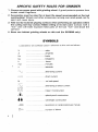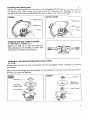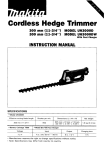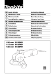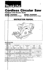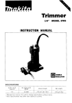
1
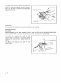
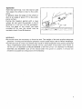
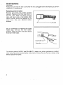
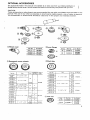
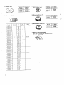
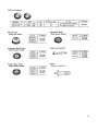
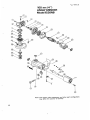
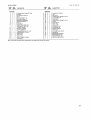
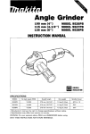
Angle 'Grinder
100 mm (4")
115 mm (4-1/2")
125 mm (5")
MODEL 9526NB
MODEL 9527NB
MODEL 9528NB
INSTRUCTION MANUAL
DOUBLE
INSU1AT I0 N
I
MODEL
No load speed (RPM)
Overall length
Net weight
Spindle thread
9526NB
10,000
256 mm (10")
1.4 kg 13.1 Ibs)
M10 x 1.5
9527NB
10,000
256 mm (10")
1.4 kg (3.1 Ibs)
5/8"
9528NB
10,000
256 mm (10")
1.4 kg (3.1 Ibs)
518"
GENERAL SAFETY RULES
(For All Tools)
WARNING! Read and understand all instructions. Failure
to follow all instructions listed below, may result in electric
shock, fire and/or serious personal injury.
SAVE THESE INSTRUCTIONS
READ ALL INSTRUCTIONS.
WORK AREA
1. Keep your work area clean and well lit. Cluttered benches and dark areas invite
accidents.
2. Do not operate power tools in explosive atmospheres, such as in the presence
of flammable liquids, gases, or dust. Power tools create sparks which may
ignite the dust or fumes.
3. Keep bystanders, children, and visitors away while operating a power tool.
Distractions can cause you to loose control.
ELECT R ICA L SAFETY
4. Double Insulated tools are equipped w i t h a polarized plug (one blade is wider
than the other.) This plug will fit in a polarized outlet only one way. If the
plug does not fit fully in the outlet, reverse the plug. If it still does not fit,
contact a qualified electrician t o install a polarized outlet. Do not change
the plug in any way. Double insulation El eliminates the need for the three
wire grounded power cord and grounded power supply system.
5.rAvoid body contact w i t h grounded surfaces such as pipes, radiators, ranges
and refrigerators. There is an increased risk of electric shock if your body is
grounded.
6. Don't expose power tools t o rain or wet conditions. Water entering a power
tool will increase the risk of electric shock.
7. Do not abuse the cord. Never use the cord t o carry the tools or pull the plug
from an outlet. Keep cord away from heat, oil, sharp edges or moving parts.
Replace damaged cords immediately. Damaged cords increase the risk of
electric shock.
8. When operating a power tool outside, use an outdoor extension cord marked
" W - A ' or "W." These cords are rated for outdoor use and reduce the risk
of electric shock.
PERSONAL SAFETY
9. Stay alert, watch what you are doing and use common sense when operating
a power tool. Do n o t use tool while tired or under the influence o f drugs,
alcohol, or medication. A moment of inattention while operating power tools
may result in serious personal injury.
IO. Dress properly. Do not wear loose clothing or jewelry. Contain long hair. Keep
your hair, clothing, and gloves away from moving parts. Loose clothes, jewelry
or long hair can be caught in moving parts.
11. Avoid accidental starting. Be sure switch is off before plugging in. Carrying
tools with your finger on the switch or plugging in tools that have the switch
on invites accidents.
12. Remove adjusting keys or switches before turning the tool on. A wrench or
a key that is left attached t o a rotating part of the tool may result in personal
injury.
13. Do not overreach. Keep proper footing and balance at all times. Proper footing
and balance enables better control of the tool in unexpected situations.
14. Use safety equipment. Always wear eye protection. Dust mask, non-skid
safety shoes, hard hat, or hearing protection must be used for appropriate
conditions.
TOOL USE AND CARE
15. Use clamps or other practical way t o secure and support the workpiece t o
a stable platform. Holding the work by hand or against your body is unstable
and may lead t o loss of control.
16. Do not force tool. Use the correct tool for your application. The correct tool
will do the job better and safer at the rate for which it is designed.
17. Do not use tool if switch does not turn it on or off. Any tool that cannot
be controlled with the switch is dangerous and must be repaired.
18. Disconnect the plug from the power source before making any adjustments,
changing accessories, or storing the tool. Such preventive safety measures
reduce the risk of starting the tool accidentally.
19. Store idle tools out of reach of children and other untrained persons. Tools
are dangerous in the hands of untrained users.
20. Maintain tools with care. Keep cutting tools sharp and clean. Properly
maintained tools, with sharp cutting edges are less likely to bind and are easier
t o control.
21. Check for misalignment or binding of moving parts, breakage of parts, and
any other condition that may affect the tool’s operation. If damaged, have
the tool serviced before using. Many accidents are caused by poorly maintained tools.
22. Use only accessories that are recommended by the manufacturer for your
model. Accessories that may be suitable for one tool, may become hazardous
when used on another tool.
SERVlCE
23. Tool service must be performed only by qualified repair personnel. Service
or maintenance performed by unqualified personnel could result in a risk of
injury.
24. When servicing a tool, use only identical replacement parts. Follow instructions in the Maintenance section of this manual. Use of unauthorized parts
or failure t o follow Maintenance Instructions may create a risk of electric shock
or injury.
3
SPECIFIC SAFETY RULES FOR GRINDER
1. Always use proper guard w i t h grinding wheel. A guard protects operator from
broken wheel fragments.
2. Accessories must be rated for at least the speed recommended o n the tool
warning label. Wheels and other accessories running over rated speed can fly
apart and cause injury.
3.Hold tool by insulated gripping surfaces when performing an operation where
the cutting tool may contact hidden wiring or its o w n cord. Contact with a
"live" wire will make exposed metal parts of the tool "live" and shock the
operator.
4. Never use hubbed grinding wheels on this tool (for 9526NB only).
SYMBOLS
Listed below are symbols used in reference to this tool and others
V
A
.................................
.................................
.................................
.................................
volts
amperes
hens
kilograms
hours
S
.................................
.................................
minutes
seconds
'L
.................................
alternating current
____
-
.................................
direct current
n.
.................................
no load speed
%
.................................
alternating or direct current
.................................
Class II Construction
Hz
kg
h
min
z
.................................
. splash-proof construction
Ab
.../min
@
................................
................................
........................
watertight construction
revolutions or reciprocation per minute
1 ........number of blows
I
Installing the wheel guard
Mount the wheel guard with the tab on the wheel guard band aligned with the notch on
the bearing box. Then rotate the wheel guard 180" clockwise (fo; 9526NB) or counterclockwise (for 9527NB and 9528NB). Be sure to tighten the screws securely.
9526NB
3527NB. 9528NB
,--Wheel
guard
I
Installing side grip (auxiliary handle)
For 9527NB and 9528NB only
Screw the side grip on the tool securely.
The side grip can be installed on either side
of the tool, whichever is convenient.
I
Installing or removing the depressed center wheel
CAUTION:
Always be sure that the tool is switched off and unplugged before installing or removing
the wheel.
Mount the inner flange onto the spindle. Fit the wheel on over the inner flange and screw
the lock nut onto the spindle.
9527NB
9528NB
Lock nut
-a
9526NB
?---
Lock nut
Depressed
center wheel
@-inner
flange
To tighten the lock nut, press the shaft lock
firmly so that the spindle cannot revolve,
then use the lock nut wrench and securely
tighten clockwise.
Lock nut wrench
\
WARN ING :
Only actuate the shaft lock when the spindle is not moving.
.
Switching action
CAUTION:
Before plugging in the tool, always check to see that the switch actuates properly and
returns to the “OFF” position when the rear of the switch lever is depressed.
To switch on, depress the rear of the
switch lever and push it forward. Then
depress the front of the switch lever to
lock it.
To shitch off, depress the rear of the
switch lever.
0
\
,-Switch
leve
Operation
Hold the tool firmly. Turn the tool on and
then apply the wheel or disc to the workpiece.
In general, keep the edge of the wheel or
disc at an angle of about 15” to the workpiece surface.
During the break-in period with a new
wheel, do not work the grinder in the B
direction or it will cut into the workpiece.
Once the edge of the wheel has been
rounded off by use, the wheel may be
worked in both A and 6 direction.
I
WARN ING:
It should never be necessary to force the tool. The weight of the tool applies adequate
pressure. Forcing and excessive pressure could cause injury due to wheel breakage.
*Continued use of a worn-out wheel may result in wheel explosion and serious personal
injury. Depressed center wheel should not be used after it has been worn down to
75 mm ( 3 ” ) in diameter for Model 9526NB or 90 mm (3-1/2”)in diameter for Models
9527NB and 9528NB. Use of the wheel after this point is unsafe; it should be
rendered unusable and disposed of immediately.
MAINTENANCE
CAUTION:
Always be sure that the tool is switched off and unplugged before attempting to perform
inspection or maintenance.
Replacing carbon brushes
Remove and check the carbon brushes
regularly. Replace when they wear down to
the limit mark. Keep the carbon brushes
clean and free to slip in the holders. Both
carbon brushes should be replaced at the
same time. Use only identical carbon
brushes.
--5%
Limit mark
Use a screwdriver to remove the brush
holder caps. Take out the worn carbon
brushes, insert the new ones and secure
the brush holder caps.
Brush holder cap
Screwdriver
l
\
To maintain product SAFETY and RELIABILITY, repairs, any other maintenance or adjustment should be performed by Makita Authorized or Factory Service Centers, always using
Makita replacement parts.
8
OPTIONAL ACCESSORIES
1
The accessories listed in this manual are available at an extra cost from your Makita distributor or
Makita factory service center. Service centers are listed on the warranty card packed with your tool.
CAUTION:
These accessories or attachments are recommended for use w i t h your Makita tool specified in this
manual. The use of any other accessories or attachments might present a risk of injury t o persons.
The accessories or attachments should be used only in the proper and intended manner.
@Wheel cover
@inner flange
224337-3
224332-3
@Multi-disc
@Depressed center wheels
741402-8
lRii1l.l
741402-9-1
741402-C
G,i,
Sire
Par1 No.
4..
741402 SAP
741405 2-1
Part No.
742038-OA
4" x 112" x 518''
1
4" x 114" x 518''
-
9526NB
C24R
4" x 3/16" x 518''
~
~~
4" x 114" x 518"
4" x 3/16" x 518''
Fi
24
5
1
36
741423 8
741423 0
4 112" x 114" x 718"
741424 8 1
5
-
1
9527N8
9526N8
742038 OC
80
742038-00
100
794332 2A
40
__
794332 28
794332-2C
1
741423 0 1
4 112" x 518" x 718"
794332-20
794331 4 0
9527N8
40
-
794331 4A
794331-48
794331 4C
60
R.r.
l
100
60
5" x 518"
718-
__
80
__
9528~8
100
@Lock nut
36
741424 8
741407 8
741427 8
For
Model
742038 08
741405 2P
7414268
Wheels
per pkg.
3116.,
941425 8
741402-8
9 ;: ;
24
5" x 114" x 718"
C24R
9528N8
9
@Lock nut 10-30
(For abrasive disc)
5Rubber pad
(@Wire cup brush 7 5
6,Abrasive discs
@)Wire bevel brush 85
or Model
(9)
9526NB
Wheel guard assembly
(For cut-off wheel) For Model 9526NB
Part No. 192476-6
@Cut-off wheel
Part No.
Size
Grit
Wheels per pkg.
724104-110
724107-510
4" x 3/32" x 5/8"
4" x 5/64" x 518"
36
10
10
Knot-Type
Wire cup brush
Part No.
46
I
For Model
For use
For masonry and concrete.
9526N8
For steel and cast iron.
Knotted Twist
Wire brush wheel
For Model
Lock nut wrench
Stringer Bead Twist
Wire brush wheel
Part No.
I
Part No.
For Model
Grip
Full Cable Twist
Wire brush wheel
Part No.
I
Part No. 152487-3
For Model
I
For Model
Aup.-19-’98
US
Note: The switch, noise suppressor and other part configurations
may differ from country to country.
12
MODEL 9526NB
Aug-l9--'96
DESCRIPTION
9
10
11
4
1
1
1
1
1
1
1
1
1
1
12
13
14
15
16
17
18
19
20
21
1
1
1
2
4
1
1
1
\
1
6
7
8
-
-
F
IOMztD DESCAlPTlON
MACHINE
MACHINE
1
2
3
4
5
US
Tapping Screw Flange PF 5x30
P," cap
Comprermon Spring 8
PI" 4
Retaining Ring S - 6
Spiral Bevel Gear 10
Bell Bearing 600000W
Gear Housing Cover
Fan 57
Baffle Plate
ARMATURE ARMATURE
IWith Item 9. 12 & 131
Insulation Washer
Ball Bearing 60622
FIELD ASSEMBLY
Tapping Screw Bind PT 3x10
Tapping Screw CT 4x16
Swktch Knob
Name Rate
Switch Lever
~ o t onousing
l
Complete
Cord Guard
Comprarrlon Sprmg 4
Cord
Rear Cover
Tappmg Screw Flange PF 4x18
Termma1 Block 1P
Siram Relief
Tapping Screw Flange PF 4x18
Switch
Carbon Brush
Holder Cap
Makita Label
Lock Nul 10-30
Inner Flange 30
Spmdle Complete
Wheel Cover
Pan Head Screw M S x l 6
Bearing Box
Bell Bearing 62OlODW
Retaining Ring R - 3 2
Spiral Bevel Gear 36
ear nousmg compiele
Note: The switch and ofher part specifications may differ lrom country 10 country.
13
Aug.-19--'96
US
ANGLE GRINDER
115 mm (4-1/2") Model 9527NB
125 mm (5")
Model 9528NB
Note: The switch, noise suppressor and other part configurations
may differ from country to country.
14
MODEL 9527NB. 9528NB
'i\M
G2D
DESCRIPTION
MACHINE
1
2
4
5
6
7
8
9
10
11
4
1
1
1
1
1
1
1
1
1
1
12
13
14
15
16
17
18
19
20
21
1
1
1
2
4
1
1
1
1
1
3
-
Aug.-19-'96
E
'M AtD
DESCRIPTION
MACHINE
Tapping Screw Flange PF 5x30
PI" Cap
Compression Spring 8
P," 4
Retammg Ring S - 6
Spiral Bevel Gear 10
Ball Bearing 6WODDW
G~~~ nousmg cover
Fan 57
Baflle Plate
ARMATURE ARMATURE
IWtth Item 9. 12 & 131
lnsulall~nWasher
Ball Bearing 60622
FIELD ASSEMBLY
Tapping Screw Bind PT 3 x 1 0
Tapping Screw CT 4x16
Switch Knob
Name Plats
Switch Laver
Motor nouslng Complete
Cord Guard
22
23
24
25
26
27
28
29
30
31
32
33
34
35
36
37
38
39
40
41
42
-
Note: The switch and other p a n specifications may differ from country to country
1
1
1
2
1
1
2
1
2
2
1
1
1
1
1
1
1
1
1
1
1
Compression Spring 4
Cord
Rear Cover
Tapping Screw Flange PF 4x18
Terminal Block 1P
Strain Relief
Tapping Screw Flange PF 4x 18
Switch
Carbon Brush
Holder Cap
Mahila Lsbel
Lock Nut 14-46
Inner Flange 42
Spindle Complete
Wheel Cover
Pan Head Screw M S x l 6
Bearing Box
Ball Beanng 620lDDW
Reiammg Ring R-32
Spiral Bevel Gear 36
Gear Housing Complete
US
MAKFA LIMITED ONE YEAR WARRANTY
Warranty Policy
Every Makita tool is thorou ly inspected and tested before leaving the factory. It is warranted to
be free of defects from workanship and materials for the period of ONE YEAR from the date of
original purchase. Should any trouble develop during this one-year period, return the COMPLETE
tool, freight prepaid, to one of Makita's Factory or Authorized Service Centers. If inspection shows
the trouble is caused by defective workmanship or material, Makita will repair (or at our option,
replace) without charge.
This Warranty does not apply where:
a repairs have been made or attempted by others:
a repairs are required because of normal wear and tear:
a The tool has been abused, misused or improperly maintained ;
a alterations have been made to the tool.
IN NO EVENT SHALL MAKITA BE LIABLE FOR ANY INDIRECT, INCIDENTAL OR CONSEQUENTIAL DAMAGES FROM THE SALE OR USE OF THE PRODUCT. THIS DISCLAIMER
APPLIES BOTH DURING AND AFTER THE TERM OF THIS WARRANTY.
MAKITA DISCLAIMS LIABILITY FOR ANY IMPLIED WARRANTIES, INCLUDING IMPLIED
WARRANTIES O F "MERCHANTABILITY" AND "FITNESS FOR A SPECIFIC PURPOSE,"
AFTER THE ONE-YEAR TERM OF THIS WARRANTY.
This Warranty gives you specific legal rights, and you may also have other rights which vary from
state to state. Some states do not allow the exclusion or limitation of incidental or consequential
damages, so the above limitation or exclusion may not apply to you. Some states do not allow
limitation on how long an implied warranty lasts, so the above Limitation may not apply to you.
Makita Corporation of America
2650 Buford Hwy., Buford, GA 30518
MCA' 11-96
884064-062
PRINTED IN USA
1997-01-4D