1
MIDI TUBE GUITAR PRE-AMP
OWNER’S MANUAL MP-2
(version 1)
Originally written by ADA SIGNAL PROCESSORS, INC. Scanned and edited by Jur at 14 june 2002. Original
ADA logo edited and rendered by Barend Onneweer of Raamw3rk.) The version of this manual is copyrighted and
may not be sold or placed on a website without permission of the editor.
Release No.1 for http://www.ada-mp1.com
Contents
Chapter 1 Introduction
About This Manual
MP-2Features
Chapter 2 Quick Start.
Chapter 3 Getting Started
Unpacking and Installation
Controls and Connectors
Connecting the MP-2
Audio
MIDI
Chapter 4 Tutorial.
Basics of the MP-2
Programs
MP-2Modes
MP-2Display
Powering Up
Play Mode
Recalling Programs
Program Edit mode
Editing Basics
Selecting and Editing Parameters
Comparing Edited Programs to Stored Versions
Naming User Programs
Storing Programs
Setting Input and Output Levels
Using the Stereo Effects Loop
System Edit Mode
Copying Programs
MIDI Parameters
Real-Time MIDI (RTM)
Making RTM Assignments in Quick Mode
The Next Step
Chapter 5 Reference
Play Mode
Using Real-Time MIDI in Play Mode
Program Edit Mode
Storing, Abandoning, and Resuming Edits
TubeVoicing
Drive & Master Level
Compressor
Tone Controls
Graphic EQ
Wah Filter
Tremolo
Noise Reduction
Stereo Chorus
Stereo Effects Loop
Program Title
Real-Time MIDI (RTM)
Compare
System Edit Mode
Page: 2
MIDI Function Menu
Copy Presets to User
Copy Single Programs
Swap Programs
Panel Mode
Restore System Defaults
Memory Protect
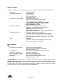
Appendix A Specifications
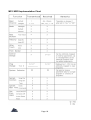
MP-2 MIDI Implementation Chart
Appendix B MIDI and the MP-2
Appendix C Troubleshooting
Troubleshooting Tips
Audio Problems
MIDI Problems
Page: 3
Page: 4
Chapter 1
Introduction
This chapter describes this manual and lists the MP-2's features.
Thank you for purchasing the ADA MP-2 MIDI Programmable Tube Preamp. The MP-2 is the
latest generation of ADA's programmable tube preamp technology, and contains more gain,
processing options, MIDI functions, and professional features than any previous product.
IMPORTANT: Please take the time to fill out and return the enclosed warranty card so that
we may provide you with information on future software updates.
This manual provides complete information on the MP-2's features and the procedures for
using them. Despite its easy, intuitive operation, making full use of a sophisticated
programmable device like the MP-2 requires spending some time studying the manual. If the
manual appears somewhat daunting, it is only because of the sheer volume of the MP-2's
features, but you will find the time studying the manual well spent as you discover the extent
of the MP-2's considerable facilities. Further, the factory default values and Programs can
always be reloaded if you "screw up" too badly, so you should have no fear of experimenting
when first learning the MP-2.
About This Manual
The body of the manual is divided into five chapters:
Introduction:
Quick start:
Getting Started:
Tutorial:
Reference:
is this chapter that describes the manual and lists the MP-2's features.
gives a brief procedure for immediate use of the MP-2.If you need to
jump right into using the MP-2 without first reading the entire manual,
turn to the Quick Start chapter which immediately follows this
introduction.
explains all of the MP-2's controls and connections.
gives a guided tour of the MP-2's basic functions in a series of lessons.
Read this chapter to familiarize yourself with operating the MP-2. The
first time a new term is introduced in the Tutorial it appears in bold and
underline: new term.
contains detailed explanations of every MP-2 function. Use this
chapter when you are trying to get information on a specific feature.
There are also a number of Appendixes. found at the end of the manual, which give helpful
information and further explanations on a number of topics relating to using the MP-2.
NOTE: Information crucial to understanding the MP-2 is always encased in a box such as
this one. Always read this information.
Page: 5
MP-2 Features
Complete digital control of an all-analog signal path.
128 User programs plus 39 factory Preset programs.
Two low-noise 12AX7A tubes with 10 tube voicing settings and overdrive.
Onboard compressor for maximum sustain and funk squeeze.
Four-band tone controls for basic tone shaping.
Nine-band graphic equalizer for detailed tone adjustments.
Powerful effects, including wah-wah, tremolo, and stereo chorus.
Noise reduction circuitry to reduce unwanted hum and noise at high gain
settings.
Stereo effects loop with programmable mix control. Side-chain design keeps
dry signal within MP-2, preserving dynamics and signal-to-noise ratio.
Speaker emulation circuit and room compensation equalization.
Cabinet-emulated, balanced XLR outputs with ground lift, as well as
unbalanced 1/4" phone outputs for recording.
Independent unbalanced 1/4" phone outputs for stage use.
Front and rear panel 1/4" phone inputs for easy access.
Complete MIDI implementation, including Real-Time MIDI for changing
parameters "on the fly."
Optional MIDI Controller Pedal Pack provides instant access to any program
for fast on-stage control, plus real-time MIDI continuous control.
Page: 6
Chapter 2
Quick Start
This chapter gives a brief procedure for immediate use of the MP-2.
So you can't wait to plug in your new MP-2 and get some sounds. That's perfectly
understandable, so here is the way to jump right in and get started. Once you get that far,
you'll probably want to explore further.
The Tutorial in chapter 4 takes you on a guided tour through the MP-2, showing the most
important features and giving you an idea how to work with the unit. As you become more
experienced with the MP-2 you will probably need to use the Reference chapter to find out
details about specific features.
1) Be sure all equipment is turned off.
2) Connect the MP-2 to AC power.
3) Connect your instrument to the MP-2's Input.
4) Connect the MP-2's Stage Outputs to a power amplifier and speaker system or to the
line input of a mixing console.
NOTE: If an instrument amplifier is the only amplifier available, plug into its Effects
Return, if there is one. If not, plug into the clean channel and keep the input volume low.
5) Be sure the Output Level control on the left of the front panel is turned all the way
down (set to "Min"), the Room EQ control is set to Normal (12 o'clock), and the
volume on the amplifier is turned all the way down.
6) Turn on the MP-2, then turn on the amplifier. When the MP-2 is first turned on, it will
take a few moments for the tubes to warm up. After warming up, the MP-2 will enter
Play mode running User program 1.
7) Raise the amplifier volume to a moderate level, then slowly raise the Output Level
control and play. Adjust the Output Level control to a comfortable listening level.
8) Use the Up and Down arrow keys to recall programs. The first 39 User programs are
the same as the factory Preset programs.
Page: 7
Chapter 3
Getting Started
This chapter explains all of the MP-2's controls and connections.
Unpacking and Installation
IMPORTANT: The MP-2 is designed to operate only at the voltage printed on the
back panel. It is not possible to change over or adapt the MP-2 to operate at any
other voltage.
Please use an appropriate external voltage converter when attempting to operate the
MP-2 in a country with a different AC line voltage.
Rack-mounting the MP-2
The MP-2 is designed to mount in a single rack-unit of (lu) of space in any standard 19"
equipment rack. Be sure that it is securely mounted using four standard (10-32) rackmount
screws.
About Tubes and the MP-2
The incomparable sound of tube amplification comes with the need for a small amount of
simple maintenance to accommodate the nature of tubes, which are somewhat fussier and
more delicate than the solid-state electronics used in the rest of the MP-2.
NOTE: To preserve tube life, allow time for the tubes to cool after shutting down the MP-2
before moving. Tube elements are more fragile when hot.
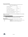
Tubes have a limited life span; it is recommended that the MP-2's tubes be replaced about
once every year, or if they show signs of wearing out. Some signs of degrading tube life are:
• "Ringing", squealing or feedback
• Microphonic effects (tapping on the MP-2 causes audible thumps)
Replace the MP-2's tubes only with high-quality, low-noise 12AX7A-7025 tubes. If desired,
these can be purchased from ADA (ADA part # 220020).
Page: 8
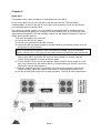
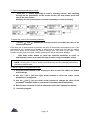
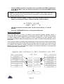
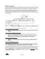
Controls and connectors
Page: 9
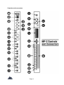
Front Panel (L to R)
[1] Input
Accepts unbalanced 1/4" phone instrument inputs. Maximum
level: +12.2 dBV (3.4 volts RMS). This input overrides the rear
panel input.
[2] Output Level control
Final adjustment of output level. Follows all software level
controls.
[3] Output Clip LED
Indicates overload of output stage.
[4] Room EQ control
Applies tone shaping to compensate for the acoustic effects of
different performing venues. Normal setting is straight up (12
o'clock).
[5] Comp Thresh LED
When Compressor is switched in, indicates that the signal is
exceeding the compressor threshold.
[6] Signal LEDs
When glowing green: indicates the signal present in that
section is 30 dB below clip level. When glowing red: indicates
signal present in that section in 3 dB below clip level.
NOTE: The Signal LEDs will illuminate regardless of that section's Status (i.e. switched
in or out.)
[7] Character display
2-rows by 16-characters LCD. Shows status and error
messages. Play mode: shows bank and number of current
program. In Controller panel mode, shows mapping of MIDI
program change number to MP-2 User program number.
Program and System Edit modes: shows parameter editing
information.
8] Arrow buttons
Left/Right arrows: used to move cursor be tween parameters
and screens in Program and System Edit modes.
Up (YesVDown (No) arrows: used to adjust the value of the
currently selected parameter, execute a function, or answer a
query.
[9] Bank Select buttons
In Play mode, increases (Bank Up) or decreases (Bank Down)
the bank number from which a program may be called.
[10] Number buttons (0-9)
In Play mode, selects which program in a bank will be recalled.
[11] Preset/User button
In Play mode, switches between factory Preset program banks
and User program banks.
[12] Program Edit button
Enters and exits Program Edit mode. Initiates Store function
when exiting Program Edit mode. LED is lit when in Program
Edit mode.
[13] System Edit button
Enters and exits System Edit mode. LED is lit when in System
Edit mode.
Page: 10
[14] Edit functions
When in Program Edit mode, the Bank Select, Number, and
Preset/User buttons select the parameter sections indicated in
the gray field above them.
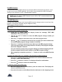
Rear Panel (R to L)
[1] Input
Accepts unbalanced 1/4" phone instrument
inputs. Maximum level: +12.2 dBV (3.4 volts RMS). Plugging
into the front panel input overrides this input.
[2] Effects Loop A
Send
Level Switch
Return (Insert)
Carries channel A of signal following Stereo Chorus. Must be
switched on in software to be active.
This switch sets both the level from the Send and expected at
the Return for Effects Loop A.
Carries return from external effects units.Must be switched on in
software to be active. Mix is adjustable in software.
[3] Effects Loop B
Send
Level Switch
Return (Insert)
[4] Stage Outputs
Carries channel B of signal following Stereo Chorus. Must be
switched on in software to be active.
This switch sets both the level from the Send and expected at
the Return for Effects Loop B.
Carries return from external effects units. Must be switched on
in software to be active. Mix is adjustable in software.
Stereo unbalanced 1/4" phone outputs which do not pass
through Cabinet Emulator circuitry. Intended for use as main
outputs for connection to a sound system. Maximum output
level:+17.1dBV
Recording Outputs
[5] Speaker Cabinet Emul. switch Selects emulation for the Recording Outputs only of either a 212" cabinet or a 4-12" cabinet.
[6] Unbalanced Outputs
Stereo unbalanced 1/4" phone outputs which pass through
Cabinet Emulator circuitry. Maximum output level: +17.1 dBV
[7] XLR Level switch (Line/Mic) This switch sets the output level from the balanced (XLR)
outputs.
[8] Balanced Outputs
Stereo balanced XLR outputs which pass through Cabinet
Emulator circuitry. The signal from these outputs is identical to
the Unbalanced Outputs. Maximum output level is determined
by position of XLR Level switch: +12 dBV (Line), -16 dBV (Mic).
[9] Pin 1 (Ground) Lift switch Used to eliminate hum from grounding problems when
connecting to mixing consoles, etc. In the GND (normal)
Page: 11
position, pin 1 of the balanced outputs is connected to circuit
ground. In the LIFT position, pin 1 of the balanced outputs is
disconnected from circuit ground.
MIDI Connectors
[10] Phantom Power
Input which accepts AC power adapters for ADA MIDI
footswitches and connects to pins 6 and 7 of the MP-2's MIDI
In jack. When used in conjunction with the proper 7-pin DIN
phantom power cable, allows ADA MIDI footswitches to be
remotely powered.
[11] MIDI In
When connected with a standard MIDI cable, receives data
from a MIDI controller. By plugging an ADA AC power adapter
to the Phantom Power jack and using a 7-pin DIN phantom
power cable from this jack to an ADA MIDI footswitch, power is
supplied from this jack to the controller through the MIDI cable.
[12] MIDI Out
Carries MIDI data output by the MP-2.
[13] MIDI Thru
Carries an exact copy of data received at MIDI In.
[14] AC power cord
Plugs into a normal wall outlet.
[15] Fuse
Accepts a .5 A (for 117V US models) or .25 A (for 230V export
models) Slo-Blo type fuse.
[16] Power Switch
Switches MP-2 on and off.
Page: 12
Page: 13
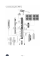
Audio
Input
•
Connect instrument's unbalanced 1/4" phone output to the MP-2's front or rear panel
input jack. If you are using a tuner for your instrument, plug the instrument into the
tuner and connect the tuner's output to the MP-2's input.
NOTE: The MP-2 's front panel input jack overrides the rear panel input. Signals going to
the rear panel input will be disconnected if an input is connected to the front input jack.
Output
• Connect the Stage Outputs to the power amplifier's unbalanced 1/4" phone input.
• Connect the unbalanced Recording Outputs to the mixing console or recorder's
unbalanced 1/4" phone Line inputs.
OR
• Connect the balanced Recording Outputs to the mixing console or recorder's balanced
XLR Mic or Line inputs. Use the XLR Level switch on the rear panel to set optimum
level range.
NOTE:
1) The MP-2 is capable of output levels high enough to overload the input of most
guitar or instrument amplifiers and many other devices. Adjust the front panel
Output Level control to avoid unwanted overload distortion.
2) The MP-2 's outputs are independently buffered and so may all be used
simultaneously, if so desired.
3) For mono operation any single output can be used.
Effects Loops
•
Connect Effects Loop A and B Sends to the unbalanced 1/4" phone inputs of any
reverb, effects device, or other signal processor. Use either Effects Loop Send for
devices that have only a single (mono) input. The Sends and Returns are only active
when Effects Loop Status is set to "On".
• Connect Effects Loop A and B Returns to the unbalanced 1/4" phone outputs of the
reverb, effects device, or other signal processor. If the device has only one output,
use a Y-cable to split the signal and connect it to both Returns to have effects in both
channels. Set output mix of the signal processor to 100% "wet".
• Use the Effects Loop Level switches (A and B) to set the Send and Return levels to
the optimum match with the external device.
NOTE: Status for the Effects Loop must be set to "On" and the Wet Mix parameter set
greater than 0%for the Returns to be heard.
Page: 14
MIDI
The MP-2 is capable of responding to MIDI program change and continuous controller
messages. It is recommended that a MIDI controller capable of accepting at least one
footpedal (to be assigned in System Edit mode to Stereo Volume Controller) and one
footswitch (to be assigned in System Edit mode to control the Tuner Mute function) be used,
such as the ADA MXC. See the System Edit portion starting on page 58 of the Reference
chapter for a complete explanation of programming the Stereo Volume Controller and Tuner
Mute functions.
•
Connect MIDI In to MIDI Out of ADA MXC or other MIDI controller. Be sure that
all required footpedals, footswitches, or other control devices are properly
connected to the MXC or other MIDI controller.
•
Connect MIDI Out to MIDI In of other MIDI devices you wish to control from the
MP-2 front panel.
• Connect MIDI Thru to MIDI In of other devices you wish to receive the same data
from your MIDI controller which the MP-2 receives, such as MIDI-controlled
effects processors.
Sending and Receiving Libraries and Programs
The MP-2 can send or receive one or all of its User programs to another MP-2 or a personal
computer running an appropriate librarian or sequencing program.This information is sent
over MIDI as System Exclusive Data.
Connections for sending/receiving a library or program to/from another MP-2:
•
Connect MIDI Out from the MP-2 that is sending the data to MIDI In of the MP-2
that is receiving.
Connections for sending a library or program to a personal computer:
•
Connect the MP-2's MIDI Out to MIDI In of the computer's MIDI interface.
Connections for receiving a library or program from a personal computer:
•
Connect the MP-2's MIDI In to MIDI Out of the computer's MIDI interface.
NOTE: Some librarian programs may require two-way communication with the MP-2. In
this case it is necessary to connect both the MP-2 's MIDI Out to the computer's MIDI
In and the computer's MIDI Out to the MP-2 's MIDI In.
Phantom Power Input
The Phantom Power jack connects directly to pins 6 and 7 of the MIDI In jack and, when the
proper 7-pin DIN cable is used in place of a standard MIDI cable, provides a method of
remotely powering an ADA MXC MIDI foot control system. A 25-foot 7-pin DIN Phantom
Power cable is available from ADA (Part #401016)
•
Plug the power adapter for the MXC MIDI foot controller into an AC outlet.
•
Plug the end of the adapter that normally connects to the MXC into the
Phantom Power jack.
•
Connect a 7-pin Phantom Power cable from MIDI Out of the MXC to MIDI In of
the MP-2.
Page: 15
Chapter 4
Tutorial
This chapter gives a guided tour of the MP-2's basic functions in a series of lessons. Read
this chapter to familiarize yourself with operating the MP-2.
This chapter will introduce you to the basics of using the MP-2 and lead you step by step
through the most important functions. Once you have completed the Tutorial, you will be able
to create and store your own programs, as well as use the factory Preset programs, and use
MIDI to control the MP-2.
But the MP-2 has more features than this Tutorial will touch on. The Reference chapter gives
detailed descriptions of every parameter and will answer any questions you may have left
after completing the Tutorial.
Basics of the MP-2
Programs
The MP-2 has two different kinds of settings that can be adjusted and stored: those that
affect individual sounds, and those that affect the whole MP-2 and don't change when a
sound is changed.
All of the settings that define an individual sound are stored collectively as a program.
Programs can be recalled from the front panel or by MIDI messages from a MIDI controller
such as the ADA MXC. Programs are edited in Program Edit mode. Settings that affect the
whole MP-2 are not stored as part of a program, but as global parameters and edited in
System Edit mode. Global parameters, most notably the MIDI functions in System Edit, are
in effect all the time, regardless of what program is running.
NOTE: The Stereo Volume Controller and Tuner Mute are both global parameters.
Some confusion or problems may arise if this idea is not fully understood and kept in
mind. For a complete explanation of global settings, see the System Edit portion of the
Reference chapter.
There are two kinds of programs: Preset and User. Preset programs were created by ADA
and the artists we work with. They can be recalled, played, and even edited, but a location
containing a Preset program cannot be written to. There are 39 Presets in the MP-2, and a
list of these is found in an Appendix at the end of the manual.
User programs are those created by you, the user, usually by modifying Presets or User
programs previously created. There are 128 User programs, and these can be both recalled
and written (stored) to. If a Preset program is recalled and edited, it can only be stored as a
User program.
User programs can be transferred over MIDI from one MP-2 to another, or from an MP-2 to a
personal computer running librarian software. This means that, when all the User programs
are filled, they can be dumped, or "off-loaded" to the computer through MIDI System
Exclusive messages to prevent having to write over User programs in order to store new
ones.
Page: 16
MP-2 Modes
The MP-2 has three operating modes: Play, Program Edit and System Edit.
In Play mode, programs may be recalled for performance from the front panel or through
MIDI. The MP-2 is in Play mode whenever it is in neither Program Edit nor System Edit
mode. When neither the LEDs in the PRGM EDIT nor SYSTEM EDIT buttons are lit, the MP2 is in Play mode.
In Program Edit mode, all of the settings (also called parameters) contained in a program
can be adjusted. The MP-2 is in Program Edit mode when the LED in the PRGM EDIT button
is lit. (See page 42 for Reference information on Program Edit mode.)
In System Edit, settings that affect the entire MP-2 and are not stored as part of a program
are adjusted. There is only one location for these settings, so they are not stored and
recalled as programs are. System Edit mode also contains utilities that allow copying and
swapping of programs between locations and other useful functions. The MP-2 is in System
Edit mode when the LED in the SYSTEM EDIT button is lit. (See page 58 for Reference information on System Edit mode.)
MP-2 Display
The MP-2 conveys messages, questions, and parameter information through the display.
Play Mode
In Play mode, the display shows whether the MP-2 is running a User or Preset program, the
program bank and number, and its name.
Program Edit Mode
In Program Edit mode, the display shows one or more parameters in the currently selected
section along with their values. The cursor indicates which parameter is currently selected
for editing. Arrows in the upper left and/or lower right corners indicate that there are other
parameter screens in that section.Parameter screens are explained on page 24 in the Editing
Basics discussion.
Page: 17
System Edit Mode
The System Edit mode display is essentially the same as the Program Edit mode display, but
in many cases the parameters take the form of a question, asking if you wish to execute the
named System function. These questions are answered by pressing the "A" ("Yes") or "v"
("No") button, indicated by an arrow pointing up.These up-facing arrows also sometimes
indicate submenus or steps in a procedure.
Powering Up
•
After connecting the MP-2 as described in the Getting Started chapter, turn on
the power switch on the rear panel. Be sure the Output Level control is turned
all the way down and the Room EQ control is set to Normal.
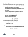
When switched on, the MP-2 will first display a screen with ADA's name, then a screen
identifying the unit as an MP-2 and showing the software version installed:
The MP-2 is a tube preamp, and tubes take a few moments to warm up when they are first
switched on. During this period, the MP-2's display will show this message:
•
Slowly raise the Output Level control until the volume is comfortable. Be careful
not to overload the input of the amplifier or mixer into which the MP-2 is
plugged.
Page: 18
Play Mode
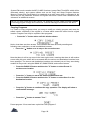
After the tubes have warmed up, the display will say something like this:
Notice that the LEDs in the PRGM EDIT and SYSTEM EDIT buttons are both unlit. The MP-2
is now in Play mode. The top line indicates that the MP-2 is currently running User program
1, while the bottom line is the program's name.
Recalling Programs
Recalling programs in Play mode is as simple as could be: To step through
programs:
• Press the "∧" and "∨" (up and down arrow) buttons to increment and decrement
the program number. When the arrow button is released, the new program is recalled.
•
Try pressing the " ∧ " button a few times and watch the User program number
increase.
Play through a few of the User programs to see that the programs are actually changing.
•
Press the "∨" button until you reach User program 1, then press it one more
time.
Note that the MP-2 "wraps around" to the highest number, User 128.
Page: 19
Right now, the first 39 User programs contain the same settings as the 39 Preset programs.
Of course, these User programs can be replaced at any time with modified versions, or other
programs that have been copied to them or swapped with them. The Preset programs can
be altered while they are running, but the Preset program locations cannot be stored into, so
they always remain unchanged.
To switch between User and Preset Programs
•
Press the PRESET/USER button on the right side of the front panel.
The MP-2 switches to Preset program 1.
•
Use the "∧" and "∨" buttons to step through the Preset programs.
Program Edit mode
•
Press the PRGM EDIT button to enter Program Edit mode.
The LED in the button will go on and the display will say:
Editing Basics
When an instrument is plugged into the MP-2, its signal passes through a number of different
sections, each of which has a different function. The sections are indicated in the gray field
above the Bank Select, Number, and Preset/User buttons.
Each section has several parameters that can be adjusted. A program is simply a stored
complete set of all the parameters in all the sections.The cursor always indicates which
parameter is currently selected for editing.
Some sections have more parameters than can fit in the display at one time. In that case,
there may be more than one screen of parameters. The presence of additional screens is
indicated by an arrow symbol in the lower right corner of the display (meaning there is one or
more following screens) or the upper left corner (meaning there is one or more preceding
screens).
To select a parameter for editing:
•
Use the "<" and ">" buttons (left and right arrow) to move the cursor from
parameter to parameter.
The parameter that is currently selected for editing is always indicated by the cursor, which
is an arrow symbol (->) found between the parameter name and its value.
Page: 20
To move between parameter screens:
•
Press the ">" button repeatedly to reach a following screen; after stepping
through all the parameters on the current screen, the next button press will
step to the next screen.
Similarly, the left arrow button is pressed repeatedly to reach preceding
screens.
To adjust the value of the selected parameter:
Use the "∧" and "∨" buttons (up and down arrow) to modify the value of the
selected parameter.
•
Each time one of these buttons is pressed, the value is increased or decreased by one. If the
parameter is not a number but a toggle, or switch-type of setting that only has two values,
the up and down arrow buttons are used to change from one value to the other. These
buttons are also used to answer Yes/No questions the MP-2 sometimes displays.
•
Hold down either button to cause the selected parameter to scroll, or
automatically count, up or down through its entire range of available values.
NOTE: Pressing the "A" and "v" buttons simultaneously sets the selected parameter to
the factory default value.
To edit a program in Program Edit mode:
1) Press the Select button of the section you wish to edit. The LED in the button
will illuminate
2) Use the < and > (left and right arrow) buttons to move the cursor to the
parameter to be adjusted.
3) Use the ∧ and ∨ (up and down arrow) buttons to change the value of the
parameter. Changes made to a parameter are always heard immediately.
4) Repeat steps 1 through 3 until all parameters have been adjusted as desired.
5)
Store the program.
Page: 21
Selecting and Editing Parameters
• Press the Tube Voicing button to select the Tube Voicing section. The button's LED
will light up and the display will show:
There are no arrows in the upper left or lower right corner; the Tube Voicing section has
only one screen of parameters.
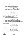
• Press the "v" button twice to change the Tube Voicing value. The display shows:
• Press the Drive & Master Level button to select the Drive & Master Level section.
Now the display shows:
• Press the ">" button once to move the cursor to the Overdrive parameter.
• Press and hold the "v" button. The Overdrive value will count down. Set its value to
75.
Because the value will scroll quickly, it is difficult to stop at precisely the right value. Lift your
finger from the arrow button when the value is close to the desired setting, then use
individual button presses to step it to the exact desired value.
•
Press the Stereo Chorus button to select the Stereo Chorus section.
Notice the arrow indicating a following screen:
•
Press the ">" button once to step to the next screen of parameters.
•
Press the ">" button one more time to move the cursor to the Rate parameter.
•
Press the "∧" button three times to increase the Rate to 0.5 Hz.
Page: 22
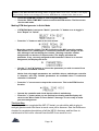
Editing the Graphic EQ
The Graphic EQ display is a little different from most of the other sections. Instead of using
letters or numbers to show the value of a parameter, the Graphic EQ gives a simple visual
plot that clearly indicates the whole equalization curve.
•
Press the Graphic EQ button to select the Graphic EQ section.
The horizontal lines represent the boost/cut settings of each of the nine bands of the Graphic
EQ, with the band currently selected having a double line (in this case, on the far left).
(Bands set to 0 dB of boost/cut also have double lines, but the lines are more widely spaced
and easily distinguished from the selected band.) On the right side of the display, the
currently selected band is shown on top, and the amount of boost/cut applied on the bottom.
The "<" and" >" buttons move the cursor to the band to be adjusted, and the "∧" and "v"
buttons change the amount of boost/cut applied at that band in two dB steps up to ±12 db.
•
Press the ">" button until the upper right corner of the display shows "2.2KHz."
•
Press the "∧" button three times to change the amount of boost/ cut to +2 dB.
Comparing Edited Programs to Stored Versions
When editing a program it is desirable to be able to compare the current version with the
original, stored version without leaving the edit mode.
•
Press the COMPARE button to engage the Compare function. The display will
tell you that you are now listening to the stored version:
• Press the COMPARE button again and the MP-2 toggles back to the edited
version:
Each press of the button causes the MP-2 to toggle.
Page: 23
Naming User Programs
At this point, it would be good to give this program a different name to distinguish it from the
Preset it started out as.
•
Press the "PROGRAM TITLE" button to select the Program Title section.
Editing in this section can be thought of in the same way as in other sections if you consider
each character in the name as a parameter, the underline at the bottom as the cursor, and
the choice of letters, numbers, and symbols as the available values.
The "<" and ">" buttons move the cursor from character to character in the name, while the
"∧" and "v" buttons choose the desired letter, number, or symbol for the selected
character.Pressing the "∧" and "v" buttons at the same time clears the entire name.
•
Press the ">" button until the underline is in the last space in the right corner.
•
Hold the "∧" button down and scroll through until the number "2" comes up.
(The numbers follow the lower case letters, which are after the upper case
letters.)
Storing Programs
Since enough changes have been made that it would be annoying to lose them, our modified
and renamed program should now be stored before continuing. The MP-2 asks if you wish to
store whenever you attempt to exit Program Edit mode after having altered any of a
program's parameters.
•
Press the PRGM EDIT button to exit Program Edit mode. The display will briefly
show:
then change to:
The User program value shown is the last User program used by the MP-2. Note that only
User programs are available for storing.
To store a program in the User program shown:
• Press the "∧" button to answer "Yes."
To select a different User program in which to store a program:
•
Use the BANK UP, BANK DOWN, and number buttons in the same fashion as
recalling a program in Play mode to select the desired User program.
Page: 24
•
Press the "∧" button to answer "Yes."
After answering "Yes," the MP-2 will ask for confirmation:
•
Press the "∧" button again to answer "Yes" and complete the store.
To abort the store process and return to editing:
•
Press the PRGM EDIT button to reenter Program Edit mode. Select a section
and continue editing. All parameters will be as they were when you first
attempted to exit Program Edit mode.
To abort the store process and discard the changes to the program:
•
Press the "v" button when the "Store in User Program 128? Y/ N" message
appears to answer "No."
•
Press the "∧" button to answer "Yes" when the above message appears.
After the above message appears, the MP-2 will be in Play mode.
Pressing the "v" button to answer "No" to the abandon message will return you to the store
message.
Memory Protection
The MP-2 has a memory protection feature in the System Edit mode (discussed later) which
prevents any User program from being written to. The factory default setting for this feature is
"Off," however, should memory protection be turned on, it adds an additional confirmation
message to the store process. After responding "Yes" to the confirmation ("Are You Sure?")
message, the MP-2, when Memory Protect is set to "On," will briefly show this message:
Page: 25
then offer the chance to turn off memory protection:
Press the "∧" button to answer '' Yes'' and turn off memory protection. The display will
return to the confirmation message, only now it will allow the store to be completed.
•
NOTE: Once Memory Protect has been disabled in this fashion, it is no longer
active unless reenabled in the System Edit mode.
•
Pressing the "v" button to answer "No" to the disable message returns you to the
abandon message.
Setting Input and Output Levels
The MP-2 contains a number of level controls that serve different purposes. Getting the best
sound requires that the MP-2's input and output levels be properly adjusted. Here are a few
hints:
1) Modifying an existing preset is the best way to optimize the signal-to-noise
ratio.
2) Use the signal indicators on the front panel to insure that the MP-2 is being
driven with an adequate amount of signal, and not overloaded undesirably. Try
to set signal level so that the LEDs are lighting green on a regular basis.
Remember that too little signal degrades the signal-to-noise ratio.
3)
Avoid clipping the MP-2's internal circuitry; watch for signal LEDs that are
frequently lighting red or for frequent lighting of the Clip LED. Two common
causes of internal overload are large amounts of boost in the EQ sections or
excessive Gain in the Compressor section.
4) The Drive parameter in the Drive and Master Level section controls the amount
of gain applied by the tube preamp. High gain Tube Voicings also have an
Overdrive parameter in this section for even more gain.
5)
The Master parameter in the Drive and Master Level section controls the
amount of signal fed from the tube preamp to the rest of the MP-2. It is useful
for balancing relative volume between your User programs.
6) The overall level ("room volume") is controlled by the front panel Output Level
control.
Page: 26
Using the Stereo Effects Loop
The MP-2's Stereo Effects Loop provides a way to use the MP-2 with additional effects
without requiring an external mixer. The side-chain design keeps the original ("dry") signal
within the MP-2, and each channel has the capability of mixing the Effects Return ("wet")
signal with the original.
•
Connect Effects Loop A Send to the left input of an external signal processor,
and the output of the processor to Effects Loop A Return.
•
Connect Effects Loop B Send to the right input of an external signal processor,
and the output of the processor to Effects Loop B Return.
•
Set up a reverb or some other easily distinguishable effect on the external
signal processor.
•
Enter Program Edit mode and press the Stereo Effects Loop button to select
the Stereo Effects Loop section. The Status parameter should be set to "In."
•
Hold down the "∧" button until Mix A is set to 75%
•
Press the "> " button to step to the next screen.
This should make the effects very noticeable on the left channel.
• Press the "<" to step back to the first screen.
• Press the "v" button to change the Status to "Out."
The effects should disappear, as the effects return is disconnected.
•
Press the PRGM EDIT button to exit Program Edit mode and
store the program if you wish.
System Edit Mode
•
Press the SYSTEM EDIT button to enter System Edit mode. The display will
show:
Page: 27
System Edit mode contains the MP-2's MIDI functions (except Real-Time MIDI, which will be
discussed shortly), and system utilities such as the Copy and Swap Program features,
Memory Protect and Panel Mode.It is organized as a main menu which is navigated in the
same way as the parameter screens in Program Edit mode. Some menu selections have
submenus or additional screens.
NOTE: For most of the rest of the Tutorial, it is necessary to have a MIDI controller capable
of sending program change and continuous controller messages connected to the MP-2.
Copying Programs
It is useful to copy programs when you want to modify an existing program and store the
edited version, especially if the original is a Preset which cannot be stored into its original
location. Programs can only be copied to User programs.
•
Press the ">" button twice until this display shows:
Notice, that there are three arrows. This indicates that there are both preceding and
following menu selections, as well as additional screens.
• Press the "∧" button once to step to the second screen.
Note that there is still an up arrow in the lower right corner, meaning that there is still another
screen after this one, which will be accessed after the source and destination locations have
been specified. The source and destination locations are selected just as if they were being
recalled in Play mode: using the BANK UP, BANK DOWN, and number buttons.
•
Press the BANK UP button and then the "2" button to select Preset 12
as the source location.
•
•
Press the ">" button to move the cursor to the bottom row.
Press the BANK UP button and then the "5" button to select User 5 as the
destination location.
•
Press the "∧" button to continue the copy operation. The display will show a
confirmation message:
•
Press the "∧" button to answer "Yes."
Preset program 12 has now been copied into User program 5.
Page: 28
MIDI Parameters
Setting the MIDI Channel
The most basic MIDI parameter is setting the channel over which the MP-2 will send and
receive MIDI data.
•
Press the "<" button twice so that the display shows:
•
Press the "∧" button to access the MIDI Function submenu.
•
Hold the "v" button down until the MIDI channel scrolls to "1".
Making a MIDI Program Change Map
The MP-2's MIDI Program Change Map lets any User program be recalled by any MIDI
program change message. The map is simply a list of MIDI program change numbers, with
each one assigned to an MP-2 User program.
•
Press the ">" button once so that the display shows:
•
Press the "∧" button to access the MIDI Program Change Map.
•
Press the "∧" or "v" button (whichever is appropriate) until MIDI program
change 10 is selected.
As you step through the map, notice that the mapped User program is shown for each MIDI
program change number.
•
Press the ">" button to move the cursor to the bottom line.
•
Press the "v" button until User program 6 is selected.
•
Press the "<" button twice to step back to the first screen.
Page: 29
With this mapping, sending MIDI program change number 10 to the MP-2 will cause User
program 6 to be recalled.
Using a MIDI Continuous Controller for Remote Editing
One of the most powerful programming features of the MP-2 is its ability to be remotely
programmed through MIDI. With the Pedal Edit feature, it is not necessary to be within reach
of the MP-2 to adjust a parameter value in Program Edit mode; the pedal is used in place of
the "v" and "∧" buttons. When in Program Edit mode, the controller assigned to Pedal Edit
will change the value of whatever parameter is currently selected.
NOTE: When the Real-Time MIDI section of Program Edit mode is selected, the
Pedal Edit feature is only active for the Sense, Min and Max parameters.
•
Press the ">" button until the display shows:
• Connect a MIDI Continuous Controller, such as the ADA CCP/ MXC
combination, to the MP-2's MIDI In. Be sure that the controller is set to the same
MIDI channel as the MP-2.
NOTE: If the MIDI Mismatch Warning feature in System Edit is set to "ON," the MP-2 will
display the following error if it receives MIDI data on a channel other than its own.
•
Move the controller slightly. The MP-2 will detect the MIDI Continuous
Controller number and change the Pedal Edit value to match it. The Pedal Edit
value can also be set with the "v" and "∧" buttons.
The assigned controller will now perform remote editing when the MP-2 is in Program Edit
mode.
Programming MIDI Control of Output Volume
The MP-2's output volume can be controlled through MIDI. This is a global controller which
affects all programs and does not change value when a program is changed. If, for example,
Stereo Volume Controller is set to 50% and the program changed, the Stereo Volume
Controller will remain at 50% regardless of any settings in the new program. This is useful
for maintaining your overall balance level within the band.
•
Press the ">" button once so that the display shows:
Page: 30
•
Connect a MIDI continuous controller, such as the ADA CCP/ MXC combination,
to the MP-2's MIDI In. Be sure that the controller is set to the same MIDI channel
as the MP-2.
NOTE: If the MIDI Mismatch Warning feature in System Edit is set to "ON," the
MP-2 will display the previously shown error message if it receives MIDI data on a
channel other than its own.
•
Move the controller slightly. The MP-2 will detect the MIDI continuous controller
number and change the Stereo Volume Controller value to match it.
The Stereo Volume Controller value can also be set with the "v" and "∧"
buttons.
•
Press the SYSTEM EDIT button to exit System Edit mode.
Real-Time MIDI (RTM)
Real-Time MIDI (RTM) is one of the MP-2's most powerful features, allowing control of
virtually any MP-2 program parameter in performance through MIDI. The MP-2 can make up
to sixteen assignments of MIDI controllers to MP-2 parameters for each program. Each
assignment is called a slot. RTM assignments are made in Program Edit mode and used in
Play mode.
There are two modes for making RTM assignments: Quick and Expert. Expert mode allows
more detailed programming at the expense of taking a little more time to do. Quick mode is
an extremely fast method of making assignments but does not allow them to be as finely
tailored. See page 55 in the Reference chapter for complete information on programming
RTM assignments in Expert mode.
Page: 31
NOTE: If the MIDI Mismatch Warning feature in System Edit is set to "ON," the MP-2 will display
the previously shown error message if it receives MIDI data on a channel other than its own.
•
•
Press the PRGM EDIT button to enter Program Edit mode.
Press the "REAL-TIME MIDI" button to select the RTM section. The first screen
sets the edit mode.
Making RTM Assignments in Quick Mode
•
If RTM Edit Mode is not set to "Quick", press the "v" button once to toggle it
from "Expert" to "Quick."
•
Press the ">" button to step to the next screen.
• Move the controller slightly. The MP-2 will detect the MIDI controller number
and whether it is a switch-type or continuous controller, then assign it to the
slot, although it will not display the number. (Viewing controller number
assignments can be done in Expert mode.) The display will show the
parameter, if any, currently assigned to that controller. If there is no current
assignment, the display will show:
•
Use the "v" and "∧" buttons to choose the parameter you wish to control from
the picklist of available choices.
Notice that only toggle parameters are available when a switch-type controller
is detected, and only variable parameters are available when a continuous
controller is detected.
•
Press the ">" arrow once to step to the next screen. This is the RTM Preview
function.
•
•
Operate the controller and check that the effect is satisfactory.
Press the "<" button when you are finished previewing and the display will
return to the "Move Pedal or Press Switch" message. You are ready to make
your next assignment.
The Next Step
Now that you have completed the MP-2 Tutorial, you should be able to plug in
and get great sounds. But there is much more yet to discover. See the Reference
chapter for complete descriptions of all the MP-2's features, and feel free to
experiment to find out for yourself how the MP-2 can work for you.
Page: 32
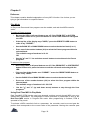
Chapter 5
Reference
This chapter contains detailed explanations of every MP-2 function. Use it when you are
trying to get information on a specific feature.
Play Mode
In Play mode Preset and User programs can be recalled, and real-time MIDI control is
active.
To select a Preset program:
•
Be sure the LEDs in all panel buttons are off. If the PRGM EDIT or SYSTEM
EDIT button LEDs are lit, press the button to exit the edit mode and extinguish
the LED.
•
If the top line of the display says "USER," press the PRESET/ USER button to
make it say "PRESET."
•
Use the BANK UP or BANK DOWN button to select the desired bank (0 or 1).
•
Press one of the number buttons (0-9) to select the Preset program within the
selected bank.
The available range of numbers is 01-39.
OR
•
Use the "∧" and "v" (up and down arrow) buttons to step through the Preset
programs.
To select a User program:
•
Be sure the LEDs in all panel buttons are off. If the PRGM EDIT or SYSTEM EDIT
button LEDs are lit, press the button to exit the edit mode and extinguish the
LED.
•
If the top line of the display says "PRESET," press the PRESET/USER button to
make it say "USER."
•
Use the BANK UP and BANK DOWN buttons to select the desired bank.
•
Press one of the number buttons (0-9) to select the User program within the
selected bank.
The available range of numbers is 01-128. OR
•
Use the "∧" and "v" (up and down arrow) buttons to step through the User
programs.
Using Real-Time MIDI in Play Mode
Real-Time MIDI (RTM) lets the user have dynamic, real-time control through MIDI over up to
sixteen MP-2 parameters. The assignment of MIDI controllers to parameters is done in the
Real-Time MIDI section in Program Edit mode. After programming is finished, RTM is
operated in Play mode.
To activate a MIDI controller's link to a parameter, the controller must be moved past the
position that corresponds to the current value of the parameter. Moving the controller past
Page: 33
this point "activates" the parameter. When there are multiple parameters assigned to a single
controller, the controller will usually need to be "swept", or moved through its entire range, to
activate all parameters. (This is also true when using RTM Preview in Program Edit mode.)
Program Edit Mode
In Program Edit mode, all sound parameters and MIDI parameters that are specific to each
program are defined.
To enter Program Edit mode:
• Press the PRGM EDIT button. The LED will light.
To select and adjust a parameter:
•
Press the button corresponding to the section containing the parameter to be
adjusted (for example, Tube voicing, Graphic EQ, Stereo Effects Loop, etc.).
•
Use the "<" and ">" (left and right arrow) buttons to move the cursor (indicated
by "->") to the parameter to be adjusted.
•
Some sections have more than one screen of parameters, indicated by an arrow in
the lower right corner.
After stepping through all parameters in a screen, pressing the ">" button will
step the display to the following screen, if there is one.
Similarly, previous screens are reached by pressing the "<" button to reach the
first parameter on a screen, then once more to step to the preceding screen.
• Once the desired parameter is selected, use the "∧" and "v" (up and downarrow)
buttons to adjust the value. Pressing the button once increments or
decrements the value by one; holding the button down causes the value to
scroll.
To exit Program Edit mode:
•
Press the PRGM EDIT button. If any parameters have been changed, this
initiates the Store sequence described below. When that sequence is complete,
the LED will go out and the MP-2 will be in Play mode.
Storing, Abandoning, and Resuming Edits
The MP-2 asks if you wish to store whenever you attempt to exit Program Edit mode after
having altered any of a program's parameters.
•
Press the PRGM EDIT button to exit Program Edit mode. The display will briefly
show:
Page: 34
then change to:
The User program value shown is the last User program used by the MP-2. Note that only User
programs are available for storing.
• Use the BANK UP, BANK DOWN, and number buttons in the same fashion as
recalling a program in Play mode to select a User program other than the one
shown.
•
When the desired User program is selected, press the "∧" button to answer
"Yes" to the query. The MP-2 will ask for confirmation:
•
Press the "∧" button again to answer "Yes" and complete the store.
To abort the store process and return to editing:
•
Press the PRGM EDIT button to reenter Program Edit mode. Select a section
and continue editing. All parameters will be as they were when you first
attempted to exit Program Edit mode.
To abort the store process and discard the changes to the program:
•
Press the "v" button when the "Store in User Program 128? Y/ N" message
appears to answer "No."
•
Press the "∧" button to answer "Yes" when the above message appears.
After the above message appears, the MP-2 will be in Play mode.
• Pressing the " v" button to answer "No" to the abandon message will return you to the
store message.
NOTE: It may helpful to refer to the signal flow diagram at the front of the manual to understand
the position of the following functions.
Page: 35
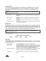
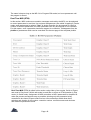
Tube Voicing
Selects basic character of tube sound by configuring the four tube stages and biasing them
for the proper gain and interstage EQ. There are ten Voicings available:
Table 1: Tube Voicings
1
2
3
4
5
6
7
8
9
10
Crystal Clean
Spanky Clean
Fat Clean
Vintage Brown
Warm Vintage
Dynamic Vintage
Warm Hi Gain
Dynamic Hi Gain
Ultimate Hi Gain
Fat Hi Gain
Drive & Master Level
Controls amount of signal fed to tube preamp.Use Master Level to balance relative levels of
different User programs.
Drive (0/100):
Master (0/100):
OD [Overdrive] (0/100):
Determines the amount of gain in the tube
preamp.
Sets output level from tube preamp into other
sections.
Available only when Hi Gain tube Voicings
(7-10. see above) are selected. Determines
how extreme distortion generated in the preamp is.
Compressor
The Compressor is the first stage a signal reaches from the input jack, preceding the tube
preamp.
Status (In/Out):
Ratio (1.5:1/30:1):
Threshold (0/100):
Gain (0/100):
Switches Compressor in and out of the signal path.
Sets compression ratio (increase in output for a given increase
in input). Available values are: 1.5:1, 2:1, 3:1, 4:1, 6:1, 8:1,
10:1, 15:1, and 30:1.
The higher the compression ratio, the more "squeeze" (gain
reduction) is applied to the signal.
Found on screen 2. The Compressor reduces gain (squeezes)
signals exceeding the Threshold value, and increases gain
(amplifies) signals below the Threshold. The COMP THRESH
LED will light whenever the signal exceeds the Threshold and
Compressor Status is set to "In".
Found on screen 2. Sets the amount of gain
applied to the compressor output to make up for level lost as a
by-product of compression. Lower Thresholds and higher
Ratios will generally necessitate higher Gain settings. It is
recommended that Gain be adjusted until the basic signal level
does not appear to change when the Compressor is switched
in and out.
Page: 36
Tone Controls
The Tone controls give fast access to tonal shaping. Use the Tone controls to get a basic
tonal sound and the Graphic EQ for more specific shaping needs. The actual frequencies
affected by the Tone controls sometimes change with different tube Voicings to give the
best sound.
NOTE: Simultaneously pressing the "∧ " and "v " buttons resets the Tone Controls to
flat response (all bands to 0 dB).
Lo (+12/-12):
Shapes the amount of low (bass) frequencies in the signal in 2
dB steps.
Mid (+12/-12):
Shapes the amount of midrange frequencies in the signal in 2
dB steps.
Shapes the amount of hi (treble) frequencies in the signal in 2
dB steps.
Shapes the amount of presence (upper mid) range frequencies
in the signal in 2 dB steps.
Hi (+12/-12):
Presence (+12/-12):
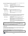
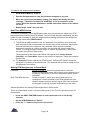
Graphic EQ
Graphic EQ provides fine tonal shaping by allowing adjustment of nine specific frequencies.
Up to 12 dB of boost or cut can be applied in two dB steps at any of the frequencies. The
display gives a graphic indication of the frequency currently selected and the complete EQ
curve. The upper right corner of the display always shows the frequency currently being
edited, with the amount of boost or cut at that frequency shown directly below it.
NOTE: Simultaneously pressing the "∧" and "v" buttons resets the Graphic EQ to flat
response (all bands to 0 dB).
The frequencies are:
100 Hz
1.3kHz
Table 2: EQ Frequency Centers
170 Hz
280 Hz
470 Hz
800 Hz
2.2kHz
3.8kHz
6.3kHz
Wah Filter
The Wah Filter follows the Compressor and precedes the tube stages. It can be swept by
using a MIDI controller, with a sweep triggered by playing dynamics, or with an onboard
sweep oscillator (LFO).
Status (In/Out):
Mode (Pedal):
Wah Pedal (0/100):
(Triggered):
Switches Wah Filter in and out of the signal path.
Enables Wah Filter to be swept by a MIDI controller. A MIDI
controller must be assigned in the Real-Time MIDI section to
control Wah Pedal in order for this function to work. For more
information see the description of Real-Time MIDI below.
Found on screen 2 when Pedal Mode is selected. Sets the
frequency in the filter at which the pedal's sweep begins.
Causes Wah Filter to be activated according to input signal
level.
Page: 37
Sensitivity (0/100):
Delay (0/100):
Start Point (0/100):
(Auto):
Depth (0%-100%):
Rate (0 Hz-10 Hz):
End Point (0-100):
Waveform (Sin/Tri):
Found on screen 2, available only when Triggered Mode is
selected. Sets the sensitivity of the trigger mechanism.
Found on screen 2. available only when Triggered Mode is
selected. Slows down the triggered sweep action.
Found on screen 3 when Triggered Mode is
selected. Sets the frequency in the filter at which the triggered
sweep begins.
Causes Wah Filter to be swept by the onboard
sweep oscillator.
Found on screen 2, available only when Auto
Mode is selected. Sets the range of the sweep (how much the
frequency moves).
Found on screen 2, available only when Auto Mode is selected.
Adjusts the rate of the sweep in 1/10 Hz steps.
Found on screen 3. available only when AutoMode is selected.
Sets the frequency in the filter at which the sweep ends.
Found on screen 3. available only when AutoMode is selected.
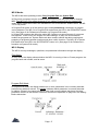
Selects either a sine or triangle shape for the sweep.(See
illustration of LFO waveshapes on next page.)
Tremolo
Tremolo is a pulsating volume effect controlled by an onboard sweep oscillator.
Status (In/Out):
Switches Tremolo in and out of the signal
path.
Waveform (Sin/Tri/Surf): Selects a sine, triangle, or "surf" shape for the LFO that
modulates the signal to create the tremolo effect.(See
illustration of LFO waveshapes.)
Depth (0%-100%):
Rate (0 Hz-10 Hz):
Found on screen 2. Sets the intensity of the
tremolo effect.
Found on screen 2. Adjusts the rate of the
tremolo effect in 1/10 Hz steps.
Noise Reduction
Some amount of noise is unavoidable in guitar preamplification, especially when applying
high gain, but it is usually only noticeable when nothing is being played. The Noise
Reduction section offers tools to eliminate noise when there is no signal. The Fader mode
fades sound slowly when the signal falls below the Threshold, while the Gate mode turns
Page: 38
the signal off instantly and completely. In general, Fader mode is recommended for lower
gain programs, and Gate mode for high gain programs.
Status (In/Out):
Mode (Fader/Gate):
Threshold (0-100):
Switches Noise Reduction in and out of the
signal path.
Selects the Noise Reduction operating mode.
Found on screen 2. Signals exceeding the Threshold are
heard unaltered, while signals below the Threshold are faded
or gated to silence.
Stereo Chorus
The Stereo Chorus is the point at which the input signal becomes stereo.
Status (In/Out):
Switches the Stereo Chorus in and out of the signal
path.
Depth (0%-100%):
Found on screen 2. Sets the intensity of the Chorus
effect.
Rate (0 Hz-10 Hz):
Found on screen 2. Adjusts the rate of the Chorus
effect in 1/10 Hz steps.
Stereo Effects Loop
Following the Chorus, each channel of the signal feeds its own effects loop, the left channel
being loop A and the right channel loop B. The loops are in a send/return configuration and
both the Sends and Returns are only active when Effects Loop Status is set to In.
Status (In/Out):
Mix A (0-100%):
Mix B (0-100%):
Switches the Effects Loop Sends and Returns in and out of
the signal path.
Found on screen 2. active only when Status is set to "In."
Adjusts the mix of "wet" signal from Effects Loop Return A
with "dry" (original) signal. The higher the percentage, the more
effects will be heard.
Found on screen 2. active only when Status is set to "In."
Adjusts the mix of "wet" signal from Effects Loop Return B
with "dry" (original) signal. The higher the percentage, the more
effects will be heard.
NOTE: Even when Effects Loop Status is set to "In ", the Effects Loop Sends can be
disabled through MIDI if FX Send Mute is selected in the Real-Time MIDI section as a
parameter to be controlled. If you are unable to get signal from the Effects Sends when
Status is set to "In", check Real-Time MIDI for this parameter.
Program Title
This is where the user can create his/her own name for a program before storing it. Upper
and lowercase letters, numbers 1 through 0, and various symbols are available for naming. A
name can have up to 16 characters or spaces.
The "<" and ">" buttons move the cursor from character to character, while the "∧" and "v"
buttons select the letter, number or symbol. The blank space character can be found
between the "?" and "A" characters
NOTE: Simultaneously pressing the "A" and "v" buttons clears the Program Title (all
characters blank).
Page: 39
The name is kept as long as the MP-2 is in Program Edit mode, but is not permanent until
the program is stored.
Real-Time MIDI (RTM)
In this section, MIDI continuous controller messages received by the MP-2 can be assigned
to control parameters in real time. Up to sixteen assignments (also called "mappings") can be
made; each assignment is called a "slot." A single controller can be mapped to control a
number of different parameters, but each parameter can only be mapped to one controller.
For this reason, once a parameter has been mapped to a controller, it disappears from the
picklist of parameters which can be controlled. On the next page is the complete picklist.
Real-Time MIDI (RTM) is edited in this section using either of two modes, Quick or Expert,
and used in Play mode. (Which edit mode is used has no effect on RTM operation in Play
mode.) In Quick mode, assignment of MIDI controllers to MP-2 parameters is simplified to
make the process as fast and easy as possible, allowing only the parameter being
controlled to be viewed. Expert mode involves a few extra steps which allow direct
selection and viewing of slot number, controller number, controller sense and minimum
and maximum parameter values.
Page: 40
The Real-Time MIDI Preview feature enables the effect of RTM assignments to be
auditioned without leaving the RTM section or Program Edit mode.
NOTE: Be sure a MIDI controller is properly connected to and set up to communicate
with the MP-2 before attempting to work with RTM.
RTM Edit Mode (Quick/Expert):Sets edit level for programming RTM.
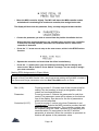
Macros
In Quick mode, eight additional entries appear in the parameter picklist for continuous
controllers. These are macros, factory-programmed groups of parameters that are all
changed simultaneously by the controller assigned to that slot. Macros do use up multiple
slots. Here is a list of macros and descriptions:
Table 4: Macro Descriptions
V-CURVE
Goes from mid-rangy EQ to extreme V-shaped curve with only a
slight level change.
GRIND
Goes from barely distorted (pedal back) to heavy grind (pedal
forward). Tweaked for use with high gain voices.
STEREO FX MIX
Controls both A and B Effects Loop Mixes at the same time.
SUSTAINER
Great for going from rhythm to lead, but continuously variable.
Brings in more gain, fat mids, and overall volume, while taking out
the noise gate for infinite sustain with no gate "chatter". Designed
for high-gain voices.
MELLOW WAH A
Pedal Wah that doesn't sound harsh or take your head off when
using Stratocasters or other bright guitars. The program must have
Wah Filter Status set to "In" and be in Pedal mode.
AUTO-WAH/TREM
Crossfades between two different automatic effects. Cocking the
pedal forward gets you AUTOWAH, and brining it back gradually
makes it TREMOLO. The program must have Tremolo Status set
to "On", Tremolo Waveform set to "Surf, Wah Filter Status set to
"On", and Wah Mode set to "Auto".
T-WAH DEPTH
The more forward the pedal is pushed, the more prominent the
Triggered Wah effect, but when the pedal is moved back it doesn't
become muffled because the Wah Start Point moves up.
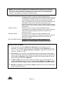
Table 4: Macro Descriptions
MODULATION
An organ modulation sound. Tremolo Status and Chorus Status
must both be set to "On" in the program.
Macros may be examined and altered in Expert mode, and the resulting, altered RTM
assignments may be stored, but user-altered-or -created assignments are not stored as
Macros, that is, they cannot be titled and do not appear in the picklist.
Page: 41
To examine the components of a Macro:
•
Set RTM Edit Mode to "Expert".
•
Use the Slot parameter to view the parameter assigned to any slot.
•
Move the cursor to the Parameter setting. The display will briefly show the
message, "THIS SLOT IS PART OF A MACRO" if it is a component of the
macro. After the message disappears, the MP-2 will allow editing of the setting
as usual.
•
Repeat steps 2 and 3 for each slot.
Real-Time MIDI Preview
This feature, available in Quick and Expert modes, lets you evaluate the effect of an RTM
assignment without leaving the RTM section. This is not only simplifies auditioning, but also
means it is not necessary to store the program before hearing the effect of the assignment.
Here are a few notes about RTM Preview:
1) To activate the MIDI controller's link to a parameter, the controller must be moved
past the position that corresponds to the current value of the parameter. Moving the
controller past this point "captures" the parameter. When there are multiple
parameters assigned to a single controller, the controller will usually need to be
"swept", or moved through its entire range, to capture all parameters. (This is also
true when using RTM in Play mode.)
The exceptions to this are the two Global audio parameters, Stereo Volume
Controller, and Tuner Mute, which do not need to be captured. These are located in
System Edit.
2) The Compare function operates in RTM Preview. "INITIAL SETTINGS" resets the
parameter in question to the stored value. The controller will need to be swept to hear
the difference in the effect.
Making RTM Assignments in Quick Mode
Parameter:
Real Time MIDI Preview:
Found on screen 2. Selects the parameter for real-time
control.The parameter name will be shown on the bottom line of
the display. See above for the list of parameters which can be
controlled.
Found on screen 3: active only when Parameter is not
Unassigned". Allows operation of an RTM assignment to be
checked without having to leave Program Edit mode and store
the program by moving controller and listening to the result.
General procedure for making RTM Assignments in Quick mode:
This is an abbreviated version of the procedure given in the Tutorial, reproduced here for
convenience.
•
Press the REAL-TIME MIDI button to enter the section if it is not already
selected.
•
•
Set the RTM Edit Mode to "Quick".
Press the ">" button to step to the next screen.
Page: 42
•
Move the MIDI controller slightly. The MP-2 will detect the MIDI controller number
and whether it is a switch-type or continuous controller, then assign it to the slot.
The display will then show the parameter, if any, currently assigned to that controller.
•
Choose the parameter you wish to control from the picklist of available choices.
Notice that only toggle parameters are available when a switch-type controller
is detected, and only variable parameters are available when a continuous
controller is detected.
•
Press the ">" arrow once to step to the next screen, which is the RTM Preview
function.
•
Operate the controller and check that the effect is satisfactory.
•
Press the "<" button when you are finished previewing and the display will
return to the "Move Pedal or Press Switch" message. You are ready to assign
your next controller.
Making RTM Assignments in Expert Mode
NOTE: Real-Time MIDI control of parameters does not function in Program Edit mode,
except in Real-Time MIDI Preview. Also, remote parameter editing through MIDI is limited to
the Sense and Range parameters when the Real-Time MIDI section is active.
Slot (1-16):
Parameter:
Controlled (0-127):
Found on screen 2. Chooses one of the six teen slots for
editing.The slot number is simply a designation which
makes no functional difference.
Found on screen 2. Selects the parameter for real-time
control.The parameter name will be shown on the bottom
line of the display. See above for the list of parameters
which can be controlled.
Found on screen 3: active only when Parameter is not
"Unassigned". Selects the MIDI controller number that will
affect the selected parameter. The controller number can
be selected using the A and v buttons or by operating the
controller while it is connected to the MP-2 and this
parameter is selected. When the controller is operated, its
number will appear in the parameter value.
Page: 43
NOTE: If the controller is operated and its number does not appear in the Controller
#parameter value check MIDI connections and verify that the controller and the MP-2
are set to the same channel. The MIDI Monitor function found on of the Reference
chapter is very helpful for this type of troubleshooting.
Sense(Forward/Reverse):Found on screen 3: active only when Parameter is not
"Unassigned" and controller is continuous (not switch). When set
to Forward, the selected parameter increases in value when the
incoming MIDI controller values increase (pedal is pushed
down), and decrease as the controller values decrease (pedal is
pulled back). When set to Reverse, the parameter value
decreases when the controller value increases (pedal is pushed
down), and increases as the controller values decrease (pedal is
pulled back).
Minimum Value:
Found on screen 4: active only when Parameter is not
"Unassigned" and controller is continuous (not switch). Sets the
value of the selected parameter when the controller is at
its minimum value.
Maximum Value:
Found on screen 4: active only when Parameter is not
"Unassigned" and controller is continuous (not switch). Sets the
value of the selected parameter when the controller is at
its maximum value.
Real Time MIDI Preview: Found on screen 5; active only when Parameter is not
"Unassigned". Allows operation of RTM assignment to be
checked by moving controller and listening to the result.
NOTES on Real-Time MIDI:
1) The range and units of the Minimum or Maximum value will depend on the
parameter. For example, when Drive is the selected parameter, Minimum can vary
from 0 to 100, but when Graphic EQ Band 1 (100 Hz) is selected, the minimum can
vary from -12 dB to +12 dB
2) When Sense is set to "Reverse ", the relationship between controller value and parameter
value is inverted, that is, the lowest controller value (pedal pulled all the way back) will set
the parameter to Maximum, and the highest controller value (pedal pushed all the way
down) will set the parameter to Minimum.
3) The Min and Max values can never exceed the existing value of the parameter. If, for
example, the Drive parameter is set to 30, any attempt to set Min higher or Max lower than
30 will result in the error message, "MIN. (or MAX) IS NOW EQUAL TO PARAM. VALUE."
4) Min, Max, and Sense are not available for Status parameters, as these are switches with
only two values (In and Out).
Page: 44
General procedure for making RTM assignments in Expert Mode:
•
Press the REAL-TIME MIDI button to enter the section if it is not already
selected.
• Set RTM Edit Mode to "Expert".
•
Select Slot to be programmed.
•
Select Parameter to be controlled.
•
Select MIDI Controller number.
•
Set the controller Sense.
• Set the Minimum and Maximum allowable values for the parameter under
control.
•
Check the operation of the mapping in Real-Time MIDI Preview.
NOTE: Simultaneously pressing the "∧" and "v" buttons clears all Slots (unassigns all
parameters).
Compare
This feature allows comparison, without leaving Program Edit mode, between an edited
(Modified) version of a program and the stored version (Original). Each time the Compare
button is pressed, the MP-2 switches between the versions, allowing each to be heard. The
display indicates whether it is switching to the edited version ("MODIFIED SETTINGS") or
the stored version ("INITIAL SETTINGS").
System Edit Mode
Utility functions and MIDI parameters which are global (in effect for all programs) are found
in System Edit mode. Many functions in this mode have procedures of several steps which
are entered with the up arrow.
Page: 45
MIDI Function Menu
The MP-2's basic MIDI functions, as well as some of its most advanced ones, are accessed
through the MIDI function menu. Unlike the other selections in the System Edit mode, the
MIDI Function menu is not a single function, but a submenu of a number of functions.
The MP-2 can send and receive the following kinds of MIDI messages: Program Change
(which can also be remapped), Continuous Controller (used for both Global and RTM
functions), and System Exclusive (which can contain the settings for a single program or all
User programs).
To access the MIDI Function menu:
•
Press the "∧" button when the display shows the message "MIDI FUNCTION
MENU?"
To move through the MIDI Function menu:
•
Press the ">" button from any main menu entry to step to the next entry.
Many entries have additional screens. It is usually necessary to use the "<"
button to "back out" of these screens and return to the main menu.
To exit the MIDI Function menu:
•
Press the "<" until the display again shows the message "MIDI FUNCTION
MENU?"
About Global MIDI Parameters
Global parameters are settings that apply no matter what program is running. The MIDI
channel and program map, for example, do not change when the program is changed, nor
do the Pedal Edit Controller, Stereo Volume Controller, or Tuner Mute.
This is most important to know for the last two. The fact that the Stereo Volume Controller is
Global, means that it can be set to achieve a good basic level that blends with the band,
which is maintained when a new program is recalled. Likewise, if you step on a program
change footswitch while the Tuner Mute is engaged, the outputs will stay muted when the
new program is recalled.
Page: 46
Set MIDI Channel
This parameter sets the MIDI channel over which the MP-2 will transmit and receive. It can
be set to any of the 16 MIDI channels, ALL for Omni mode (responds to MIDI information
arriving on any channel), or OFF to disable MIDI reception.
NOTE: When the MP-2 's MIDI Channel is set to "All" or "Off", program changes are
transmitted on channel 1.
Edit MIDI Mapping
The MP-2 can map (assign) each incoming MIDI program change number to recall any User
program. A single User program may be mapped to many
MIDI program change numbers.
NOTE: Preset programs cannot be recalled through MIDI, only from the front
panel.
To create a MIDI Program Change map:
•
Press the "∧" button when the display shows the message "EDIT MIDI
MAPPING?" to access the map.
•
Use the "∧" and "v" buttons to select the MIDI program change number you
wish to map.
•
Press the ">" button to move the cursor to the User program value.
•
Use the "∧" and "v" buttons to select the User program you want recalled when
the selected MIDI program change number is received.
•
Press the "<" button to move the cursor back up to the MIDI program change
value and repeat steps 2-5 as many times as necessary until program changes
have been mapped as desired.
It is not necessary to map every program change; the default mapping will call
the User program with the same number as the MIDI program change.
•
When mapping is complete, press the " < " button to return to the MIDI Function
menu.
To restore the default map (1 to 1 mapping. User program # = MIDI program #):
•
Press the ">" button while in the mapping screen until the display shows the
message "RESET MIDI MAPPING?"
•
Press the "∧" button to continue. The display will ask for confirmation.
•
Press the "∧" button to restore the default map.
To abandon restoring the default map:
•
When the display asks for confirmation, press the down arrow. The display will
return to the Reset screen.
•
Press the left arrow to exit the Reset function and return to the mapping screen.
Page: 47
MIDI Mismatch Warning (On/Off)
The most common cause of MIDI problems is having the MIDI controller and the MIDI
"slave" device (in this case, the MP-2) not set to the same channel. When MIDI Mismatch
Warning is set to "On," the MP-2 will warn you if it receives MIDI messages on a channel
other than the one to which it is set.
On:
Off:
The MP-2 will display the messages, "MIDI
CHANNEL MISMATCH," "CHECK MIDI SETTINGS" if it
receives MIDI messages on a different channel than its own.
No warning messages are given.
Enable MIDI Monitor
When troubleshooting MIDI problems it is often helpful to be able to see what MIDI
messages the MP-2 is receiving. This ability can also be useful simply to see what kinds of
messages another MIDI device is transmitting. The MIDI monitor displays, in real time, all
MIDI controller and program change messages being received by the MP-2.
To enable MIDI monitoring:
•
Press the "∧" button when the display shows the "ENABLE MIDI MONITOR?"
message.
To exit MIDI monitoring:
•
Press the "<" button to return to the MIDI Function menu.
Send Library
The MP-2 can transmit or receive all User programs over MIDI (as System Exclusive
messages) to a librarian or sequencer program or another MP-2.
To send all User programs over MIDI:
•
Connect MIDI Out of the MP-2 to MIDI In of another MP-2 or a MIDI interface
hooked up to a computer running a librarian or sequencer program.
•
Press the "∧" button when the display shows the "SEND LIBRARY?" message.
The display will verify that the operation has been completed.
NOTE: In order to receive a program or other System Exclusive messages, the MP-2
must be in Play mode with Memory Protect "OFF."
Send Current Program
The MP-2 can transmit the contents of the program currently being edited over MIDI (as
System Exclusive messages) to a librarian or sequencer program, or receive a program from
another MP-2.
To send the current program over MIDI:
•
Connect MIDI Out of the MP-2 to MIDI In of another MP-2 or a MIDI interface
hooked up to a computer running a librarian or sequencer program.
•
Press the "∧" button when the display shows the "SEND CURRENT
PROGRAM?" message. The display will verify that the operation has been
completed.
Page: 48
NOTE: In order to receive a program or other System Exclusive messages, the MP-2
must be in Play mode Memory Protect "OFF."
Pedal Edit Controller
One of the MP-2's most powerful MIDI features is the ability to edit parameters remotely from
a MIDI controller. The designated controller will vary the value of the currently selected
parameter in Program Edit mode, making possible hands-free parameter editing. This should
not be confused with real-time MIDI operation, which does not alter the value in the MP-2's
working memory and is only active in Play mode.
The controller number can be selected using the ∧ and v buttons or by operating the
controller while it is connected to the MP-2 and this parameter is selected. When the
controller is operated, its number will appear in the parameter value.
NOTES:
1) If the controller is operated and its number does not appear in the Controller #
parameter value check MIDI connections and verify that the controller and the MP-2 are
set to the same channel. The MIDI Monitor function is very helpful for this type of
troubleshooting.
2) The Pedal Edit Controller function is limited to the pedal SENSE and RANGE
parameters in the Real-Time MIDI section.
Stereo Volume Controller
In addition to any volume parameters under control of RTM, the MP-2 offers Global control
of stereo volume through MIDI. This volume control follows everything else in the signal path
except the front panel Output Level pot.
The controller number can be selected using the "∧" and "v" buttons or by operating the
controller while it is connected to the MP-2 and this parameter is selected. When the
controller is operated, the number will appear in the parameter value. When set to "Out", no
MIDI volume control is enabled (unless in Real-Time MIDI).
NOTE: If the controller is operated and its number does not appear in the Controller #
parameter value check MIDI connections and verify that the controller and the MP-2 are
set to the same channel. The MIDI Monitor function is very helpful for this type of
troubleshooting.
Tuner Mute Control
If is often necessary to tune while in play, however, it is not desirable for the audience to
always hear that process. The Tuner Mute, when activated by a selected MIDI controller,
shuts off audio to all of the MP-2's outputs, allowing a tuner connected between the
instrument and the MP-2 to be used silently. It is a Global parameter which remains in effect
regardless of the program running.
The controller number can be selected using the "∧" and "v"buttons or by operating the
controller while it is connected to the MP-2 and this parameter is selected. When the
controller is operated, the number will appear in the parameter value. When set to "Out", no
Page: 49
mute control is enabled.lt is recommended that one of the MIDI switch controllers be used for
this purpose, such as CC 64 (Sustain Pedal).
NOTE: If the controller is operated and its number does not appear in the Controller
#parameter value check MIDI connections and verify that the controller and the MP-2
are set to the same channel. The MIDI Monitor function is very helpful for this type of
troubleshooting.
Copy Presets to User
The factory Preset programs can be reloaded into User programs at any time.
To reload Preset programs:
•
Press the "∧" button when the display shows the message "LOAD PRESET
PROGRAMS?" The display will ask for confirmation.
•
Press the "∧" button to reload the Preset programs or the down arrow to
abandon the reload.
WARNING! Loading the Preset programs will erase the contents of User memories
1-39.
Copy Single Programs
Programs may be copied from any location, Preset or User, into any User program.
To copy a program:
•
Press the "∧" button to access the second screen.
•
Use the BANK UP, BANK DOWN, and number (0-9) buttons to select the source
location. The Bank buttons will step first through all User banks, then through
the Preset banks.
•
Use the right arrow to move the cursor to the destination (TO:) parameter.
•
Use the BANK UP, BANK DOWN, and number (0-9) buttons to select the
destination User location. Programs can only be stored in User memories.
•
Press the up arrow when the source and destination memories have been
selected. The display will ask for confirmation.
•
Press the up arrow to complete the copy. The display will show the message,
"DONE!" to verify that the procedure is complete.
To abandon a copy procedure:
•
When the confirmation message appears, press the down arrow to abandon the
copy. The display will return to the selection screen.
•
Press the left arrow to exit the copy function or select new source and
destination values and continue with the copy.
Page: 50
Swap Programs
Programs may be swapped between any two User memories.
To swap a program:
•
Press the up arrow to access the second screen.
•
Use the BANK UP, BANK DOWN, and number (0-9) buttons to select the source
(SWAP:) location.
•
Use the right arrow to move the cursor to the destination (WITH:) parameter.
•
Use the BANK UP, BANK DOWN, and number (0-9) buttons to select the
destination location.
•
Press the up arrow when the source and destination memories have been
selected. The display will ask for confirmation.
•
Press the up arrow to complete the swap. The display will show the message,
"DONE!" to verify that the procedure is complete.
To abandon a swap procedure:
•
When the confirmation message appears, press the down arrow to abandon the
copy. The display will return to the selection screen.
•
Press the left arrow to exit the swap function or select new source and
destination values and continue with the swap.
Panel Mode
Panel Mode offers the ability to make the MP-2's front panel act like a MIDI controller when
recalling programs. This is useful if you are accustomed to using a MIDI controller and are
more familiar with the MIDI program change numbers associated with a program than with
the MP-2 User program number or if your MIDI program change footswitch fails onstage. (In
that situation, you would simply move the cable plugged into MIDI Thru to MIDI Out and use
the front panel to send program changes to the rest of your MIDI gear.)
Local:
Normal operation.
Controller:
Front panel program selection in Play mode
uses the MIDI Program Change Map; in other words, the front
panel buttons act like a MIDI controller when recalling
programs, including transmitting the number entered from the
front panel as a MIDI Program Change message.
When this mode is selected, the display in Play mode will show
the MIDI program change number and the User program to
which it is mapped, but the map is not editable from this
screen. Editing of the map can only be done in the MIDI
Function menu.
Page: 51
Restore System Defaults
The default values for the System parameters listed here can be restored at any time:
Restoring the System defaults also resets (unmutes) the Tuner Mute, and resets the Stereo
Volume to full on (100%).
To restore factory System default values:
•
Press the up arrow when the display shows the "RESTORE SYSTEM DEFAULTS?"
message. The display will verify that the operation has been completed.
Memory Protect
The memory protect function, when engaged, disables the ability to accept SYSEX
messages, and to store edited programs.
Off:
Normal operation; edited programs may be stored into User
memories.
On:
Store function and SYSEX load capability disabled.
Page: 52
Appendix A
Specifications
Inputs (Front and Rear)
Connectors:
Maximum Input Level:
Input Impedance:
Unbalanced (TS) 1/4" phone. Front panel jack overrides rear
panel jack.
+12.2 dBV (3.4V RMS)
390 kilohms
Stage Outputs
Connectors:
Unbalanced (TS) 1/4" phone
Maximum Output Level: +11.1 dBV (3.6V RMS) into 600 ohms
+ 17.1 dBV (7.2V RMS) into 50 kilohms
Output Impedance:
500 ohms
Recording Outputs
Frequency Response:
Bandwidth limited to approximately 50 Hz-3 kHz
Connectors:
Balanced 3-pin XLR (pin 3 hot) Unbalanced (TS) 1/4" phone
Maximum Output Level:
Unbalanced:
+11.1 dBV (3.6V RMS) into 600 ohms
+17.1 dBV (7.2V RMS) into 50 kilohms
Balanced (Line):
+12 dBV (4V RMS) into 600 ohms
Balanced (Mic):
-16 dBV (.15V RMS) into 200 ohms
Output Impedance:
500 ohms
Effects Loops Sends
Connectors:
Unbalanced (TS) 1/4" phone
Maximum Output Level:
Line:
+11.1 dBV (3.6V RMS) into 600 ohms
+17.1 dBV (7.2V RMS) into 50 kilohms
Instrument:
-8.9 dBV (.36V RMS) into 600 ohms
-2.9 dBV (.72V RMS) into 50 kilohms
Effects Loop Returns
Connectors:
Maximum Input Level:
Line:
Instrument:
Input Impedance:
+20 dBV (10V RMS)
0 dBV (1V RMS)
10 kilohms
Power Consumption:
35 watts
Size:
1.75" Hx 19"Wx9.5"D
Weight:
7 Ibs.
Unbalanced (TS) 1/4" phone
Page: 53
MP-2 MIDI Implementation Chart
Page: 54
Appendix B
MIDI and the MP-2
A brief discussion of the MIDI specification and the portions of it used by the MP-2.
MIDI (Musical Instrument Digital Interface) is the means by which computer-based electronic
musical instruments, such as synthesizers and samplers, and other related equipment can
exchange information. MIDI is a specification agreed upon by the manufacturers of this
equipment, and consists mostly of the definition of a number of software messages that,
taken collectively, comprise something that is part communications protocol, part computer
language, part file format. Technically, it is a one-way serial interface operating at a speed of
31.25 kilobaud. (Two-way MIDI communication is possible, it just entails using two cables
between the devices.) MIDI messages convey information about a musical performance,
though they do not actually carry sound. Think of the modern equivalent of a player piano:
the holes are MIDI note messages (which specify which note was played and how hard),
while the player piano actually producing the sound is a synthesizer or sampler.A sequencer
is a recorder of MIDI data, like a tape recorder, except that it doesn't use tape and it records
MIDI data, not sound. In other words, the sequencer is what takes an actual performance
and makes a MIDI "piano roll." In order to allow multiple devices to be simultaneously but
independently addressed, MIDI uses a channel system similar in concept to television.
When a device is set to one of the 16 MIDI channels, it will respond only to messages
carrying that channel number. Note messages are the most commonly used, but the MP-2
has no need of these. The next most common messages are program change messages.
These tell the receiving device to recall a specific program, or collection of settings, from its
memory. When the MP-2 receives a program change message, it recalls one of the User
programs; it is also capable of transmitting a program change message when a program is
selected from the front panel. MIDI is capable of specifying up to 128 different program
change numbers. The MP-2's MIDI Mapping feature lets you assign each MIDI program
change number to call up anv User program you desire. The MP-2's Panel Mode is a special
feature that allows the MP-2's front panel to act as if it were a MIDI controller plugged into
MIDI In. In this case, you press the MIDI program number on the front panel, and the MP-2
recalls the current User program currently mapped to that MIDI number.lt will also show that
mapping. Many MIDI systems consist of a number of components. In order to achieve the
maximum flexibility with the least effort, it was necessary to devise a system wherein a single
program change message from a source could call up desired programs in all the
components simultaneously, without having to constantly shuffle programs around in
memory to match a program change number.This is the purpose of the MP-2's program
change mapping capability.
Another common type of MIDI message is Continuous Control messages. These are
generally used to gestural controllers like Modulation Wheel and Volume.Interestingly,
switch-type controllers, like Sustain Pedal, are also in this category, even though they are
not actually continuous. The MIDI specification originally defined 124 different controllers,
but later enhancements to the spec allow many more to be defined. A few very important
controllers, notably pitchbend and aftertouch. have their own messages defined and are
not considered part of the Continuous Controller class. The MP-2 can use Continuous
Controller messages to control virtually any of the parameters available in Program Edit
mode, but it does not recognize pitch-bend or aftertouch. The last type of MIDI message
used by the MP-2 is System Exclusive. This type of message was originally intended as a
"trap door" to allow both expansion of the MIDI spec and use by manufacturers of features
unique to their devices. The definition of the basic System Exclusive is quite sparse and
open-ended to give manufacturers the greatest latitude. Each manufacturer uses their own
format for these messages, and only their devices or computer software specifically
Page: 55
designed to work with those devices will recognize them.There have been several more
structured additions to the MIDI spec that are defined as types of System Exclusive
messages, but it is the original use that the MP-2 employs. It is the MP-2's System Exclusive
implementation that lets libraries or programs be sent and received by the MP-2.Computer
software programs called librarians store and retrieve this kind of information. There are
numerous other types of MIDI messages that are not covered in this extremely brief
discussion because they are not appropriate to the job the MP-2 performs. For more
information on MIDI, there are several magazines that focus heavily on MIDI and its
applications, and a number of fine books on the subject.
Page: 56
Appendix C
Troubleshooting
Some hints to aid in correcting problems.
Problems happen, always at a critical moment when they can least be afforded. Fortunately,
the overwhelming majority of problems are simple in nature and usually involve no more
than finding and correcting some oversight.
Troubleshooting Tips
The difference between quickly fixing a problem and becoming angry and frustrated lies
mostly in the approach taken in troubleshooting. Here are a few rules that can be applied to
any troubleshooting situation:
1) Stay calm!
It is easy to become upset when a problem crops up, especially in a high-pressure situation
such as in the "heat of the battle" onstage, but panic tends to close the mind, making it more
likely that the fault will be overlooked. It may take a lot of effort to remain calm, but this is the
single most important troubleshooting technique.
2) Be methodical. Use the process of elimination to isolate the cause.
Time is frequently wasted in troubleshooting situations by attacking the problem randomly.
The most potent technique for finding the cause of a problem is the process of elimination.
The first thing to try is eliminating everything in the middle of a signal chain and see if the
problem still exists. Use any indicators or meters in the signal chain to help isolate where the
signal exists and where it does not. If you are getting no sound from the MP-2, for example,
try setting all Status parameters to "Out" and disabling the Stereo Volume Control. If there is
still no sound, the problem is either elsewhere or a truly serious one that cannot be dealt with
on the spot (which does happen on occasion). If the problem disappears, you have isolated
the cause as being something to do with the sections you removed. The next step is to add
them back in one at a time, testing as you add each stage. In this way, you will quickly
identify the culprit, allowing you to then focus on that area in the same way and find the
specific cause. This may sound like a procedure too time-consuming for a performance situation, but, in fact, it can be done very quickly once the process is familiar, and it offers the
best chance of actually finding and correcting the problem.
3) Don't overlook the obvious. Check simple mechanical things first.
When a problem occurs, don't immediately assume it is a complex MIDI mishap or some
other arcane thing; most often it is the simplest possible explanation that is the right one. Did
the unit become unplugged? Is it switched on? Are the connections correct and complete? (It
is easy for a cable to be half-plugged in, which can cause very puzzling behavior.) Is there a
bad cable?
Even once basic mechanical causes have been explored, continue thinking of the simplest
explanation. If the MP-2 is not responding to MIDI, check the channel settings after checking
the cabling connections.
Page: 57
Audio Problems
Aside from the general suggestions given above, here are a few specific things to check for:
Symptom
Unit does not power up
No sound, no signal LEDs
No sound, LEDs OK
Unwanted distortion
Hum
Possible Cause
Not plugged in
Not switched on
Fuse is blown in unit
Wall power is bad
Problem with instrument
Bad cable or connection going to MP-2
Some level parameter is set to zero.
Check: Master, Drive, OD, Loop A & B Mix
Stereo Volume Controller is set to zero
Gate Threshold is too high
Problem with amplifier/monitor system
Bad cable or connection going from MP-2
Output Level control set to zero
Tuner Mute is engaged
Some level parameter is set to zero, (see list above)
Bad cable going to or from the MP-2
Problem in instrument or amplifier/monitor system
Effects Loop or XLR Level switches set incorrectly
Too much level within MP-2 (indicated by signal LEDs
glowing red).
Bad cable
Problem in instrument or amplifier/monitor system
Ground loop (try Pin 1 Lift switch)
MIDI Problems
No response to controller
No response to
continuous controllers
Incorrect program changes
Does not receive library
or program
Incorrect or faulty MIDI cabling
MIDI channel not set to match controller
MIDI channel set to "Off
Incorrect RTM assignment Parameters under
control not "captured"
MIDI map improperly set up
Incorrect or faulty MIDI cabling
MIDI channel not set to match source
MIDI channel set to "Off
The MIDI Monitor function found in System Edit mode displays incoming controller and
program change messages. This can be very helpful in trying to isolate MIDI problems. The
MIDI Mismatch Warning function, also found in System Edit mode, when enabled, displays
a warning when the MP-2 receives MIDI messages on a different channel than that to which
it is currently set. This, too, can be useful in troubleshooting.
Page: 58