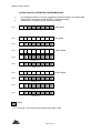
1
MIDI PROGRAMMABLE TUBE PRE-AMP OWNER’S MANUAL MP-1 (version 1) Originally written by ADA SIGNAL PROCESSORS, INC. Scanned and edited by Jur at 3 april 2002. Original ADA logo edited and rendered by Barend Onneweer of Raamw3rk.) The version of this manual is copyrighted and may not be sold or placed on a website without permission of the editor. Release No.1 for http://www.ada-mp1.com ADA MP-1 Owner’s manual CONTENTS 1.0 INTRODUCTION 1.1 QUICK SET-UP GUIDE 1.2 FEATURES 1.3 PRECAUTIONS 2.0 CONTROL FUNCTIONS 2.1 REAR PANEL 2.2 BATTERY 3.0 INITIAL SET-UP 3.1 ACCESSING PROGRAMS -CHANGE MEMORY NUMBER WITHIN THE SAME BANK -CHANGE TO NEW BANK AND MEMORY NUMBER 3.2 EDITING AND STORING PROGRAMS -EXAMINE PROGRAM PARAMETERS -EDIT AND STORE A PROGRAM 3.3 CREATING TONE 3.4 USING THE CLIP LEDS 3.5 USING THE EFFECTS LOOP 3.6 LOAD PRESET PROGRAMS 4.0 MIDI FUNCTIONS -SELECT MIDI CHANNEL -SELECT PROGRAM & MEMORY NUMBER 4. 1 ONE-TO-ONE MAPPING 4.2 REMOTE 5.0 SELF DIAGNOSTICS 6.0 MEMORY PRESET SETTINGS 7.0 SPECIFICATIONS 7.1 MIDI SPECIFICATIONS 7.2 SOFTWARE UPDATES 8.0 RETURNING UNITS FOR SERVICE 9.0 WARRANTY 9.1 OPTIONAL EXTENDED WARRANTY 9.2 TUBE REPLACEMENT 10.0 SYSTEM EXCLUSIVE MESSAGES 10.1 SYSTEM EXCLUSIVE MAP 10.2 SYSTEM EXCLUSIVE PARAMETER VALUES Page 2 of 26 ADA MP-1 Owner’s manual 1.0 INTRODUCTION Thank you for purchasing the ADA MP-1 MIDI Programmable Tube Preamp. You now own the most tonally flexible and technologically advanced guitar amplification device available. Your MP-1 will store 128 programs of exactly the right tone. (no matter what kind of music you play.) The MP-1 features a unique Tri-State Voicing selection that allows you to choose between Distortion Tube, Clean Tube, or Solid State circuits for each program. The EQ points were designed to replicate the sound of Fender and Marshall, but the Presence control surpasses the range offered by either. The stereo Chorus utilizes analog circuitry which complements the warmth of tubes to give you the best possible sound. The software in the MP-1 provides the fullest implementation of MIDI available. Since the MP-1 is software-based, it will never grow obsolete. As the MIDI standard evolves, your MP1 can be updated by simply changing the program ROM. In the manual, you will find references to different levels of software. When you power up your MP-1, the display indicates which level of software is installed. On power-up, "ADA" is displayed first, followed by a 3 digit number. The first of these digits is the level of software installed. To properly set-up and familiarize yourself with the MP-1, read and follow these operating instructions completely. If you can't wait and want to jump right into the MP-1, go to section 1.1 QUICK SET-UP. We hope that the unlimited tonal possibilities and unmatched technological capabilities of your MP-1 will inspire you to great things. IMPORTANT: Please take this time to fill-out and return the enclosed warranty card so we may provide you information on future software updates. Page 3 of 26 ADA MP-1 Owner’s manual 1.1 QUICK SET-UP GUIDE Note: The MP-1 is a preamp and must be connected to a power amp in order to play through loud speakers. INITIAL PREPARATION: 1. Connect guitar to front panel input jack. 2. Connect studio (line) level signals to the rear panel input jack. 3. Connect amplifier to one of the two rear panel outputs. For stereo, run both outputs to separate power amps. 4. If MP-1 outputs are connected to power amps (instead of guitar amps) or a professional mixing console, flip the top panel slide switch towards the rear panel to the Line position. 5. Turn power switch ON. 6. Adjust volume with Output Level control. SELECT MEMORY NUMBER: 1. Use ^ V buttons to scroll thru the memory numbers 1 thru 128. 2. Or select a bank by pressing the BANK button, select bank number 0 thru 12 using ^ V buttons, followed by pressing any button labeled 0 thru 9. CREATE THE RIGHT TONE: 1. Press EDIT button. 2. Select VOICING button. 3. Use ^ V buttons to select Clean Tube, Distortion Tube, 4. or Solid State circuit. 5. Select Master Gain. 6. Use ^ V buttons to change level of drive from 1 to 10. 7. Repeat steps 4 and 5 for Overdrive 1 and 2. In 8. Solid State mode, the level of Overdrive 2 controls the amount of compression. 9. Follow the same procedure for shaping Ea. 10. Select Chorus Depth button. 11. Use ^ V buttons to adjust depth from 0 to 100%. 12. Select Chorus Rate button. 13. Use ^ V buttons to adjust rate of sweep from .1 Hz to 10 Hz, or to turn rate off (0). 14. 12. To abandon this edit session, press EDIT button. LED's turned off and changes not saved. To store changes, see below. STORE YOUR TONE: 1. To store the new values that you have set press STORE button. 2. Select the(location (memory numbers 1-128) for storing your program. Page 4 of 26 ADA MP-1 Owner’s manual SELECT MIDI CHANNEL: 1. Press MIDI CHNL button. 2. Use ^ V buttons to select MIDI channel from 1 thru 16, ALL (OMNI) or OFF (MIDI reception off). 3. Press MIDI CHNL to save and exit. DIRECTING MIDI PROGRAM CHANGE INFORMATION TO DIFFERENT INTERNAL MEMORY NUMBERS: 1. Press PRGM button. 2. Select a MIDI program number by using the ^ V buttons to scroll thru MIDI program numbers1 thru 128 or select directly using BANK and 0 thru 12. 3. Press MEM button. 4. Select an internal memory number by using the ^ V buttons to scroll thru the 1-128 memory numbers or select directly using BANK and 0 thru 9. 5. Press MEM to save the change and to exit. LOAD PRESET PROGRAMS (1 thru 29) 1. Press STORE button. Press BANK, and while holding, press 1. Display shows "LP". 1.2 FEATURES Unique Tri-State Voicing option for choice of Clean Tube, Distortion Tube, or Solid State circuit for each program. Two low noise 12AX7 A/7025 tubes. 128 programs. Three programmable gain controls for each program. Four band programmable EQ including 16dB boost/cut for bass and treble. Fully programmable stereo chorus and doubler. Programmable effects loop with adjustable send/receive level. Stereo headphone jack with level control. Stereo outputs switchable from line level (to mixing board) to instrument level (to guitar amp). 1/4" instrument level input jack on front panel for easy access. Active balanced input on rear panel for mixing boards. Output level knob for fast volume adjustment without affecting tone. Programmable compression level in Solid State mode. Received MIDI program numbers are re-assignable (mapable) to any MP-1 memory number. MIDI In, Out and Thru. Selectable MIDI channel including ALL channels (OMNI) and no channels (OFF). Lexan membrane switch front panel replaces pots. No contamination from dust or liquids. Optional MC-1 MIDI CONTROLLER footswitch provides instant access to any program for on-stage control. Self-diagnostics check unit during power up. Instantaneous logic-controlled FET switching. EPROM updates will be available for future system expansion. State-of-the-art software implementation including SYSEX and MIDI Time Code for computer controlled applications. Simple programming routine. One year parts and labor warranty. Extended 3 year warranty available. Page 5 of 26 ADA MP-1 Owner’s manual 1.3 PRECAUTIONS WARNING: To prevent fire or shock hazard. do not expose this appliance to rain or moisture. Locate the MP-1 out of the direct rays of the sun. Avoid locations subject to vibration and excessive dust, heat, or cold. CAUTION: To prevent electric shock, do not remove cover. No user serviceable parts inside. Refer servicing, including tube replacement, to qualified service personnel. RETAIN INSTRUCTIONS: Keep this manual in a safe location for future reference. CLEANING: Do not clean your MP-1with chemical solvents such as benzene or alcohol. Wipe only with a clean dry cloth. 2.0 CONTROL FUNCTIONS CLIP Monitors signal level at four points of the circuit to prevent unwanted distortion. Set levels so LED's light only on the largest transients (see section 3.0 for detailed description). INPUT Accepts instrument level 1/4" phone jack. OUTPUT LEVEL Sets volume without affecting tone or amount of distortion. LED READOUT Displays MP-1's internal memory number when not in Edit mode (see section 4.0 for description of program and memory numbers). Displays MIDI Channel, external MIDI program number or internal memory number in MIDI mode. In Edit mode, displays level of overdrive, master gain, EO boost/cut, effects loop in/out, chorus depth and rate settings, and voicing choice of clean tube, distortion tube, or solid state. ^ V Scrolls thru programs. When in Edit or MIDI mode, increases or decreases value of selected parameter. DUAL FUNCTION SWITCHES: IN NON-EDIT MODE: BANK Enter a Bank number (0 thru 12) by using the ^ V buttons. After Bank selection, you must select the "ones" digit using the buttons labeled (0 thru 9) to exit Bank select mode. 0 THRU 9 Selects the "ones" digit of the memory number. MIDI CHNL Selects the MIDI channel mode. Use the ^ V switches to select the MIDI channel number from 1-16, ALL (OMNI) or OFF. PRGM Selects the external MIDI program number that is assigned to the internal memory number on the MP-1. The normal relationship is 1-to-1 (i.e., external MIDI program #1 selects internal memory #1, 2 to 2, etc.). When the LED is lit, use the ^ V switches, the bank switch and/or a number from 0 to 9 to select the external MIDI program number. MEM Selects the internal memory number on the MP-1 that is assigned to the external MIDI program number. When the LED is lit, the display reads the internal memory number. Select the MEM number using Page 6 of 26 ADA MP-1 Owner’s manual the ^ V switches, the bank switch and/or a number from 0 to 9. To record the change, press the switch again or press the PRGM button to continue. IN EDIT MODE: VOICING Allows choice for each program of Clean Tube, Distortion Tube, or Solid State circuits. Use ^ V switches to step through choices when Voicing switch is selected. OVERDRIVE 1 Attenuates pre-tube input signal. Higher gain levels of Overdrive 1 result in higher frequency harmonic saturation. OVERDRIVE 2 Attenuates inter-tube signal. Higher levels of Overdrive 2 result in fuller harmonic saturation. In the Solid State mode, Overdrive 2 sets the level of compression. MASTER GAIN Post-tube, pre-EO gain. BASS Narrow band low frequency EO control adjustable in 2 dB steps ± 16 dB. MID Wide band mid frequency EO control adjustable in 2 dB steps ± 12 dB. TREBLE Narrow band high frequency EO control adjustable in 2 dB steps ± 16 dB. PRESENCE Wide band high frequency EO control adjustable in 2 dB steps ± 12 dB. CHORUS DEPTH Adjusts the sweep depth from 0 to 100% for a maximum range of 7:1. When the Chorus Rate is set to 0 (off), the Depth control will vary the delay time to create different filtering and doubling effects. CHORUS RATE Adjusts the speed of the sweep from.1Hz (1 cycle per 10 seconds) to 10Hz (10 cycles per second), or off (0). EDIT Places MP-1 into the Edit mode. The display reads “Edit” until a parameter is selected. Display then shows the value of the selected parameter. Use the ^ V buttons to decrease/increase the value of the selected parameter. STORE Places the MP-1 into the Store mode. Stores any current or edited program to any internal memory location. Press the STORE button followed by a memory location. LED indicates Store mode is engaged. LED turns off after storage is complete. If you decide not to store the current program, but you've already pressed the STORE button, you can exit the Store mode by pressing STORE again. Page 7 of 26 ADA MP-1 Owner’s manual 2.1 REAR PANEL FUSE Externally accessible 0.5AMP fuse. Replace with equivalent type and rating only. POWER SWITCH ON/OFF rocker switch (located near power supply to prevent the leakage of AC line hum into the audio circuitry). PHANTOM POWER A 9VAC/DC coaxial power input jack used to supply phantom power to the optional MC-1 MIDI CONTROLLER or any other Phantom MIDI Device. Use with a 7-pin MIDI cable In the MIDI IN jack, and do not connect an AC adapter to the MC-1's rear panel power jack. MIDI THRU Passes all MIDI data received at the MIDI IN connector to subsequent MIDI instruments. MIDI OUT Transmits MIDI information originated by the MP-1 to subsequent MIDI instruments. MIDI IN Receives MIDI. Permits MP-1 programs to be automatically selected via a MIDI signal. The MP-1 recognizes program change, SYSEX and MIDI Time Code (MTC). HEADPHONE JACK 1/4" stereo phone jack. Drives headphones of 600 Ω or more. LEVEL Provides full mute to +17dB above internal signal level. EFFECTS LOOP LEVEL Provides 20dB boost or cut to the send/receive signal. Dual-gang pot insures unity gain at all settings. RECEIVE Single-ended 1/4" phone jack. Maximum signal level is +30dBV. SEND Single-ended 1/4- phone jack. Variable from instrument to line level. OUTPUT (a & b) Two single-ended ¼”phone jacks. Synthesized complementary stereo outputs. OUTPUT LEVEL Switchable from instrument level (INST) to line level (LINE). Set output level with slide switch on top panel. WARNING: Do not connect the MP-1 to a guitar amplifier in put with output level in the LINE position. LINE INPUT ¼” phone jack for line level input signals. Active balanced (ring=negative, tip=positive, sleeve=ground) Page 8 of 26 ADA MP-1 Owner’s manual 2.2 BATTERY The MP-1 uses a 3-volt Lithium battery which maintains power for program storage while the MP-1 is unplugged from an AC supply. Expected battery life is 8 till 10 years. Should replacement be necessary, contact a qualified service technician. Page 9 of 26 ADA MP-1 Owner’s manual 3.0 INITIAL SET-UP 1. Set MP-1 rear panel POWER SWITCH to OFF. 2. Connect your guitar to the front panel INPUT jack. If you are connected to a professional mixing console, run your signal source to the LINE INPUT on the rear panel. If both inputs are connected, only the front panel input will be operative. 3. Connect MP-1 OUTPUTS to your amplifier or mixer inputs. 4. If MP-1 outputs are connected to a power amp or other line input, flip the top panel slide switch towards the rear panel to the LINE position. WARNING: Do not use LINE position when MP-1 Is connected to guitar amplifier Inputs. 5. If using MIDI: A. Connect the MIDI Out of your MIDI footswitch or other MIDI controller to the MIDI IN jack on the MP-1. B. When using a MIDI device before the MP-1 and a MIDI device following the MP1, use the MIDI Thru jack to send the external program number. Use the MIDI Out jack to send the MP-1's internal memory number. C. When using the MP-1 as the first in a series of MIDI devices, use the MIDI Out jack to send the MP-1's internal memory number. 6. If you own the optional MC-1 MIDI footswitch, connect the MIDI In Jack on the MP-1 to the MC-1 with the MIDI CABLE. You can use a standard 5-pin MIDI cable and plugging the AC ADAPTER into the MC-1 or you can use the ADA 7-pin phantom MIDI CABLE and power the MC-1 thru the 7-pin cable (eliminating the need to have AC power near the footcontroller); when using the 7-PIN CABLE the AC ADAPTER plugs into the 9VAC/DC jack on the MP-1 rear panel. 7. If you are using effects with the MP-1, connect the EFFECTS LOOP SEND jack to the input jack of the first effect in use. 8. Connect the EFFECTS LOOP RECEIVE jack to the output jack of the last effect in your loop. 9. See section 3.4 for full description of correct effects loop level settings. 10. Set your effect(s) power switch to the "on" position. 11. Set MP-1 rear panel POWER SWITCH to "on". 12. Set your amplifier's power switch to the "on" position. 13. The MP-1 will now step thru its SELF- DIAGNOSTIC program, checking a variety of functions for proper operation. If no problem exists, the DIAGNOSTIC operation is completed within eight seconds. Your MP-1 is now ready for operation. (If a problem does occur, reference section 5.0 SELF CHECK DIAGNOSTIC for explanation of error codes.) Page 10 of 26 ADA MP-1 Owner’s manual 14. Observe the CLIP LED's. Remember, in order to maintain maximum performance with the least amount of noise and distortion, proper level setting is necessary. If a CLIP LED remains on as you play, an adjustment of the program setting is necessary. See section 3.4 for a complete description. 3.1 ACCESSING PROGRAMS The MP-1 is shipped from the factory with 29 preset programs. Please note that the amount of overdrive in any program will depend on the type of pickups you are using. For example, single coil pickups will require higher levels of OVERDRIVE 1 than hotter dual coil pickups to achieve the same amount of distortion. See section 3.3. As you store your own programs into memory locations, you erase the formerly stored program values in the respective registers. However. you can always recall the original factory preset programs, so feel free to experiment. CHANGE MEMORY NUMBER WITHIN THE SAME BANK 1. EDIT and STORE LED’s off. 2. Press the desired program number button (0-9). Only a single keystroke is required when changing the "ones" digit in a program. 3. ALTERNATE TO 2. --You can also use the" V buttons to scroll thru the numbers. CHANGE TO NEW BANK AND MEMORY NUMBER 1. Press BANK button. 2. Select bank number 0 thru 12 using ^ V buttons. 3. Select "ones" digit by pressing any button labeled 0 thru 9. 4. ALTERNATE TO 2. & 3. --hold down the" or the V button with the BANK function off. The number scrolls and wraps around from 1 to 128 in either direction. 3.2 EDITING AND STORING PROGRAMS The EDIT function is used to look at specific parameter values and to create or modify a program. The STORE function is used to take the program you are listening to in the Working Register and store it in a specific internal memory number location. There are 128 locations. To save your own programs, you must use the STORE function. If you do not STORE an edited program, It will be erased when you select a different program. When EDIT is pressed, the display reads "Edit". From the beginning of an edit session until the newly edited program has been stored or abandoned, the MIDI interface is disabled, This prevents a MIDI selected program from overwriting an edit session. Pressing the EDIT button will exit the edit session. If you want to save your edit session, press the STORE button to put the unit into the Store mode. If a change is made to a parameter while in the Edit mode, the EDIT LED will blink until the Edit mode is exited to remind you that if you don't store the program you will lose it if you select a different program to listen to. The memory number will blink until the new data has been stored or abandoned. Once in the Edit mode, pressing a parameter button selects an alternate function for editing, illuminates the associated LED and puts the current value on the display, Pressing the ^ V buttons will increment or decrement the displayed value. If the button is held down the display value will increment (decrement) until the maximum (minimum) value is reached. Page 11 of 26 ADA MP-1 Owner’s manual EXAMINE PROGRAM PARAMETERS 1. Press BANK, press ^ V buttons until 0 is displayed on the tens digit of display, then press 1, You are now in program 1. 2. Press EDIT button. 3. Choose the OVERDRIVE 1. The value "5.O" Is displayed on the LED READOUT. Next, choose OVERDRIVE 2, its value is "5.0", Continue this process by examining MASTER GAIN, BASS, etc, An LED on each button "blinks" when the parameter has been selected for modification. 4. Press the EDIT button when you are through examining the parameter values. The EDIT LED will turn off, and you will be brought back to program 1. EDIT AND STORE A PROGRAM 1. Press the EDIT button. 2. Choose a parameter such as MASTER GAIN and decrease or increase its value with the ^ V buttons. 3. Proceed to the next parameter following the same procedure as 2. above. 4. After all changes are complete, press the red STORE button. 5. Increment or decrement to a bank number, and select a memory number from 0-9 that you want to assign to the program. The program is now stored in the selected location. 3.3 CREATING TONE When the EDIT button is toggled on, you have access to the MP-1's gain and tone controls (grey area). The MP-1 has a unique VOICING control which allows you to create programs using ultra-high gain DISTORTION TUBE (display reads tUBE with DIST LED lit on the far left of the display). CLEAN TUBE (CLEAN LED lit), or SOLID STATE (display reads S.S.). When the VOICING button is selected, use the ^ V buttons to access these three choices. The DISTORTION TUBE voice filters the pre-tube input signal for super-saturated distortion. The processor control biases the tubes for extra high gain tone. When CLEAN TUBE is selected, the processor control re-biases the Tubes for clean tones. It also re-filters the input signal to give you full range frequency response for warm, Fender - type sounds. The SOLID STATE voice bypasses the tube circuitry. This will give you a complete range of solid state sound, including chorus, adjustable compression, and notch filtering. When setting your Overdrive levels, remember that low levels followed by high levels produce more noise than the reverse. High levels of OVERDRIVE 1 will produce a distortion that has high frequency harmonic saturation, whereas high levels of Overdrive 2 produce fuller harmonic saturation. When OVERDRIVE 1 or OVERDRIVE 2 is selected, use ^ V to change the levels from 0 to 10. In the SOLID STATE mode, OVERDRIVE 2 functions as your compression control. The higher the value, the more compression you have, to a maximum of approximately 40dB. Use the compression to soften your attack and achieve better sustain. The MASTER GAIN sets your pre EO level. When the MASTER GAIN button is selected, the AV buttons will change the value from 0 to 10. As you create programs (the EDIT LED on), any change of the VOICING mode will reset the MASTER GAIN level to 0. This is necessary to surpress any loud surprises. The stereo analog CHORUS is a perfect complement to the warmth of the MP-1's tube circuitry, but it will do more than produce great chorusing. If you set the CHORUS RATE to 0 (off), the CHORUS DEPTH functions as a very short delay, producing a wide range of notch filter and doubling effects. You can achieve a hollow, out-of-phase "strat"-type sound, and fine tune it by taking the CHORUS DEPTH value up or down. Page 12 of 26 ADA MP-1 Owner’s manual 3.4 USING THE CLIP LEDS Your MP-1 is digitally controlled. The MP-1 circuit is monitored in four points for clipping of the digital controls to help you prevent unwanted kinds of distortion from coloring your tone. Always pay attention to your CLIP LED's. If a CLIP light remains on while you play, you should lower the value of the control that is indicated. If you like the tone that you have, you can still keep that tone, but eliminate the unwanted clipping. For example, if the EO is clipping, but you want the same EO curve, you can either lower the MASTER GAIN (signal going into EO), or lower all of the EO values the same amount. 3.5 USING THE EFFECTS LOOP The EFFECTS LOOP LEVEL control on the rear panel will allow you to achieve the quietest possible performance, no matter what kind of effects you are using. The level control is configured to insure that you have the same overall signal level whether the effects loop is in or out. provided the effects in the loop are set for unity gain. Follow this general procedure: 1. If you are using an effect with only one level control, set your effects device to unity gain. You can test for unity gain by connecting the EFFECTS SEND to your effect input, and running the effect output directly to your amp. Adjust the level on your effects device so that you have the same volume when the effect is in or out. 2. Set the EFFECTS LOOP LEVEL at the highest possible setting without clipping your effect's input. 3. If you are using a line level effect with two level controls, set your EFFECTS LOOP LEVEL control to 1 o'clock (0 dB gain). Adjust the input level on your effect to the highest possible setting without clipping, and set the output level control on your effect to achieve unity gain in your effect. You can test for unity gain as described in step 1. 4. Check for distortion and excess noise. If your effect is clipping, turn your EFFECTS LOOP LEVEL control counterclockwise. 3.6 LOAD PRESET PROGRAMS There are 29 factory preset programs (1-29) that can be loaded into the internal program memory via the front panel. These can be loaded at one time, or they can be brought into the MP-1 's working register one at a time (level 2 software). To load all 29 programs, press the STORE button. The STORE button will blink. Press BANK, and while holding it down, press 1. Display reads "LP" (Load Programs). Programs 1 thru 29 will be erased and written over by the preset programs. Reference section 6.0 MEMORY PRESET SETTINGS for description of factory presets. To load just one program (level 2 software), press BANK, and while holding it down, press CHORUS RATE. "P" will be displayed, indicating that a preset is being recalled. Now select the preset you want by using ^ V. You may use or edit this program without erasing any of your own programs, or you may save it by using the Store sequence. Page 13 of 26 ADA MP-1 Owner’s manual 4.0 MIDI FUNCTIONS The MP-1 has MIDI In, Out and Thru and recognizes program change, System Exclusive, and MIDI Time Code. To send and receive MIDI data, you must select a MIDI channel. You have the option of selecting an individual MIDI channel (1-16), or you can send or receive on all 16 MIDI channels (OMNI) or you can turn MIDI off. The MP-1 has 128 storage registers for programs. These are referred to as "internal memory". The MP-1 allows you to "map" MIDI program numbers received via MIDI IN to any "internal memory" numbers you choose. For example, if you have a MIDI foot controller connected to the MP-1 sending program change 11, the MP-1 could "map" the reception of program 11 to memory 22 or any memory location from 1 thru 128 in the MP-1. This gives you the potential of "mapping" more than one MIDI program command to the same MP-1 memory number. Other MIDI devices without this feature limit you to a one-to-one relationship, e.g., when you change to program 11 on your foot controller, the receiving device can only change to 11. When the PRGM or MEM buttons are in use and their corresponding LED is flashing, the MIDI interfaced is temporarily disabled. If the MP-1 is left with the PRGM button active, the MP-1 will display MIDI program numbers when they are received instead of internal memory numbers. The external MIDI PRGM number range is from 1-128. The internal MEM number range is from 1-128. SELECT MIDI CHANNEL 1. Press MIDI CHNL. To select a number from 1 through 16. ALL (OMNI), or MIDI OFF, use the ^ V buttons to make your selection. When the display reads "ALL", the MP-1 will talk and listen to all 16 MIDI channels simultaneously. When the display reads "OFF", the MP-1will not talk or listen to any MIDI channel. Be sure to set the MIDI device connected to the MP-1 to the same MIDI channel as the MP-1. (If you do not know the MIDI channel being sent by the device preceeding the MP-1, set to ALL.) 2. After selection made, press MIDI CHNL to save and exit. SELECT PROGRAM & MEMORY NUMBER 1. Connect the MIDI Out of a MIDI device to the MIDIIN jack on the MP-1. Test if reception is occuring by changing programs on the sending device. As you change programs on the external device, the MP-1's LED display will change. 2. Press PRGM. LED flashes. 3. Select a new PRGM number by (a) scrolling through the program numbers with the ^ V buttons or (b) go directly to a program using the BANK, ^ V and 0-9 buttons. 4. Press MEM. LED flashes. 5. Select a new MEM number by (a) scrolling through the program numbers with the ^ V buttons or (b) go directly to a program using the BANK, A V and 0-9 buttons. 6. Press MEM to store and exit. 4.1 ONE-TO-ONE MAPPING The MP-1 is shipped with a 1-to-1 program/memory map, i.e., external MIDI program 1 is mapped to internal memory 1, external 2 to memory 2, etc. If you want to restore the 1-to-1 relationship: 1. Press STORE. STORE LED will blink. 2. 2. Press BANK, hold down, and simultaneously press 2. Display reads "Load". Page 14 of 26 ADA MP-1 Owner’s manual 4.2 REMOTE The ADA MC-1 is a universal MIDI CONTROLLER that permits sending program change commands to the MP-1 and the rest of your MIDI equipment. Two options exist for using the MC-1 with ADA equipment. First, you can use an ADA 7-pin MIDI CABLE to phantom power the MC-1. This prevents the need to run AC power to the footswitch (the AC ADAPTER is connected to a jack on the rear panel of the MP-1 labeled 9VAC/DC). Second, you can use a standard 5-pin MIDI cable and plug the AC ADAPTER directly into the MC-1. 5.0 SELF-DIAGNOSTICS The MP-1's self-diagnostic program checks the unit for errors during power-up. This interactive feature pin-points the source of problems to simplify correcting the problem. The following chart shows the error code that will be displayed in the event of a problem, the cause of the problem, and the appropriate action for you to take. ERRORCODES DISPLAY Err 1 Err 2 Err 3 Err 4 [None] CAUSE MIDI map checksum error. All MIDI program numbers are set 1:1 with internal memory numbers. Working register checksum checksum error. All values of stored parameters in the working register are set to default values. All are set to 0 except effects loop is set to 'out' and the clean channel is selected. MIDI control parameters checksum error. All parameters set to default values: MIDI=OFF, MIDI internal # = 1, most recently received MIDI program = 1, current program = 1 and display flashes. MIDI Time Code cue-list checksum error. Cue-list is erased and flag set to respond with error message when MTC status request is sent to the MP-1. Indicates the program itself has an error. Program will not display anything and unit will not operate. Page 15 of 26 ACTION Re-enter MIDI map assignments. Call up another program number or re-enter parameter values via Edit session. Re-enter MIDI parameters via front panel. Re-load cue list. Check fuse. If good, unit requires service. ADA MP-1 Owner’s manual 6.0 MEMORY PRESET SETTING The following 29 memory presets are loaded into the factory preset Program Storage Registers. Mem No Program OD1 OD2 MASTER BASS MID TREBLE PRSNCE LOOP DEPTH RATE VOICING 1 Marshall 5.0 5.0 5.0 6 4 4 12 Out 0 0 Dist 2 Notch grind 4.8 3.2 8.0 4 8 6 12 Out 21 0 Clean 3 Liquid grind 6.0 6.0 7.0 2 2 4 6 Out 14 12 Dist 4 Edge rhythm 4.5 4.4 7.5 0 0 4 4 Out 1 1 Clean 5 Saturated notch 10.0 10.0 6.0 2 8 9 6 Out 100 0 Clean 6 Clean with compression 4.0 4.0 9.5 2 0 4 4 Out 1 1 S.S. 7 Clean and warm 3.0 3.0 9.5 6 4 2 12 Out 100 1 Clean 8 Compressed vibrato 4.0 9.0 7.5 0 12 6 10 Out 34 90 S.S. 9 Over chorused clean 2.6 6.5 10.0 4 10 12 4 Out 30 18 S.S. 10 Beefy fender 3.0 9.0 6.5 0 4 9 2 Out 0 0 Clean 11 Brittle rhythm 3.0 3.0 7.5 4 4 9 8 Out 30 3 Dist 12 Chorused lead 9.0 5.5 5.5 4 4 2 10 Out 23 1 Dist 13 Classic clean 3.6 5.0 7.5 2 4 16 12 Out 0 0 S.S. 14 Shimmering clean 2.8 2.4 10.0 0 10 16 12 Out 58 12 Clean 15 Slap funk 10.0 10.0 8.5 2 8 4 8 Out 28 0 S.S. 16 Flanged rockman 4.4 4.4 6.0 2 8 4 10 Out 100 3 Dist 17 Tubular metal 10.0 3.6 7.5 2 12 2 2 Out 14 0 Dist 18 Clean flange 5.0 1.4 9.5 6 0 4 12 Out 100 1 S.S. 19 Straight ahead metal 3.8 7.0 7.0 2 6 0 4 Out 0 0 Dist 20 Classic overdrive 5.0 5.5 7.5 6 12 4 6 Out 47 0 Clean 21 Damped lead 9.5 9.0 7.0 9 6 6 8 Out 100 0 Clean 22 notched lead 10.0 4.8 5.5 6 4 6 12 Out 100 0 Dist 23 Dry lead 7.0 5.5 5.5 4 4 9 8 Out 0 0 Dist 24 Rockman 9.5 3.0 5.5 0 6 12 4 Out 65 0 Dist 25 Crystal clean 4.0 8.5 8.0 9 6 6 8 Out 100 0 S.S. 26 Sparkling chorus 2.6 2.6 10.0 9 4 9 12 Out 26 3 Clean 27 Compressed chorus 4.2 10.0 6.5 9 4 16 12 Out 100 2 S.S. 28 Mild grind 4.2 4.2 7.0 9 8 2 12 Out 100 1 Clean 29 Compressed rhythm 5.0 8.0 8.5 4 8 6 12 Out 50 0 S.S. Page 16 of 26 ADA MP-1 Owner’s manual 7.0 SPECIFICATIONS EQ Bass and Treble boost/cut 16dB:Mid and Presence boost/cut 12dB. TUBE COMPLEMENT Four stages of gain using two low noise 12AX7 A/202S. MIDI Specification:1.0 Rev. 3.3: Channel: 1-16, OMNI, OFF; Program Change: external programs 1-128, internal memory 1-128 and OUT (bypass); MIDI Time Code (MTC): recognized in Level 3 software; Parameter Change & Dump: SYSTEM Exclusive. CHORUS, DEPTH 0 (none) to 7:1. CHORUS, RATE 0.1 sec. to 10 sec. and 0ff (0). INPUT, FRONT PANEL One, 1/4" phone jack, high impedance (1 meg ohm) wide range input. INPUT, REAR PANEL One, 1/4" phone jack, active balanced (30k ohm). Ring, tip, sleeve. OUTPUTS Two, single-ended 1/4" phone jacks, Synthesized complementary stereo outputs. Switchable from instrument to line level. EFFECTS LOOP, SEND Single-ended 1/4" phone jack. Variable from instrument to line level. Maximum drive on send line is + 19dBm. EFFECTS LOOP RECEIVE Single-ended 1/4" phone jack. Maximum signal level is +30dBV. EFFECTS LOOP, LEVEL Provides 20dB of inversely proportional boost or cut to the send/receive signals. Interfaces with low level and line level effects. HEADPHONE, LEVEL Provides full mute to +17dB above internal signal level. Max. Output +12dBm. HEADPHONE (JACK) 1/4" stereo phone jack. Drives headphones of 600 ohms or more. POWER CONSUMPTION 12 watts. POWER 120VAC, SO/60Hz. DIMENSIONS L-10.S" X W-19" X H-1.7S" (483 X 44 x 269 mm). WEIGHT 61bs (2.72 kg); 81bs (3.63 kg) shipping. OPTIONS 220V AC, SO/60Hz, Extended 3 year warranty, Software updates, ADA replacement tubes. ACCESSORY MC-1 MIDI Foot Controller. All specifications subject to change without notice. Page 17 of 26 ADA MP-1 Owner’s manual 7.1 MIDI SPECIFICATIONS SPECIFICATION 1.0, Rev 3.3 MIDI TIME CODE Recognized in Level 3 Software CHANNEL 1 -16, OMNI, Off PROGRAM CHANGE: External Programs: 1 -128. Internal Memory: 1-128, OUT (bypass condition). PARAMETER CHANGE & DUMP: SYSTEM Exclusive. 7.2 SOFTWARE UPDATES By sending in your warranty card, you are entitled to one free EPROM software update. Thereafter, updates are $50.00 each. You can send your unit to ADA for installation or we can send you the EPROM. Always Refer to qualified service personel for installation. When you power-up the MP-1, the software revision level is indicated on the LED Readout before the word "ADA" flashes. Level 1 software offers the following features: 100% compatibility with MIDI Spec 1.0. In addition, ADA has pioneered a phantom power system which sends AC power through a 7-pin MIDI cable to controllers such as ADA's MC-1 MIDI CONTROLLER. Level 2 software offers upload and download of MP-1 parameters to computers with a MIDI interface using system exclusive messages. In addition, MP-I parameters may be accessed in real-time using SYSEX messages. Level 3 software will read MIDI Time Code for synchronizing with SMPTE Time Code devices. and will be able to store a Q-LIST of MTC program and parameter changes. These are the updates that we now know about. As MIDI evolves, so will the M P-1 , its capabilities will continue to expand! Page 18 of 26 ADA MP-1 Owner’s manual 8.0 RETURNING UNITS FOR SERVICE If your unit requires service, please do the following: 1. Call our Customer Service Department toll-free at (800)241-8888 in CA (415)6321323for a Return Authorization (RA) number. 2. Pack unit in its original carton with packing materials and include a note explaining the problem, your name, address, day-time phone number, and date and place of purchase. 3. Write the RA number on the outside of the shipping container. 4. Ship via UPS. Federal Express, or U.S. Postal Service. You pay the freight. We recommend you insure the unit. 5. If the unit is under warranty, ADA will perform the servicing and pay the return shipping charges to you. If your Warranty Card was returned, there is a record of your purchase on file at ADA. Otherwise, send a copy of your original purchase invoice for proof of warranty coverage. 6. If the unit is not under warranty, ADA will bill you for the servicing and return shipping charges. We require payment in advance or cash on delivery (COD) for these charges. 9.0 WARRANTY The MP-1 (excluding tubes) is warranted against defects in material and workmanship for a period of three hundred and sixty-five (365) days from date of purchase. Original factory installed tubes are warranted against defects in material and workmanship for a period of ninety (90) days from the date of purchase. ADA will replace defective parts and make necessary repairs at no charge if factory inspection reveals faulty workmanship or material. Neither MP-1 nor tube warranties cover damage due to misuse, accident or neglect. ADA retains the exclusive right to make such determination on the basis of factory inspection. Products returned to the factory must first receive authorization from ADA and must be shipped prepaid. The “return authorization number” must be printed on the outside of the container or shipment will not be accepted by ADA. This warranty remains valid only if repairs are performed by ADA, and provided that the serial number on the unit has not been defaced for removed. This warranty is expressly in lieu of all other warranties either expressed or implied. 9.1 OPTIONAL EXTENDED WARRANTY An optional three year warranty is available on the MP-1 if the extended warranty protection policy is purchased within the first 90 days of purchase. The policy covenants and restrictions are the same as on our standard one year warranty. only the term is increased an additional three years after the original factory warranty expires. Enclosed is an application for the extended warranty protection policy. 9.2 TUBE REPLACEMENT Your factory installed 12AX7 tubes should last approximately two years. Since these are not power tubes, the lifespan is probably longer than you expect. When tube replacement becomes necessary. we recommend that you use only ADA factory-tested replacement tubes for the cleanest and quietest performance possible. These can be obtained from ADA or an authorized ADA dealer. For more information, call ADA Customer Service. Page 19 of 26 ADA MP-1 Owner’s manual 10.0 SYSTEM EXCLUSIVE MESSAGES RESET DEVICE <F0> <00> <cc> <dd> <01> <xx> <F7> System Exclusive Message 10 (SYSEX) ADA Identifier Channel number Device number Reset Device Command Message Checksum End of System Exclusive (EOX) .Causes the specified device to perform a reset operation. .Specifics of the reset are device dependent. .No response is sent by the device. RUN DIAGNOSTIC TEST <F0> <0D> <cc> <dd> <02> <tt> <xx> <F7> SYSEX ADA Identifier Channel number Device number Run diagnostic test command Test number Message checksum EOX .Causes the specified device to run a selected diagnostic test routine. .Test 00 is equivalent to the power-on diagnostic. .Other test numbers are device specific. .No response is sent by the device. REPORT DIAGNOSTIC STATUS <F0> <0D> <cc> <dd> <03> <xx> <F7> SYSEX ADA Identifier Channel number Device number Report diagnostic status Message checksum EOX DIAGNOSTIC STATUS RESPONSE <F0> <00> <cc> <dd> <00> <03> <ss> <xx> <F7> SYSEX ADA Identifier Channel number Device number ResponselD Reponsetype Response (may be one or more bytes) Message checksum EOX .Retrieves the most recent diagnostic result. .The first byte of the response = 0 if no error occurred, and ne 0 if an error occurred. .Some tests may return multiple bytes on a device and test specific basis. Page 20 of 26 ADA MP-1 Owner’s manual DEVICE REASSIGN <F0> <00> <cc> <dd> <04> <ee> <ff> <xx> <F7> SYSEX ADA Identifier Channel number Device number Device reassign command New channel number New device number Message checksum EOX DEVICE REASSIGN RESPONSE <F0> <0D> <cc> <dd> <00> <04> <ee> <ff> <xx> <F7> SYSEX ADA Identifier Old channel number Old device number Response ID0 Response type New channel number New device number Message checksum EOX .Causes a device to switch channels or device numbers. GO OFFLINE <F0> <0D> <CO <dd> <05> <xx> <F7> SYSEX ADA Identifier Channel number Device number Offline command Message checksum EOX .Causes the specified device to go offline until manually returned online. .No response is returned by the device. GET PARAMETERS <F0> <0D> <cc> <dd> <07> <pp> <NN> <P1> . . . <PN> <xx> <F7> SYSEX ADA Identifier Channel number Device number Get parameters command Program number Number of parameters Parameter 1 value Parameter N value Message checksum EOX .Causes the specified device to send the values of one or more selected parameters. .Program number 7F specifies the current working parameter registers. Page 21 of 26 ADA MP-1 Owner’s manual SET PARAMETERS <F0> <00> <cc> <dd> <06> <PP> <NN> <bb> <V1> . . . <VN> <xx> <F7> SYSEX ADA Identifier Channel number Device number Set parameter command Program number Number of parameters Base parameter number Parameter 1 value Parameter n value Message checksum EOX SET PARAMETERS RESPONSE <F0> <00> <cc> <dd> <00> <06> <xx> <F7> SYSEX ADA Identifier Channel number Device number Response 10 Response type Message checksum EOX .Sets one or more parameters in a program. .Program number 7F specifies the current working parameter registers. .A zero response indicates no errors were detected, a non-zero response indicates that a bad parameter number or value was detected. Page 22 of 26 ADA MP-1 Owner’s manual NOTES ON ADA SYSTEM EXCLUSIVE MESSAGES 1. All messages include a 7 bit 2's complement checksum taken over all the data bytes (does"' include the SYSEX. EOX. or checksum itself). Values are in “Humber" format (MS bits sent first): 2. ≤ 6 bit value Byte 1 0 0 Byte 1 0 1 0 0 0 0 0 1 Byte 2 0 Byte 1 0 1 0 0 0 0 1 0 ≤ 14 bit value Byte 2 0 0 1 1 ≤ 21 bit value 7 bit value MS Bits (13...7) Byte 3 0 LS Bits (6...0) Byte 1 0 Byte 2 0 1 0 0 0 MS Bits (20...14) Byte 3 0 MID Bits (13...7) Byte 4 0 LS Bits (6...0) = Value . 70...7F as byte 1 are reserved for special single byte codes. Page 23 of 26 ADA MP-1 Owner’s manual 10.1 SYSTEM EXCLUSIVE MAP HEX ADDRESS 00 01 02 03 04 05 06 07 08 09 0A 1 BYTE EACH Overdrive 2 Overdrive 1 Master Gain Bass Midrange Treble Presence Effects (0-Out, non-zero-ln) Depth (000-Off, 100-max. value) Rate (000-Off, 001-.1Hz. 100-max.) Voicing (0-S.S.,1-Dist., 2-Clean) Marshall is a registered trademark of Jim Marshall Ltd. Fender is a registered trademark of Fender Musical lnstruments. Rockman is a registered trademark of Scholz Research & Development. Inc Page 24 of 26 ADA MP-1 Owner’s manual 10.2 SYSTEM EXCLUSIVE PARAMETER VALUES 1. Level 2 MIDI implementation 2. MIDI System Reset is ignored by MP-1 MIDI VALUE 0 1 2 3 4 5 6 7 8 9 10 11 12 13 14 15 16 17 18 19 20 21 22 23 24 25 26 27 28 29 30 31 32 33 34 35 36 37 38 39 40 OVERDRIVE 1 & 2 DISPLAY VALUE 0 .1 .2 .3 .4 .5 .6 .7 .8 .9 1.0 1.2 1.4 1.6 1.8 2.0 2.2. 2.4 2.6 2.8 3.0 3.2 3.4 3.6 3.8 4.0 4.2 4.4 4.6 4.8 5.0 5.5 6.0 6.5 7.0 7.5 8.0 8.5 9.0 9.5 10.0 Page 25 of 26 ADA MP-1 Owner’s manual MASTER GAIN DISPLAY VALUE 0 .1 .2 .3 .4 .5 .6 .7 .8 .9 1.0 1.5 2.0 2.5 3.0 3.5 4.0 4.5 5.0 5.5 6.0 6.5 7.0 7.5 8.0 8.5 9.0 9.5 10.0 MIDI VALUE 0 1 2 3 4 5 6 7 8 9 10 11 12 13 14 15 16 17 18 19 20 21 22 23 24 25 26 27 28 MIDI VALUE 0 1 2 3 4 5 6 7 8 9 10 11 12 BASS & TREBLE DISPLAY VALUE -16 -12 -9 -6 -4 -2 0dB 2 4 6 9 12 16 Page 26 of 26 MID & PRESENCE DISPLAY VALUE -12 -10 -8 -6 -4 -2 0dB 2 4 6 8 10 12