1
Wireless Conference System
WiCOS
Instruction manual
Contents
Important safety instructions ..................................................................................... 2
WiCOS – the wireless conference system ............................................................... 5
Areas of application ..................................................................................................... 5
The technology used .................................................................................................... 7
Available system components – scope of delivery ............................................. 8
Overview of the components ...................................................................................... 9
WiCOS wireless conference units ............................................................................
WiCOS AP access point ..............................................................................................
Overview of the web server .....................................................................................
WiCOS CASE transport case .....................................................................................
10
18
19
20
Putting the conference system into operation ................................................. 21
Putting the access point into operation ................................................................ 21
Putting the conference units into operation ........................................................ 25
Switching the components on/off ......................................................................... 29
Switching the access point on/off .......................................................................... 29
Switching a conference unit on/off ....................................................................... 31
Running a conference .................................................................................................. 33
Operating a delegate unit ........................................................................................ 33
Operating a chairman unit ....................................................................................... 36
Configuring the conference system ....................................................................... 43
Loading the factory default settings – “Reset“ ..................................................
Calling up the web server of the access point ......................................................
Adjusting the basic settings – “Setup“ .................................................................
Adjusting the RF settings – “RF configuration“ ..................................................
Adjusting the conference settings – “Conference Management“ ...................
Additional functions – “Service“ ............................................................................
Eavesdropping protection and encryption – “Encryption” ...............................
43
44
47
52
56
66
67
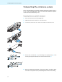
Transporting the conference system .................................................................... 70
Preparing the access point for transport .............................................................. 70
Preparing the conference units for transport ...................................................... 71
Using the transport case .......................................................................................... 72
Integrating WiCOS into a wired conference system ....................................... 73
Connecting the access point to the SDC 8200 CU central unit .........................
Initializing the conference units with the SDC 8200 CU central unit ..............
Configuring the complete conference system - slave mode operation) .........
Using stand-alone operation in parallel with slave mode operation ..............
Holding a conference in slave mode operation ....................................................
Using the interpretation system ............................................................................
73
75
77
78
79
80
Cleaning the conference system ............................................................................. 82
If a problem occurs ... ................................................................................................... 83
Accessories and spare parts ..................................................................................... 84
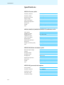
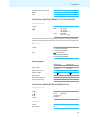
Specifications .................................................................................................................. 85
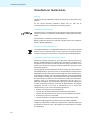
Manufacturer Declarations ........................................................................................ 88
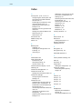
Index .................................................................................................................................. 90
1
Important safety instructions
Important safety instructions
•
Read this instruction manual.
•
Keep this instruction manual. Always include this instruction manual
when passing the products on to third parties.
•
Heed all warnings and follow all instructions in this instruction manual.
•
Refer all servicing to qualified service personnel.
Servicing is required if the products have been damaged in any way,
liquid has been spilled, objects have fallen inside, the products have
been exposed to rain or moisture, do not operate properly or have been
dropped.
•
WARNING: To reduce the risk of fire or electric shock, do not use the
products near water and do not expose them to rain or moisture. Do
not place objects filled with liquids, such as vases or coffee cups, on the
products.
•
Only use the required mains units.
•
Unplug the mains units from the wall socket
– to completely disconnect the devices from the mains,
– during lightning storms or
– when unused for long periods of time.
•
Only operate the mains units from the correct type of power source
(see page 83).
•
Ensure that the mains units are
– in a safe operating condition and easily accessible,
– properly plugged into the wall socket,
– only operated within the permissible temperature range (see
page 84).
– not covered or exposed to direct sunlight for longer periods of time
in order to prevent heat accumulation (see page 84).
•
Do not block any ventilation openings. Install the products in
accordance with the instructions given in this instruction manual.
•
Do not install the products near any heat sources.
•
Only use attachments/accessories specified by Sennheiser.
Overloading
Do not overload wall outlets and extension cables as this may result in fire
and electric shock.
Replacement parts
When replacement parts are required, be sure the service technician uses
replacement parts specified by Sennheiser or those having the same
characteristics as the original part. Unauthorized substitutions may result
in fire, electric shock, or other hazards.
Service and care
No user serviceable parts inside! Do not attempt to service devices yourself
as opening or removing covers may expose dangerous voltage or other
hazards. Refer all servicing to qualified service personnel.
Only use a slightly damp cloth to clean the devices. Do not use any
cleansing agents or solvents.
2
Important safety instructions
Danger due to high volumes
These devices are capable of producing sound pressure exceeding
85 dB(A). 85 dB(A) is the sound pressure corresponding to the maximum
permissible volume which is by law (in some countries) allowed to affect
your hearing for the duration of a working day. It is used as a basis
according to the specifications of industrial medicine. Higher volumes or
longer durations can damage your hearing. At higher volumes, the
duration must be shortened in order to prevent hearing damage. The
following are sure signs that you have been subjected to excessive noise
for too long a time:
•
You can hear ringing or whistling sounds in your ears.
•
You have the impression (even for a short time only) that you can no
longer hear high notes.
Safety instructions for the Lithium-Ion battery pack
If abused or misused, the WiCOS BA battery pack may leak. In extreme
cases, it may even present
•
a heat hazard,
•
a fire hazard,
•
an explosion hazard,
•
a smoke or gas hazard.
Please understand that Sennheiser does not accept liability for damage
arising from abuse or misuse.
Keep away from children.
Do not pack charged batteries
loose – danger of shorting
out/fire hazard.
Observe correct polarity.
Do not short-circuit.
Dispose of the battery pack
at special collection points or
return it to your specialist
dealer.
Switch battery pack-powered
devices off after use.
Only charge the battery pack
with the appropriate
Sennheiser chargers.
When not using the battery
pack for extended periods of
time, charge it regularly
(about every 3 months).
Only charge the battery pack
at ambient temperatures
between 10 °C and 40 °C.
Do not heat above 70 °C/
158 °F, e.g. do not expose to
sunlight or throw into a fire.
Do not mutilate or dismantle.
Do not continue to use a
defective battery pack.
Immediately remove the
battery pack from an
obviously defective device.
When not using the device
for extended periods of time,
remove the battery pack
from the device.
Only use the original
Sennheiser battery pack.
Do not expose to moisture.
3
Important safety instructions
Intended use
Intended use of the WiCOS wireless conference system includes:
•
having read this instruction manual, especially the chapter “Important
safety instructions” on page 2,
•
using the system within the operating conditions and limitations
described in this instruction manual.
“Improper use” means using the system other than as described in this
instruction manual, or under operating conditions which differ from those
described herein.
4
WiCOS – the wireless conference system
WiCOS – the wireless conference system
WiCOS stands for Wireless Conference System – the new generation of
mobile and wireless conference equipment from Sennheiser. The WiCOS
conference system utilizes all advantages of digital communications
technology:
•
Ease of use due to automatic configuration of the system
•
Easy installation and straight-forward operation
•
Conference units with up to 20 hrs operating time
•
Decentralized, clear sound reproduction
•
Conference units are extremely easy to operate
•
Voting function
•
Dynamic frequency management for intermodulation-free operation
•
2 usable frequency bands (2.4 GHz and 5 GHz)
•
Easy integration of the wireless WiCOS system into the wired SDC 8200
digital conference system from Sennheiser
•
Ideal for both small seminars with only a few participants and large
conferences with any number of participants
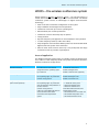
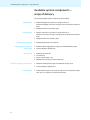
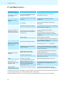
Areas of application
The WiCOS conference system offers you reliable, wireless conferencing on
the 2.4 GHz or 5 GHz frequency bands. The system architecture allows for
different conference configurations:
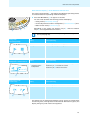
Conference configuration
You can ...
You require ...
Standard operation
• run a discussion with optional
assignment of the “speaking right”
by a chairman
• 1 WiCOS AP access point
• WiCOS D delegate units
• WiCOS C chairman unit (optional)
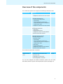
Extended operation
• run a discussion with assignment of
the “speaking right” by a chairman
• conduct voting session
• 1 WiCOS AP access point
• WiCOS DV delegate units
• WiCOS CV chairman unit
integrated operation
(slave mode operation)
• run a discussion with assignment of
the “speaking right” by a chairman
• offer simultaneous interpretation of
the floor channel
• conduct voting sessions
• make use of the additional features
of the Sennheiser SDC 8200
conference and interpretation
system
• WiCOS wireless conference system
– 1 WiCOS AP access point
– WiCOS DV delegate units
– WiCOS CV chairman unit
• wired SDC 8200 conference and
interpretation system
– SDC 8200 CU-M or CU central unit
– SDC 8200 ID interpreter units
– SDC 8200 conference units
5
WiCOS – the wireless conference system
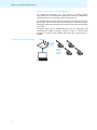
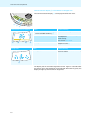
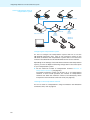
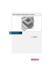
Stand-alone operation – wireless conferencing
For stand-alone operation, you only require the WiCOS system
components. You can use different conference modes and, in addition to
running discussions, you can also conduct voting sessions.
The delegate and chairman units are wirelessly connected to the access
point, which acts as the central unit and controls the conference system.
The battery pack-powered conference units are wireless and can be placed
as you wish.
The access point has an integrated web server for configuring and
monitoring the WiCOS conference system. In order to control these
functions, a computer with network connection and a web browser is
needed.
Setup for stand-alone operation
WiCOS AP
WiCOS CV
WiCOS C
WiCOS DV
WiCOS D
Computer
6
WiCOS – the wireless conference system
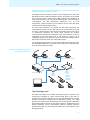
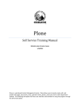
Integrated operation (slave mode operation) – with the wired SDC 8200
conference and interpretation system
The WiCOS wireless conference system can be integrated into the wired
SDC 8200 conference and interpretation system. This allows you to expand
the conference system and/or easily bridge relatively long distances. In
slave mode operation, you can use the WiCOS system for simultaneous
interpretation and add professional accessories such as room
microphones, camera functions or the software control of the SDC 8200
conference and interpretation system.
For slave mode operation, you require the SDC 8200 conference and
interpretation system with the SDC 8200 CU-M or SDC 8200 CU central
unit. One or several access points can be connected to the central unit. As
in stand-alone operation, the access point controls the wireless
communication between the conference units. The conference system is
configured via the SDC 8200 CU-M or SDC 8200 CU central unit. In
integrated operation, all conference units of the wireless WiCOS system
behave like conference units of the SDC 8200 system.
To use language distribution, you also require SDC 8200 interpreter units.
The WiCOS DV and WiCOS CV conference units allow you to select between
up to 16 interpretation channels.
Setup for integrated operation
(slave mode operation)
SDC 8200 conference units
SDC 8200 conference units
WiCOS AP
WiCOS AP
SDC 8200 CU/CU-M
WiCOS CV
WiCOS C
WiCOS DV
WiCOS D
Computer
The technology used
The radio technology of the WiCOS conference system is based on the
transmission standard for radio networks IEEE 802.11 a/g which is
widespread in computer technology. This radio standard offers the largest
possible operational reliability and transmission quality. The radio
protocols are optimized for conferencing, thus avoiding intermodulations
with existing radio networks. The dynamic frequency management of the
WiCOS conference system automatically detects occupied frequency
bands and changes to a free frequency band with no interruptions, even
during operation.
7
Available system components – scope of delivery
Available system components –
scope of delivery
The following WiCOS system components are available:
Delegate unit
1 WiCOS D delegate unit (without voting function) or
WiCOS DV delegate unit (with voting function and channel selection
keys)
1 WiCOS BA Lithium-Ion battery pack
Chairman unit
1 WiCOS C chairman unit (without voting function) or
WiCOS CV chairman unit (with voting function and channel selection
keys)
1 WiCOS BA Lithium-Ion battery pack
Gooseneck microphone
Charging power supply for
battery pack
Access point
1 WiCOS MIC gooseneck microphone
1 WiCOS NT-BA charging power supply for WiCOS BA battery pack
3 country adapters (EU/UK/US)
1 WiCOS AP access point
3 rod antennas
1 network cable (Cat5, 1 m)
1 CD ROM with instruction manual (PDF file)
DC power supply for access point
1 WiCOS NT-AP DC power supply for WiCOS AP access point
3 country adapters (EU/UK/US)
Transport case
8
1 WiCOS CASE transport case (with wheels) for one conference system
with up to 12 conference units and accessories
Overview of the components
Overview of the components
Your conference system can comprise the following conferences units:
Conference unit
Functions
Overview
WiCOS D
Delegate unit for discussions
page 10
• 2 headphone sockets for the floor channel
WiCOS C
Chairman unit with moderator function
page 11
• Next key and priority key
• 2 volume control keys for the
– voting mode
– volume adjustment mode for the
conference units’ built-in loudspeakers
– media control mode
• 2 headphone sockets for the floor channel
WiCOS DV
Delegate unit for discussions including votes page 12
and language distribution
• 3 voting keys
• 2 channel selection keys
• 2 headphones sockets for interpretation
channels and the floor channel
WiCOS CV
Chairman unit with moderator function and
voting administrator function
• Next key and priority key
• 3 operating modes
– voting mode
– volume adjustment mode for the
conference units’ built-in loudspeakers
– media control mode
• 3 voting keys
• 2 channel selection keys
• 2 headphones sockets for interpretation
channels and the floor channel
page 14
The conference system also comprises:
Central unit
Function
Overview
WiCOS AP access
point
• Controls the communication of the
conference units
• Configuration via web server
• Can be integrated in a network
page 18
You can also integrate the WiCOS conference system into the wired
SDC 8200 conference system and interpretation system (see page 73).
9
Overview of the components
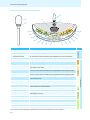
WiCOS wireless conference units
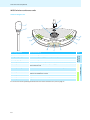
WiCOS D delegate unit
3
1
4
K
2
J
J
I
I
H
H
:
1 Sound inlet basket
for contributing to the discussion
2 Signal light ring
indicates the “speaking right” or a request to speak
3 Coupling ring
locks the microphone
4 Microphone socket
for connection of the microphone, with indentation for correct orientation
0 Microphone LED
indicates a request to speak, the “speaking right” and the connection status of
the conference unit
A Microphone key
switches the conference unit on/off and controls the microphone
H Headphone volume UP
increases the headphone volume
I Headphone volume DOWN
reduces the headphone volume
J Headphone socket
outputs the floor channel to headphones
K Loudspeaker
outputs the floor channel
For an overview of the operating elements at the rear of the conference unit, refer to page 17.
10
Group
Conference unit
Function/Meaning
Gooseneck
microphone
Operating element
Conferencing
A
Sound output
:
Overview of the components
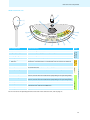
WiCOS C chairman unit
3
1
4
K
2
J
J
5
I
6
H
8
9
Operating element
Function/Meaning
1 Sound inlet basket
for contributing to the discussion
2 Signal light ring
indicates the “speaking right” or a request to speak
3 Coupling ring
locks the microphone
4 Microphone socket
for connection of the microphone, with indentation for correct orientation
5 Priority key
temporarily mutes all conference units or stops the discussion
6 Next key
assigns the “speaking right” to a participant from the request-to-speak list
0 Microphone LED
indicates a request to speak, the “speaking right” and the connection status of
the conference unit
A Microphone key
switches the conference unit on/off and controls the microphone
8 Selection key A
increases the loudspeaker volume on the conference units, stops a voting
session, controls external media devices (depending on the operating mode)
9 Selection key B
reduces the loudspeaker volume on the conference units, starts a voting
session, controls external media devices (depending on the operating mode)
H Headphone volume UP
increases the headphone volume
I Headphone volume DOWN
reduces the headphone volume
J Headphone socket
outputs the floor channel to headphones
K Loudspeaker
outputs the floor channel
Group
Conference unit
:
Conferencing Chairman Gooseneck
functions microphone
A
Sound output
:
For an overview of the operating elements at the rear of the conference unit, refer to page 17.
11
Overview of the components
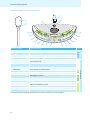
WiCOS DV delegate unit with voting function
3
1
4
K
2
J
J
I
H
H
I
C
B
E
G
Operating element
Function/Meaning
1 Sound inlet basket
for contributing to the discussion
2 Signal light ring
indicates the “speaking right” or a request to speak
3 Coupling ring
locks the microphone
4 Microphone socket
for connection of the microphone, with indentation for correct orientation
0 Microphone LED
indicates a request to speak, the “speaking right” and the connection status of
the conference unit
A Microphone key
switches the conference unit on/off and controls the microphone
B NO key
votes “no” in a voting session
C ABSTAIN key
votes “abstain” in a voting session
D YES key
votes “yes” in a voting session
E Channel selection display
displays the interpretation channel, the voting results and
the headphone volume
F CHANNEL UP key
selects the next interpretation channel
G CHANNEL DOWN key
selects the previous interpretation channel
H Headphone volume UP
increases the headphone volume
I Headphone volume DOWN
reduces the headphone volume
J Headphone socket
outputs the floor channel and the interpretation channels to headphones
K Loudspeaker
outputs the floor channel
For an overview of the operating elements at the rear of the conference unit, refer to page 17.
12
Group
Conference unit
D
F
:
Conferencing Gooseneck
microphone
E
A
Voting
keys
:
Language
distribution
F
Sound output
G
Overview of the components
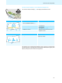
Channel selection display E of the WiCOS DV delegate unit
The channel selection display E can display two different views.
E
G
F
Interpretation channel selection
Display
Function/Meaning
Q Direction of the CHANNEL UP key F selects the next or the previous channel
and the CHANNEL DOWN key G
Q
R
Voting result
S
Q
R Channel number and channel name
displays the current channel output via
the headphones
Default setting:
floor channel “00 FLOOR”
S Headphone volume
displays the adjusted volume on the
headphone socket
Display
Function/Meaning
T Voting result
displays the voting result after the voting
session has ended
T
The display has an automatic brightness control. Approx. 4 seconds after
the last key press, the brightness will be reduced. With each key press, the
display will light up with maximum brightness.
13
Overview of the components
WiCOS CV chairman unit with voting function
3
1
4
K
2
J
J
I
5
H
6
B
9
Operating element
Function/Meaning
1 Sound inlet basket
for contributing to the discussion
2 Signal light ring
indicates the “speaking right” or a request to speak
3 Coupling ring
locks the microphone
4 Microphone socket
for connection of the microphone, with indentation for correct orientation
5 Priority key
temporarily mutes all conference units or stops the discussion
6 Next key
assigns the “speaking right” to a participant from the request-to-speak list
7 Multi-function display
displays the voting mode, the loudspeaker mode of the conference units and
the media control mode
8 Selection key A
increases the loudspeaker volume on the conference units, stops a voting
session, controls external media devices (depending on the operating mode)
9 Selection key B
reduces the loudspeaker volume on the conference units, starts a voting
session, controls external media devices (depending on the operating mode)
0 Microphone LED
indicates a request to speak, the “speaking right” and the connection status of
the conference unit
A Microphone key
switches the conference unit on/off and controls the microphone
B NO key
votes “no” in a voting session
C ABSTAIN key
votes “abstain” in a voting session
D YES key
votes “yes” in a voting session
E Channel selection display
displays the interpretation channel, the voting results and
the headphone volume
F CHANNEL UP key
selects the next interpretation channel
G CHANNEL DOWN key
selects the previous interpretation channel
H Headphone volume UP
increases the headphone volume
I Headphone volume DOWN
reduces the headphone volume
J Headphone socket
outputs the floor channel and the interpretation channels to headphones
K Loudspeaker
outputs the floor channel
For an overview of the operating elements at the rear of the conference unit, refer to page 17.
14
Group
Conference unit
C
8
Chairman Gooseneck
functions microphone
D
7
:
Conferencing Voting and media
functions
E
A
Voting
keys
:
Language
distribution
F
Sound output
G
Overview of the components
Multi-function display 7 of the WiCOS CV chairman unit
The multi-function display 7 can display three different operating modes.
To switch between the operating modes and displays:
왘 Press the ABSTAIN key C for approx. 3 seconds.
You can switch between the following modes and displays:
– Voting mode (“Start/Stop Voting”)
– Volume adjustment mode for loudspeakers (“Volume Control”) and
– Media control mode (“Function key”).
7
Depending on the mode, the selection key A 8 and the selection
key B 9 are assigned different functions.
8
9
C
You can also switch between the operating modes using the web
server (see page 65).
Voting mode
“Start/Stop Voting”
Display
Function/Meaning
L Start
Selection key B 9 starts a voting session
M Stop
Selection key A 8 stops a voting session
Display
Function/Meaning
N Volume of the
Adjusted volume of the conference units’ loudspeakers K
M
L
Volume adjustment mode for
loudspeakers “Volume Control”
conference units’
loudspeakers
Selection key A 8 increases the volume
Selection key B 9 reduces the volume
N
Media control mode
“Function key”
O
Display
Function/Meaning
O Media control 1
Selection key A 8 controls external media devices
P Media control 2
Selection key B 9 controls external media devices
P
The display has an automatic brightness control. Approx. 4 seconds after
the last key press, the brightness will be reduced. With each key press, the
display will light up with maximum brightness.
15
Overview of the components
Channel selection display E of the WiCOS CV delegate unit
The channel selection display E can display two different views.
E
G
F
Interpretation channel selection
Display
Function/Meaning
Q Direction of the CHANNEL UP key F selects the next or the previous channel
and the CHANNEL DOWN key G
Q
R
Voting result
S
Q
R Channel number and channel name
displays the current channel output via
the headphones
Default setting:
floor channel “00 FLOOR”
S Headphone volume
displays the adjusted volume on the
headphone socket J
Display
Function/Meaning
T Voting result
displays the voting result after the voting
session has ended
T
The display has an automatic brightness control. Approx. 4 seconds after
the last key press, the brightness will be reduced. With each key press, the
display will light up with maximum brightness.
16
Overview of the components
Rear of the conference console
U
V
W
Operating element
Function/Meaning
U RF link indicator
displays the connection status with the access point
V Battery pack connection
for connection to the WiCOS BA battery pack
W Battery guide rails
ensure correct insertion of the WiCOS BA battery pack
WiCOS BA Lithium-Ion battery pack
Y
X
[
Z
\
]
Operating element
Function/Meaning
X Socket for charging power
for connection of the charging power supply, charges the battery pack and allows
mains operation
supply
Y Status indicator
displays the charging process and mains operation
Z Charge status indicator
displays the charge status and the status of the charging electronics
[ Key
activates the charge status indicator Z and the charging electronics indicator
\ Contacts
for connecting the battery pack to the conference unit
] Battery release clip
secures the battery pack against inadvertent detachment from the conference unit
17
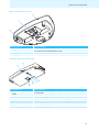
Overview of the components
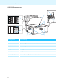
WiCOS AP access point
a
^
b
c
d
d
f
e
f
95 mm
g
f
h
i
f
jk l m
Operating element
Function/Meaning
^ Status indicators
displays the operating mode, the connection status and the RF signal quality
a Antennas
transmit and receive RF signals, adjustable
b Reset key
resets the access point to the factory default settings
c Antenna coupling ring
locks the antennas
d Eyelets for wall mounting
for mounting the access point to a wall
e Antenna sockets
for connection of the antennas
f Rubber feet
ensure that the access point cannot slip on the surface on which it is placed
g Stand mount
for mounting the access point to a stand with 5/8” mounting stud
h Network socket (RJ 45)
for connection to a network or computer to configure and monitor the conference
system via the web server
i Cable grip
ensures that the cable cannot slip out of the socket for DC power supply
j IN system socket (RJ 45)
for connection of the SDC 8200 conference and interpretation system
k OUT system socket (RJ 45)
for connection of additional access points
l Socket for DC power supply
for connection of the WiCOS NT-AP DC power supply
m On/off switch
switches the access point on/off
18
Overview of the components
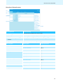
Overview of the web server
n
o
p
q
r
Operating element
Function/Meaning
n Main navigation
Tabs of the main navigation level, always visible
o Subnavigation
Second navigation level, depending on the main navigation
p Structure of the current category
Different topics and categories of the current configuration page
q Overview and configuration
Selection possibilities and/or listing of the current configurations contents
contents
r Help on the current category
Explanations on the current configuration page
Main navigation
Subnavigation
Detailed information
“Setup”
“Summary”
page 49
“TCP/IP settings”
page 49
“Country Selection”
page 51
“Admin”
page 52
“General”
page 53
“Quality 2.4 GHz ISM”
page 56
“Quality 5.15-5.35 GHz”
page 56
“Quality 5.47-5.725 GHz”
page 56
“Quality 5.8 GHz ISM”
page 56
“General”
page 58
“Unit Monitoring”
page 62
“Init Units”
page 63
“Chairman Config”
page 65
“Logging”
page 66
“Update”
page 67
“Key assignment”
page 68
”RF Configuration”
“Conference Management”
“Service”
“Encryption”
19
Overview of the components
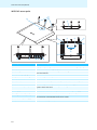
WiCOS CASE transport case
u
t
s
w
|
{
z
y
Operating element
Function/Meaning
s Microphone holder
holds up to 12 gooseneck microphones
t Lid
separates the upper and lower shell of the case
u Telescopic handle
for pulling the transport case on its wheels
v Catch
locks the telescopic handle
w Lock
locks the transport case, can be locked with U-locks
x Carrying handle
for carrying the transport case
y Wheels
for easy transportation
z Conference unit holder
holds up to 12 conference units with inserted battery packs
{ Accessory compartment stores mains power supplies, accessories, cables, etc.
| Access point holder
20
holds an access point
x
v
Putting the conference system into operation
Putting the conference system into
operation
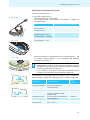
Putting the access point into operation
The access point controls the wireless communication between the
individual conference units.
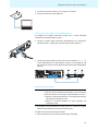
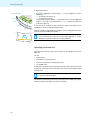
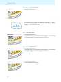
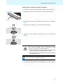
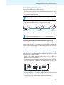
Connecting the antennas
The supplied rod antennas are mounted quickly and easily. They ensure
reliable radio transmission within buildings. The transmission range is
approx. 30 m. Always connect all 3 antennas to ensure reliable radio
communication.
CAUTION! Radio communication outside the legal requirements!
When connecting antennas other than the supplied ones, the
transmission power of the conference system may not meet
the legal requirements.
왘 Only connect the supplied antennas to the access point.
왘 Connect the 3 antennas a to the antenna sockets e.
e
e
a
e
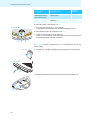
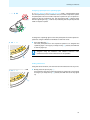
왘 Screw down the 3 antenna coupling rings c as shown.
The antennas are locked.
c
c
a
c
Connecting the access point to the mains
When connecting the access point via a system cable to the
SDC 8200 CU-M or SDC 8200 CU central unit of the SDC 8200
conference and interpretation system, you do not require the
WiCOS NT-AP DC power supply.
CAUTION! Danger due to electric current!
If you use an unsuitable power supply, this can cause damage
to the access point.
왘 Only connect the WiCOS NT-AP DC power supply to the
access point.
21
Putting the conference system into operation
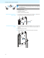
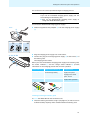
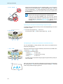
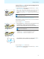
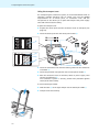
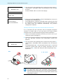
왘 Connect the DC power supply } to the socket l.
l
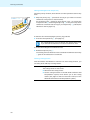
왘 Pass the cable of the DC power supply through the cable grip i as
shown.
i
왘 Slide the supplied country adapter ~ onto the DC power supply }.
NT-AP
왘 Plug the DC power supply into a wall socket.
}
~
EU
UK
US
Connecting the access point to a computer/network
In order to change the configuration of the access point or to monitor the
conference system, you require a computer with network connection (RJ
45) and a web browser.
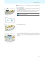
왘 Connect the supplied network cable (Cat5) to the network socket
(RJ 45) h.
h
22
Putting the conference system into operation
왘 Connect the network cable to your computer or network.
왘 Call up the web server (see page 45).
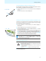
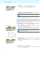
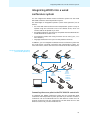
Connecting a system cable for integrated operation
To integrate the WiCOS conference system into a wired SDC 8200
conference and interpretation system:
j
왘 Connect a system cable (Sennheiser SDC CBL RJ45, see “Accessories
and spare parts” on page 83) to the IN system socket (RJ 45) j.
왘 Connect the system cable to one of the six RJ 45 sockets (“PORT 1-6”)
of the SDC 8200 CU-M or SDC 8200 CU central unit (see page 70 and
the instruction manual of the SDC 8200 conference and interpretation
system).
j
SDC 8200 CU
PORT 1-6
Accesspoint
WiCOS AP
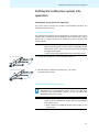
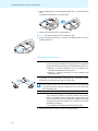
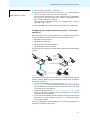
Setting up the access point
CAUTION! Danger of intermodulation!
If you set up the individual components of the conference
system too close to one another, intermodulation can occur.
왘 Observe a minimum distance of 1.5 m between the access
point and the conference units.
왘 Observe a minimum distance of 50 cm between the
conference units.
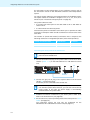
왘 If possible, set up the devices so that there is a “free line of sight”
between the conference units and the access point.
To obtain the optimum transmission range:
왘 Place the access point as centrally and as high as possible.
23
Putting the conference system into operation
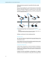
30 m
The transmission range of the conference units and the access
point is approx. 30 m. The transmission range can vary depending
on location and environmental conditions such as wall thickness,
wall composition etc.
30 m
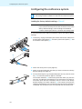
The access point can be
Mounting the access point to a
wall or ceiling
•
mounted to a wall or ceiling or
•
mounted on a stand or
•
placed on a flat surface (e.g. table),
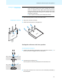
왘 Use suitable screws and the eyelets for wall mounting d at the rear of
the access point to mount the access point to a wall.
d
95 mm
d
Mounting the access point on
a stand
왘 Use a stand with 5/8” mounting stud (adapter to 3/8” mounting stud
available as optional accessory, see “Accessories and spare parts” on
page 83).
왘 Adjust the legs of the stand.
왘 Use the stand mount g to screw the access point on the stand.
5/8'' g
24
Putting the conference system into operation
Placing the access point on
a flat surface
CAUTION! Risk of staining of furniture surfaces!
Some furniture surfaces have been treated with varnish,
polish or synthetics which might cause stains when they
come into contact with other synthetics. Despite a thorough
testing of the synthetics used by us, we cannot rule out the
possibility of staining.
왘 Do not place the access point on delicate surfaces.
왘 Place the access point on a flat, horizontal surface.
Aligning the antennas
왘 Align the 3 antennas vertically.
왘 Switch the access point on (see page 29).
Putting the conference units into operation
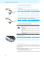
Connecting the microphone
왘 Connect the gooseneck microphone to the microphone socket 4 so
that the protrusion engages with the indentation.
4
왘 Screw down the coupling ring 3.
The microphone is securely connected to the conference unit.
3
왘 Set up the conference unit so that it can be comfortably operated by
the participant.
25
Putting the conference system into operation
왘 Tilt the microphone toward the participant.
Checking the charge status of the battery pack
왘 Press the key [.
The charge status indicator Z displays the current charge status:
Z
[
LED Z lights up
Remaining capacity
Remaining operating time
1
red
0-20 %
approx. 4 hours
2
orange
20-40 %
approx. 4-8 hours
3
orange
40-60 %
approx. 8-12 hours
4
green
60-80 %
approx. 12-16 hours
5
green
80-100 %
approx. 16-20 hours
The charge status indicator Z goes of after approx. 5 seconds. The
LED 3 then display the status of the charging electronics.
Z
LED Z
flashes
Charging electronics
3
orange
functions properly
3
–
defective
The LED 3 goes off after approx. 7 seconds.
CAUTION! Danger of burns and damage to the device!
A defective battery pack can ignite and destroy the
conference unit!
왘 Disconnect the charging power supply from the defective
battery pack.
왘 Remove the defective battery pack from the conference
unit.
왘 Dispose of the defective battery pack in accordance with
the regulations.
C CV D DV
When the battery pack is almost flat, the status indicator U indicates the
remaining operating time.
Red LED U flashes approx. ... per second
Remaining operating time
once
approx. 4 hours
twice
approx. 2 hours
four times
approx. 1 hour
U
Charging the battery pack
The WiCOS BA Lithium-Ion battery pack is pre-charged upon delivery, i.e.
you can immediately use the conference unit without having to charge the
battery pack first.
There are two ways to charge the battery pack, both using the
WiCOS NT-BA charging power supply:
26
•
You can charge the battery pack separately.
•
You can charge the battery pack when it is inserted into the conference
unit.
Putting the conference system into operation
The conference unit can be operated during the charging process.
CAUTION! Danger due to electric current!
If you use an unsuitable charging power supply, this can
cause damage to the battery pack.
왘 Only use the WiCOS NT-BA charging power supply to
charge the WiCOS BA battery pack.
To connect the WiCOS NT-BA charging power supply:
왘 Slide the supplied country adapter ~ onto the charging power supply
}.
NT-BA
}
~
EU
UK
C CV D DV
X
US
왘 Plug the charging power supply into a wall socket.
왘 Connect the plug of the charging power supply } to the socket X of
the battery pack.
The charging process starts.
When you have connected the charging power supply to the battery pack,
the status indicator Y and the charge status indicator Z provide
information on the charging process and on mains operation:
Status indicator Y Charge status indicator Z
Charging process
green and yellow
lights up (indicating the
current charge status)
the battery pack is being
charged, a complete
charging process takes
approx. 4 hours
green
off
the battery pack is fully
charged, mains operation
Y
Z
Inserting/removing the battery pack
To insert the WiCOS BA into the conference unit:
왘 Check the battery pack before using it (see page 26) in order to ensure
sufficient battery capacity and to exclude a defective battery pack.
27
Putting the conference system into operation
왘 Slide the battery pack into the battery guide rails W of the conference
unit.
The battery release clip ] locks into place.
]
W
왘 Switch the conference unit on (see page 31).
To remove the battery pack from the conference unit:
왘 Press the battery release clip ] and pull the battery pack out of the
battery guide rails.
]
Setting up the conference units
CAUTION! Danger of intermodulation!
If you set up the individual components of the conference
system too close to one another, intermodulation can occur.
왘 Observe a minimum distance of 1.5 m between the
conference units and the access point.
왘 Observe a minimum distance of 50 cm between the
conference units.
왘 If possible, set up the devices so that there is a “free line of sight”
between the conference units and the access point.
30 m
30 m
The transmission range of the conference units and the access
point is approx. 30 m. The transmission range can vary depending
on location and environmental conditions such as wall thickness,
wall composition etc.
CAUTION! Risk of staining of furniture surfaces!
Some furniture surfaces have been treated with varnish,
polish or synthetics which might cause stains when they
come into contact with other synthetics. Despite a thorough
testing of the synthetics used by us, we cannot rule out the
possibility of staining.
왘 Do not place the access point on delicate surfaces.
왘 Place the conference units on a flat, horizontal surface.
28
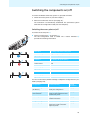
Switching the components on/off
Switching the components on/off
To switch the WiCOS conference system on, proceed as follows:
1. Switch the access point on (see next chapter).
2. Switch the conference units on (see page 31).
The connection is automatically established. The conference system
loads the last configuration used (see next chapters).
Switching the access point on/off
To switch the access point on:
m
`
^
^
왘 Set the on/off switch m to position “1”.
The last configuration used is loaded. The 3 status indicators ^
provide the following information:
Blue LED 1
Operating mode of the access point
flashes slowly
integrated operation (slave mode)
lights up
stand-alone operation
Red LED 2
Link quality (RF signal quality)
off
excellent
flashes slowly
good
flashes rapidly
fair
lights up
low
Blue LED 3
Connection status with the conference units
flashes rapidly
no connection
lights up
connection with at least 1 conference unit
You can use the factory default settings or adapt the configuration to your
needs (see page 44):
Detailed
information
Configuration
Function/Meaning
Network settings
(IP address)
To load the web server and to
modify the configuration
see page 49
Country settings for radio
communication
To set country-specific limit
values for radio frequencies and
transmission power
see page 51
Password protection
To protect the web server from
unauthorized access
see page 52
RF signal strength
To set the transmission power
see page 53
Radio frequency
To set the radio frequencies to be see page 53
used in the 2.4 GHz and 5 GHz
frequency bands
29
Switching the components on/off
Function/Meaning
Max. number of
simultaneously active
microphones
To set the max. number of
simultaneously active
microphones in a discussion
see page 57
Conference mode
To set the conference mode
see page 58
Loudspeaker volume
To set the volume of the
conference units’ loudspeakers
see page 59
Number of interpretation
channels
To set the number of the
interpretation channels
see page 60
Operating mode of the
chairman units
To set the function of the
selection key A 8 and B 9
see page 65
Operating mode of the
access point
To set the access point to standalone operation or integrated
operation (slave mode) with
SDC 8200
see page 61
Initialization mode of the
conference units
To initialize the conference units
on the access point
see page 57
Encryption mode
To set the encryption mode for
radio transmission
see page 67
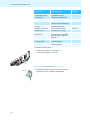
To switch the access point off:
왘 Set the on/off switch m to position “0”.
The 3 status indicators ^ go off.
m
To disconnect the access point from the mains:
NT-AP
30
Detailed
information
Configuration
왘 Unplug the DC power supply from the wall socket.
The access point is completely switched off.
Switching the components on/off
Switching a conference unit on/off
To switch a conference unit on :
왘 Press the microphone key A.
The last configuration used is loaded.
The microphone LED 0 and the RF link indicator U display the
connection status:
C CV D DV
V
LED
Connection status with the access point
off:
connection is established
RF link indicator U,
microphone LED 0
:
flashes:
connection is being established
RF link indicator U: blue
:
microphone LED 0: red green
A
lights up:
C CV D DV
malfunction
RF link indicator U: blue
U
When the connection is established, the multi-function display 7 and
the channel selection display E of the WiCOS DV and WiCOS CV
conference units switch on.
C CV D DV
If there are several access points within the transmission range,
intermodulation can occur. In this case, use the dynamic frequency
management (see page 53) and initialize the desired conference
units on the access point (see page 76).
E
E
C CV D DV
7
If no connection to an access point can be established within
2 minutes, the conference unit automatically switches off.
The following last used configurations are loaded. You can use the factory
default settings or adapt the configuration to your needs (see page 44):
Detailed
information
Configuration
Function/Meaning
Country settings for
radio communication
To set country-specific limit values
for radio frequencies and
transmission power
see page 51
RF signal strength
To set the transmission power
see page 53
Radio frequency
To set the radio frequencies to be
used in the 2.4 GHz and 5 GHz
frequency bands
see page 53
Loudspeaker volume
To set the volume of the conference
units’ loudspeakers
see page 59
7
Operating mode of the To set the function of the selection
chairman units
key A 8 and B 9
see page 65
31
Switching the components on/off
Detailed
information
Configuration
Function/Meaning
Setting the
initialization mode of
the conference units
To initialize the conference units on
the access point
see page 57
Encryption mode
To set the encryption mode for radio
transmission
see page 67
To manually switch a conference unit off:
왘 Press the microphone key A for 3 seconds.
The conference unit switches off. All LEDs and displays go off.
C CV D DV
To automatically switch all conference units off:
3s
:
A
왘 Switch the access point off (see page 29).
If there is no connection to an access point, the conference units will
automatically switch off after 2 minutes.
:
To completely switch a conference unit off and disconnect it from the
power supply:
NT-BA
왘 If necessary, unplug the charging power supply from the wall socket.
C CV D DV
X
왘 Remove the battery pack from the conference unit (see page 27).
]
32
Running a conference
Running a conference
The character of your conference (i.e. the conditions under which the
participants can take the floor, are assigned the “speaking right” or can
listen to simultaneous interpretations) depends on the settings of the
access point. You can adapt the conference system to your individual
needs or use the factory default settings (see page 44).
Operating a delegate unit
The WiCOS D and WiCOS DV delegate units feature two headphone outputs
and can therefore be used by one or two participants.
Taking the floor/Making a request to speak
Depending on the conference mode set (see page 58), you can
•
take the floor immediately or
•
make a request to speak.
You then have to wait until the chairman switches on your microphone.
If the conference mode is set so that you can take the floor immediately
(“Direct Access” (factory default setting), “FIFO”, “Override”, “Group 1-4”,
see page 58):
왘 Press the microphone key A.
Your microphone switches on and you can take the floor immediately.
The microphone LED 0 and the signal light ring 2 light up red. The
loudspeaker K is muted. Depending on the conference mode and the
speaker limit set, the microphone of the previous speaker will be
switched off.
C CV D DV
:
C CV D DV
If the conference mode is set so that you first have to make a request to
speak (“With request”, “With request no clear”, see page 58):
:
A
왘 Press the microphone key A.
Your request to speak is added to the request-to-speak list. The
microphone LED 0 flashes green and the signal light ring 2 flashes
red.
2
K
:
:
33
Running a conference
C CV D DV
When the chairman assigns you the “speaking right”, your microphone
switches on. The microphone LED 0 and the signal light ring 2 light up
red. The loudspeaker K is muted. Depending on the conference mode
and the speaker limit set, the microphone of the previous speaker will
be switched off.
2
K
With a chairman unit, you can take the floor at any time,
without first having to be assigned the “speaking right”.
:
:
If you are only using delegate units, you can only choose
conference modes where the “speaking right” does not have to
be assigned by a chairman (“Direct Access” (factory default
setting), “FIFO”, “Override”, “Group 1-4”, see page 58).
Switching the microphone off/Cancelling a request to speak
To switch off the microphone when you have finished speaking or to cancel
a request to speak:
왘 Press the microphone key A once more.
The microphone LED 0 and the signal light ring 2 go off.
C CV D DV
:
A
:
Participating in a voting session (WiCOS CV and WiCOS DV only)
You can participate in voting sessions which have to be started by the
chairman (see page 38).
After the voting session has been started by the chairman, the LEDs of the
voting keys B, C and D flash.
C CV D DV
왘 Press the corresponding key:
– YES key D:
to vote “yes”
– ABSTAIN key C: to abstain from voting
– NO key B:
to vote “no”
The LED next to the pressed voting key lights up permanently and your
vote is counted.
D
C
B
After the voting session has been stopped by the chairman (see page 38)
the voting result T is shown on the channel selection display E. The LED
next to the pressed voting key goes off.
E
T
34
Running a conference
Connecting headphones (WiCOS CV and WiCOS DV only)
You can listen to the floor channel or the offered interpretation channels
(where applies) via headphones (see next section).
C CV D DV
J
왘 Connect headphones with a 3.5 mm jack plug to one of the headphone
sockets J.
You can connect mono or stereo headphones.
J
Listening to simultaneous interpretation (WiCOS CV and WiCOS DV only)
In order for you to be able to listen to a simultaneous interpretation of the
floor channel via headphones, the conference system has to be connected
to an interpretation system (see page 73).
왘 Ask the organizer on which channel your desired language is
transmitted.
왘 Connect headphones to your conference unit (see above).
C CV D DV
왘 Press the CHANNEL UP key F or the CHANNEL DOWN key G to select
the desired interpretation channel.
The selected interpretation channel is output via your headphones. The
channel selection display E shows the currently set channel, e.g. “07
ENG” for channel 07 with interpretation into English (depending of the
configuration of the interpretation system). If you select “00 FLOOR”,
the floor channel will be output (factory default setting).
E
G
F
If the channel selection display E is showing a voting result, you
can return to the channel display view by pressing the
CHANNEL UP key F or the CHANNEL DOWN key G. The voting
result cannot be displayed again.
Adjusting the headphone volume
CAUTION! Hearing damage due to high volumes!
Listening at high volume levels for long periods can lead to
permanent hearing defects.
왘 Before putting the headphones on, set the volume to a
minimum level.
왘 Do not continuously expose yourself to high volumes.
왘 Put the headphones on.
35
Running a conference
To adjust the volume:
왘 Press the headphone volume UP key H or the headphone volume
DOWN key I:
“+” to increase the volume or
“–” to reduce the volume.
The channel selection display E shows the volume on the headphone
output S. As long as you keep the key H or I pressed, the LED next
to the key lights up.
C CV D DV
J
I
H
If you switch the conference units off and on again (see page 31), the
headphone volume is reset to a medium level.
E
With the WiCOS CV and WiCOS C conference units, the adjusted volume is
common for both headphone sockets J.
E
The volume of the conference units’ loudspeakers can be adjusted
via the web server of the access point (see page 59) or via the
WiCOS CV or WiCOS C chairman unit (see page 41).
S
Operating a chairman unit
The chairman units have the same functions as the delegate units (see
page 33).
You can
•
take the floor,
•
participate in a voting session,
•
listen to simultaneous interpretations and
•
use headphones.
A chairman unit allows you to take the floor at any time without having to
“apply” for a comment. Active chairman units are not counted against the
speaker limit.
In a conference system with several chairman units, all chairman
units have the same rights.
The WiCOS C and WiCOS CV chairman units feature two headphone outputs
and can therefore be used by one or two chairmen.
36
Running a conference
Assigning a participant the “speaking right”
C CV D DV
2
If – in “With Request” or “With Req. No Clear” mode – a participant presses
the microphone key on his conference unit, he makes a request to speak.
All participants who have made a request to speak will join a request-tospeak list. On the conference unit, the microphone LED 0 flashes green
and the signal light ring 2 flashes red, indicating that the participant has
made a request to speak.
:
:
To assign the “speaking right” to the next participant from the request-tospeak list using the WiCOS C and WiCOS CV chairman units:
왘 Press the NEXT key 6.
The next participant from the request-to-speak list is assigned the
“speaking right”. As long as you keep the key 6 pressed, the LED next
to the key lights up.
C CV D DV
In stand-alone operation, the “speaking right” can only be
assigned using the WiCOS CV and WiCOS C chairman units.
Conference control via the web server is not possible.
6
Ending a discussion
Using the cancel function, the chairman can end a discussion at any time.
왘 Briefly press the priority key 5.
All conference units are muted. The request-to-speak list is not cleared.
As long as you keep the key 5 pressed, the LED next to the key lights
up.
C CV D DV
5
37
Running a conference
Muting all delegate units temporarily
Using the priority function, the chairman can interrupt a discussion at any
time.
왘 Keep the priority key 5 pressed for as long as you want to mute the
conference units (push-to-mute function).
All conference units – except for the chairman units – are muted. The
microphone LED 0 and the signal light ring 2 of the previously active
conference units flash red. As long as you keep the key 5 pressed, the
LED next to the key lights up.
C CV D DV
5
To take the floor while keeping the priority key pressed:
왘 Press the microphone key A (see page 33).
The “speaking right” of your chairman unit remains active, even
if you cancel the conference or mute the conference units.
To cancel the muting of the conference units:
왘 Release the priority key 5.
The muting of the conference units is canceled. The LED next to the key
5 goes off. The discussion is continued.
Starting a voting session
With the WiCOS C and WiCOS CV chairman unit with voting function, you
can start, pause and stop a voting session.
CAUTION! Danger of loss of the voting result!
The voting results are not saved.
왘 Note down the voting results.
왘 Use the voting functions of the SDC 8200 conference and
interpretation system, which allows you to save voting
results (see page 73 and the instruction manual of the
SDC 8200 conference and interpretation system).
38
Running a conference
If you are using the WiCOS CV chairman unit, you have to proceed as
follows.
To start a voting session:
왘 Keep the ABSTAIN key C pressed until the “voting mode” is shown on
the multi-function display 7.
The multi-function display switches between “voting mode”, “volume
adjustment mode for loudspeakers” and “media control mode”.
C CV D DV
7
You can also switch between the operating modes using the
web server (see page 65).
C
7
왘 Press the selection key B 9.
C CV D DV
9
With the WiCOS DV and WiCOS CV conference units, the LEDs next to
the keys B, C and D light up. The participants can cast their vote (see
page 34).
C CV D DV
D
C
B
39
Running a conference
To end or cancel the voting session:
왘 Press the selection key A 8.
C CV D DV
8
The voting session is stopped. The LEDs next to the keys B, C and D
go off. The voting result T is shown on the channel selection
displays E of the conference units.
E
T
To clear the voting result:
왘 Press the selection key A 8.
The voting result T on the channel selection display E is cleared and
the display changes to the interpretation channel view.
C CV D DV
8
To start a new voting session:
왘 Press the selection key A 8.
The voting result T on the channel selection display E is cleared and
the display changes to the interpretation channel view.
C CV D DV
8
왘 Press the selection key B 9.
A new voting session is started.
C CV D DV
9
40
Running a conference
If you are using the WiCOS C chairman unit, the set operating mode of the
conference unit and the voting result cannot be displayed. You can
nevertheless conduct voting session.
왘 Via the web server, set the function of the selection key A 8 and B 9
to “Start/Stop Voting” (see page 65).
왘 Start or stop voting session and delete voting results using the
selection key A 8 and B 9 (for more information, see page 38).
As long as you keep the key 8 or 9 pressed, the LEDs next to the keys
light up.
C CV D DV
With the WiCOS C chairman unit, you cannot participate in the
voting session yourself.
8
9
Setting the volume of the conference units’ loudspeakers
With the WiCOS CV or WiCOS C chairman units, you can set the loudspeaker
volume of all conference units.
If you are using the WiCOS CV chairman unit:
왘 Keep the ABSTAIN key C pressed until the “volume adjustment mode
for loudspeakers” is shown on the multi-function display 7.
The multi-function display switches between “voting mode”, “volume
adjustment mode for loudspeakers” and “media control mode”.
CCVCV D DV
You can also switch between the operating modes using the
web server (see page 65).
7
C
왘 Press the
C CV D DV
– selection key A 8 to increase the loudspeaker volume or
– selection key B 9 to reduce the loudspeaker volume.
9 8
7
The loudspeaker volume is changed. The multi-function display 7
shows the volume of the conference units’ loudspeakers N.
7
N
If you are using the WiCOS C chairman unit:
왘 Via the web server, set the function of the selection key A 8 and B 9
to “Volume Control” (see page 65)
41
Running a conference
왘 Press the
C CV D DV
– selection key A 8 to increase the loudspeaker volume or
– selection key B 9 to reduce the loudspeaker volume.
9
8
The loudspeaker volume is changed. As long as you keep the key 8 or
9 pressed, the LED next to the key lights up.
The volume of the conference units’ loudspeakers can also be
adjusted via the web server of the access point (see page 59).
Activating the media control mode
In the future, the WiCOS C and WiCOS CV chairman units will allow you to
transmit commands to a media control system, for example in order to
trigger circuits via a home controller. The corresponding commands can be
programmed via the web server of the access point.
If you are using the WiCOS CV chairman unit, activate the media control
mode as follows (e.g. to start or stop a camera system):
왘 Keep the ABSTAIN key C pressed until the “media control mode” is
shown on the multi-function display 7.
The multi-function display switches between “voting mode”, “volume
adjustment mode for loudspeakers” and “media control mode”.
C CV D DV
7
C
You can also switch between the operating modes using the
web server (see page 65).
7
왘 Press the selection key A 8 or the selection key B 9 to trigger circuits
via a home controller.
Depending on the setting, pressing key 8 or 9 transmits a start signal
or a stop signal.
C CV D DV
9
8
If you are using the WiCOS C chairman unit:
왘 Via the web server, set the function of the selection key A 8 and B 9
to “Function key” (see page 65).
42
Running a conference
왘 Press the selection key A 8 or the selection key B 9 to trigger circuits
via a home controller.
Depending on the setting, pressing key 8 or 9 transmits a start signal
or a stop signal. As long as you keep the key 8 or 9 pressed, the LED
next to the key lights up.
C CV D DV
9
8
43
Configuring the conference system
Configuring the conference system
If you change the factory default settings via the web server, the
last settings used are loaded on a restart of the conference system.
Loading the factory default settings – “Reset“
CAUTION! Loss of settings!
If you reset the access point and the conference units to the
factory default settings, custom settings are discarded.
왘 Before resetting the devices, note down the settings used.
To reset the access point and the conference units to the factory default
settings:
k
j
왘 If necessary, unplug connected system cables and network cables from
the IN system socket (RJ 45) j, the OUT system socket (RJ 45) k and
the network socket (RJ 45) h.
h
왘 Switch the access point on (see page 29).
왘 Switch on all the conference units that you want to reset to the factory
default settings (see page 31).
b
44
왘 Use a pointed object (e.g. straightened paper clip) to press the reset
key b on the access point for approx. 5 seconds.
The 3 status indicators ^ of the access point flash while you press the
reset key. All indicators and displays on the conference units light up.
The access point and the conference units are reset to the factory
default settings. The status indicators ^ of the access point and the
indicators and displays on the conference units go off once resetting is
completed. The conference units are initialized with the access point.
Configuring the conference system
After the reset, the following factory default settings are loaded:
Configuration
Factory default setting
Network settings
(IP address)
System name: “WiCOS“
IP address mode: “Static“
IP: “192.168.0.10“
Subnet: “255.255.255.0“
Password protection
“123“
RF signal strength (“Room size“)
“Big“
Radio frequency
“Automatically“
Country settings for radio communication “US/Canada“
(“Country selection“)
Max. number of simultaneously
active microphones
“4“
Conference mode
“Direct Access“
Loudspeaker volume
“6“
Number of interpretation channels
“0“
Operating mode of the chairman units
WiCOS C and WiCOS CV
“Volume Control“
Operating mode of the access point
“Stand Alone“
Initialization mode of the conference
units
“Open Access“
Encryption mode
“Use default key“
Calling up the web server of the access point
In order to be able to call up the web server of the access point, you require
a computer with network connection (RJ 45) and a web browser.
왘 Make sure that the access point is correctly connected to your
computer or network via the network socket (RJ 45) h.
Setting the computer to the address range of the access point
In order to access the web server the first time, you have to set your
computer to the address range of the access point.
You only require the fixed IP address of your computer in order to
access the web server for the first time. Via the web server, you can
adapt the IP address of the access point to match the ones in your
network.
45
Configuring the conference system
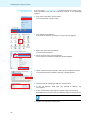
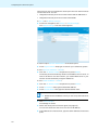
Microsoft Windows XP
operating system
If you are using Microsoft Windows XP, proceed as follows in order to set a
static IP address (see also the instruction manual of the operating
system):
왘 Click “Start” and select “Control Panel”.
The “Control Panel” window opens.
왘 Click “Network Connections“
A list of all the network connections on the computer appears.
왘 Right-click “Local Area Connection”.
A shortcut menu appears.
왘 On the shortcut menu, click “Properties”.
The “Local Area Connection Properties” window appears.
왘 Select “Internet Protocol (TCP/IP)” and click the “Properties” button.
The “Internet Protocol (TCP/IP) Properties” window appears.
왘 Click the “Use the following IP address” option button.
왘 In the “IP address” field, type your desired IP address, e.g.
192.168.0.12.
왘 In the “Subnet mask” field, type the subnet mask 255.255.255.0.
Both addresses have to be within the address range of the access point.
Do not use the IP address of the access point: 192.168.0.10.
왘 Confirm your entries by clicking “OK”.
46
Configuring the conference system
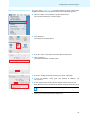
Apple MacOS X operating system
If you are using Apple MacOS X, proceed as follows in order to set a static
IP address (see also the instruction manual of the operating system):
왘 Click the “Apple” icon and select “System Preferences”.
The “System Preferences” window opens.
왘 Click “Network”.
The “Network” window opens.
왘 From the “Show” drop-down list, select “Built-in Ethernet”.
왘 Click “Configure...”.
The “Built-in Ethernet” window opens.
왘 From the “Configure IPv4” drop-down list, select “Manually”.
왘 In the “IP address” field, type your desired IP address, e.g.
192.168.0.12.
왘 In the “Subnet mask” field, type the subnet mask 255.255.255.0.
Both addresses have to be within the address range of the access point.
Do not use the IP address of the access point: 192.168.0.10.
왘 Confirm your entries by clicking “Apply now”.
47
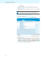
Configuring the conference system
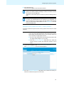
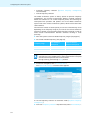
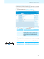
Accessing the access point (overview screen)
Make sure the network communication between access point
and computer is not blocked by a proxy server and/or a firewall.
왘 Switch the access point on (see page 29).
왘 Start a web browser (e.g. Internet Explorer or Firefox).
왘 In the address box of the browser, type the IP address of the access
point: the factory default IP address 192.168.0.10 or your adapted IP
address.
왘 Press the Enter key or click the “Refresh” button of your web browser.
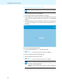
The web server appears in the browser window and prompts for a
password.
If you have not assigned a password:
왘 Type the default password “123” into the entry field.
왘 Click “OK”.
The “Summary” overview screen of the web server appears.
If you have assigned a password (see page 52):
왘 Type the password into the entry field.
왘 Click “OK”.
The “Summary” overview screen of the web server appears.
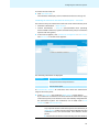
If you have forgotten the password, you can reset the access
point to the factory default settings in order to be able to access
the web server (see page 44).
Attention: If the access point is reset, any custom settings will
be lost!
48
Configuring the conference system
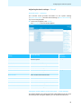
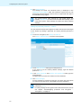
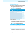
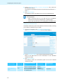
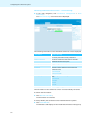
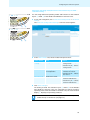
Adjusting the basic settings – “Setup“
Overview screen – “Summary“
The overview screen provides information on the system settings
(“System Information”) and the device settings (“Device Information”),
e.g. for servicing purposes.
왘 In the main navigation, click “Setup”.
The “Summary” overview screen appears.
Function/Meaning
Additional
information
“System Name“
User selectable name for the network address of the
conference system
see page 49
“IP Address“
IP address of the access point
“Subnet Mask“
Subnet address of the address point
“Address Mode“
Address mode of the network address
“Base MAC Address“
MAC address of the access point
“Serial Number“
Serial number of the access point
“Model Name“
Model name of the access point
“Hardware Version“
Version number of the hardware
“Boot Version“
Version number of the boot firmware
“Firmware Version“
Version number of the firmware
“FPGA Version“
Version number of the conference units’ firmware
“RF Hardware 1 Version“
Version number of the transmission hardware
“RF Hardware 2 Version“
Version number of the reception hardware
“RF Firmware 1 Version“
Version number of the transmission firmware
“RF Firmware 2 Version“
Version number of the reception firmware
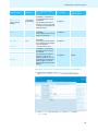
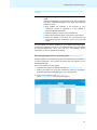
Setting
see page 67
Setting the network address of the access point – “TCP/IP Settings“
The fixed IP address 192.168.0.10 and the subnet address 255.255.255.0
are factory preset. Using this address, you can access the web server.
49
Configuring the conference system
There are two ways to integrate the access point into the network and to
use the web server. You can
•
integrate the access point into a network with static IP addresses or
•
integrate the access point into a network with DHCP.
To call up the IP address settings:
왘 In the main navigation, click “Setup” > “TCP/IP Settings”.
The “TCP/IP Settings” overview screen appears.
To set an unique network identification of the access point:
왘 In the “System Name” field, type a name for your conference system.
To use a dynamic IP address – “DHCP“:
왘 From the “IP Address Mode” drop-down list, select “DHCP”.
The access point automatically obtains its IP address from a server. In
order to be able to use this function, you need a DHCP server in your
network that automatically assigns IP addresses.
To use a static IP address – “Static“:
왘 From the “IP Address Mode” drop-down list, select “Static”.
왘 In the “IP Address” field, type the desired IP address.
왘 In the “Subnet Mask” field, type the desired subnet mask.
Make sure that this IP address is not used in your network.
왘 Note down the IP address so that you can call up the web server
again.
왘 Click “Save settings”.
The settings are saved.
왘 Switch the access point off and on again (see page 29).
You can now access the web server via the new IP address.
왘 In the address box of the browser, type the new IP address of the access
point.
50
Configuring the conference system
왘 Press the Enter key.
The web server appears in the browser window.
If you have forgotten the new IP address, you can reset the access
point to the factory default settings in order to be able to access
the web server (see page 44).
Attention: If the access point is reset, any custom settings will be
lost!
If you want to integrate the access point into a managed network
in which only selected devices are allowed to be integrated, you
have to assign your router or switch the MAC address of the access
point. You can find this MAC address on the “Summary” overview
screen (see page 49).
Setting the country-specific limit values – “Country selection“
To set the conference system to the country-specific limit values for radio
systems:
CAUTION! Risk of violation of legal requirements!
If you are using radio frequencies and transmission powers
that cannot be used license-free in your country, there is a
risk of violation of legal requirements.
왘 Use only radio frequencies and transmission powers that
are approved and legal in your country.
왘 From the “Country selection” drop-down list, select the
correct country is which the conference system is to be
used.
왘 In the main navigation, click “Setup” > “Country selection”.
The “Country selection” overview screen appears.
왘 From the “Country selection” drop-down list, select the country in
which the conference system is to be used.
51
Configuring the conference system
왘 Click “Save settings”.
The settings are saved. The selected country is displayed in the
“Selected Country Region” field. The conference system will only use
frequencies and transmission powers that are approved and legal in
the selected country/region.
The country-specific radio settings for the United States and
Canada, “US/Canada”, are the most restricted radio settings in the
conference system. These settings are used as the factory default
settings.
Setting the password protection – “Admin“
You can protect the access point against unauthorized access and changes
to the system by setting a password. The factory default password is
“123”.
왘 In the main navigation, click “Setup” > “Admin”.
The “Admin: authentication” overview screen appears.
왘 In the “Old password” field, type the old password.
If you want to use the factory default settings, type the default
password “123”.
왘 In the “New password” and “Confirm new password” fields, type the
new password.
The password can consist of a maximum of 50 characters.
왘 Click “Save settings”.
The new password is saved. The next time you switch the access point
on, access to the web server is protected by the new password.
If you reset the access point to the factory default settings, the
password is “123”.
For safety settings for encryption of the radio transmission, refer to
the chapter “Eavesdropping protection and encryption –
“Encryption”” on page 67.
52
Configuring the conference system
Adjusting the RF settings – “RF configuration“
Setting the RF signal strength – “General“
The RF signal strength of the conference system can be set in two different
ways:
•
automatic setting of the RF signal strength (recommended)
•
manual setting of the RF signal strength
왘 In the main navigation, click “RF Configuration”.
The “General RF settings” overview screen appears.
To set the RF signal strength to automatic mode:
왘 In the “Room size” box, select the “(Auto)” option button.
왘 Click “Save settings”.
The setting is saved. The RF signal strength is automatically adapted to
the operating conditions/room size.
To manually set the RF signal strength:
왘 In the “Room size” box, select the appropriate option button:
Option button
RF signal strength
Area of application
“Big“
maximum RF signal
strength
large rooms of
approx. 3000 m²
“Medium“
medium RF signal
strength
medium sized rooms of
approx. 2000 m²
“Small“
low RF signal strength
small rooms of
approx. 1000 m²
왘 Click “Save settings”.
The setting is saved. The RF signal strength is set to the selected power.
Setting the frequencies – “General“
The frequency selection of the conference system can be set in two
different ways:
53
Configuring the conference system
•
automatic frequency selection (dynamic frequency management;
recommended)
•
manual frequency selection
The WiCOS conference system is factory preset to dynamic frequency
management. This function automatically detects occupied frequency
bands and switches to an unused frequency band, thus allowing for
interruption-free operation and parallel use of the WiCOS conference
system with other wireless conference systems, WLAN routers and other
radio networks.
The maximum number of access points you can use simultaneously varies
depending on the frequency range. If you want to use several conference
systems in parallel, we recommend careful frequency planning in order to
avoid mutual intermodulation between channels working in close
proximity.
왘 Have the system scan the available frequency ranges (see page 56).
왘 Set a fixed available frequency (see page 53).
Frequency range
Max. number of
access points
Minimum distance
between access points
2.4 GHz
3
1.5 m
5.7-5.8 GHz
8
1.5 m
5.1-5.7 GHz
14
1.5 m
The scan of the available frequency ranges can take up to 60
seconds. This time is needed if the 2.4 GHz frequencies are occupied
and the 5 GHz frequencies have to be scanned.
During scanning, conferencing is not possible.
왘 In the main navigation, click “RF Configuration”.
The “General RF settings” overview screen appears.
To set the frequency selection to automatic mode (dynamic frequency
management):
왘 From the “Frequency Selection” drop-down list, select “Automatically”.
54
Configuring the conference system
왘 Click “Save settings”.
The setting is saved. The conference system automatically selects the
frequencies and switches to alternate frequencies if intermodulation
occurs.
To manually set a frequency range:
CAUTION! Danger of intermodulation!
If the automatic frequency management is deactivated, the
radio signals of the conference system and the radio signals
of other devices can be subject to intermodulation.
왘 Make sure that the manually set frequency ranges are not
used by other devices and are not subject to
intermodulate (see “Monitoring the frequency ranges –
“Quality“” on page 56).
왘 Use the dynamic frequency management.
To select an unused frequency range, use the frequency range monitoring
function which displays occupied and unused frequency ranges (see
page 56).
왘 From the “Frequency Selection” drop-down list, select an unused
frequency:
Color identification
Frequencies are ...
Function/Restriction
black
unused
You can use these
frequencies.
blue
currently unused
These frequencies can be
used by other devices (e.g.
radar equipment)
You can use these
frequencies. If
intermodulation occurs,
the system switches to
alternate frequencies.
light blue
occassionally used by
other devices (e.g. radar
equipment)
You can currently use
these frequencies.
red
currently used by other
devices (e.g. WLAN
equipment)
You should not use these
frequencies.
dark red
occassionally used by
other devices (e.g. radar
equipment)
You cannot use these
frequencies.
The selected frequency is shown under the drop-down list.
왘 Click “Save settings”.
The setting is saved. The conference system uses the selected
frequency.
55
Configuring the conference system
Monitoring the frequency ranges – “Quality“
The frequency range monitoring function displays occupied and unused
frequency bands.
왘 In the main navigation, click “RF Configuration”.
The “General RF settings” overview screen appears.
왘 Select the overview screen of the desired frequency range:
– “Quality 2.4 GHz ISM“
– “Quality 5.15-5.35 GHz“
– “Quality 5.47-5.725 GHz“
– “Quality 5.8 GHz ISM“
A bar chart of the selected frequency range is displayed. The colored
bars indicate the currently occupied and/or unused frequencies. The
red deflections indicate the amount of radio traffic.
56
Configuring the conference system
Color of bar
Radio traffic
green
No radio traffic on the corresponding frequency:
Your conference system should use this frequency.
red
Heavy radio traffic on the corresponding frequency:
Your conference system should not use this frequency.
If you have manually set your conference system to a frequency
range, it might be that the frequency range monitoring displays the
radio traffic of the set frequency range that is used by the
conference system itself.
This does not impair the operation of the conference system.
Adjusting the conference settings –
“Conference Management“
If you have integrated the WiCOS conference system into the wired
SDC 8200 conference and interpretation system, the conference
settings can be configured via the central unit of the wired system
(see page 73 and the instruction manual of the SDC 8200
conference and interpretation system).
Setting the maximum number of simultaneously active microphones
(speaker limit)
The speaker limit determines the maximum number of speakers who can
take the floor simultaneously. In the conference modes “FIFO” and “Group
1-4”, the speaker limit is preset to a fixed value.
If you set a high number of interpretation channels, the speaker
limit will be reduced.
왘 Reduce the number of interpretations channels in order to be
able to set the speaker limit to a maximum of 8 (see “Setting
the number of interpretation channels” on page 60).
왘 In the main navigation, click “Conference management”.
The “General Conference Settings” overview screen appears.
57
Configuring the conference system
왘 In the “Maximum number of active microphones” box, select the
desired option button.
The number of simultaneously active microphones can be between “1”
and “8”.
왘 Click “Save settings”.
The setting is saved. The speaker limit is set to the selected value.
Regardless of the conference mode and speaker limit set, the
following applies:
•
With a chairman unity you can take the floor immediately
without first having to be assigned the “speaking right”.
•
Active chairman units are not counted against the speaker limit.
Setting the conference mode
The WiCOS conference system offers different conference modes, allowing
you to tailor a conference to your needs.
왘 In the main navigation, click “Conference management”.
The “General Conference Settings” overview screen appears.
왘 In the “Microphone Mode” box, select the desired option button.
Refer to the table below for more information on the individual
conference modes.
왘 Click “Save settings”.
The setting is saved. The conference system is set to the selected
conference mode.
Conference mode
Speaker limit
By pressing the microphone
key A ...
Chairman unit
1 to 8
... you make a request to speak
and join the request-to-speak
list. You can only take the floor
after you have been assigned
the “speaking right”.
required –
assigns the
“speaking right”
“With request“
“With request no
clear“
58
Cancellation of a
request to speak
possible
not possible
Configuring the conference system
By pressing the microphone
key A ...
Speaker limit
“Direct access“
(factory default
setting)
... you can take the floor
immediately – provided that
the speaker limit has not yet
1 to 8 (factory
been reached.
default setting:
not required
If the speaker limit has been
4)
reached, you have to wait until
one of the current speakers has
finished speaking.
–
1
... you can take the floor
immediately.
not required
The microphone of the previous
speaker is switched off.
–
“Override“
1 to 8
... you can take the floor
immediately.
The microphone of the speaker not required
who is speaking for the longest
time is switched off.
–
“Group 1“
1
“Group 2“
2
“Group 3“
3
.... you can take the floor
immediately – provided that
the speaker limit has not yet
been reached.
If the speaker limit has been
reached, you will join the
request-to-speak list. You will
automatically be assigned the
“speaking right” as soon as
another speaker has finsished
speaking.
possible
“FIFO“
“Group 4“
4
Chairman unit
Cancellation of a
request to speak
Conference mode
not required
Setting the volume of the conference units’ built-in loudspeakers
왘 In the main navigation, click “Conference management”.
The “General Conference Settings” overview screen appears.
왘 in the “Volume” box, click the “Up” or the “Down” button.
– “0”
= off
59
Configuring the conference system
– “1”
= low
– “12” = very high
The selected volume level is displayed between the two buttons.
왘 Click “Save settings”.
The setting is saved. The loudspeaker volume is set to the selected
level.
The volume of the conference units’ loudspeakers can also be set
via the WiCOS CV or WiCOS C chairman unit (see page 41).
Setting the number of interpretation channels
왘 In the main navigation, click “Conference management”.
The “General Conference Settings” overview screen appears.
왘 In the “Number of interpretation channels” box, click the desired option
button.
You can offer “0”, “2”, “4”, “8”, “12” or “16” interpretation channels.
왘 Click “Save settings”.
The setting is saved. The maximum number of interpretation channels
is set (see also “Using the interpretation system” on page 79). If
necessary, the maximum number of simultaneously active
microphones (speaker limit) will be reduced (see page 57). Values that
can no longer be selected will be displayed in red in the “Maximum
number of active microphones” box.
60
Configuring the conference system
Setting the operating mode of the access point
The access point is suitable for stand-alone operation or can be integrated
into a wired SDC 8200 conference and interpretation system (slave mode
operation).
왘 In the main navigation, click “Conference management”.
The “General Conference Settings” overview screen appears.
왘 In the “Select the Operating Mode” box, select the “Stand Alone”,
“SDC 8200” or the “TCS 5500” option button.
Setting
Operating mode of the access point
“Stand Alone“
Stand-alone operation
“SDC 8200“
Integrated operation (slave mode operation)
The WiCOS conference system is integrated into a
wired conference and interpretation system and
operates in slave mode (see page 73 and the
instruction manual of the SDC 8200 or TCS 5500
system).
“TCS 5500“
왘 Click “Save settings”.
The setting is saved. The access point is set to the desired operating
mode.
The status indicator ^ provides information on the operating mode:
^
Blue LED 1 ...
Operating mode of the access point
flashes slowly
Integrated operation (slave mode)
lights up
Stand-alone operation
61
Configuring the conference system
Monitoring initialized conference units – “Unit monitoring“
왘 In the main navigation, click “Conference management” > “Unit
monitoring”.
The “Unit monitoring” overview screen is displayed.
The following information on the initialized conference units is displayed:
Information
Function/Meaning
“Units initialized“
Number of conference units that are initialized with
the access point and currently switched on
“Units in init list“
Number of conference units that are manually
initialized with the access point
“Microphone Number“
4-digit microphone number
“Serial Number“
Serial number of the conference unit
“Status“
Connection status between access point and
conference units:
• “Connected“
• “Disconnected“
“Link Quality“
Link quality between access point and conference
units:
• “Excellent“
• “Good“
• “Fair“
• “Low“
“Battery Status“
Remaining operating time in hours
The information on the conference units is not automatically refreshed.
To refresh the information:
왘 Click “Refresh Unit Table”,
The information is refreshed.
To clearly identify the conference units initialized with the system:
왘 Click “Test LEDs ON”.
The indicators and displays of the initialized conference units light up.
62
Configuring the conference system
To switch the test mode off:
왘 Click “Test LEDs OFF”.
The indicators and displays of the initialized conference units go off.
Initializing the conference units with the access point – “Init Units“
There are two ways to initialize the conference units with the access point:
•
automatic initialization – “Open access“
•
manual initialization – “Manual” (recommended when operating
several WiCOS conference systems simultaneously and/or conference
systems with encryption)
왘 In the main navigation, click “Conference management” > “Init units”.
The “Init units” overview screen appears.
The following information is displayed:
Information
Function/Meaning
“Units initialized“
Number of conference units that are initialized with the
access point and currently switched on
“Units in Init List“
Number of conference units that are manually initialized
with the access point
To automatically initialize all conference units within the transmission
range of the access point:
왘 In the “Init Control” box, select the “Open Access” option button.
If you switch on a conference unit that is within the transmission range
of the access point, the conference unit is automatically integrated into
the conferences system. This conference unit is listed under “Units
Initialized” and “Unit monitoring”.
CAUTION! Intermodulations in conferences!
If you operate several conference systems simultaneously in
“Open Access” mode, this will cause intermodulations as the
conference units will communicate with different access
points.
왘 Initialize the conference units manually (see next section).
63
Configuring the conference system
To manually initialize certain conference units with the access point:
왘 Switch on all conference units that you want to use in your conference
system (see page 31).
왘 In the “Init Control” box, select the “Manual” option button.
왘 Click “Clear Init List”.
The existing “Units in Init List” list will be deleted (where applies).
왘 Click “Start init”.
The initialization process starts. All conference units that are
operational show a microphone LED 0 flashing green and red and a
signal light ring 2 flashing red.
C CV D DV
V
2
:
:
C CV D DV
2
왘 Press the microphone key A of the conference unit that you want to
initialize.
The microphone LED 0 and the signal light ring 2 go off. The
conference unit is initialized and listed in the “Units in Init List”. The
conference units are assigned microphone numbers in the order of
initialization. These microphone numbers allow you to clearly identify
the conference units.
왘 Repeat these steps for all conference units that you want to initialize.
:
:
A
Make sure that no conference units are initialized unintentionally.
왘 Use the “Unit Monitoring” function to check that only “wanted”
conference units are initialized (see page 62).
왘 Click “Save and Stop Init”.
The initialization process is stopped. The initialized conference units
are saved in the “Units in Init List”. The microphone LED 0 and the
signal light ring 2 go off.
When the conference system is switched on the next time, only the
conference units listed in the “Units in Init List” will be used for
conferencing.
In order to increase the safety of your conference system, you can
individually adjust the encryption of the radio communication (see
“Eavesdropping protection and encryption – “Encryption”” on
page 67).
64
Configuring the conference system
Setting the operating mode/functions of the selection keys A and B –
“Chairman Config”
You can assign different operating modes and functions to the selection
keys A 8 and B 9 of the WiCOS C and WiCOS CV chairman units.
C CV D DV
왘 In the main navigation, click “Conference Management” > “Chairman
Config”.
The “Chairman Configuration Settings” overview screen appears.
9
8
9
8
C CV D DV
왘 In the “Menu Mode” box, select the desired option button:
Option button
Mode
Function
“Start/Stop
Voting“
Voting mode
• Selection key A 8 stops a
voting session
• Selection key B 9 starts a
voting session
“Volume Control“ Volume adjustment mode • Selection key A 8
for loudspeakers
increases the volume
• Selection key B 9 reduces
the volume
“Function key“
Media control mode
• Selection key A 8 controls
external media devices
• Selection key B 9 controls
external media devices
왘 Click “Save settings”.
The setting is saved. The selection keys A 8 and B 9 of the WiCOS C
and WiCOS CV chairman units are assigned the desired function/
operating mode. With the WiCOS CV chairman unit, the multi-function
display 7 displays the operating mode set.
With the WiCOS CV chairman unit, you can also set the operating
modes directly on the device (see page 15).
65
Configuring the conference system
Additional functions – “Service“
Logging function
The access point logs various operating procedures. This function is
primarily used as a diagnostic aid for troubleshooting.
왘 In the main navigation, click “Service”.
The “Logging” overview screen appears.
To start the logging:
왘 Click “Start”.
The logging starts.
To stop the logging:
왘 Click “Stop”.
The logging stops.
To save the log entries:
왘 Highlight the log entries.
왘 Cut and paste the log entries into your word processing program.
To delete the log entries:
왘 Click “Clear”.
The log entries are deleted.
The logging function does not log the voting results.
66
Configuring the conference system
Updating the firmware of the access point and the conference units –
“Update“
CAUTION! Danger of damage to the access point and the conference
units!
Improper modification of the firmware (e.g. due to updates)
can cause irreparable damage to the access point and the
conference units.
왘 Only update the firmware if the function of your
conference system is impaired or if the update is
recommended by Sennheiser.
왘 Make sure that you use the correct update file.
왘 Follow the instructions given in the service information.
왘 While the update is in process, do not disconnect the
access point and the conference units form the power
supply.
For information on firmware updates for your WiCOS conference system,
contact your Sennheiser partner or visit the download area of our website
at www.sennheiser.com. There you will also find detailed service
information on how to update the firmware.
Eavesdropping protection and encryption – “Encryption”
All radio signals in the conference system are automatically encrypted via
a 128-bit algorithm. This function prevents that the signals can be
eavesdropped upon.
There a two ways to use encryption:
•
automatic encryption via default encryption (“Use default key”)
•
custom encryption for using the conference system in encryptionprotected operation and adapting it to your requirements
왘 In the main navigation, click “Encryption”.
The “Key assignment” overview screen appears.
67
Configuring the conference system
Using default encryption
왘 In the “default key” box, select the “Use default key” option button.
The setting is saved. The system encrypts all radio signals with the
default encryption key. All components of the WiCOS series can
communicate with each other using this encryption key.
If you select the default encryption “default key”, you can use all
WiCOS conference units without restrictions.
Using custom encryption
To use custom encryption and protect the system against unauthorized
access by further WiCOS conference units:
왘 Initialize all required conference units with the access point (see
page 63).
왘 If necessary, use the “Unit monitoring” function to check that only
“wanted” conference units are initialized (see page 62).
왘 In the “custom key” box, select one of the “Use custom key ...” option
buttons.
왘 Generate an encryption key by clicking “Calc.” (“Calculate”).
An arbitrary key is generated in the corresponding “Use custom key ...”
field. The key is saved in this field.
Or:
왘 Enter a custom key into one of the “Use custom key ...” fields.
The key must consist of 32 hexadecimal characters. You can use
– numbers from 0 to 9 and
– letters from A to F.
If you enter a key shorter than 32 characters, the missing characters
will be filled in with zeros. If you enter a key longer than 32 characters,
the exceeding characters will be dropped. The entered key is saved in
the corresponding “Use custom key ...” field.
To assign the custom encryption key to the currently initialized conference
units:
왘 Click “Upl. key” (“Upload key”).
A safety query appears.
왘 Click “OK” to assign the custom encryption key to the initialized
conference units.
The custom encryption key is transferred to all currently initialized
conference units. During the transfer, the microphone LED 0 and the
signal light ring 2 of the conference units flash red. You can use the
current conference configuration again the next time you switch the
conference system on.
Only switched-on conference units that have been assigned the
custom encryption key can be used in the encryption-protected
conference configuration.
To add a conference unit to a conference configuration that uses custom
encryption:
왘 Initialize all required conference units with the access point (see
page 63).
68
Configuring the conference system
왘 Assign these conference units the desired custom key as described on
page 68.
To no longer use a custom key:
왘 Initialize all required conference units with the access point (see
page 63).
왘 In the “default key” box, select the “Use default key” option button.
The setting is saved. The system encrypts all radio signals with the
default encryption key. The access point can now use all WiCOS
conference units again.
Automatic encryption and individual encryption both have an
identical encryption algorithm. The custom key allows you to adapt
the conference system to your requirements and protect it against
unauthorized access.
To delete a custom key:
왘 In the “custom key” box, select the custom key to be deleted by clicking
the corresponding “Use custom key ...” option button.
왘 Press the Delete key to delete the selected custom key.
Or:
왘 Overwrite the selected custom key with a new custom key.
Using previously saved custom encryption keys
The conference units and the access point can manage up to 15 custom
encryption keys. This allows you to specify which conference units are
admitted to the conference.
왘 In the “custom key” box, select one of custom keys by clicking the
corresponding “Use custom key ...” option button.
All conference units that have been assigned this custom key can be
linked to the access point and can be used for the conference
configuration.
Note down which custom key “Custom key ...” is used by which
conference configuration. Also note down the custom keys. The
software does not save the custom keys as text, i.e. they cannot be
restored.
69
Transporting the conference system
Transporting the conference system
One of the advantages of the WiCOS wireless conference system is that it
is easy to set up and dismantle again. This makes the conference system
mobile and ensures flexibility of use.
Preparing the access point for transport
왘 Switch the access point off (see page 29).
왘 Unplug the DC power supply from the wall socket.
왘 If necessary, disconnect any cables connected to the access point.
l
j
k
h
왘 Remove the 3 antennas a by unscrewing the coupling rings c and
carefully pulling the antennas out of the antenna sockets e.
a
c
a
e
왘 Pack the individual components of the access point up safely. Make
sure that the components are protected against shocks and humidity.
70
Transporting the conference system
Preparing the conference units for transport
왘 If necessary, unplug the charging power supply from the wall socket
왘 Unplug the connector from the socket for charging power supply.
C CV D DV
X
왘 If necessary, disconnect any headphones connected to the conference
unit.
왘 Unscrew the coupling ring 3 of the gooseneck microphone.
3
4
왘 Carefully pull the gooseneck microphone out of the microphone
socket 4.
CAUTION! Risk of short-circuiting and fire!
If the Lithium-Ion battery pack is transported or stored
incorrectly, it can short-circuit and catch fire.
왘 Make sure that the battery pack cannot come into contact
with small electrically conducting parts or liquids.
왘 Wrap the battery pack individually in material which does
not conduct electricity.
We recommend removing the battery pack from the conference
unit for transport or storage (see page 27).
왘 Pack the individual components of the conference unit up safely. Make
sure that the components are protected against shocks and humidity.
71
Transporting the conference system
Using the transport case
For transporting the conference system, we recommend WiCOS CASE, an
optionally available transport case on wheels. This case has padded
compartments for an access point, 12 conference units and the
microphones. It also allows you to pack and transport the power supply
units and other accessories safely.
To pack the transport case:
왘 Prepare the access point and the conference units for transport (see
page 70).
왘 Insert the access point into the access point holder |.
s
|
{
z
왘 Insert the conference units with the battery packs into the conference
unit holder z.
왘 Insert the gooseneck microphones into the microphone holder s.
왘 Pack the accessories such as antennas, cables or power supply units
into the compartment {.
The conference system is securely packed and protected against
shocks, dust and humidity.
To use the telescopic handle:
왘 Slide the catch v to the right and pull out the telescopic handle u.
u
왘 Transport the case carefully.
v
72
Integrating WiCOS into a wired conference system
Integrating WiCOS into a wired
conference system
You can integrate the WiCOS wireless conference system into the wired
SDC 8200 conference and interpretation system.
The advantages of integrated operation (slave mode operation) are as
follows:
•
the wired SDC 8200 conference and interpretation system is easy to
expand using the conference units of the WiCOS series, which are
wireless and can be placed as you wish
•
the WiCOS conference units are fully compatible with the SDC 8200 CUM and SDC 8200 CU central units
•
all conference modes and voting functions can be used (“yes”, “no”
and “abstain”)
•
language distribution with up to 16 interpretation channels
In addition, you can integrate the WiCOS wireless conference system into
the wired Televic TCS 5500 conference and interpretation system. For
more information, refer to the instruction manual of the TCS 5500 system.
Set up for integrated operation
(slave mode operation)
SDC 8200 conference units
SDC 8200 conference units
WiCOS AP
WiCOS AP
SDC 8200 CU/CU-M
WiCOS CV
WiCOS C
WiCOS DV
WiCOS D
Computer
Connecting the access point to the SDC 8200 CU central unit
To integrate the WiCOS conference system into the wired SDC 8200
conference and interpretation system, proceed as you would to connect a
conference unit to the SDC 8200 CU-M or SDC 8200 CU central unit. All
wireless conference units are recognized by the SDC 8200 CU-M or SDC
8200 CU central unit, just like wired ones are.
73
Integrating WiCOS into a wired conference system
For information on the configuration of your conference system, refer to
the instruction manual of the SDC 8200 conference and interpretation
system.
You require system cables for slave mode operation of the WiCOS system.
The system cables are available in lengths of 2 m, 3 m, 5 m, 10 m, 20 m
and 50 m (see “Accessories and spare parts” on page 83).
The system cables are used:
•
to connect the access point to the SDC 8200 CU-M or SDC 8200 CU
central unit or
•
to interconnect several access points.
Several access points connected in series allow you to optimize the radio
coverage, for example in order to hold a conference in several rooms at the
same time.
The number of (wired and wireless) conference units is subject to the
following restrictions in integrated operation (slave mode operation):
Number of conference units
SDC 8200 CU-M
SDC 8200 CU
< 50
yes
yes
> 50
–
yes
Connecting the access point to the central unit
The length of the system cable between central unit and access
point must not exceed 80 m.
왘 Connect the black RJ 45 plug of the system cable to one of the six RJ 45
sockets (“PORT 1- 6”) of the SDC 8200 CU-M or SDC 8200 CU central
unit.
j
SDC 8200 CU
PORT 1-6
Accesspoint
WiCOS AP
왘 Connect the grey RJ 45 plug of the system cable to the IN socket
(RJ 45) j of the access point.
The access point is connected to the central unit.
In slave mode operation, the access point is powered via the central
unit and the system cable. However, you can also connect the DC
power supply. In this case, the power supply is automatically
switched off via the system cable.
왘 Establish the network connection to your access point in order to be
able to use the web server (see page 48).
왘 On the web server, set the operating mode of the access point to “Slave
Mode” (see page 61).
The conference system can now only be configured via the
SDC 8200 CU-M or SDC 8200 CU central unit (see page 77).
74
Integrating WiCOS into a wired conference system
Interconnecting several access points
Several interconnected access points are used:
•
to operate small wireless conference systems in stand-alone operation
in several rooms in parallel and to interconnect these systems for slave
mode operation if required and
•
to increase the radio coverage.
The length of the system cable between two access points must
not exceed 80 m.
왘 Use a system cable to connect the OUT socket (RJ 45) k of one access
point to the IN socket (RJ 45) j of the next access point.
max. 80 m
SDC 8200 CU
max. 80 m
WiCOS AP
WiCOS AP
왘 To connect additional access points, proceed as described above.
You can connect a maximum of 15 interconnected access point to
one of the six RJ 45 sockets (“PORT 1- 6”) of the central unit.
Initializing the conference units with the SDC 8200 CU
central unit
In slave mode operation, you initialize all conference units (wired and
wireless) with the SDC 8200 CU-M or SDC 8200 CU central unit of the SDC
8200 conference and interpretation system.
Automatically initializing all conference units with the central unit
The automatic initialization allows you to initialize all conference units at
once. In this case, the conference units are assigned microphone numbers
automatically, in an arbitrary order.
왘 Switch on all wireless conference units that you want to use in your
conference system (see page 31)
왘 Initialize the wireless conference units with the access point integrated
into your SDC 8200 conference and interpretation system (see
page 63).
SDC 8200 CU
å
ç
† ¢
왘 Press the ENTER key † on the SDC 8200 CU-M or SDC 8200 CU central
unit to get into the central unit’s operating menu.
The first main menu “Conference” appears on the display å.
75
Integrating WiCOS into a wired conference system
왘 From the central unit’s operating menu, choose with the jog wheel ç
“Conference”, “Initialise Units” and “Automatic Init” one after
the other.
The text “Please wait” is shown on the display.
Initialise Units
2
Automatic Init
Automatic Init
Please wait
왘 When the text “Press ENTER to Save Initialisation” is shown on
the display, press the ENTER key †.
The configuration is saved. All connected wired conference units and
the switched-on wireless conference units that were initialized with
the access point are initialized automatically. Any previous
configuration is deleted.
Automatic Init
Press ENTER to
Save Initialisation
Manually initializing all conference consoles with the central unit
If it is important that the conference units are assigned microphone
numbers in a certain order or if you only want to use certain wireless
conference units, we recommend choosing the manual initialization.
왘 Switch on all wireless conference units that you want to use in your
conference system (see page 31)
왘 Initialize the wireless conference units with the access point integrated
into your SDC 8200 conference and interpretation system (see
page 63).
왘 From the central unit’s operating menu, choose with the jog wheel å
“Conference”, “Initialise Units” and “Manual Init” one after the
other.
The red signal light rings ¶ and „Microphone active“ LED • on all wired
conference consoles flash. With all wireless conference units, the
microphone LED 0 flashes red and green and the signal light ring 2
flashes red.
Initialise Units
1
Manual Init
SDC
C CV D DV
V
¶
2
:
£
§
•
:
Only the signal light rings of the conference units are flashing while
the signal light rings of the interpreter units remain dark.
Initialization of the interpreter units is via the “Interpretation”
menu (see the instruction manual of the SDC 8200 conference and
interpretation system).
76
Integrating WiCOS into a wired conference system
Full Init
Press ENTER to Save
왘 Choose with the jog wheel ç “Full
Init”.
왘 One after the other, press the microphone key A or § of all conference
units in the order in which they are to be initialized.
As soon as the initialization of a wired conference unit is accepted by
the central unit, the signal light ring ¶ and the „Microphone active“
LED • of this conference unit go off.
With the wireless conference units, the microphone LED 0 and the
signal light ring 2 go off.
왘 Press the ENTER key † on the central unit to save this configuration.
Configuring the complete conference system - slave mode
operation)
If the access point is in slave mode operation, you configure the conference
system including the wireless conference units optionally via the :
•
SDC 8200 CU-M central unit
•
SDC 8200 CU central unit
•
SDC 8200 SYS-M PC control software
•
SDC 8200 SYS PC control software
(see the instruction manual of the SDC 8200 conference and interpretation
system).
WiCOS CV
WiCOS C
WiCOS DV
WiCOS D
WiCOS AP
SDC 8200 CU
WiCOS AP
SDC 8200 conference units
The web server of the access point offers you all setting and monitoring
options as before. However, only the following settings have an effect on
conference operation:
•
In slave mode operation, you have to set the “Maximum number of
active microphones” for the wired conference units via the SDC 8200
CU-M or SDC 8200 CU central unit and for the wireless conference units
via the web server (see page 57).
•
In slave mode operation, the “Number of Interpretation channels” also
affects the maximum number of active microphones of the wireless
conference units (see page 60).
•
As a result of the different speaker limits of the central unit and the
access point, it is not possible to use the “FIFO” conference mode in
slave mode operation.
All other configurations can be changed, but in slave mode operation the
changes do not affect conferencing.
77
Integrating WiCOS into a wired conference system
Using stand-alone operation in parallel with slave mode
operation
Once you have connected one or several access points to the SDC 8200
conference and interpretation system, you can continue to use an access
point for stand-alone operation. For example, you can hold several
conferences in parallel, in different rooms for instance. The SDC 8200
conference and interpretation system allows you to link all conferences to
form one integrated conference.
WiCOS CV
WiCOS C
WiCOS DV
WiCOS D
WiCOS AP
SDC 8200 CU
WiCOS AP
SDC 8200 conference units
To use stand-alone operation in parallel to slave mode operation:
왘 Set the operating mode of the access point to “Stand Alone” (see
page 61).
The WiCOS conference system functions completely independently of
the SDC 8200 conference and interpretation system.
Holding a conference in slave mode operation
Discussion mode
The conference mode is set via the SDC 8200 CU-M or SDC 8200 CU central
unit. (see the instruction manual of the SDC 8200 conference and
interpretation system).
The conference units of the WiCOS conference system behave as they
would in stand-alone operation. For detailed information on the use of the
conference units, refer to page 33 and page 36.
Carrying out voting sessions
In order to start a voting session, you require the WiCOS CV or SDC 8200 CV
chairman unit (see page 38 and the instruction manual of the SDC 8200
conference and interpretation system). You can also conveniently plan,
manage and hold voting sessions via the SDC 8200 SYS-M or SDC 8200 SYS
PC control software.
In order to be able to participate in voting sessions, you require a
conference unit with voting function (see table below). For detailed
information on how to participate in a voting session, refer to page 34 and
78
Integrating WiCOS into a wired conference system
to the instruction manual of the SDC 8200 conference and interpretation
system.
Only start voting sessions using the voting function with the
parliamentary voting options (“yes”, “no”, “abstain”) as the WiCOS CV and
WiCOS DV conference units support only this voting function. Otherwise,
the result of the voting session could be falsified.
Conference unit
Voting function
Voting options
Voting
administrator
function
WiCOS CV
yes
3
yes
WiCOS DV
yes
3
no
WiCOS C
no
–
–
WiCOS D
no
–
–
SDC 8200 C
yes
3
no
SDC 8200 D
yes
3
no
SDC 8200 CC
yes
3
no
SDC 8200 DC
yes
3
no
SDC 8200 CV
yes
5
yes
SDC 8200 DV
yes
5
no
SDC 8200 ID
no
–
–
In slave mode operation, the SDC 8200 SYS-M or SDC 8200 SYS PC control
software allows you to:
•
conduct a secret ballot (all LEDs next to the voting keys B, C and D
will light up after you have pressed a key)
•
log the voting result
•
graphically display the voting result
•
adjust additional voting options
For detailed information on the voting functions, refer to the instruction
manual of the SDC 8200 SYS-M and SDC 8200 SYS PC control software.
Using the interpretation system
In order to be able to offer interpretations using the WiCOS system, you
require the following components:
•
SDC 8200 conference and interpretation system with SDC 8200 CU-M
or SDC 8200 CU central unit
•
up to 16 SDC 8200 ID interpreter units
•
WiCOS CV chairman units
•
WiCOS DV delegate units
In addition, you can also use the following wired SDC conference units:
SDC 8200 DC, SDC 8200 CC, SDC 8200 DV and SDC 8200 CV.
79
Integrating WiCOS into a wired conference system
Slave mode operation with an
interpretation system
SDC 8200 conference units
SDC 8200 ID
interpreter units
WiCOS AP
WiCOS AP
SDC 8200 CU/CU-M
WiCOS CV
WiCOS DV
Computer
Configuring the interpretation system
For how to configure the interpretation system and how to use the
SDC 8200 ID interpreter units, refer to the instruction manual of the
SDC 8200 conference and interpretation system and to the instruction
manual of the SDC 8200 SYS-M and SDC 8200 SYS PC control software.
Depending on the settings of the SDC 8200 conference and interpretation
system, you have to adapt the following configuration of the access point
to your interpretation system:
왘 Set the maximum number of interpretation channels “Number of
Interpretation channels” (see page 60).
The WiCOS conference system can process up to 16 interpretation
channels. In slave mode operation, the number of interpretation
channels also affect the maximum number of simultaneously active
microphones of the wireless conference units (see page 60).
Listening to the interpretation channels
For how to listen to interpretations using the WiCOS CV and WiCOS DV
conference units, refer to page 35.
80
Cleaning the conference system
Cleaning the conference system
CAUTION! Liquids can damage the electronics of the devices!
Liquids entering the housing of the devices can cause a
short-circuit and damage the electronics.
왘 Keep all liquids away from the devices.
왘 Do not use any solvents or cleansing agents.
왘 Only use a slightly damp cloth to clean the devices from time to time.
81
If a problem occurs ...
If a problem occurs ...
Problem
Possible cause
Access point cannot be
The DC power supply is not suitable
switched on even though it
(e.g. you are using the WiCOS NT-BA
is connected to the DC
charging power supply).
power supply
Web server cannot be
called up
Conference unit does not
establish a transmission
link with the access point
Charge capacity drops
rapidly
Use the WiCOS NT-AP DC power supply for
powering the access point.
Make sure that the access point is correctly
The network connection is not correctly
connected to the network/the computer
established.
(see page 22).
The IP address of the access point has
been changed.
Load the factory default settings and call up the
web server using the address 192.168.0.10
(see page 44).
The transmission range is exceeded.
Reduce the distance between conference units and
access point. Place the access point as centrally and
as high as possible (see page 23).
The access point uses an encryption
key that has not been assigned to the
conference unit.
Set the encryption key of the access point to
“default key” (automatic encryption)
(see page 67).
Assign the conference unit the same custom
encryption key that is used by the access point
(see page 67).
The access point is just scanning the
frequency bands.
Wait until the frequency bands have been scanned
(this takes approx. 60 seconds).
The transmission range is exceeded.
Reduce the distance between conference units and
access point. Place the access point as centrally and
as high as possible (see page 23).
Poor radio communication
between access point and
conference units
Battery pack cannot be
recharged
Possible solution
Increase the transmission power or set the
transmission power to “Auto” (see page 53).
The antennas are wrongly aligned or
wrongly connected.
Only use the supplied antennas and make sure that
they are correctly connected to the access point.
Always align the antennas vertically and parallel to
each other (see page 23).
The charging power supply is not
suitable (e.g. you are using the
WiCOS NT-AP DC power supply ).
Use the WiCOS NT-BA charging power supply for
charging the battery pack.
The battery pack is defective.
Check the status of the charging electronics (see
page 26) and, if necessary, replace the defective
battery pack by a new one.
The battery pack is aged.
Replace the aged battery pack by a new one.
You are using WiCOS D or WiCOS DV
After switch-on, the
delegate units exclusively. The
delegate units only indicate conference mode chosen requires a
requests to speak
chairman unit for assigning the
“speaking right” (e.g. “With request”).
Use a chairman unit to assign the “speaking right”
or set a conference mode which does not require
the assignment of the “speaking right” (see
page 57).
Conference unit is
activated but the
microphone does not work
Make sure that the microphone is correctly
connected to the conference unit (see page 25).
The microphone is wrongly connected.
If a problem occurs that is not listed in the above table or if the problem cannot be solved with the proposed
solutions, please contact your local Sennheiser partner for assistance.
To find a Sennheiser partner in your country, search at www.sennheiser.com under “Service & Support”.
82
Accessories and spare parts
Accessories and spare parts
Cat. No.
Product name
System components
502068
WiCOS AP
Access point
502062
WiCOS D
Delegate unit
502061
WiCOS C
Chairman unit
502066
WiCOS DV
Delegate unit with voting function and channel
selection keys
502065
WiCOS CV
Chairman unit with voting function and channel
selection keys
Battery pack
502882
WiCOS BA
Lithium-Ion battery pack for WiCOS conference units
Microphone
502883
WiCOS MIC
Gooseneck microphone
Power supplies
502897
WiCOS NT AP
DC power supply for access point
502885
WiCOS NT BA
Charging power supply for WiCOS BA battery pack
Transport case
502071
WiCOS CASE
Transport case (with wheels) for one conference
system with up to 12 conference units and
accessories
System cables
009842
SDC CBL RJ-45-2
System cable with two shielded RJ 45 plugs, 2 m
009853
SDC CBL RJ-45-3
System cable with two shielded RJ 45 plugs, 3 m
009844
SDC CBL RJ-45-5
System cable with two shielded RJ 45 plugs, 5 m
009845
SDC CBL RJ-45-10
System cable with two shielded RJ 45 plugs, 10 m
009846
SDC CBL RJ-45-20
System cable with two shielded RJ 45 plugs, 20 m
009847
SDC CBL RJ-45-50
System cable with two shielded RJ 45 plugs, 50 m
Accessory
043207
Thread insert (3/8" to 5/8")
83
Specifications
Specifications
WiCOS AP access point
Frequency response
150 - 15,000 Hz
Frequency ranges
2,4 GHz; 5,1 - 5,8 GHz
Signal-to-noise ratio
> 70 dB(A)
Supply voltage
24 V DC
Power consumption
6W
Operating temperature
+5 °C to +45 °C
Dimensions
approx. 260 mm x 230 mm x 38 mm
Weight
approx. 1220 g
Color
RAL 7035
WiCOS D/WiCOS C/WiCOS DV/WiCOS CV conference units
Audio quality
16 bit / 32 kHz
Headphone socket
Output power at
headphone output
Power consumption
Operating time
Operating temperature
Dimensions
Weight (incl. battery pack)
Color
3.5 mm ( > 32 Ω < 1 kΩ)
16.5 mW / 32 Ω
approx. 3 W
> 20 hrs (WiCOS BA battery pack)
+5 °C to +45 °C
ca. 230 mm x 130 mm x 60 mm
ca. 830 g
RAL 9011
WiCOS BA Lithium-Ion battery pack
Nominal output voltage
7.2 V
Capacity
6600 mAh
Charging voltage
15 V ... 18 V
Charging current
2A
Charging time
approx. 4 hrs
Operating temperature
0 °C to + 45 °C
Dimensions
approx. 170 mm x 75 mm x 25 mm
Weight
approx. 380 g
Color
RAL 9011
WiCOS MIC gooseneck microphone
84
Pick-up pattern
cardioid
Frequency response
50 - 20,000 Hz
Sensitivity (1 kHz)
8 mV / Pa +/– 2.5 dB
Max. SPL (1 kHz)
133 dB
Temperature range
0 °C to + 45 °C
Specifications
Microphone gooseneck length
approx. 380 mm
Weight
approx. 70 g
Color
matt black
Certifications (WiCOS AP, WiCOS D, C, DV, CV, WiCOS BA)
In compliance with
Europe:
EMC
Radio
Safety
EN 301489-1/-17
EN 300328
EN 301893
EN 300440-1/-2
EN 60065
EN 62311 (SAR)
USA (WiCOS BA only): Meets the requirements of the UL 1642 safety standard.
The devices can be operated license-free in most countries of the European Union.
Approved by
Canada:
Industry Canada RSS 210
IC: 2099A-SDCW9000AP
IC: 2099A-SDCW9000DU
USA:
47 CFR Part 15
FCC ID: DMOSDCW9000AP
FCC ID: DMOSDCW9000DU
Power supplies
WiCOS NT-BA
WiCOS NT-AP
Input voltage
100 - 240 V /
50 - 60 Hz
100 - 240 V /
50 - 60 Hz
Input current (max.)
700 mA
400 mA
Output voltage
15 V
24 V
Output power
2A
0.625 A
Operating temperature
0 °C to + 40 °C at maximum load
Storage temperature
– 40 °C to + 70 °C
Certifications (WiCOS NT-BA and WiCOS NT-AP)
In compliance with
Europe:
USA:
Canada:
EMC
EN 55022, EN 55024
Safety
EN 60950
47CFR Part 15
ICES 0003
Certified by
Europe:
USA/Canada:
ENEC, VDE
cULus
85
Manufacturer Declarations
Manufacturer Declarations
Warranty
Sennheiser electronic GmbH & Co. KG gives a warranty of 24 months on this
product.
For the current warranty conditions, please visit our web site at
www.sennheiser.com or contact your Sennheiser partner.
CE Declaration of Conformity
0682
These devices are in compliance with the essential requirements and other
relevant provisions of Directives 2004/108/EC, 2006/95/EC and 1999/
05/EC.
The declaration is available at www.sennheiser.com.
Before putting the devices into operation, please observe the respective
country-specific regulations.
Batteries or rechargeable batteries
The supplied batteries or rechargeable batteries can be recycled. Please
dispose of them as special waste or return them to your specialist dealer.
In order to protect the environment, only dispose of exhausted batteries.
Statements regarding FCC and Industry Canada
This device complies with Part 15 of the FCC Rules and with RSS-210 of
Industry Canada. Operation is subject to the following two conditions: (1)
this device may not cause harmful interference, and (2) this device must
accept any interference received, including interference that may cause
undesired operation.
This equipment has been tested and found to comply with the limits for a
Class B digital device, pursuant to Part 15 of the FCC Rules. These limits are
designed to provide reasonable protection against harmful interference in
a residential installation. This equipment generates, uses and can radiate
radio frequency energy and, if not installed and used in accordance with
the instructions, may cause harmful interference to radio communications.
However, there is no guarantee that interference will not occur in a
particular installation. If this equipment does cause harmful interference
to radio or television reception, which can be determined by turning the
equipment off and on, the user is encouraged to try to correct the
interference by one or more of the following measures:
•
Reorient or relocate the receiving antenna.
•
Increase the separation between the equipment and receiver.
•
Connect the equipment into an outlet on a circuit different from that
•
to which the receiver is connected.
•
Consult the dealer or an experienced radio/TV technician for help.
This class B digital apparatus complies with the Canadian ICES-003
Changes or modifications made to this equipment not expressly approved
by Sennheiser electronic Corp. may void the FCC authorization to operate
this equipment.
86
Manufacturer Declarations
Before putting the device into operation, please observe the respective
country-specific regulations!
USA (WiCOS BA only): Meets the requirements of the UL 1642 safety
standard. The devices can be operated license-free in most countries of the
European Union. For more information, please contact your local
regulatory authority for radio and telecommunications or your Sennheiser
partner.
87
Index
Index
A
Access point 9, 18, 21, 22, 23
configuring the access point 48
connecting to the SDC 8200 CU
central unit 73
initializing the conference units
with the access point 63
preparing the access point for
transport 70
setting the country-specific limit
values 51
setting the network address 49
switching off 30
switching on 29
Country selection 51
D
Accessories 83
Direct access 59
Address range 45
Admin 52
Discussion
ending a discussion 37
B
Dynamic frequency
management 54
Battery pack
charging 26
checking the charge status 26
inserting 27
removing 27
C
Certifications 85
Chairman Config 65
Function key 65
Start/Stop Voting 65
Volume Control 65
Channel selection display 13, 16
Cleaning 81
Conference Management 57
Conference mode 58
setting the conference mode 58
Conference settings
configuring the conference
settings 57
Conference unit
changing the volume of the conference units’ loudspeakers 41
initialization with the SDC 8200
CU central unit 75
monitoring initialized conference
units 62
muting the conference units
temporarily 38
preparing the conference unit for
transport 71
88
setting the volume of the conference units’ loudspeakers 59
setting up 28
switching off all conference units
automatically 32
switching off manually 32
switching on 31
WiCOS C 9, 11
WiCOS CV 9, 14
WiCOS D 9, 10
WiCOS DV 9, 12
E
Encryption 67
Encryption keys 69
Extended operation 5
F
Factory default settings 44
FIFO 59
Firmware 67
Frequencies
setting the frequencies 53
Frequency ranges
monitoring the frequency
ranges 56
G
General 53
Group 1 59
Group 2 59
Group 3 59
Group 4 59
H
Headphones
adjusting the headphone
volume 35
connecting headphones 35
Index
I
S
Init Units 63
Setup 49
Integrated operation 5, 7, 73
Slave mode operation 5, 7, 73
Interpretation channels
setting the number of interpretation channels 60
Spare parts 83
Interpretation system
using the interpretation
system 79
Specifications 84
M
Summary 49
Maximum number of simultaneously active microphones 57
T
Media control mode 15
activating the media control
mode 42
Microphone
activating the microphone 33
muting the microphone 38
switching off 34
Multi-function display 15
N
Speaking right
assigning the speaking right 37
Stand-alone operation 6
Standard operation 5
TCP/IP Settings 49
Transport case 72
Troubleshooting 82
U
Unit monitoring 62
Update 67
V
Network 22
Volume adjustment mode for
loudspeakers 15
O
Voting mode 15
Operating modes of the selection
keys
media control mode 65
setting 65
volume adjustment mode for
loudspeakers 65
voting mode 65
Voting session
canceling a voting session 40
clearing the voting result 40
ending a voting session 40
participating in a voting
session 34
starting a voting session 38
Override 59
W
P
Web server 19, 45
Password 52
Password protection 52
WiCOS BA 17
WiCOS CASE 20
Wired conference system 73
Q
With request 58
Quality 56
With request no clear 58
R
Request to speak
canceling a request to speak 34
making a request to speak 33
Reset 44
RF configuration 53
RF signal strength
setting the RF signal
strength 53
89
Sennheiser electronic GmbH & Co. KG
Am Labor 1, 30900 Wedemark, Germany
www.sennheiser.com
Printed in Germany
Publ. 04/09
532843/A01