1
Conference System
SDC 8200
System Manual
Thank you for choosing Sennheiser!
We have designed this product to give you reliable operation over many
years. Over half a century of accumulated expertise in the design and manufacture of high-quality electro-acoustic equipment have made Sennheiser a world-leading company in this field.
Please take a few moments to read these instructions carefully, as we want
you to enjoy your new Sennheiser products quickly and to the fullest.
2
Contents
Contents
Important safety instructions ..................................................................................................................................... 6
Important safety information ..................................................................................................................................... 7
SDC 8200 – the digital conference and interpretation system ............................................................................... 9
Overview of the components of the
SDC 8200 system ......................................................................................................................................................... 10
The conference consoles ...................................................................................................................................................... 10
The interpreter consoles ...................................................................................................................................................... 11
The central units ...................................................................................................................................................................
The SDC 8200 CU central unit .......................................................................................................................................
The SDC 8200 CU-M central unit ..................................................................................................................................
The SDC 8200 AO analog output unit .........................................................................................................................
11
11
12
12
The system cables ................................................................................................................................................................. 12
The software control ............................................................................................................................................................ 12
The technology used ............................................................................................................................................................ 13
The components of the SDC 8200 system in detail ................................................................................................ 14
The consoles ........................................................................................................................................................................... 14
The SDC 8200 CU central unit ............................................................................................................................................. 23
The SDC 8200 CU-M central unit ........................................................................................................................................ 24
The SDC 8200 AO analog output unit (optional) ........................................................................................................... 25
The system cables ................................................................................................................................................................. 26
Operating the components of the SDC 8200 system ............................................................................................. 27
Turning the conference and interpretation system on/off .......................................................................................... 27
Turning on the central unit for the first time ............................................................................................................ 27
Turning interconnected SDC 8200 CU central units on/off .................................................................................... 28
Operating the delegate units .............................................................................................................................................. 28
Taking the floor / Making a request to speak ........................................................................................................... 28
Turning off the microphone / Cancelling a request to speak ................................................................................. 32
Adjusting the volume of the headphones connected to a conference console .................................................. 32
Selecting an interpretation channel ............................................................................................................................ 33
Voting ................................................................................................................................................................................ 33
Using the chip card slot of a conference console ...................................................................................................... 34
Operating the VIP units ........................................................................................................................................................ 34
Operating the chairman unit ..............................................................................................................................................
Turning all active conference consoles off (priority) ...............................................................................................
Starting a voting session ...............................................................................................................................................
Assigning a participant the “speaking right” ...........................................................................................................
Showing the request-to-speak list on the displays of the conference consoles ................................................
35
35
35
36
36
Operating the interpreter consoles ...................................................................................................................................
Adjusting the volume and the middle and treble response of the headphones connected to
the interpreter console ..................................................................................................................................................
Adjusting the volume of the interpreter consoles’ built-in loudspeakers ..........................................................
Configuring the B-channel of an interpreter console ..............................................................................................
Setting the channel to be output via the interpreter console’s built-in loudspeaker ......................................
Selecting an interpretation channel ............................................................................................................................
Using the interpreter console .......................................................................................................................................
Switching between the A-channel and the B-channel ............................................................................................
37
37
38
38
38
39
39
39
3
Contents
Muting the microphone of the interpreter console ................................................................................................. 40
Displaying text messages on the interpreter console’s display ............................................................................ 40
Operating the central unit ...................................................................................................................................................
Adjusting the volume of the consoles’ built-in loudspeakers ...............................................................................
Restarting the conference and interpretation system ............................................................................................
The F1, F2 and F3 function keys ..................................................................................................................................
The menu operating controls .......................................................................................................................................
Working with the central unit’s operating menu .....................................................................................................
40
40
40
41
41
42
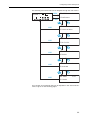
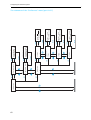
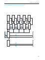
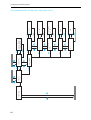
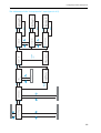
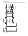
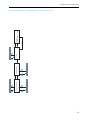
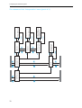
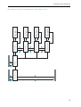
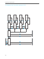
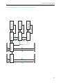
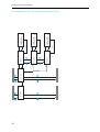
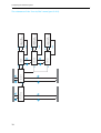
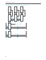
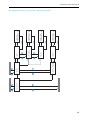
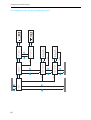
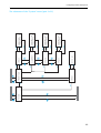
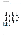
Structuring the SDC 8200 system ............................................................................................................................. 44
The three expansion stages ................................................................................................................................................ 44
Determining maximum cable lengths ............................................................................................................................... 47
Structuring an interpretation system ............................................................................................................................... 47
Selectable modes between or within interpreter booths ............................................................................................. 48
Using external equipment ................................................................................................................................................... 51
Setting up the SDC 8200 system ............................................................................................................................... 52
Preparing the SDC 8200 system components for set up .............................................................................................. 52
Interconnecting the SDC 8200 system components ......................................................................................................
Interconnecting the consoles .......................................................................................................................................
Connecting a cable string to the central unit ............................................................................................................
Interconnecting several central units in master/slave mode
(SDC 8200 CU central units only) ................................................................................................................................
Activating the master/slave mode .............................................................................................................................
Exiting the “slave” mode of a central unit ................................................................................................................
54
54
54
54
55
55
Connecting additional equipment ..................................................................................................................................... 56
Configuring the SDC 8200 system ............................................................................................................................. 60
Introduction to the central unit’s operating menu ........................................................................................................ 60
The start display ............................................................................................................................................................. 60
The six main menus ........................................................................................................................................................ 60
Setting the volume of the consoles’ built-in loudspeakers .......................................................................................... 85
Configuring the conference system ..................................................................................................................................
Automatically initializing all conference consoles ...................................................................................................
Manually initializing all conference consoles ............................................................................................................
Loading the factory-preset default configuration for the conference system ..................................................
Adding a conference console to an already existing configuration .....................................................................
Removing a conference console from an already existing configuration ...........................................................
Reserving a microphone number .................................................................................................................................
Selecting a conference mode ........................................................................................................................................
Setting the speaker limit ...............................................................................................................................................
Adjusting the audio settings for the consoles’ built-in loudspeakers .................................................................
Adjusting the audio settings for the consoles’ microphones ................................................................................
Configuring additional chairman units (Chairmen) .................................................................................................
Deleting the list of chairman units (Chairmen) ........................................................................................................
Configuring additional VIP units (VIP) ........................................................................................................................
Deleting the list of VIP units (VIP) ...............................................................................................................................
Activating/deactivating the special rights of the VIP units (VIP) ........................................................................
Resetting the conference system (Reset) .................................................................................................................
Testing the consoles’ built-in loudspeakers ..............................................................................................................
Testing the consoles’ microphones .............................................................................................................................
Activating/deactivating the flashing of the signal light ring ................................................................................
Configuring the display of the voting options ..........................................................................................................
4
85
85
85
86
86
86
87
88
88
88
89
90
90
91
91
91
91
92
92
92
93
Contents
Configuring the interpretation system ............................................................................................................................. 93
Working with the interpreter configuration ............................................................................................................. 93
Creating a new interpreter configuration .................................................................................................................. 94
Modifying the currently active interpreter configuration ...................................................................................... 95
Loading a previously saved interpreter configuration ............................................................................................ 95
Options .............................................................................................................................................................................. 96
Setting the max. number of interpreter booths/languages .................................................................................. 96
Setting the max. number of interpreter consoles per booth ................................................................................. 96
Configuring the operating mode between booths ................................................................................................... 96
Configuring the operating mode within a booth ...................................................................................................... 97
Configuring the language options for the interpreter booths ............................................................................... 97
Configuring the main target language (A-channel) of a booth ............................................................................ 98
Configuring the second target language (B-channel) of a booth ......................................................................... 98
Enabling the auto-relay interpretation function (Auto-floor) .............................................................................. 99
Half-automatically initializing all interpreter consoles on the central unit ........................................................ 99
Manually assigning an interpreter console an individual booth number ......................................................... 100
Manually assigning an interpreter console an individual desk number (interpreter console number) ..... 101
Displaying the booth and desk number of an interpreter console .................................................................... 102
Adding interpreter consoles to an existing configuration .................................................................................. 102
Loading the factory-preset default configuration for the interpretation system .......................................... 102
Resetting the interpretation system ....................................................................................................................... 103
Configuring the audio inputs and outputs of the central unit and the anaolog output unit ............................. 103
Making a system diagnosis .............................................................................................................................................. 109
Configuring connected additional components ...........................................................................................................
Turning on/off a camera control ..............................................................................................................................
Turning on a connected control panel .....................................................................................................................
Configuring an “ambient sound” console ...............................................................................................................
110
110
110
111
Software, language and license ...................................................................................................................................... 112
If problems occur... .................................................................................................................................................... 114
Accessories ................................................................................................................................................................. 115
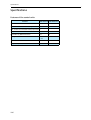
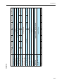
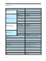
Specifications ............................................................................................................................................................. 116
Features of the central units ........................................................................................................................................... 116
Consoles ............................................................................................................................................................................... 117
Central units ........................................................................................................................................................................ 118
SDC 8200 AO analog output unit .................................................................................................................................... 119
RJ 45 cable ........................................................................................................................................................................... 119
Appendix A: Camera control protocol ..................................................................................................................... 120
Commands: .................................................................................................................................................................... 121
Appendix B: Control panel protocol ........................................................................................................................ 122
The commands sent by the central unit and received by the control panel: ................................................... 123
The commands sent by the control panel and received by the central unit: ................................................... 123
Appendix C: Repeater for the SDC 8200 system ................................................................................................... 124
Manufacturer declarations ....................................................................................................................................... 125
Warranty regulations ........................................................................................................................................................ 125
CE Declaration of Conformity ........................................................................................................................................... 125
FCC Rules .............................................................................................................................................................................. 125
5
Important safety instructions
Important safety instructions
1. Read these instructions for use.
2. Keep these instructions in a safe place.
3. Heed all warnings.
4. Follow all instructions.
5. Do not use near water.
6. Clean only with a dry cloth.
7. Do not block any ventilation openings. Install in accordance with the
manufacturer’s instructions.
8. Do not install near any heat sources such as central heating radiators,
electric heaters, stoves, or other units that produce heat (e.g. amplifiers).
9. This unit is supplied with an IEC mains cable complete with a moulded
mains plug. This is for your safety – do not tamper with the mains. If
the supplied cable does not fit your mains socket, please consult a competent electrician for a replacement cable that matches the power output sockets in your country, or to replace the obsolete socket with one
to current standards.
10.Protect the mains cable from being walked on or pinched, particularly
at plugs, convenience receptacles, and the point where it exits from the
unit.
11.Only use attachments/accessories specified by the manufacturer.
12.Use only with the cart, stand, tripod, bracket, or table specified by the
manufacturer, or sold with the unit. When a cart is used, use caution
when moving the cart/unit combination to avoid injury from tip-over.
13.Unplug during lightning storms or when unused for long periods of
time.
14.Refer all servicing to qualified service personnel. Servicing is required if
the unit has been damaged in any way, such as mains cable or plug
damage, liquid has been spilled, objects have fallen inside, the unit has
been exposed to rain or moisture, does not operate properly or has
been dropped.
6
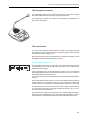
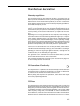
Important safety information
Important safety information
Warning!
To reduce the risk of fire or electric shock, do not expose the unit to rain or
moisture. Do not open the unit as there are potentially dangerous voltages
present inside. Refer all servicing to qualified service personnel.
Caution!
Use only accessories recommended by the manufacturer to avoid fire, electric shock, or other hazards. To prevent the risk of electric shock, do not
remove cover or back. No user serviceable parts inside! Refer all servicing
to qualified service personnel.
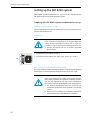
The label shown on the left is attached to the back of the unit. The symbols
on this label have the following meaning:
This symbol is intended to alert the user to the presence of uninsulated
dangerous voltage within the unit’s enclosure that may be of sufficient
magnitude to constitute risk of fire or electric shock.
This symbol is intended to alert the user to the risk of electric shock if the
unit is opened. There are no serviceable parts inside. Refer servicing to
qualified personnel only.
This symbol is intended to alert the user to the presence of important
operating and maintenance instructions in the literature accompanying
this unit.
Warning! Power source
The central unit is a Class 1 unit. It must only be connected to properly
grounded power outlets.
This unit should be operated only from the type of power source indicated
on the marking label. lf you are not sure of the type of power supply to
your building, consult your dealer or local power company.
Disconnection from the mains
To disconnect the unit from the mains, pull the mains plug out of the wall
outlet.
Overload
Do not overload wall outlets and extension cables as this may result in fire
and electric shock.
Objects and liquids
Never push objects of any kind through openings of this unit as they may
touch dangerous voltage points or short-out parts that could result in fire
or electric shock. Never spill liquids of any kind onto the unit. Should a spillage occur, unplug the unit and have it checked by a technician.
7
Important safety information
Maintenance and care
No user serviceable parts inside! Do not attempt to service this unit yourself as opening or removing covers may expose dangerous voltage or other
hazards. Refer all servicing to qualified service personnel.
Clean only with a dry cloth. Do not use detergents or other liquids.
Replacement parts
When replacement parts are required, be sure the service technician uses
replacement parts specified by the manufacturer or those that have the
same characteristics as the original part.
Unauthorized substitutions may result in fire, electric shock, or other hazards.
Safety check
Upon completion of any service or repairs to this unit, ask the service technician to perform safety checks to determine that the product is in proper
operating condition.
The Sennheiser SDC 8200 conference and interpretation system is state of
the art and has been designed to meet the regulations in force. Nevertheless, the individual components of the SDC 8200 conference and interpretation system can cause danger for persons and material assets if:
y the system is not used as intended,
y the system is set up by personnel not familiar with the safety regulations,
y the system is converted or altered incorrectly,
y the safety instructions are not observed.
Attention! High Volume!
This is a professional conference system. Commercial use is subject to the
rules and regulations of the trade association responsible. Sennheiser, as
the manufacturer, is therefore obliged to expressly point out possible
health risks arising from use.
This system is capable of producing sound pressure exceeding 85 dB(A).
85 dB(A) is the sound pressure corresponding to the maximum permissible volume which is by law (in some countries) allowed to affect your hearing for the duration of a working day. It is used as a basis according to the
specifications of industrial medicine. Higher volumes or longer durations
can damage your hearing. At higher volumes, the duration must be shortened in order to prevent hearing damage. The following are sure signs that
you have been subjected to excessive noise for too long a time:
y You can hear ringing or whistling sounds in your ears.
y You have the impression (even for a short time only) that you can no
longer hear high notes.
Warning!
This is a class A product. In a domestic environment this product may cause
radio interference in which case the user may be required to take adequate
measures.
8
SDC 8200 – the digital conference and interpretation system
SDC 8200 – the digital conference and
interpretation system
The new SDC 8200 conference and interpretation system from Sennheiser
utilizes all advantages of digital communications technology and offers its
users a series of important features:
y Decentralized, clear sound reproduction
y Excellent speech intelligibility due to 16-bit audio transmission
y Easy installation and straight-forward operation
y Conference consoles are extremely easy to operate
y Delegate interaction (e.g. with voting sessions)
y Interpretation facility
y Extended functionality
y Possibility of connecting an infrared language distribution system
SDC stands for Sennheiser Digital Conference System – the new generation
of mobile and expandable conference and interpretation equipment.
The SDC 8200 conference and interpretation system is an ideal choice for
both small seminars with up to 20 participants and large international
conferences with a maximum of 1024 participants.
An important feature of the SDC 8200 conference and interpretation system is its modular design. Even if, at first, the system is only required for
small conferences, you can later easily add conference consoles and a software control program. In any case, the conference and interpretation system can:
y be set up quickly, since all consoles are connected in series (single-cable
system),
y be adapted easily to any room and any number of participants.
9
Overview of the components of the SDC 8200 system
Overview of the components of the
SDC 8200 system
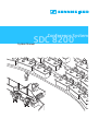
An SDC 8200 conference and interpretation system consists of the following components:
y Conference consoles for delegates and chairmen
y Interpreter consoles
y Central units
y System cables
y If required, a software control for the conference and interpretation system
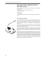
The conference consoles
The conference console features a built-in loudspeaker, allowing the participant to directly hear all audio information, e.g. speeches, presentations
or any other audio material. This decentralized “loudspeaker system”
ensures excellent sound quality at a pleasant volume throughout the
entire room.
The console’s electret microphone transmits every word in excellent audio
quality. The red signal light ring on the microphone serves as an indicator
of who is allowed to take the floor.
The conference consoles are available in six different versions with varying
levels of functions. All conference consoles have voting keys, allowing all
conference participants to participate in voting sessions from their consoles.
The conference consoles can also be operated with a central unit from the
SDC 8000 conference and interpretation system. In this case, the functionality of the conference consoles depends on the functions and features of
the central unit. The conference consoles are connected in series. One cable
string can comprise up to 20 conference consoles and up to six cable
strings (i.e. up to 120 conference consoles) can be connected to a single
central unit. You can, however, interconnect several central units to set up
conference systems with up to 1024 consoles.
10
Overview of the components of the SDC 8200 system
The interpreter consoles
The interpreter console incorporates all functions of a conference console
but offers additional features required by the interpreters.
The interpreter consoles are required if simultaneous interpretation is
offered at a conference.
The central units
You can choose between the SDC 8200 CU central unit for larger and the
SDC 8200 CU-M central unit for smaller conference systems (see “Features
of the central units” on page 116).
Both central units can also be operated with conference consoles from the
SDC 8000 conference and interpretation system.
The SDC 8200 CU central unit
The SDC 8200 CU central unit is the core of the SDC 8200 conference and
interpretation system and, at the same time, serves as an interface for
additional audio systems.
Via the operating menu of the SDC 8200 CU central unit, the conference
and interpretation system can be configured for any room, any number of
participants and any conference use.
The central unit serves to manage the entire conference and interpretation
system.
On the SDC 8200 CU central unit, you can choose between ten conference
modes. However, the selection of some of the conference modes only
makes sense if your conference and interpretation system is PC controlled.
The SDC 8200 CU central unit has a built-in power supply for powering up
to 120 conference consoles. For larger conference systems, up to 12 central units can be interconnected.
The interpretation capacity of the central unit is 28 languages. Two different licenses are available for eight or 28 interpretation channels. The floor
channel and four interpretation channels can be operated license-free.
11
Overview of the components of the SDC 8200 system
The SDC 8200 CU-M central unit
The SDC 8200 CU-M central unit is the core of the SDC 8200 conference and
interpretation system and, at the same time, serves as an interface for
additional audio systems.
Via the operating menu of the SDC 8200 CU-M central unit, the conference
and interpretation system can be configured for any room, any number of
participants and any conference use.
The central unit serves to manage the entire conference and interpretation
system.
On the SDC 8200 CU-M central unit, you can choose between ten conference modes. However, the selection of some of the conference modes only
makes sense if your conference and interpretation system is PC controlled.
The SDC 8200 CU-M central unit has a built-in power supply for powering
up to 50 conference consoles. However, it is not possible to interconnect
several SDC 8200 CU-M central units in order to realize larger conference
systems.
The floor channel and four interpretation channels can be operated
license-free.
The SDC 8200 AO analog output unit
The analog output unit has nine audio outputs to which you can connect:
y an infrared language distribution system,
y PA systems,
y recording units, etc.
One analog output unit can output the floor channel and up to eight additional interpretation channels. The analog output unit can only be connected to the SDC 8200 CU central unit. Up to four analog output units can
be connected to the SDC 8200 CU central unit using a conference bus cable.
Power for the analog output units is supplied via the SDC 8200 CU central
unit.
The system cables
Power supply of the conference consoles is via the system cables which
also transmit the digital audio and status information.
The software control
The optional software control allows a conference manager to control the
entire conference via a PC. In contrast to controlling the conference via the
central unit, the software control provides several extra functions:
y Additional functions for controlling the microphones:
Via the computer screen, the conference manager can easily monitor
which participants have made a request to speak, which participants are
currently speaking, etc. All participants can be identified and displayed
by name. Individual conference consoles can be directly activated or
deactivated by clicking the mouse key.
12
Overview of the components of the SDC 8200 system
y Display of voting results as diagrams:
The results of votings can be presented graphically and can, for example,
be displayed via a connected projector. In addition, it is possible to take
voting sessions with chip cards. Chip cards make sure that only those
who have a chip card have access to the voting function.
y Configuration of special conference consoles:
The conference manager can configure more than one chairman unit as
well as VIP units.
y Interpreter management software:
This software module allows the conference manager to quickly and easily configure the interpreter booths and interpreter consoles (i.e. assign
a language to the A-channel and B-channel of an interpreter console,
choose the operating mode between and within the interpreter booths,
etc.).
y Delegate database:
The delegate database allows the conference manager to centrally manage delegate information such as name, organization, etc. During the
conference, this information is displayed on the computer screen, allowing the conference manager to identify the participants who are currently speaking or those who wish to make a contribution by name. It is
also possible to use the information contained on the chip cards.
The technology used
Both the control and sound transmission of the SDC 8200 conference and
interpretation system are fully digital, resulting in excellent audio. The language channels are transmitted within a frequency range of 100 Hz to
14 kHz at 16-bit resolution.
The conference consoles are connected to each other and to the central
unit by means of system cables.
13
The components of the SDC 8200 system in detail
The components of the SDC 8200 system
in detail
The components described on the following pages are available for the
SDC 8200 conference and interpretation system. The components you
require depend on the desired size and use of the SDC 8200 system.
Your conference and interpretation system can comprise the following
consoles:
y two types of conferences consoles
– the delegate units for the conference participants
– the chairman unit for the chairman
y the interpreter consoles
In addition, your conference and interpretation system must comprise:
y at least one central unit
Optionally, you can connect the following components:
y an analog output unit
y a control panel
y a special “ambient sound” conference console
The consoles
Six conference console versions with varying levels of functions as well as
an interpreter console are available.
All consoles feature:
y a built-in loudspeaker via which the floor channel is output
y a microphone key
for activating the microphone
y a microphone – if the microphone is active, the red signal light ring and
the “Microphone active” LED light up permanently
y a headphone connection with headphone volume control
y voting keys with LEDs (either 3 or 5 voting keys, depending on the console version)
The chairman units (SDC 8200 C, SDC 8200 CC and SDC 8200 CV) additionally feature:
y a priority key
for turning off all active delegate units
y a NEXT key
for assigning the “speaking right” to the next participant
who has made a request to speak (SDC 8200 C and SDC 8200 CC only).
Conference consoles with channel selection keys (SDC 8200 DC, SDC 8200 CC,
SDC 8200 DV and SDC 8200 CV) feature:
y a 2-digit LED channel display for displaying the selected interpretation
channel and two channel selection keys (“ 왖” and “ 왔”) for selecting the interpretation channel.
The selected interpretation channel is output via connected headphones.
14
The components of the SDC 8200 system in detail
Conference consoles with display and chip card slot (SDC 8200 CV and
SDC 8200 DV) feature:
y a chip card slot for delegate identification
y a dot matrix display (122 x 32 dots) for displaying voting options, voting results and other important information
The interpreter console features:
y special “interpretation” functions
y a muting function (MUTE key)
y tone controls for volume, middle and treble of the headphones and a volume control for the loudspeaker
y a chip card slot
The six conference console versions and the interpreter console are illustrated in detail on the following pages.
15
The components of the SDC 8200 system in detail
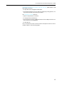
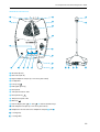
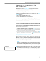
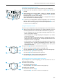
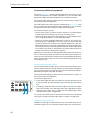
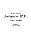
SDC 8200 D conference unit
22
IN socket (RJ 45)
OUT socket (RJ 45)
Right headphone output (3.5 mm mono jack socket)
Loudspeaker
Red signal light ring
Microphone
“Microphone active” LED
Microphone key
“Request to speak” LED
Headphone volume control for left headphone output Left headphone output (3.5 mm mono jack socket)
Headphone volume control for right headphone output 3 voting keys
3 voting LEDs
16
22
The components of the SDC 8200 system in detail
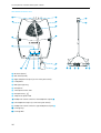
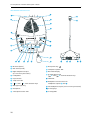
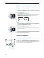
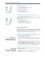
SDC 8200 C chairman unit
IN socket (RJ 45)
OUT socket (RJ 45)
Right headphone output (3.5 mm mono jack socket)
Loudspeaker
Priority key
Red signal light ring
Microphone
“Microphone active” LED
Microphone key
“Request to speak” LED
NEXT key
Left headphone output (3.5 mm mono jack socket)
Headphone volume control for headphone outputs and 3 voting keys
3 voting LEDs
17
The components of the SDC 8200 system in detail
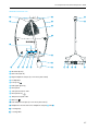
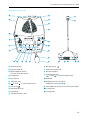
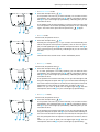
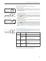
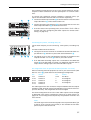
SDC 8200 DC conference unit
22
IN socket (RJ 45)
OUT socket (RJ 45)
Right headphone output (3.5 mm mono jack socket)
Loudspeaker
Red signal light ring
Microphone
“Microphone active” LED
Microphone key
“Request to speak” LED
Channel display with “
왖” and “
왔” channel selection keys
Headphone volume control for left headphone output Left headphone output (3.5 mm mono jack socket)
Headphone volume control for right headphone output 3 voting keys
3 voting LEDs
18
22
The components of the SDC 8200 system in detail
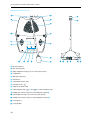
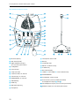
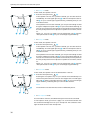
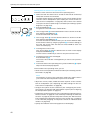
SDC 8200 CC chairman unit
IN socket (RJ 45)
OUT socket (RJ 45)
Right headphone output (3.5 mm mono jack socket)
Loudspeaker
Priority key
Red signal light ring
Microphone
“Microphone active” LED
Microphone key
“Request to speak” LED
NEXT key
Channel display with “
왖” and “
왔” channel selection keys
Left headphone output (3.5 mm mono jack socket)
Headphone volume control for headphone outputs and 3 voting keys
3 voting LEDs
19
The components of the SDC 8200 system in detail
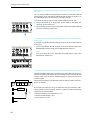
SDC 8200 DV conference unit
22
IN socket (RJ 45)
Microphone key
OUT socket (RJ 45)
“Request to speak” LED
Right headphone output
(3.5 mm mono jack socket)
Dot matrix display
Loudspeaker
Channel display with
“ 왖” and “ 왔” channel selection keys
Chip card slot
VOTE LED
“Chip card” LED
“
왖” and “
왔” menu selection keys
22
Headphone volume control for
headphone outputs and Red signal light ring
Left headphone output (3.5 mm mono jack socket)
Microphone
5 voting keys
“Microphone active” LED
5 voting LEDs
20
The components of the SDC 8200 system in detail
SDC 8200 CV chairman unit
22
IN socket (RJ 45)
Microphone key
OUT socket (RJ 45)
“Request to speak” LED
Right headphone output
(3.5 mm mono jack socket)
Dot matrix display
Loudspeaker
Channel display with
“ 왖” and “ 왔” channel selection keys
Chip card slot
VOTE LED
“Chip card” LED
Headphone volume control for
headphone outputs and “
왖” and “
왔” menu selection keys
22
Priority key
Left headphone output (3.5 mm mono jack socket)
Red signal light ring
5 voting keys
Microphone
5 voting LEDs
“Microphone active” LED
21
The components of the SDC 8200 system in detail
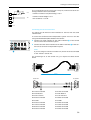
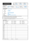
SDC 8200 ID interpreter console
22
IN socket (RJ 45)
“Microphone active” LED
OUT socket (RJ 45)
MIC key
Right headphone output
(3.5 mm mono jack socket)
“Initialized” LED
Loudspeaker
Chip card slot
“Chip card” LED
“Channel” LEDs “A” and “B“
Channel keys “A” and “B“
ENGAGED LEDs “A” and “B“
MESSAGE key
MUTE key
Red signal light ring
Microphone
22
22
RELAY 1 to RELAY 3 keys
LS CHAN. key
Dot matrix display
“MENU 왖” and “MENU 왔” menu selection keys
AUTOFLOOR LED
Loudspeaker volume control
Tone controls (volume, middle and treble)
for headphone outputs and Left headphone output (3.5 mm mono jack socket)
Headset output (3.5 mm stereo jack socket)
The components of the SDC 8200 system in detail
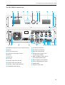
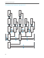
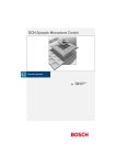
The SDC 8200 CU central unit
Headphone output (3.5 mm mono jack socket)
SLAVE IN socket (RJ 45)
Display
SLAVE OUT socket (RJ 45)
F1 to F3 function keys
DATA OUT socket (RJ 45)
Jog wheel for selecting the menus
AUX OUT audio outputs 1 to 6
(15-pole sub-D socket)
EXIT key
ENTER key
Air vents
AUX IN 1 audio input (XLR-3F)
AUX IN 2 audio input (XLR-3F)
AUX OUT 1 audio output (XLR-3M)
MASTER OUT socket (RJ 45)
PORT 1 to PORT 6 sockets (RJ 45)
for connecting cable strings
COM 1 to COM 3 serial interfaces
Fan for integrated power supply
POWER switch
Socket for mains cable
23
The components of the SDC 8200 system in detail
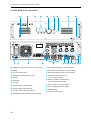
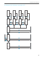
The SDC 8200 CU-M central unit
쐋
Headphone output (3.5 mm mono jack socket)
SLAVE IN socket (RJ 45) (not connected)
Display
SLAVE OUT socket (RJ 45) (not connected)
F1 to F3 function keys
DATA OUT socket (RJ 45) (not connected)
Jog wheel for selecting the menus
AUX OUT audio outputs 1 to 6
(15-pole sub-D socket)
EXIT key
ENTER key
Air vents
AUX IN 1 audio input (XLR-3F)
AUX IN 2 audio input (XLR-3F)
AUX OUT 1 audio output (XLR-3M)
MASTER OUT socket (RJ 45) (not connected)
24
PORT 1 to PORT 6 sockets (RJ 45)
for connecting cable strings
COM 1 to COM 3 serial interfaces
Fan for integrated power supply
POWER switch
Socket for mains cable
The components of the SDC 8200 system in detail
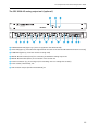
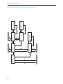
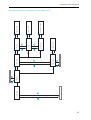
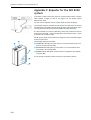
The SDC 8200 AO analog output unit (optional)
POWER SUPPLY LED (lights up, if power is supplied to the SDC 8200 AO)
SYNC. LED (lights up, if the data exchange between the central unit and the SDC 8200 AO functions correctly)
FLOOR LED (lights up, if the floor channel is being used)
DIGITAL BUS OUT socket (RJ 45) for connecting an additional analog output unit
DIGITAL BUS IN socket (RJ 45) for connection of the central unit
Phoenix connector (e.g. for turning on/off a recording unit via a voltage-free contact)
Phono socket (unbalanced), 10x
XLR-3M audio output (transformer balanced), 9x
25
The components of the SDC 8200 system in detail
The system cables
The system cables required for your planned conference and interpretation system must be ordered separately. The system cables are available
with lengths of 2 m, 3 m, 5 m, 10 m, 20 m and 50 m.
Via the system cables, you can:
y interconnect the conference and interpreter consoles,
y interconnect up to 10 central units for setting up a large conference and
interpretation system,
y connect an SDC 8200 AO analog output unit to the central unit,
y connect cable strings to the central unit.
The system cables must meet the following specifications:
Shielded RJ 45 modular plug, cat 5(e)
Black cable booth with clip protector
Round STP cable, cat 5(e), 24AWG
Grey cable booth with clip protector
26
Operating the components of the SDC 8200 system
Operating the components of the
SDC 8200 system
Depending on the type of delegate unit, conference participants can:
y listen, take the floor or make a request to speak,
y receive simultaneous interpretation,
y participate in voting sessions.
In addition to the functions and features of the delegate units, the chairman unit allows to:
y start a voting session (SDC 8200 CV only),
y mute all active delegate units (priority function).
The interpreter consoles are exclusively used by the interpreters.
The central unit is operated by the conference manager – either directly or
via an optional PC with software control.
Turning the conference and interpretation system on/off
You turn the conference and interpretation system on by turning on the
central unit(s) (see the following sections). In doing so, all connected conference consoles are also turned on.
y The central units are turned on if the POWER switch is set to position
“I” and the start display is shown on the LC display.
y The central units are turned off if the POWER switch is set to position
“0” and the start display is not shown on the LC display.
y The conference consoles are turned on if the “Microphone active” LED lights up or flashes after the microphone key
has been pressed.
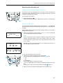
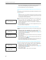
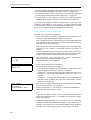
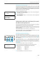
Turning on the central unit for the first time
When turning on the central unit for the first time, the text “Init
Refused” is shown on the displays of the conference consoles connected
to the central unit. The conference consoles cannot be detected by the central unit, since they have not yet been assigned a microphone number.
Your conference system is not yet operational.
Note!
Once you have configured your conference and interpretation system,
the configuration will be retained in memory on turn-off. When turning
on the central unit again, your conference system is immediately operational.
Conference
7
Initialise Units
왘 First, initialize the conference consoles in order to assign each console
an internal microphone number. You can choose between two initialization modes: automatic (see page 85) and manual (see page 85) initialization.
27
Operating the components of the SDC 8200 system
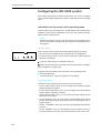
Turning interconnected SDC 8200 CU central units on/off
When turning on a conference and interpretation system with several
SDC 8200 CU central units, it is important that the central units are turned
on in the correct order.
왘 First turn on the “master” central unit.
왘 Then turn on the “slave” central units in the order in which they are
connected to the “master”.
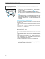
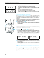
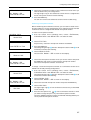
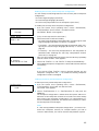
To turn a central unit on:
왘 Set the POWER switch to position “I”.
The consoles which are powered via this central unit are ready for operation as soon as they are initialized.
The start display is shown on the LC display of this central unit.
>Volume =
P1
P2
P3
P4
P5
P6
Note!
It is, however, possible to simultaneously turn on interconnected central units via a switchable multiple socket.
To turn a central unit off:
왘 Set the POWER switch to position “0”.
The display goes off. All consoles which were powered via this central
unit are also turned off.
Note!
The central units are not disconnected from the mains when they are
turned off. To disconnect the central units from the mains, pull their
mains plugs out of the wall outlets.
Operating the delegate units
Taking the floor / Making a request to speak
In order to take the floor or make a request to speak, you have to press the
microphone key
. Depending on the conference mode chosen (1. to
10., see following section), you can either take the floor immediately or
you have to wait until your microphone is turned on.
28
Operating the components of the SDC 8200 system
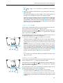
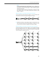
1. In “Direct Access” mode:
왘 Press the microphone key
.
If the speaker limit has not yet been reached, you can take the floor
immediately. The red signal light ring and the “Microphone active”
LED on your console light up permanently, indicating that you can
now take the floor.
If the speaker limit has been reached, you have to wait until one of the
current speakers has finished speaking and passes on the “speaking
right”. You then have to press the microphone key
again.
2. In “Fifo” mode:
In this mode, the speaker limit is 1.
왘 Press the microphone key
.
Pressing the microphone key on your console will automatically turn
off the microphone of the previous speaker (“first-in-first-out” principle). The red signal light ring and the “Microphone active” LED on
your console light up permanently, indicating that you can now take
the floor.
Note!
The chairman units and VIP units remain unaffectedly active.
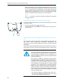
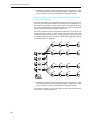
3. In “Group 1” mode:
In this mode, the speaker limit is 1.
왘 Press the microphone key
.
If no other participant is currently speaking, you can take the floor
immediately. The red signal light ring and the “Microphone active”
LED on your console light up permanently, indicating that you can
now take the floor.
If the speaker limit has been reached, you will join the waiting list and
the green “Request to speak” LED on your console starts flashing. As
soon as the active microphone is turned off, the microphone of the first
participant from the request-to-speak list is turned on, and so on.
When it is your turn to speak, the red signal light ring and the
“Microphone active” LED on your console light up permanently.
4. In “Group 2” mode:
In this mode, the speaker limit is 2.
왘 Press the microphone key
.
If the speaker limit has not yet been reached, you can take the floor
immediately. The red signal light ring and the “Microphone active”
LED on your console light up permanently, indicating that you can
now take the floor.
If the speaker limit has been reached, you will join the waiting list and
the green “Request to speak” LED on your console starts flashing. As
soon as one of the active microphones is turned off, the microphone of
the first participant from the request-to-speak list is turned on, and so
on.
When it is your turn to speak, the red signal light ring and the
“Microphone active” LED on your console light up permanently.
29
Operating the components of the SDC 8200 system
5. In “Group 3” mode:
In this mode, the speaker limit is 3.
왘 Press the microphone key
.
If the speaker limit has not yet been reached, you can take the floor
immediately. The red signal light ring and the “Microphone active”
LED on your console light up permanently, indicating that you can
now take the floor.
If the speaker limit has been reached, you will join the waiting list and
the green “Request to speak” LED on your console starts flashing. As
soon as one of the active microphones is turned off, the microphone of
the first participant from the request-to-speak list is turned on, and so
on.
When it is your turn to speak, the red signal light ring and the
“Microphone active” LED on your console light up permanently.
6. In “Group 4” mode:
In this mode, the speaker limit is 4.
왘 Press the microphone key
.
If the speaker limit has not yet been reached, you can take the floor
immediately. The red signal light ring and the “Microphone active”
LED on your console light up permanently, indicating that you can
now take the floor.
If the speaker limit has been reached, you will join the waiting list and
the green “Request to speak” LED on your console starts flashing. As
soon as one of the active microphones is turned off, the microphone of
the first participant from the request-to-speak list is turned on, and so
on.
When it is your turn to speak, the red signal light ring and the
“Microphone active” LED on your console light up permanently.
7. In “Override” mode:
In this mode, the speaker limit is variable between 1 and 15.
왘 Press the microphone key
.
Pressing the microphone key on your console will automatically turn
off the microphone which is active for the longest time. The red signal
light ring and the “Microphone active” LED on your console light
up permanently, indicating that you can now take the floor.
Note!
The chairman units and VIP units remain unaffectedly active.
8. In “No request” mode:
For this mode to function, the SDC 8200 system must be PC controlled.
In “No request” mode, you have to “apply” for a comment and wait until
the conference manager turns on your microphone. The conference manager has total control of the microphones.
30
Operating the components of the SDC 8200 system
Note!
You cannot “apply” for a comment by pressing the microphone
key
.
왘 Signal your intention to take the floor e.g. by raising your hand or giving another sign.
The conference manager can either assign you the “speaking right” by
turning on your microphone or ignore your request to speak.
When the conference manager turns on you microphone, the red signal
light ring and the “Microphone active” LED on your console light
up permanently. When the conference manager withdraws the “speaking right” from you, the red signal light ring and the “Microphone
active” LED on your console go off.
9. In “With request” mode:
In this mode, the SDC 8200 system can be controlled either by the chairman or via the PC. You can cancel your request to speak.
The chairman can use the NEXT key
(SDC 8200 C and SDC 8200 CC) or
the menu selection keys
(SDC 8200 CV) for assigning the “speaking
right” in the order of application.
If the SDC 8200 system is PC controlled, the “speaking right” can be
assigned independently of the order of application.
왘 Press the microphone key
to “apply” for a comment.
The green “Request to speak” LED on your console starts flashing.
The chairman or the conference manager can either assign you the
“speaking right” by turning on your microphone or ignore your request
to speak.
When the chairman or the conference manager turns on your microphone, the red signal light ring and the “Microphone active” LED on your console light up permanently and the green “Request to
speak” LED goes off. When the chairman or the conference manager
withdraws the “speaking right” from you, the red signal light ring and the “Microphone active” LED on your console go off.
Note!
You can cancel your request to speak by pressing the microphone key
once more.
10.In “With Req. No clear” mode:
In this mode, the SDC 8200 system can be controlled either by the chairman or via the PC. You cannot cancel your request to speak.
The chairman can use the NEXT key
(SDC 8200 C and SDC 8200 CC) or
the menu selection keys
(SDC 8200 CV) for assigning the “speaking
right” in the order of application.
If the SDC 8200 system is PC controlled, the “speaking right” can be
assigned independently of the order of application.
왘 Press the microphone key
to “apply” for a comment.
The green “Request to speak” LED on your console starts flashing.
The chairman or the conference manager can either assign you the
“speaking right” by turning on your microphone or ignore your request
to speak.
31
Operating the components of the SDC 8200 system
When the chairman or the conference manager turns on your microphone, the red signal light ring and the “Microphone active” LED on your console light up permanently and the green “Request to
speak” LED goes off. When the chairman or the conference manager
withdraws the “speaking right” from you, the red signal light ring and the “Microphone active” LED on your console go off.
Note!
You cannot cancel your request to speak by pressing the microphone
key
once more!
Turning off the microphone / Cancelling a request to speak
To turn off the microphone when you have finished speaking or to cancel
a request to speak:
왘 Press the microphone key
once more.
The red signal light ring and the “Microphone active” LED on your
console go off.
Adjusting the volume of the headphones connected to a conference console
With conference consoles which feature two headphone outputs but only
one volume control (SDC 8200 C, SDC 8200 CC, SDC 8200 DV and
SDC 8200 CV), the volume control adjusts the volume for both connected
headphones.
The volume is steplessly adjustable and the volume control has no stop. At
each system start-up, the volume is automatically reset to a medium level.
Caution!
Hearing damage due to high volumes!
This is a professional conference system. Commercial use
is subject to the rules and regulations of the trade association responsible. Sennheiser, as the manufacturer, is
therefore obliged to expressly point out possible health
risks arising from use.
This system is capable of producing sound pressure
exceeding 85 dB(A). 85 dB(A) is the sound pressure corresponding to the maximum permissible volume which is
by law (in some countries) allowed to affect your hearing
for the duration of a working day. It is used as a basis
according to the specifications of industrial medicine.
Higher volumes or longer durations can damage your
hearing. At higher volumes, the duration must be shortened in order to prevent hearing damage. The following
are sure signs that you have been subjected to excessive
noise for too long a time:
y You can hear ringing or whistling sounds in your ears.
y You have the impression (even for a short time only)
that you can no longer hear high notes.
32
Operating the components of the SDC 8200 system
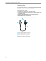
To adjust the volume of the headphones connected to your conference
console:
22
왘 Connect Sennheiser mono headphones to the 3.5 mm mono jack socket
( and/or ).
왘 First, use the headphone volume control ( and/or ) to reduce the
headphone volume to the minimum.
왘 Put on the headphones and slowly set the volume to a medium level.
Selecting an interpretation channel
If your console is equipped with channel selection keys (SDC 8200 DC,
SDC 8200 CC, SDC 8200 DV and SDC 8200 CV), you can choose between the
floor channel and the offered interpretation channels.
To select an interpretation channel:
왘 Connect Sennheiser mono headphones to your conference console.
왘 Press the “ 왖” or “ 왔” channel selection key .
The selected interpretation channel is output via your headphones.
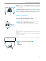
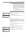
Voting
You can participate in voting sessions which have to be started by the
chairman.
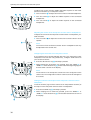
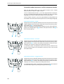
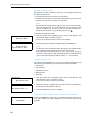
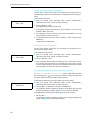
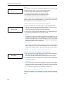
There are two voting modes (“Vote 1 of 3” and “Vote 1 of 5”) which offer
different voting options.
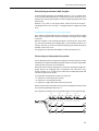
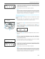
Vote 1 of 3
In “Vote 1 of 3” mode, you can vote “Yes” (+) or “No” (-) or abstain (0):
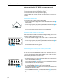
Mic N.: 1024
VOTE 1 OF 5
1
2
3
4
5
왘 To cast your vote, press the corresponding key .
+: Yes
-: No
0: Abstention
Your vote is counted. If voting is not secret, the corresponding voting
LED lights up.
33
Operating the components of the SDC 8200 system
Vote 1 of 5
In “Vote 1 of 5” mode, you have the choice of five options (1 to 5):
Mic N.: 1024
VOTE 1 OF 5
1
2
3
4
5
왘 To cast your vote, press the corresponding key below the display.
Your vote is counted.
If voting is not secret, the corresponding voting LED lights up.
After the voting session, the result of the vote is shown on the displays
of the consoles.
Note!
If your conference system comprises conference consoles with three
and five voting keys and you carry out a voting in “Vote 1 of 5” mode,
this will falsify the voting results. In this case, always choose the “Vote
1 of 3” mode.
Using the chip card slot of a conference console
If the conference consoles feature a chip card slot and if your system is PC
controlled, you can:
y make sure that only authorized delegates can participate in voting sessions.
y take roll-call votes, i.e. you can see the name of each conference participant and his or her voting position.
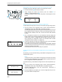
Operating the VIP units
VIP units are special delegate units which have the “rights” of a chairman
unit.
y With a VIP unit, you can take the floor at any time, regardless of the conference mode and without first having to be assigned the “speaking
right”.
y If the chairperson presses the priority key , all active conference consoles – except for the VIP units – are turned off. The chairperson cannot
withdraw the “speaking right” from you.
y The VIP units are operated in the same way as the delegate units.
Note!
You can configure VIP units either via the central unit’s operating menu
(see “Configuring additional VIP units (VIP)” on page 91) or via the
software control of the conference system.
34
Operating the components of the SDC 8200 system
Operating the chairman unit
Turning all active conference consoles off (priority)
All chairman units are equipped with a priority function, allowing the
chairman to stop a discussion any time. By using this function, all active
conference consoles are turned off.
To use the priority function:
왘 Press the priority key .
All active conference consoles – except for the VIP units – are turned off.
Starting a voting session
A voting session can be started by either the chairman or – provided that
a PC with software control is connected to the central unit – the conference
manager.
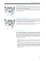
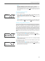
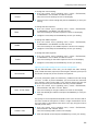
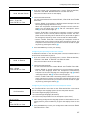
With the SDC 8200 CV chairman unit with voting function, you can start a
voting session as follows:
왘 Choose one of the two voting modes “1 of 3” or “1 of 5” by pressing
the corresponding key below the display.
Mic N.: 0001
START VOTE
1 of 3
1 of 5
Note!
If your conference system comprises conference consoles with three
and five voting keys and you carry out a voting in “Vote 1 of 5” mode,
this will falsify the voting results. In this case, always choose the “Vote
1 of 3” mode.
Mic N.: 0001
VOTE 1/3
000
000
YES
ABS
Depending on the voting mode chosen, your display looks like one of
the two displays shown on the left.
000
NO
Mic N.: 0001
VOTE 1/5
PRIOR=STOP
000
000
000
000
000
1
2
3
4
5
왘 Ask the participants to cast their vote.
왘 Cast your own vote by pressing one of the keys .
With the SDC 8200 C and SDC 8200 CC conference consoles:
+: Yes
-: No
0: Abstention
With the SDC 8200 CV conference console:
“1” to “5”: depending on the respective assignment shown on the display
If voting is not secret, the corresponding voting LED lights up.
왘 Make sure that all conference participants have cast their vote.
35
Operating the components of the SDC 8200 system
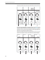
왘 To stop the voting session:
Mic N.: 0001
VOTE 1/3
245
002
YES
ABS
– Stop “Vote 1/3” by pressing the key below “STOP”.
The voting result is shown on the consoles with display.
Press the key below “END” to clear the voting result from the displays.
150
NO
Mic N.: 0001
RESULTS
PRIOR=END
032
041
009
015
625
1
2
3
4
5
– Stop “Vote 1/5” by pressing the priority key .
The voting result is shown on the consoles with display.
Press the priority key again to clear the voting result from the displays.
Assigning a participant the “speaking right”
If – in “With Request” or “With Req. No Clear” mode – a participant presses
the microphone key
on his console, he makes a request to speak. All
participants who have made a request to speak will join a request-tospeak list.
To assign the first participant from the request-to-speak list the “speaking
right” using the SDC 8200 C or SDC 8200 CC chairman unit:
왘 Press the NEXT key
.
The next participant from the request-to-speak list is assigned the
“speaking right”.
To assign the first participant from the request-to-speak list the “speaking
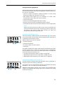
right” using the SDC 8200 CV chairman unit:
왘 Press the “ 왖“ und „ 왔“ menu selection key.
The first three consoles from which a request to speak has been made
are shown on the displays of all conference consoles. If you do not use
chip cards, the microphone numbers are displayed; if you use chip
cards, the delegate names stored on the chip cards are displayed (see
also next section). In addition, “NEXT” is shown in the lower left corner
of the display.
MIC N.: 0001
REQUEST:
MIC N.0657
MIC N.0421
NEXT
MIC N.0010
MIC N.: 0001
REQUEST:
ARCHER
VAN BUUREN
NEXT
TAKAHASHI
왘 On the left-hand side below the display, press the key which is assigned
to the text “NEXT”.
The next particpant from the request-to-speak list is assigned the
“speaking right”.
Showing the request-to-speak list on the displays of the conference consoles
If – in “With Request” or “With Req. No Clear” mode – a participant presses
the microphone key
on his console, he makes a request to speak. All
participants who have made a request to speak will join a request-tospeak list.
36
Operating the components of the SDC 8200 system
If the SDC 8200 CV chairman unit is configured so that the request-tospeak list is shown on the display, this request-to-speak list is also shown
on all SDC 8200 DV conference consoles.
To configure the SDC 8200 CV chairman unit so that the request-to-speak
list is shown on the displays of all conference consoles:
왘 On the SDC 8200 CV chairman unit, press the “ 왖” or “ 왔” menu
selection key.
The request-to-speak list is shown on the displays of all SDC 8200 DV
and SDC 8200 CV conference consoles. The microphone numbers of the
consoles from which a request to speak has been made are not shown
on the displays of the SDC 8200 CV conference consoles.
Operating the interpreter consoles
Adjusting the volume and the middle and treble response of the headphones connected to the interpreter console
If you have connected two headphones to the interpreter console, the volume control adjusts the volume for both headphones. At each system
start-up, the volume is automatically reset to a medium level.
Caution!
Hearing damage due to high volumes!
This is a professional conference system. Commercial use
is subject to the rules and regulations of the trade association responsible. Sennheiser, as the manufacturer, is
therefore obliged to expressly point out possible health
risks arising from use.
This system is capable of producing sound pressure
exceeding 85 dB(A). 85 dB(A) is the sound pressure corresponding to the maximum permissible volume which is
by law (in some countries) allowed to affect your hearing
for the duration of a working day. It is used as a basis
according to the specifications of industrial medicine.
Higher volumes or longer durations can damage your
hearing. At higher volumes, the duration must be shortened in order to prevent hearing damage. The following
are sure signs that you have been subjected to excessive
noise for too long a time:
– You can hear ringing or whistling sounds in your
ears.
– You have the impression (even for a short time
only) that you can no longer hear high notes.
37
Operating the components of the SDC 8200 system
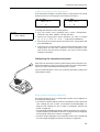
To adjust the volume and the middle and treble response of the headphones connected to your interpreter console:
왘 Turn the control to adjust the volume of the connected headphones.
왘 Turn the control to adjust the middle response of the connected
headphones.
왘 Turn the control to adjust the treble response of the connected
headphones.
Adjusting the volume of the interpreter consoles’ built-in loudspeakers
To adjust the volume of the interpreter console’s built-in loudspeaker, proceed as follows:
왘 Turn the control to adjust the volume of the console’s built-in loudspeaker.
Note!
The volume of the conference consoles’ built-in loudspeakers can only
be adjusted on the central unit!
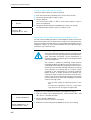
Configuring the B-channel of an interpreter console
If you interpret into a second language, but also if you interpret for other
interpreters who take the relay (Auto-floor), configure the B channel of
your console as follows:
왘 Press the “B-channel” key and keep it pressed.
왘 While keeping the “B-channel” key pressed, press the “MENU 왖” or
“MENU 왔” menu selection key until the desired target language for
the B-channel is shown on the display.
Note!
The A-channel of an interpreter console has to be configured via the
central unit. The configuration of the A-channel cannot be changed on
the console.
Setting the channel to be output via the interpreter console’s built-in
loudspeaker
To set the channel (e.g. the floor channel or an interpretation channel) to
be output via the interpreter console’s built-in loudspeaker:
왘 Press the LS CHAN. key and keep it pressed.
왘 While keeping the LS CHAN key pressed, press the “MENU 왖” or
“MENU 왔” menu selection key until the desired channel is shown on
the display.
38
Operating the components of the SDC 8200 system
Selecting an interpretation channel
To select an interpretation channel to be output via your headphones:
왘 Press one of the keys RELAY 1, RELAY 2 or RELAY 3 and keep it
pressed.
왘 While keeping one of the keys RELAY 1, RELAY 2 or RELAY 3 pressed,
press the “MENU 왖” or “MENU 왔” menu selection key until the
desired language is shown on the display.
The pressed key RELAY 1, RELAY 2 or RELAY 3 is assigned the interpretation channel with the selected language.
왘 To listen to the interpretation channel assigned to one of the keys
RELAY 1, RELAY 2 or RELAY 3, press the corresponding key .
The LED next to the key lights up. The selected interpretation channel
is output via your headphones.
Using the interpreter console
As soon as your interpreter console is configured, you can use it as follows:
왘 Make sure that the correct channel for the target language is set (see
“Switching between the A-channel and the B-channel” on page 39):
– If you interpret into the main target language assigned to your
booth, choose the A-channel.
– If you interpret into a target language not assigned to your booth,
choose the B-channel.
In this case, make sure that the B-channel is configured to the language into which you interpret (see “Configuring the B-channel of an
interpreter console” on page 38)!
– If you interpret a “rare” language into a language of which the other
interpreters have a complete understanding and from which they
then interpret into their respective languages (Auto-floor), also
choose the B-channel.
The green LEDs indicate the selected channel (A or B).
왘 Make sure that the selected channel is not being used!
The red “ENGAGED” LED of the selected channel must not light up!
왘 Press the MIC key and start interpreting.
The red LED of the selected channel lights up.
왘 Press the MIC key once more to stop interpreting.
The red LED of the selected channel goes off.
Switching between the A-channel and the B-channel
If you interpret into a second language, you have to switch from the Achannel to the B-channel.
To switch to the B-channel:
왘 Press the “B-channel” key .
The green LED next to the “B-channel” key lights up.
To switch to the A-channel:
왘 Press the “A-channel” key .
The green LED next to the “A-channel” key lights up.
39
Operating the components of the SDC 8200 system
Muting the microphone of the interpreter console
To mute your microphone:
왘 Press the MUTE key and keep it pressed.
Your microphone is muted.
To turn on your microphone again:
왘 Release the MUTE key .
Your mirophone is turned on again.
Displaying text messages on the interpreter console’s display
If a PC with software control is connected to the central unit, you can
receive text messages from the central unit.
If you have received a text message, the MESSAGE LED on your interpreter
console lights up.
왘 Press the MESSAGE key .
The text message is shown on the display.
왘 Press the MESSAGE key again.
The display returns to the standard display.
Operating the central unit
Before a conference starts, you have to configure your entire conference
and interpretation system via the central unit’s operating menu (see “Configuring the SDC 8200 system” on page 60); it is, however, possible to
make changes to individual settings during a conference.
Adjusting the volume of the consoles’ built-in loudspeakers
Adjust the volume of the consoles’ built-in loudspeakers so that all participants can clearly hear all audio information:
왘 Turn the jog wheel on the central unit.
The volume of the consoles’ built-in loudspeaker is increased or
reduced. The bars on the start display indicate the set volume level.
Note!
The conference participants cannot adjust the volume of their consoles’
built-in loudspeakers! However, each participant can individually
adjust the headphone volume on his or her console.
The interpreters can individually adjust both the volume of their consoles’
built-in loudspeakers and the volume of the connected headphones.
Restarting the conference and interpretation system
The front panel of the central unit features a reset button which allows you
to restart the central unit.
40
왘 Insert a pointed tool into the small hole on the front panel of the
central unit.
The central unit restarts with the last settings configured.
Operating the components of the SDC 8200 system
The F1, F2 and F3 function keys
The F1 and F3 function keys serve to lock the central unit.
To lock the central unit:
왘 Make sure that the start display appears as shown on the left. If the
start display does not appear, press the EXIT key repeatedly until the
start display appears.
>Lautstaerke =
P1
P2
P3
P4
P5
P6
왘 Simultaneously press the F1 and F3 function keys and keeps them
pressed for three seconds.
If you release the two function keys after three seconds, the “key”
symbol (
) appears in the lower right corner of the display. The
operating menu of the central unit is locked and you cannot change the
settings of your conference.
To unlock the central unit:
>Lautstaerke =
P1 P2
P3
P4 P5
P6
왘 Simultaneously press the F1 and F3 function keys and keeps them
pressed for three seconds.
If you release the two function keys after three seconds, the “key”
symbol (
) disappears from the lower right corner of the display.
The operating menu of the central unit can be accessed at any time by
pressing the ENTER key (see “Working with the central unit’s operating
menu” on page 42), and you can change all settings of your conference.
The menu operating controls
The jog wheel and the ENTER and EXIT keys on the central unit
allow you to navigate through the central unit’s operating menu, to choose
settings and to enter and change values.
Operating Menu
control
level
main menu
Jog wheel
To
choose a menu item
choose a menu item
submenu
or
choose the desired setting
activate a selected menu item
main menu and or
ENTER key
submenu
save settings and return to the previous
menu level
EXIT key
exit a menu item without saving the setmain menu and
tings and return to the previous menu
submenu
level
For a complete overview of all menus of the central unit, see “Introduction
to the central unit’s operating menu” on page 60 to 84.
41
Operating the components of the SDC 8200 system
Working with the central unit’s operating menu
To choose a menu item from the central unit’s operating menu:
>Volume =
P1
P2
P3
P4
P5
P6
왘 Make sure that the central unit is turned on and that all conference/
interpreter consoles are connected.
The start display appears, showing the current volume setting for the
consoles’ built-in loudspeakers (see “Setting the volume of the consoles’ built-in loudspeakers” on page 85) and to which of the central
unit’s ports P1 to P6 a cable string is connected (see “Making a system
diagnosis” on page 109).
왘 Press the ENTER key .
You get to the first main menu “Conference”.
왘 Turn the jog wheel until the desired main menu is shown on the display and press the ENTER key .
You enter the desired main menu.
왘 Turn the jog wheel until the desired submenu is shown on the display and press the ENTER key .
You enter the desired submenu where you can choose between additional submenu items by using the jog wheel or choose a setting (in
this case, the current value and the text “Press ENTER to Save” are
shown on the display).
왘 To change the current value:
Turn the jog wheel until the desired value is shown on the display
and press the ENTER key .
The new value is saved and you return to the previous menu level.
왘 To keep the current value unchanged:
Press the EXIT key .
The current value remains unchanged and you return to the previous
menu level.
왘 To exit the central unit’s operating menu, press the EXIT key repeatedly until the start display appears.
Via the central unit’s operating menu, you can
y select one out of ten possible conference modes (see “Selecting a conference mode” on page 88)
Note!
The selection of some of the conference modes only makes sense if
your conference and interpretation system is PC controlled
y adjust the volume, treble, middle and bass response of the consoles’
built-in loudspeakers (see “Adjusting the audio settings for the consoles’ built-in loudspeakers” on page 88)
y configure the options for the conference (see “Configuring the conference system” on page 85) and interpretation system (see “Configuring
the interpretation system” on page 93)
y initialize the conference consoles (see “Automatically initializing all conference consoles” on page 85 or see “Manually initializing all conference
consoles” on page 85) and the interpreter consoles (see “Half-automatically initializing all interpreter consoles on the central unit” on page 99
or see “Manually assigning an interpreter console an individual booth
number” on page 100)
y specifiy the indication of the voting options on the displays
42
Operating the components of the SDC 8200 system
y choose the audio settings for the AUX inputs and outputs of the central
unit
y reset the conference and interpretation system (Reset)
y configure the interpreter booths and the interpreter consoles
y save and load the interpreter configurations
43
Structuring the SDC 8200 system
Structuring the SDC 8200 system
This chapter provides information on how your system can be structured
and which components are required for the different expansion stages.
Finally, this chapter also gives an overview of additional audio equipment
that can be connected to the system.
Interconnecting the conference/interpreter consoles
Via the system cables, interconnect the consoles in cable strings.
3m
<= 50 m
1
...
3m
2
3
20
When interconnecting the consoles in strings, please observe the following:
y Conference and interpreter consoles can be interconnected in any
desired order.
y A maximum of 20 consoles can be interconnected in one string.
y Calculate the maximum cable length and ensure that all consoles of a
string are supplied with sufficient voltage (see “Determining maximum
cable lengths” on page 47).
Connecting cable strings to a central unit
Via each of the six ports of the central unit, you can connect a cable
string.
y Per SDC 8200 CU central unit, you can connect up to 120 (6 x 20) consoles.
y Per SDC 8200 CU-M central unit, you can connect up to 50 (e.g. 5 x 10 or
3 x 15 + 1 x 5) consoles.
왘 Calculate the maximum cable length using the “Powercalc.exe” software (see “Determining maximum cable lengths” on page 47) in order
to ensure that all consoles are supplied with sufficient voltage.
Interconnecting up to twelve SDC 8200 CU central units
For conference and interpretation systems with up to 1024 consoles, you
can interconnect a total of twelve SDC 8200 CU central units (see “Interconnecting several central units in master/slave mode (SDC 8200 CU central units only)” on page 54).
You cannot interconnect SDC 8200 CU-M central units.
The three expansion stages
Depending on the number of conference participants, three different
expansion stages are distinguished:
y Expansion stage (1) comprising one central unit with up to 20 consoles
y Expansion stage (2) comprising one SDC 8200 CU central unit with up to
120 consoles or one SDC 8200 CU-M central unit with up to 50 consoles
y Expansion stage (3) comprising several SDC 8200 CU central units with
up to 1024 consoles
44
Structuring the SDC 8200 system
Note!
In the following examples, the standard length of “3 m” is always given
for the system cables between the conference consoles. However, it is
no problem to use other cable lengths or cables of differing lengths
within the same string.
To make sure that all consoles are supplied with a voltage of at least
30 V, please refer to the chapter “Determining maximum cable
lengths” on page 47.
Expansion stage (1): one central unit with up to 20 consoles
In small conference systems (expansion stage 1), up to 20 conference and
interpretation consoles can be interconnected in one string.
≤ 50 m
3m
...
3m
1
20
3
2
왘 Calculate the maximum cable length using the “Powercalc.exe” software (see “Determining maximum cable lengths” on page 47) in order
to ensure that all consoles are supplied with sufficient voltage.
Expansion stage (2): one central unit with up to 120 or 50 consoles
In conference systems of expansion stage (2), up to six cable strings with
up to 20 consoles each (6 x 20 = 120) can be connected to a single
SDC 8200 CU central unit. This is the maximum number of consoles that
can be connected to a single central unit.
1
2
m
≤ 50
3
2
1
3
2
1
3
2
1
3
2
3m
20
...
3m
3m
20
...
3m
3m
20
...
3m
3m
20
...
3m
3m
1
...
3m
3m
3
3m
20
...
20
45
Structuring the SDC 8200 system
왘 Calculate the maximum cable length using the “Powercalc.exe” software (see “Determining maximum cable lengths” on page 47) in order
to ensure that all consoles are supplied with sufficient voltage.
Expansion stage (3): several interconnected SDC 8200 CU central units
with up to 1024 consoles
For larger conference and interpretation systems with up to 1024 consoles, you can interconnect a total of 12 central units. The additional central units are connected as “slaves” to the central unit configured as “master”. If the conference and interpretation system is to be PC controlled, the
PC must be connected to the “master” central unit.
To set up a conference system with several central units, you first have to
interconnect the consoles in cable strings and then connect the cable
strings to the central units. Finally, you interconnect the central units (see
“Interconnecting several central units in master/slave mode (SDC 8200 CU
central units only)” on page 54).
0m
≤5
...
...
1
2
<=10 m
...
...
...
...
...
...
...
...
...
...
...
...
1
2
<=10 m 3
≤5
0m
RS 232
<= 10 m
4
3
20
...
...
1
2
1
3
2
3m
20
...
3m
3m
...
...
...
...
...
...
...
3m
3m
<=10 m
...
3m
3m
3
3m
20
...
20
왘 Calculate the maximum cable length using the “Powercalc.exe” software (see “Determining maximum cable lengths” on page 47) in order
to ensure that all consoles are supplied with sufficient voltage.
The maximum length of the system cables used for interconnecting the
central units must not exceed 10 m.
46
Structuring the SDC 8200 system
Determining maximum cable lengths
In the preceding examples, the standard length of “3 m” is always given
for the system cables between the conference consoles. However, it is no
problem to use other cable lengths or cables of differing lengths within the
same string.
However, if you wish to use longer cables, make sure that all consoles –
including the last one in a string – are supplied with a voltage of at least
30 V!
Calculating the voltage drop on the system cables
Every meter of system cable and every console in a string causes a voltage
drop. Thus, the further back a console is located in a string, the less voltage
it receives.
Delivery includes a the calculating program “Powercalc.exe” with which
you can easily calculate the voltage drops on the individual sections of a
string. In this way, you know even before setting up the conference system
whether it will work or not.
This program can also be downloaded from www.sennheiser.com.
Structuring an interpretation system
If your SDC 8200 system comprises interpreter consoles, these are usually
installed in acoustically isolated interpreter booths so that the interpreters
cannot disturb each other or the audience.
One booth with a team of interpreters is normally required per target language. Within one language team, interpreters will take turns every
twenty minutes or so, in order to give each other an adequate break and
maintain a high level of quality.
Your SDC 8200 interpretation system can comprise
y a maximum of 224 interpreter consoles,
y a maximum fo 28 intepreter booths,
y a maximum of eight interpreter consoles per booth.
Within a booth, each interpreter console has to be assigned a number, with
the numbering starting always from 1.
The interpreter consoles can be connected anywhere in the cable strings.
Booth 1
Booth 2
Booth 3
Booth 4
Desk 1 Desk 2
Desk 1 Desk 2
Desk 1 Desk 2
Desk 1 Desk 2
...
15
...
...
...
1
2
3
...
15
1
2
3
...
15
47
Structuring the SDC 8200 system
Selectable modes between or within interpreter booths
With the SDC 8200 system, you can choose between three “modes
between booths” and two “modes in booth”.
Via the “modes between booths”, you fix the responsibilities of interpreters who are seated in different booths but interpret into the same target
language (one on the A-channel and another on the B-channel).
Via the “modes in booths”, you fix the responsibilities of interpreters who
are seated in the same booth and interpret into the same target language.
Mode between booths: “Mixed“
Interpreters who are seated in different booths but interpret into the same
target language can activate their interpreter consoles any time by pressing the MIC key – even simultaneously.
When two interpreters simultaneously interpret into the same target language, the red signal light ring and the “Microphone active” LED on
their consoles light up.
Mode between booths: “Override”
Interpreters who are seated in different booths but interpret into the same
target language can activate their interpreter consoles any time by pressing the MIC key – however, activating an interpreter console will automatically turn off the currently active interpreter console.
In “Override” mode, an interpreter console that was just turned off can
only be turned on again if the interpreter console by which it was turned
off is deactivated.
Mode between booths: “Toggle Override”
Interpreters who are seated in different booths but interpret into the same
target language can activate their interpreter consoles any time by pressing the MIC key – however, activating an interpreter console will automatically turn off the currently active interpreter console.
In “Toggle Override” mode, an interpreter console that was just turned off
can be turned on again any time by pressing the MIC key .
48
Structuring the SDC 8200 system
Mode in booths: “Mixed”
Interpreters who are seated in the same booth and interpret into the same
target language can activate their interpreter consoles any time by pressing the MIC key – even simultaneously.
When two interpreters simultaneously interpret into the same target language, the red signal light ring and the “Microphone active” LED on
their consoles light up”.
Mode in booths: “Toggle Override”
Interpreters who are seated in the same booth and interpret into the same
target language can activate their interpreter consoles any time by pressing the MIC key – however, activating an interpreter console will automatically turn off the currently active interpreter console.
In “Toggle Override” mode, an interpreter console that was just turned off
can be turned on again any time by pressing the MIC key .
The “auto-floor” function
If the original floor language is not a language of which all interpreters
have a complete understanding and from which they work, you can enable
the auto-relay interpretation function (auto-floor): The original floor language is interpreted into a language understood by all interpreters. This
interpretation is automatically “relayed” to the floor channel of all other
interpreters and serves as the basis from which they interpret into their
respective target languages.
Example:
The active languages at a conference are English, German and French
(active languages are the languages into which interpretation is provided).
However, some of the delegates speak Russian, a language of which
only one interpreter has a complete understanding. This interpreter
interprets the contributions of the Russian delegates into English,
which the other interpreters then interpret into their respective target
languages. The English interpretation is also fed to the English interpretation channel.
49
Structuring the SDC 8200 system
The below illustration shows the relay interpretation process (auto-floor).
Russian
AUTO-FLOOR
2
1
B
English
3
4
A
A
A
German
If the original floor language is a language of which all interpreters have a
complete understanding and from which they work, you do not have to
enable this function. In this case, all interpreters interpret the original floor
language into their respective target languages. These interpretations are
fed to the corresponding interpretation channels.
The below illustration shows the normal interpretation process where the
original floor language is directly interpreted into the target languages.
Booth 2
Booth 1
Booth 3
English
FLOOR
2
1
A
Russian
50
Booth 4
3
A
FLOOR
4
A
A
English
Structuring the SDC 8200 system
Using external equipment
External audio signals can be fed to the conference and interpretation system and channels (floor channel and interpretation channels) can be output. You can, for example,
y connect a wireless microphone, enabling a speaker to move around
freely and to speak from anywhere in the room,
y feed external audio signals (e.g. the soundtrack of a video, music,
announcements from a tape, etc.) into the system,
y connect a PA system,
y connect an infrared language distribution system,
y directly transmit channels to broadcasting and TV stations,
y and record individual channels for documentation or archiving purposes.
Note!
Please note that a total of two audio sources can be connected to the
central unit and that a total of four channels plus the floor channel can
be output. If you wish to output more channels, you require the
optional SDC 8200 AO analog output unit.
Connecting external audio sources
Via the two XLR-3F sockets (AUX IN 1 and AUX IN 2 ) of the central
unit, external audio sources which output a balanced mono signal can be
connected to the conference system.
External audio sources are, for example:
y wired microphones
y wireless microphones
y the audio output of a video recorder
y a CD player
The signals available at the audio inputs AUX IN 1 and AUX IN 2 are fed to
the floor channel which is output via the consoles’ built-in loudspeakers.
For information on how to turn on the audio inputs and how to adjust the
volume and the input sensitivity, see:
y “Turning on/off the audio inputs or outputs” on page 106,
y “Adjusting the input level of an audio input” on page 107 and
y “Adjusting the input sensitivity of an audio input” on page 107.
Using the audio outputs of the central unit
The floor channel is available at the XLR-3M audio output (AUX OUT 1)
and the 15-pole sub-D socket (AUX OUT).
The signals of up to six interpretation channels are available at the outputs
AUX OUT 1-2-3-4-5-6 of the 15-pole sub-D socket .
Additional interpretation channels can be output via the XLR-3M audio
outputs of an SDC 8200 AO analog output unit connected to the central
units data out port .
51
Setting up the SDC 8200 system
Setting up the SDC 8200 system
This chapter provides information on how to set up and operate the
SDC 8200 conference and interpretation system.
Preparing the SDC 8200 system components for set up
Conference and interpreter consoles
After unpacking the consoles, you simply have to connect them to the central unit and initialize them.
Central unit
Warning!
Danger of life-threatening electric shock!
If you connect the central unit to an ungrounded power
outlet, persons touching the central unit or units connected to it may receive a life-threatening electric shock.
왘 Connect the central unit only to properly grounded
power outlets.
왘 Connect the mains cable to socket .
왘 Connect the mains cable to the mains (100 – 240 V, 50 – 60 Hz).
Rack-mounting several SDC 8200 CU central units
For larger conference and interpretation systems with several SDC 8200 CU
central units, we recommend mounting the central units into a rack.
Caution!
Danger of heat damage!
When rack-mounting the central units, please consider
that, during operation, the ambient temperature within
the rack may significantly rise above room temperature.
The central units can be damaged by high temperatures.
왘 The ambient temperature within the rack must not
exceed the temperature limit specified in the specifications.
왘 Make sure not to affect the ventilation required for
safe operation or provide additional ventilation.
52
Setting up the SDC 8200 system
Caution!
Danger of mechanical damage!
Rack-mounted central units that are not adequately supported at the rear can be mechanically damaged, e.g. during transport of the rack.
왘 Make sure that the housings of the central units are
NOT mechanically loaded.
왘 Make sure that the central units are adequately supported at the rear.
Caution!
Danger of electric shock!
When rack-mounting the central units, please note that
intrinsically harmless leakage currents of the individual
units may accumulate, thereby exceeding the allowable
limit value.
왘 Ground the rack via an additional ground connection.
왘 Make sure that all central units are properly grounded
– especially when the central units are not directly
connected to the mains but are connected via e.g. an
extension cable.
왘 Avoid circuit overloading. Observe the information
indicated on the type plate. If necessary, provide overcurrent protection.
왘 Slide the central units into the rack.
왘 Screw the central units to the rack.
왘 Adequately support the central units at the rear.
Setting up the central units
Caution!
Risk of staining of furniture surfaces!
Some furniture surfaces have been treated with varnish,
polish or synthetics which might cause stains when they
come into contact with other synthetics. Despite a thorough testing of the synthetics used by us, we cannot rule
out the possibility of staining.
왘 Do not place the central units on delicate surfaces.
왘 Place the central units on an even, non-slip surface.
53
Setting up the SDC 8200 system
Interconnecting the SDC 8200 system components
Depending on the expansion stage of your system, you have to:
y interconnect the consoles (all expansion stages),
y interconnect the central units (expansion stage 3),
y connect a PC to the “master” central unit if the system is to be PC controlled.
Interconnecting the consoles
To interconnect the consoles via the system cables:
왘 Connect the black RJ 45 plug of the system cable to the OUT socket of the console.
왘 Connect the grey RJ 45 plug of the system cable to the IN socket of
the console.
Note!
You can interconnect up to 20 consoles in one cable string.
Connecting a cable string to the central unit
After having interconnected the consoles, connect the cable strings to the
central unit. You can connect up to six cable strings to a single central unit.
To connect a cable string to the central unit:
왘 Connect the black RJ 45 plug of the system cable to one of the RJ 45
sockets labelled PORT 1 to PORT 6 of the central unit.
왘 Connect the grey RJ 45 plug of the system cable to the IN socket of
the first console of a cable string.
왘 Initialize the consoles as described in the section “Turning on the central unit for the first time” on page 27.
Interconnecting several central units in master/slave mode
(SDC 8200 CU central units only)
You can only interconnect SDC 8200 CU central units. The length of the system cables between the SDC 8200 CU central units must not exceed 10 m.
If you wish to interconnect several SDC 8200 CU central units, we recommend mounting the central units into a rack.
To interconnect several SDC 8200 CU central units:
왘 At the first central unit, connect the black RJ 45 plug of the system
cable to the MASTER OUT socket .
If the SLAVE IN socket of a central unit is not connected, this central
unit automatically becomes the “master”.
왘 Connect the grey RJ 45 plug of the system cable connected to the “master” to the SLAVE IN socket of the second central unit.
If the SLAVE IN socket of a central unit is connected, this central unit
automatically becomes a “slave”.
왘 To connect additional “slaves”, connect the SLAVE OUT socket of the
first “slave” to the SLAVE IN socket of the following “slave”, and so
on.
54
Setting up the SDC 8200 system
Note!
The entire conference and interpretation system is configured, managed and controlled exclusively via the “master” central unit.
All operating controls on the “slaves” are locked, except for the F2 key.
This is indicated by a “key” symbol (
) in the lower right corner of
the display.
Activating the master/slave mode
왘 Turn on all central units.
>Volume =
P1
P2
P3
P4
P5
P6
왘 To set a central unit from master mode to slave mode, press the F2
function key 쐋 and keep it pressed for three seconds.
The operating controls are locked. The “slave” icon
appears on the
display.
Note!
The SDC 3200 CU-M central unit cannot be set to slave mode. Therefore, no “master” icon
or “slave” icon
appears on the display.
Exiting the “slave” mode of a central unit
If several SDC 8200 CU central units are interconnected, the operating controls of all “slave” central units are locked, except for the F2 function key.
With the F2 function key, you can unlock the operating controls of a
“slave”, which then automatically becomes a “master”. This allows you to
e.g. configure the AUX outputs or to divide a large conference and interpretation system up into several smaller systems. Please be aware that the
AUX inputs of the slave central units will be disabled in a Master-Slaveconfiguration, only the AUX inputs of the master central unit will be available.
To unlock the operating controls of a “slave” central unit:
왘 Press the F2 function key 쐋 and keep it pressed for three seconds.
The operating controls are unlocked. The “master” icon
appears in
the upper right corner of the display.
>Volume =
P1
P2
P3
P4
P5
P6
Note!
Please note that the new “master” central unit is no longer connected
to the conference system.
To reintegrate the “slave” central unit into the conference system and to
lock the operating controls:
왘 Press the F2 function key 쐋 and keep it pressed for three seconds.
The operating controls are locked. The “slave” icon
appears in the
upper right corner of the display.
>Volume =
P1
P2
P3
P4
P5
P6
55
Setting up the SDC 8200 system
Connecting additional equipment
Via the two audio inputs AUX IN 1 and AUX IN 2 of the central unit, you can
connect microphones with suitable preamplifiers or you can feed audio
signals from additional audio equipment to the conference system.
The external audio signals are fed to the floor channel which is output via
the consoles’ built-in loudspeakers.
The output signal of the floor channel is available at the audio output AUX
OUT 1. Via the five audio outputs AUX OUT 2 to AUX OUT 6, you can output
any desired channel (floor channel or interpretation channels).
Via the audio outputs, you can:
y connect a PA system via which the floor channel or an interpretation
channel can be transmitted to e.g. the foyer or another room,
y transmit the audio signal of the floor channel or an interpretation channel as “original soundtrack” to a broadcasting station,
y connect an infrared language distribution system to the central unit,
allowing guests or participants who don’t have their own conference
console to follow the conference via infrared headphones. With the
SDC 8200 CU central unit, guests or participants can choose between the
floor channel and up to 28 interpretation channels. With the SDC 8200
CU-M central unit, guests or participants can choose between the floor
channel and up to four interpretation channels.
Optionally, you can connect an SDC 8200 AO analog output unit to the central unit. The analog output unit features nine XLR-3M audio outputs via
which you can output the floor channel and up to eight additional interpretation channels and to which you can connect external equipment such as
a recording unit, etc.
Connecting external audio sources
You can connect external audio sources such as wired microphones, wireless microphone systems, the audio output of a video recorder, a CD player,
etc. to the central unit. The audio sources to be connected must deliver a
balanced mono signal at the XLR-3F sockets.
The external audio signals are fed to the floor channel which is output via
the consoles’ built-in loudspeakers.
To connect an audio source:
왘 Use an audio cable with XLR-3 connectors to connect the audio source
to one of the XLR-3F sockets (AUX IN 1 or AUX IN 2 ) of the central
unit.
왘 If necessary, adapt the input sensitivity and the volume of the audio
input via the central unit’s operating menu (see “Adjusting the input
sensitivity of an audio input” on page 107 and “Adjusting the input
level of an audio input” on page 107).
You can turn the audio inputs on and off via the central unit’s operating
menu (see “Turning on/off the audio inputs or outputs” on page 106).
Setting up remote conferences
Instead of connecting an external audio source to the audio input of your
conference system, you can connect the audio output of a conference sys-
56
Setting up the SDC 8200 system
tem installed in a separate room to carry out a remote conference. The participants of both conferences can then participate in a common conference.
To connect two conference systems installed in separate rooms, you
require two XLR cables with two XLR-3 connectors respectively:
왘 Connect the audio input AUX IN 1 of the first central unit to the audio
output AUX OUT 1 of the secend central unit.
왘 Connect the audio input AUX IN 1 of the secend central unit to the
audio output AUX OUT 1 of the first central unit.
왘 From the central unit’s operating menu, choose “Dist. Conf. = ON” to
prevent echo (see “Configuring the audio outputs for remote conferencing” on page 107).
Connecting PA systems, recording units, etc.
Via the audio outputs you can connect e.g. a PA system, a recording unit,
etc.
Connect the desired unit as follows:
왘 The signals of the floor channel are available at the XLR-3M audio output AUX OUT 1 and the 15-pole sub-D socket AUX OUT 2 .
왘 The signals of up to four interpretation channels are available at the
outputs AUX OUT 2-3-4-5-6 of the 15-pole sub-D socket.
왘 If an SDC 8200 AO analog output unit is connected to the DATA OUT
socket of the SDC 8200 CU central unit, additional channels can be
output via the analog output unit’s XLR-3M audio outputs.
Pin assignment of the 15-pole sub-D socket (AUX OUT 2-3-4-5-6)
When connecting external equipment to the 15-pole sub-D socket (AUX
OUT 2-3-4-5-6 ), please observe the following pin assignment:
PIN
SIGNAL
PIN
SIGNAL
1+9
2+10
3+11
4+12
5+13
Aux Out 1
Aux Out 2
Aux Out 3
Aux Out 4
Aux Out 5
6+14
7
8
15
Aux Out 6
not assigned
not assigned
not assigned
The audio signal of the floor channel is always available at the two outputs
AUX OUT 1 (XLR-3M audio output) and AUX OUT 2 (pin 2 and 10 of the 15pole sub-D socket). This assignment cannot be changed!
The channel assignment for the four other audio outputs can be changed
as described in the section “Assigning a channel to an audio output” on
page 105. You can assign these outputs any interpretation channel or the
floor channel.
Note!
The audio signal of the channel assigned to the output AUX OUT 6 (pin
6 and 14 of the 15-pole sub-D socket) is also available at the headphone output of the central unit!
57
Setting up the SDC 8200 system
Connecting an SDC 8200 AO analog output unit to the SDC 8200 CU central unit
You can output additional interpretation channels via the SDC 8200 AO
analog output unit’s transformer balanced XLR-3M audio outputs or via
the unbalanced phono sockets next to the XLR-3 outputs.
To connect an analog output unit to the SDC 8200 CU central unit:
왘 Connect the black RJ 45 plug of the system cable to the DATA OUT
socket of the central unit.
왘 Connect the grey RJ 45 plug of the system cable to the DIGITAL BUS IN
socket of the analog output unit.
Connecting several SDC 8200 AO analog output units to the SDC 8200 CU
central unit
To connect several SDC 8200 AO analog output units to the SDC 8200 CU
central unit:
왘 Connect the DIGITAL BUS OUT socket of the first SDC 8200 AO to the
DIGITAL BUS IN socket of the second SDC 8200 AO, and so on.
Note!
You can connect up to four SDC 8200 AO analog output units to the
SDC 8200 CU central unit.
Connecting external equipment to the SDC 8200 AO’s phoenix connector
The SDC 8200 AO is fitted with a voltage-free contact (phoenix connector)
which turns external equipment (e.g. a recording unit) on and off. When a
console is active, the contact is closed and when no console is active, the
contact is open.
The phoenix connector is numbered from left to right as shown in the illustration on the left.
1 2 3 4
1
2
If you switch AC loads such as e.g. an electronic relay, the contacts 1 and 3
will be opened or short-circuited. Therefore, make sure that the following
limitations are not exceeded!
Load
V ac
y Maximum load current (continuous) = 1 A
y Maximum load voltage = 60 V
3
4
58
y On-resistance = 0.5 Ω
Setting up the SDC 8200 system
If you connect DC sources such as e.g. a relay coil, make sure that the following limitations are not exceeded!
1
+ V dc
2
- V dc
y Maximum load current (alternating) = 1.8 A
y Maximum load voltage = 60 V
y On-resistance = 0.15 Ω
3
4
Connecting a PC to the central unit
You require one PC with two serial interfaces or two PCs with one serial
interface each.
To control the conference and interpretation system via one or two PCs
using the SDC 8200SYS/SDC 8200SYS-M software:
왘 Connect one serial interface to the COM 3 interface of the central
unit to control the conference system.
왘 Connect the other serial interface to the COM 1 interface of the central unit to control the interpretation system.
Note!
If you are using more than one central unit, the PC has to be connected
to the “master” central unit.
For connecting a PC to the central unit, you require the cables shown
below:
15 m
PC SUB-D F
PC SUB-D F
Pin 1:Not connected
Pin 1:Not connected
Pin 2:RX Receive
Pin 2:RX Receive
Pin 3:TX Transmit
Pin 3:TX Transmit
Pin 4:Not connected
Pin 4:Not connected
Pin 5:GND
Pin 5:GND
Pin 6:Not connected
Pin 6:Not connected
Pin 7:Not connected
Pin 7:Not connected
Pin 8:Not connected
Pin 8:Not connected
Pin 9:Not connected
Pin 9:Not connected
59
Configuring the SDC 8200 system
Configuring the SDC 8200 system
After having connected all system components, you have to configure
your conference and interpretation system via the central unit’s operating
menu.
Introduction to the central unit’s operating menu
Via the central unit’s operating menu, the SDC 8200 conference and interpretation system can be configured for any room, any number of participants and any conference use.
Note!
General information on how to use the central unit’s operating menu is
given in the section “Working with the central unit’s operating menu”
on page 42.
The start display
After turning on the central unit, the start display appears, showing:
>Volume =
P1
P2
P3
y the current volume setting for the consoles’ built-in loudspeakers
P4
P5
P6
y to which of the ports “P1“ to “P6“ of the central unit a cable string with
consoles is connected
: means: A cable string is connected to this port.
: means: No cable string is connected to this port (see section “Making a
system diagnosis” on page 109).
To get from the start display into the central unit’s operating menu:
왘 Press the ENTER key.
The “Conference” main menu appears on the display.
The six main menus
The central unit’s operating menu consists of six main menus:
y Via the “Conference” menu, you can configure the conference system
and the conference consoles.
y Via the “Interpretation” menu, you can configure the interpretation
system and the interpreter consoles.
y Via the “Aux-In/Out” menu, you can choose the audio settings for the
AUX inputs and outputs.
y Via the “System” menu, you can make a system diagnosis as well as
activate and configure optional components for monitoring and controlling the system.
y Via the “* Language” menu, you can choose the language of the operating menu.
y Via the “License” menu, you can display the serial number of the central unit, display the current license code and enter a new license code.
60
Configuring the SDC 8200 system
The following overview shows how to navigate through the main menus.
ENTER
>Volume =
SDC 8200
Vx.xx
1 Conference
EXIT
EXIT
SDC 8200
Vx.xx
2 Interpretation
EXIT
SDC 8200
Vx.xx
3 Aux-In/Out
EXIT
SDC 8200
Vx.xx
4 System
EXIT
SDC 8200
Vx.xx
5 Language
EXIT
SDC 8200
Vx.xx
6 License
An overview of the settings that can be adjusted in the main and submenus is given on the following pages.
61
62
Vx.xx
2 Interpretation
1 Conference
SDC 8200
EXIT
EXIT
EXIT
ENTER
4 Microphones
3 Loudspeaker
Conference
2 Microphone Limit
Conference
1 Operating Mode
Conference
EXIT
ENTER
EXIT
EXIT
2 Microphone Limit
Microphone Limit = 4
Press ENTER to Save
4 Treble
Loudspeaker
3 Middle
Loudspeaker
2 Bass
Loudspeaker
1 Volume
Loudspeaker
ENTER
EXIT
ENTER
EXIT
Direct Access
Press ENTER to Save
Operating Mode
ENTER
EXIT
ENTER
Volume =
Press ENTER to Save
Loudspeaker
Bass = - 6 dB
Press ENTER to Save
Loudspeaker
Middle = 0 dB
Press ENTER to Save
Loudspeaker
Treble = + 2 dB
Press ENTER to Save
Loudspeaker
ENTER
EXIT
ENTER
ENTER
EXIT
ENTER
ENTER
EXIT
ENTER
ENTER
EXIT
ENTER
Configuring the SDC 8200 system
The submenus of the “Conference” menu (part 1 of 7)
2 Interpretation
1 Conference
SDC 8200
EXIT
5 Chairmen
4 Microphones
Conference
3 Loudspeaker
EXIT
EXIT
EXIT
EXIT
EXIT
ENTER
5 Limiter Gain
Microphones
4 Treble
Microphones
3 Middle
Microphones
2 Bass
Microphones
1 Auto LS-Vol. Redu.
Microphones
Press ENTER to Save
Auto LS-Vol. Redu. = 05
Microphones
Bass = - 6 dB
Press ENTER to Save
Microphones
Middle = 0 dB
Press ENTER to Save
Microphones
Treble = + 2 dB
Press ENTER to Save
Microphones
Limiter Gain = - 1
Press ENTER to Save
Microphones
ENTER
EXIT
ENTER
ENTER
EXIT
ENTER
ENTER
EXIT
ENTER
ENTER
EXIT
ENTER
ENTER
EXIT
ENTER
Configuring the SDC 8200 system
The submenus of the “Conference” menu (part 2 of 7)
63
64
EXIT
Vx.xx
2 Interpretation
1 Conference
SDC 8200
EXIT
7 Initialise Units
6 VIP
Conference
5 Chairmen
Conference
4 Microphnones
EXIT
EXIT
EXIT
ENTER
EXIT
EXIT
ENTER
3 Status
VIP
2 Clear VIP
VIP
1 Set VIP
VIP
2 Clear Chairmen
Chairmen
1 Set Chairmen
Chairmen
ENTER
EXIT
ENTER
ENTER
EXIT
ENTER
EXIT
ENTER
ENTER
EXIT
ENTER
EXIT
ENTER
EXIT
EXIT
Status = ON
Press ENTER to Save
VIP
Clear VIP
Configuration will
be overwritten.
Continue?
01 = 0000
Set VIP
Clear Chairmen
Configuration will
be overwritten.
Continue?
01 = 0000
Set Chairmen
ENTER
ENTER
ENTER
ENTER
01 = 0004
Press ENTER to Save
Set VIP
01 = 0003
Press ENTER to Save
Set Chairmen
Configuring the SDC 8200 system
The submenus of the “Conference” menu (part 3 of 7)
Vx.xx
2 Interpretation
1 Conference
SDC 8200
EXIT
8 Reset
7 Initialise Units
Conference
6 VIP
EXIT
ENTER
2 Automatic Init
1 Manual Init
Initialise Unit
EXIT
EXIT
EXIT
EXIT
ENTER
4 Reserve Unit
Manual Init
3 Delete Unit
Manual Init
2 Add Unit
Manual Init
1 Full Init
Manual Init
Press ENTER to Save
Full Init
Press ENTER to Save
Add Unit
Mic. Number = 00
Press ENTER to Del.
Delete Unit
Mic. Number = 00
Press ENTER to Res.
Reserve Unit
ENTER
EXIT
ENTER
ENTER
EXIT
ENTER
ENTER
EXIT
ENTER
ENTER
EXIT
ENTER
Configuring the SDC 8200 system
The submenus of the “Conference” menu (part 4 of 7)
65
66
Vx.xx
2 Interpretation
1 Conference
SDC 8200
EXIT
EXIT
9 Options
8 Reset
Conference
7 Initialise Units
Conference
6 VIP
ENTER
EXIT
ENTER
EXIT
EXIT
ENTER
Press ENTER to
perform Reset
Reset
3 Load Defaults
Initialise Units
2 Automatic Init
Initialise Units
1 Manual Init
Press ENTER to
Save initialisation
Automatic Init
Load Defaults
Configuration will
be overwritten.
Continue?
ENTER
EXIT
ENTER
ENTER
EXIT
ENTER
Configuring the SDC 8200 system
The submenus of the “Conference” menu (part 5 of 7)
Vx.xx
2 Interpretation
1 Conference
SDC 8200
EXIT
9 Options
Conference
8 Reset
EXIT
EXIT
ENTER
3 Light Ring
2 Test Units
Options
1 Test Tone
Options
EXIT
ENTER
EXIT
EXIT
EXIT
ENTER
Status = OFF
Test Units
3 Frequency
Test Tone
2 Level
Test Tone
1 Status
Test Tone
EXIT
ENTER
EXIT
ENTER
EXIT
ENTER
Frequency = HIGH
Test Tone
Level = LOW
Test Tone
Status = OFF
Test Tone
Configuring the SDC 8200 system
The submenus of the “Conference” menu (part 6 of 7)
67
68
Vx.xx
2 Interpretation
1 Conference
SDC 8200
EXIT
9 Options
Conference
8 Reset
ENTER
EXIT
ENTER
4 Vote Labels
Options
3 Light Ring
Options
2 Test Units
EXIT
EXIT
EXIT
EXIT
EXIT
ENTER
ENTER
EXIT
ENTER
5 --
Vote Labels
4 -
Vote Labels
3 0
Vote Labels
2 +
Vote Labels
1 ++
Vote Labels
Blink at Request
Press ENTER to save
Light Ring
ENTER
EXIT
ENTER
ENTER
EXIT
ENTER
ENTER
EXIT
ENTER
ENTER
EXIT
ENTER
ENTER
EXIT
ENTER
-- = A5
Vote Labels
- = A4
Vote Labels
0 = A3
Vote Labels
+ = A2
Vote Labels
++ = A1
Vote Labels
Configuring the SDC 8200 system
The submenus of the “Conference” menu (part 7 of 7)
Vx.xx
3 Aux-In/Out
2 Interpretation
SDC 8200
1 Conference
EXIT
ENTER
2 Initialise Units
1 Configuration
Interpretation
ENTER/
EXIT
EXIT
ENTER
Yes
Press ENTER to Save
as Config 1
Press ENTER to Save
ENTER/
EXIT
Booth = 01
Select Booth
Save Config.
EXIT
ENTER
Save Config.
2 Current
1 New
Configuration
EXIT
EXIT
EXIT
ENTER
3 Auto-floor
Booth Configuration
2 B-Channel
Booth Configuration
1 Language
Booth Configuration
ENTER
EXIT
ENTER
ENTER
EXIT
ENTER
Booth Configuration
Auto-floor = No
Press ENTER to Save
Booth Configuration
B-Channel = 02
Press ENTER to Save
Booth Configuration
Language = ENG
Press ENTER to Save
ENTER
EXIT
ENTER
Configuring the SDC 8200 system
The submenus of the “Interpretation” menu (part 1 of 5)
69
70
Vx.xx
3 Aux-In/Out
2 Interpretation
SDC 8200
1 Conference
EXIT
ENTER
2 Initialise Units
1 Configuration
Interpretation
ENTER/
EXIT
EXIT
Save Config.
Yes
Press ENTER to Save
ENTER/
EXIT
Booth = 01
Select Booth
Save Config.
EXIT
ENTER
as Config 1
Press ENTER to Save
3 Load
2 Current
Configuration
1 New
EXIT
EXIT
EXIT
ENTER
3 Auto-floor
Booth Configuration
2 B-Channel
Booth Configuration
1 Language
Booth Configuration
ENTER
EXIT
ENTER
ENTER
EXIT
ENTER
Booth Configuration
Auto-floor = No
Press ENTER to Save
Booth Configuration
B-Channel = 02
Press ENTER to Save
Booth Configuration
Language = ENG
Press ENTER to Save
ENTER
EXIT
ENTER
Configuring the SDC 8200 system
The submenus of the “Interpretation” menu (part 2 of 5)
Vx.xx
3 Aux-In/Out
2 Interpretation
SDC 8200
1 Conference
EXIT
ENTER
2 Initialise Units
1 Configuration
Interpretation
EXIT
3 Load
Configuration
2 Current
Load
Config 1
Press ENTER to Load
ENTER
EXIT
ENTER
Configuring the SDC 8200 system
The submenus of the “Interpretation” menu (part 3 of 5)
71
72
3 Aux-In/Out
2 Interpretation
EXIT
EXIT
4 Options
3 Reset
Interpretation
2 Initialise Units
Interpretation
SDC 8200
Vx.xx
1 Configuration
1 Conference
Press ENTER to
perform Reset
Reset
3 Load Defaults
Initialise Units
2 Add Unit
Initialise Units
1 Full Init
Initialise Units
ENTER
EXIT
ENTER
EXIT
EXIT
EXIT
ENTER
ENTER
EXIT
ENTER
ENTER
EXIT
ENTER
Full Init
Load Defaults
Configuration will
be overwritten.
Continue?
Press ENTER to Save
Add Unit
Press ENTER to Save
ENTER
EXIT
ENTER
Configuring the SDC 8200 system
The submenus of the “Interpretation” menu (part 4 of 5)
3 Aux-In/Out
2 Interpretation
EXIT
4 Options
Interpretation
SDC 8200
Vx.xx
3 Reset
1 Conference
EXIT
EXIT
EXIT
EXIT
ENTER
4 Mode in Booths
Options
3 Mode between Booths
Options
2 Max Desks
Options
1 Max Booths
Options
ENTER
EXIT
ENTER
ENTER
EXIT
ENTER
ENTER
EXIT
ENTER
Max Booths
Mode = Override
Press ENTER to Save
Mode in Booths
Mode = Override
Press ENTER to Save
Mode between Booths
Max Desks = 3
Press ENTER to Save
Max Desks
Max Booths = 04
Press ENTER to Save
ENTER
EXIT
ENTER
Configuring the SDC 8200 system
The submenus of the “Interpretation” menu (part 5 of 5)
73
74
4 System
3 Aux-In/Out
SDC 8200
Vx.xx
2 Interpretation
EXIT
ENTER
2 Aux Out 2
1 Aux Out 1
Aux-In/Out
EXIT
EXIT
EXIT
EXIT
ENTER
4 Remote Conf.
Aux Out 1
3 Status
Aux Out 1
2 Volume XLR
Aux Out 1
1 Volume
Aux Out 1
ENTER
EXIT
ENTER
ENTER
EXIT
ENTER
Aux Out 1
Remote Conf. = ON
Press ENTER to Save
Aux Out 1
Status = OFF
Press ENTER to Save
Aux Out 1
Volume XLR = 00
Press ENTER to Save
ENTER
EXIT
ENTER
Aux Out 1
Volume = 00
Press ENTER to Save
ENTER
EXIT
ENTER
Configuring the SDC 8200 system
The submenus of the “Aux-In/Out” menu (part 1 of 8)
4 System
3 Aux-In/Out
EXIT
3 Aux Out 3
2 Aux Out 2
Aux-In/Out
SDC 8200
Vx.xx
1 Aux Out 1
2 Interpretation
EXIT
EXIT
EXIT
ENTER
3 Status
Aux Out 2
2 Channel
Aux Out 2
1 Volume
Aux Out 2
ENTER
EXIT
ENTER
ENTER
EXIT
ENTER
Aux Out 2
Status = OFF
Press ENTER to Save
Aux Out 2
Channel = 00
Press ENTER to Save
Aux Out 2
Volume = 00
Press ENTER to Save
ENTER
EXIT
ENTER
Configuring the SDC 8200 system
The submenus of the “Aux-In/Out” menu (part 2 of 8)
75
76
4 System
3 Aux-In/Out
EXIT
4 Aux Out 4
3 Aux Out 3
Aux-In/Out
SDC 8200
Vx.xx
2 Aux Out 2
2 Interpretation
EXIT
EXIT
EXIT
ENTER
3 Status
Aux Out 3
2 Channel
Aux Out 3
1 Volume
Aux Out 3
ENTER
EXIT
ENTER
ENTER
EXIT
ENTER
Aux Out 3
Status = OFF
Press ENTER to Save
Aux Out 3
Channel = 00
Press ENTER to Save
Aux Out 3
Volume = 00
Press ENTER to Save
ENTER
EXIT
ENTER
Configuring the SDC 8200 system
The submenus of the “Aux-In/Out” menu (part 3 of 8)
4 System
3 Aux-In/Out
EXIT
5 Aux Out 5
4 Aux Out 4
Aux-In/Out
SDC 8200
Vx.xx
3 Aux Out 3
2 Interpretation
EXIT
EXIT
EXIT
ENTER
3 Status
Aux Out 4
2 Channel
Aux Out 4
1 Volume
Aux Out 4
ENTER
EXIT
ENTER
ENTER
EXIT
ENTER
Aux Out 4
Status = OFF
Press ENTER to Save
Aux Out 4
Channel = 00
Press ENTER to Save
Aux Out 4
Volume = 00
Press ENTER to Save
ENTER
EXIT
ENTER
Configuring the SDC 8200 system
The submenus of the “Aux-In/Out” menu (part 4 of 8)
77
78
4 System
3 Aux-In/Out
EXIT
6 Aux Out 6
5 Aux Out 5
Aux-In/Out
SDC 8200
Vx.xx
4 Aux Out 4
2 Interpretation
EXIT
EXIT
EXIT
ENTER
3 Status
Aux Out 5
2 Channel
Aux Out 5
1 Volume
Aux Out 5
ENTER
EXIT
ENTER
ENTER
EXIT
ENTER
Aux Out 5
Status = OFF
Press ENTER to Save
Aux Out 5
Channel = 00
Press ENTER to Save
Aux Out 5
Volume = 00
Press ENTER to Save
ENTER
EXIT
ENTER
Configuring the SDC 8200 system
The submenus of the “Aux-In/Out” menu (part 5 of 8)
4 System
3 Aux-In/Out
SDC 8200
Vx.xx
2 Interpretation
EXIT
ENTER
7 Aux In 1
6 Aux Out 6
Aux-In/Out
5 Aux Out 5
EXIT
EXIT
EXIT
EXIT
ENTER
4 Status
Aux Out 6
3 Channel
Aux Out 6
2 Volume Headphone
Aux Out 6
1 Volume
Aux Out 6
ENTER
EXIT
ENTER
ENTER
EXIT
ENTER
Status = OFF
Press ENTER to Save
Aux Out 6
Channel = OFF
Press ENTER to Save
Aux Out 6
Volume Headphone = 00
Press ENTER to Save
Aux Out 6
ENTER
EXIT
ENTER
Aux Out 6
Volume = 00
Press ENTER to Save
ENTER
EXIT
ENTER
Configuring the SDC 8200 system
The submenus of the “Aux-In/Out” menu (part 6 of 8)
79
80
4 System
3 Aux-In/Out
EXIT
8 Aux In 2
7 Aux In 1
Aux-In/Out
SDC 8200
Vx.xx
6 Aux Out 6
2 Interpretation
EXIT
EXIT
EXIT
ENTER
3 Status
Aux In 1
2 Sensitivity
Aux In 1
1 Level
Aux In 1
ENTER
EXIT
ENTER
ENTER
EXIT
ENTER
Aux In 1
Status = OFF
Press ENTER to Save
Aux In 1
Sensitivity = Low
Press ENTER to Save
Aux In 1
Level = 00
Press ENTER to Save
ENTER
EXIT
ENTER
Configuring the SDC 8200 system
The submenus of the “Aux-In/Out” menu (part 7 of 8)
4 System
3 Aux-In/Out
EXIT
EXIT
9 External Equalizer
Aux-In/Out
8 Aux In 2
Aux-In/Out
SDC 8200
Vx.xx
7 Aux In 1
2 Interpretation
EXIT
ENTER
EXIT
EXIT
EXIT
ENTER
1 Status
External Equalizer
3 Status
Aux In 2
2 Sensitivity
Aux In 2
1 Level
Aux In 2
ENTER
EXIT
ENTER
ENTER
EXIT
ENTER
ENTER
EXIT
ENTER
Aux In 2
Status = OFF
Press ENTER to Save
External Equalizer
Status = OFF
Press ENTER to Save
Aux In 2
Sensitivity = Low
Press ENTER to Save
Aux In 2
Level = 00
Press ENTER to Save
ENTER
EXIT
ENTER
Configuring the SDC 8200 system
The submenus of the “Aux-In/Out” menu (part 8 of 8)
81
82
5 Language
4 System
SDC 8200
3 Aux-In/Out
Vx.xx
EXIT
EXIT
EXIT
ENTER
System
4 Ambient Sound
3 Control Panel
System
2 Camera Control
System
1 Diagnostics
ENTER
EXIT
ENTER
ENTER
EXIT
ENTER
EXIT
EXIT
ENTER
Diagnostics
Status = OFF
Press ENTER to Save
Control Panel
Status = OFF
Press ENTER to Save
Camera Control
2 Port Errors
Diagnostics
1 Port Status
EXIT
ENTER
EXIT
ENTER
Port Errors
Port Status
Configuring the SDC 8200 system
The submenus of the “System” menu (part 1 of 2)
5 * Language
4 System
EXIT
EXIT
5 Version
System
4 Ambient Sound
System
SDC 8200
Vx.xx
3 Control Panel
3 Aux-In/Out
EXIT
ENTER
EXIT
EXIT
EXIT
EXIT
ENTER
xx-xx-xx x.xx
Version
4 Aux In
Ambient Sound
3 Aux Out
Ambient Sound
2 Loudspeaker
Ambient Sound
1 Status
Ambient Sound
ENTER
EXIT
ENTER
ENTER
EXIT
ENTER
ENTER
EXIT
ENTER
Status
Switch Off = No
Press ENTER to Save
Aux In
Switch Off = No
Press ENTER to Save
Aux Out
Switch Off = Yes
Press ENTER to Save
Loudspeaker
Status = ON
Press ENTER to Save
ENTER
EXIT
ENTER
Configuring the SDC 8200 system
The submenus of the “System” menu (part 2 of 2)
83
84
6 License
SDC 8200
5 * Language
SDC 8200
4 System
Vx.xx
Vx.xx
EXIT
EXIT
EXIT
ENTER
EXIT
ENTER
3 Upgrade License
License
2 View License
License
1 Serial Number
License
1 Choose Language
Language
English
Choose Language
EXIT
ENTER
EXIT
ENTER
EXIT
ENTER
License
numbers
+ ENTER
0
Upgrade License
xxxx-xxxx-xxxx-xxxx
View License
xxxxxxxx
Serial Number
ENTER
EXIT
ENTER
Configuring the SDC 8200 system
The submenus of the “Language” and the “License” menu (part 1 of 1)
Configuring the SDC 8200 system
Setting the volume of the consoles’ built-in loudspeakers
The bars on the start display indicate the current volume setting for the
consoles’ built-in loudspeakers.
To set the volume of the consoles’ built-in loudspeakers:
>Volume =
P1
P2
P3
P4
P5
P6
왘 Turn the jog wheel on the central unit.
If you turn the jog wheel clockwise, the volume of the consoles’ built-in
loudspeakers is increased, if you turn the jog wheel counter-clockwise,
the volume is reduced.
Configuring the conference system
Automatically initializing all conference consoles
The automatic initialization allows you to initialize all conference consoles
at once. In this case, however, the consoles are assigned microphone numbers in an arbitrary order.
Initialise Units
2
Automatic Init
왘 From the central unit’s operating menu, choose “Conference”,
“Initialise Units” and “Automatic Init” one after the other.
The text “Please wait” is shown on the display.
Automatic Init
Please wait
Automatic Init
Press ENTER to
Save Initialisation
왘 When the text “Press ENTER to Save Initialisation” is shown on
the display, press the ENTER key.
All connected conference consoles are initialized automatically and any
previous configuration is deleted.
Manually initializing all conference consoles
If it is important that the conference consoles are assigned microphone
numbers in a certain order, we recommend choosing the manual initialization.
Initialise Units
1
Manual Init
왘 From the central unit’s operating menu, choose “Conference”,
“Initialise Units” and “Manual Init” one after the other.
The red signal light rings and the “Microphone active” LEDs on all
conference consoles start flashing.
Note!
Only the signal light rings of the conference consoles start flashing
while the signal light rings of the interpreter consoles remain dark! Initialization of the interpreter consoles is via the “Interpretation”
menu.
Full Init
왘 Choose “Full
Press ENTER to Save
왘 One after the other, press the microphone key
of all conference
consoles in the order in which they are to be initialized.
Init”.
85
Configuring the SDC 8200 system
As soon as the initialization of a conference console is accepted by the
central unit, the red signal light ring of the console goes off.
왘 Press the ENTER key to save this configuration.
Loading the factory-preset default configuration for the conference system
If necessary, you can load the factory-preset default configuration for the
conference system.
Note!
Loading the factory-preset default configuration will delete all setting
of your current configuration! Your conference system then has to be
re-configured to become operational!
To load the factory-preset default configuration for the conference system:
Initialise Units
3
Load Defaults
왘 From the central unit’s operating menu, choose “Conference”,
“Initialise Units” and “Load Defaults” one after the other.
The text “Configuration will be overwritten. Continue?” is
shown on the display.
왘 Press the ENTER key to replace your current configuration by the factory-preset default configuration.
Adding a conference console to an already existing configuration
To add newly connected conference consoles to an already existing configuration:
Initialise Units
1
Manual Init
Manual Init
2
Add Unit
왘 From the central unit’s operating menu, choose “Conference”,
“Initialise Units” and “Manual Init” one after the other.
The red signal light rings and the “Microphone active” LEDs on all
conference consoles start flashing.
왘 Choose “Add Unit”.
Only the signal light rings of the conference consoles not yet initialized
remain flashing.
왘 Press the microphone key
of the conference consoles which you
want to add to your configuration.
As soon as the initialization of a conference console is accepted by the
central unit, the signal light ring of the console goes off.
Removing a conference console from an already existing configuration
To remove a conference console from an already existing configuration:
Initialise Units
1
Manual Init
Manual Init
3
86
Delete Unit
왘 From the central unit’s operating menu, choose “Conference”,
“Initialise Units” and “Manual Init” one after the other.
The red signal light rings and the “Microphone active” LEDs on all
conference consoles start flashing.
왘 Choose “Delete Unit”.
The text “Mic. Number =
00”
is shown on the display.
Configuring the SDC 8200 system
Delete Unit
Mic. Number = 00
Press ENTER to Del.
왘 Choose the microphone number of the conference console which you
want to delete from your configuration.
The signal light ring of the conference console which is assigned the
chosen microphone number remains flashing.
왘 Press the ENTER key.
You can now remove the conference console from the cable string.
Reserving a microphone number
Before initializing the conference consoles, you can reserve certain microphone numbers for a future configuration, thus making sure that a certain
conference console is assigned the desired microphone number.
To reserve a microphone number:
Initialise Units
1
Manual Init
Full Init
Press ENTER to Save
Manual Init
4
왘 From the central unit’s operating menu, choose “Conference”,
“Initialise Units” and “Manual Init” one after the other.
왘 Choose “Full Init”.
All previously “reserved” microphone numbers are deleted.
왘 Press the ENTER key.
The red signal light rings and the “Microphone active” LEDs on all
conference consoles start flashing.
왘 Choose “Reserve Unit”.
The text “Mic. Number =
00”
is shown on the display.
Reserve Unit
Reserve Unit
Mic. Number = 00
Press ENTER to Res.
왘 Choose the microphone numbers which you want to reserve and press
the ENTER key each time you have chosen a microphone number.
The chosen microphone numbers are reserved.
To assign a reserved microphone number to a conference console to be
added to an already existing configuration:
Initialise Units
1
Manual Init
왘 From the central unit’s operating menu, choose “Conference”,
“Initialise Units” and “Manual Init” one after the other.
The red signal light rings and the “Microphone active” LEDs on all
conference consoles start flashing.
Delete Unit
왘 Choose “Delete Unit”.
The text “Mic. Number =
Mic. Number = 00
Press ENTER to Del.
왘 Choose the reserved microphone number and press the ENTER key.
Manual Init
2
Add Unit
00”
is shown on the display.
왘 Choose “Add Unit”.
The signal light rings of the conference consoles not yet initialized
remain flashing.
왘 Press the microphone key
of the conference console to which
you want to assign the previously reserved microphone number.
The newly added conference console is initialized and assigned the previously reserved microphone number.
87
Configuring the SDC 8200 system
Selecting a conference mode
By selecting a certain conference mode, you can strongly influence the
character of a discussion:
y You determine the level of control of the chairman.
y You determine whether the conference participants can take the floor
any time or if they have to “apply” for comments.
Note!
By pressing the microphone key
of his or her console, the chairman can take the floor any time, regardless of the conference mode
chosen. In addition, he or she can turn off all active microphones –
except for the VIP units – by pressing the priority key .
To choose the conference mode:
Conference
1
Operating Mode
Operating Mode
4
Direct Access
Press ENTER to Save
왘 From the central unit’s operating menu, choose “Conference” and
“Operating Mode” one after the other.
The current conference mode is shown on the display.
왘 Choose the desired conference mode and press the ENTER key.
Note!
The selection of the conference mode “No request” only makes sense if
your conference and interpretation system is PC controlled.
The conference modes “Direct Access”, “Fifo”, “Group 1” to “Group 4”,
“Override”, “With request” and “With Req. No clear” can also be chosen
if your conference and interpretation system is not PC controlled.
Setting the speaker limit
You have to set the speaker limit, i.e. the max. number of speakers who can
take the floor simultaneously, for the following conference modes:
y “No request”
y “With request”
y “With Req. No clear”
y “Direct Access”
y “Override”
Conference
2
Microphone Limit
Microphone Limit
Microphone Limit = 4
왘 From the central unit’s operating menu, choose “Conference” and
“Microphone Limit” one after the other.
The current number is shown on the display.
왘 Choose the number of speakers who can take the floor simultaneously.
The number can be between 1 and 15.
왘 Press the ENTER key to save your setting.
Adjusting the audio settings for the consoles’ built-in loudspeakers
Conference
3
88
Loudspeaker
Via the “Loudspeaker” menu item, you can adjust the audio settings (volume, bass, middle and treble response) for the consoles’ built-in loudspeakers.
Configuring the SDC 8200 system
To change the volume setting:
Loudspeaker
1
Volume
왘 From the central unit’s operating menu, choose “Conference”,
“Loudspeaker” and “Volume” one after the other.
The current volume setting is shown on the display.
왘 Choose an new volume setting and press the ENTER key to save your
setting.
To change the bass response:
Loudspeaker
2
Bass
왘 From the central unit’s operating menu, choose “Conference”,
“Loudspeaker” and “Bass” one after the other.
The current setting for the bass response is shown on the display.
왘 Change the value and press the ENTER key to save your setting.
To change the middle response:
Loudspeaker
3
Middle
왘 From the central unit’s operating menu, choose “Conference”,
“Loudspeaker” and “Middle” one after the other.
The current setting for the middle response is shown on the display.
왘 Change the value and press the ENTER key to save your setting.
To change the treble response:
Loudspeaker
4
Treble
왘 From the central unit’s operating menu, choose “Conference”,
“Loudspeaker” and “Treble” one after the other.
The current setting for the treble response is shown on the display.
왘 Change the value and press the ENTER key to save your setting.
Adjusting the audio settings for the consoles’ microphones
Conference
4
Microphones
Via the “Microphones” menu item, you can adjust the audio settings
(bass, middle and treble response, automatic gain reduction, pick-up area
around the microphone) for the consoles’ microphones.
If several participants speak simultaneously, feedback and loud hissing
can occur. In order to prevent feedback, you can activate the automatic
gain reduction (Auto LS-VOl. Redu.). This function reduces the gain per
active microphone by the selected level and thus prevents feedback.
Microphones
1
Auto LS-Vol. Redu.
왘 From the central unit’s operating menu, choose “Conference”,
“Microphones” and “Auto LS-Vol. Redu.”.
The current setting for the gain reduction is shown on the display.
왘 Enter the desired gain reduction and press the ENTER key to save your
setting.
The quality of sound reproduction depends on the room acoustics and on
the noise around the microphone. If there is a high reverberation level in
the room and/or if the ambient noise level is too high, the gain must be
reduced (Limiter Gain).
Microphones
5
Limiter Gain
왘 From the central unit’s operating menu, choose “Conference”,
“Microphones” and “Limiter Gain”.
The current setting in dB is shown on the display.
왘 Enter the desired value and press the ENTER key to save your setting.
89
Configuring the SDC 8200 system
To change the bass response:
Microphones
2
Bass
왘 From the central unit’s operating menu, choose “Conference”,
“Microphones” and “Bass” one after the other.
The current setting for the bass response is shown on the display.
왘 Change the value and press the ENTER key to save your setting.
To change the middle response:
Microphones
3
Middle
왘 From the central unit’s operating menu, choose “Conference”,
“Microphones” and “Middle” one after the other.
The current setting for the middle response is shown on the display.
왘 Change the value and press the ENTER key to save your setting.
To change the treble response:
Microphones
4
Treble
왘 From the central unit’s operating menu, choose “Conference”,
“Microphones” and “Treble” one after the other.
The current setting for the treble response is shown on the display.
왘 Change the value and press the ENTER key to save your setting.
Configuring additional chairman units (Chairmen)
After initialization, the central unit determines one chairman unit. To configure additional chairman units (up to a maximum of 50 consoles), proceed as follows:
Set Chairmen
01
= 0000
왘 From the central unit’s operating menu, choose “Conference”,
“Chairmen” and “Set Chairman” one after the other.
The list number 01 (list numbers are from 01 to 50) is highlighted in
black.
왘 Choose the desired list number and press the ENTER key.
The placeholder (0000) for the microphone number is highlighted in
black.
Set Chairmen
왘 Enter the microphone number of the conference console which you
want to configure as chairman unit.
01
왘 Press the ENTER key to save your setting.
= 0000
Note!
If your conference and interpretation system is PC controlled, the settings for the chairman units made on the central unit are overwritten
by the settings made in the software control. If the conference system
is reinitialized, the list of chairman units is deleted.
Deleting the list of chairman units (Chairmen)
You can delete the list of configured chairman units in order to configure
other conference consoles as chairman units.
Chairmen
2
Clear Chairmen
왘 From the central unit’s operating menu, choose “Conference”,
“Chairmen” and “Clear Chairman” one after the other.
The text “Configuration will be overwritten. Continue?” is
shown on the display.
왘 Press the ENTER key.
The list of chairman units is deleted.
90
Configuring the SDC 8200 system
Configuring additional VIP units (VIP)
After initialization, the central unit determines one VIP unit. To configure
additional VIP units (up to a maximum of 50 consoles), proceed as follows:
Set VIP
01
= 0000
왘 From the central unit’s operating menu, choose “Conference”, “VIP”
and “Set VIP” one after the other.
The list number 01 (list numbers are from 01 to 50) is highlighted in
black.
왘 Choose the desired list number and press the ENTER key.
The placeholder (“0000”) for the microphone number is highlighted in
black.
Set VIP
왘 Enter the microphone number of the conference console which you
want to configure as VIP unit.
01
왘 Press the ENTER key to save your setting.
= 0000
Note!
If your conference and interpretation system is PC controlled, the settings for the VIP units made on the central unit are overwritten by the
settings made in the software control.
If the conference system is reinitialized, the list of VIP units is deleted.
Deleting the list of VIP units (VIP)
You can delete the list of configured VIP units in order to configure other
conference consoles as VIP units.
VIP
2
Clear VIP
왘 From the central unit’s operating menu, choose “Conference”, “VIP”
and “Clear VIP” one after the other.
The text “Configuration will be overwritten. Continue?” is
shown on the display.
왘 Press the ENTER key.
The list of VIP units is deleted.
Activating/deactivating the special rights of the VIP units (VIP)
You can activate (“ON”) or deactivate (“OFF”) the special rights of the VIP
units.
VIP
3
Status
왘 From the central unit’s operating menu, choose “Conference”, “VIP”
and “Status” one after the other.
The current status (“ON” or “OFF”) is shown on the display.
왘 Change the status and press the ENTER key to save your setting.
The special rights of the VIP units are activated or deactivated.
VIP
Status = ON
Press ENTER to Save
Resetting the conference system (Reset)
To reset the conference system:
Conference
6
Reset
왘 From the central unit’s operating menu, choose “Conference” and
“Reset” one after the other.
왘 Press the ENTER key.
The conference system is reset.
Note!
Resetting the conference system has no effect on the interpretation
system.
91
Configuring the SDC 8200 system
Testing the consoles’ built-in loudspeakers
Via the “Test Tone” menu item, you can check if the consoles are connected correctly and if the consoles’ built-in loudspeakers are working correctly.
To activate the test tone:
Options
1
Test Tone
왘 From the central unit’s operating menu, choose “Conference”,
“Options” and “Test Tone” one after the other.
왘 Choose “Status = ON”.
All loudspeakers produce the test tone.
왘 To change the volume of the test tone, choose “Level”. You can choose
between “High” and “Low”.
왘 To change the volume of the test tone, choose “Frequency”. You can
choose between “High” and “Low”.
왘 To deactivate the test tone, choose “Status
ENTER key.
The test tone is deactivated.
= OFF”
and press the
Testing the consoles’ microphones
Via the “Test Units” menu item, you can check if the consoles’ microphones are working correctly
To activate the microphones:
Options
2
Test Units
왘 From the central unit’s operating menu, choose “Conference”,
“Options” and “Test Units” one after the other.
왘 Choose “Status
= ON”.
왘 All microphones are activated one after the other in the order in which
the consoles were initialized. The red signal light ring of the currently
active microphone lights up. After all microphones have been activated
once, activation re-starts with the first microphone.
Activating/deactivating the flashing of the signal light ring
If – in “With Request” or “With Req. No Clear” mode – a participant presses
the microphone key
on his console, he makes a request to speak and
the green “Request to speak” LED starts flashing.
To activate the flashing of the signal light ring on all consoles:
Options
3
Light Ring
왘 From the central unit’s operating menu, choose “Conference”,
“Options” and “Light Ring” one after the other.
왘 Choose “Blink in Request” and press the ENTER key.
If a particpant makes a request to speak, the red signal light ring and
the green “Request to speak” LED on his console start flashing.
To deactivate the flashing of the signal light ring on all consoles:
왘 Choose “OFF”.
If a particpant makes a request to speak, only the green “Request to
speak” LED on his console starts flashing.
92
Configuring the SDC 8200 system
Configuring the display of the voting options
If the conference manager or chaiman starts a voting session, the voting
options are shown on the displays of all conference consoles:
MIC N.: 0001
MIC N.: 0001
VOTE 1 OF 3
+
0
-
VOTE 1 OF 5
++
+
0
-
--
To change the indication of the voting options:
Options
4
Vote Labels
왘 From the central unit’s operating menu, choose “Conference”,
“Options” and ”Vote Labels” one after the other.
왘 Choose the voting option whose indication you want to change
(„1 ++”, “2 +”, “3 0”, “4 -” or “5 --”) and press the ENTER key.
왘 Use the jog wheel to select the first character of the voting option and
press the ENTER key.
왘 In the same way, select and enter the second and third character of the
voting option. You can enter a maximum of three characters. If you
wish to enter less than three characters, you have to enter a space
instead of a character.
Configuring the interpretation system
Apart from the conference system, the SDC 8200 system comprises a separate interpretation system. To be able to make use of the interpretation
system, you require the SDC 8200 ID interpreter consoles.
Via the “Interpretation” menu, you can quickly and easily configure the
interpretation system.
Working with the interpreter configuration
The following features of your interpretation system are put together in
an interpreter configuration:
y The number of booths and the number of interpreter consoles per booth
(see “Setting the max. number of interpreter booths/languages” on
page 96 und “Setting the max. number of interpreter consoles per
booth” on page 96).
y The operating modes between booths and within booths (see “Configuring the operating mode between booths” on page 96 and “Configuring
the operating mode within a booth” on page 97).
y The main target languages of the respective booths (see “Configuring
the main target language (A-channel) of a booth” on page 98).
93
Configuring the SDC 8200 system
y The second target languages of the respective booths (see “Configuring
the second target language (B-channel) of a booth” on page 98).
y The booth from which a relay interpretation is delivered (see “Enabling
the auto-relay interpretation function (Auto-floor)” on page 99).
y The initialization of the interpreter consoles (see “Half-automatically
initializing all interpreter consoles on the central unit” on page 99).
You can save two different interpreter configurations in the central unit:
“CONFIG 1” and “CONFIG 2”. This allows you to quickly and easily adapt
you interpretation system to a new conference. In addition, you can modify the currently active interpreter configuration at any time.
Creating a new interpreter configuration
To create a new interpreter configuration:
1. Define the number of booths as described under “Setting the max.
number of interpreter booths/languages” on page 96.
If you change the number of booths after you have created and saved
the interpreter configuration, the new number of booths will automatically be saved in the configuration.
2. Define the number of interpreter consoles per booth as described under
“Setting the max. number of interpreter consoles per booth” on
page 96.
If you change the number of interpreter consoles after you have created and saved the interpreter configuration, the new number of interpreter consoles will automatically be saved in the configuration.
Configuration
1
New
Select Booth
Booth = 01
3. From the central unit’s operating menu, choose “Conference”,
“Configuration” and ”New” one after the other.
The “Select Booth” menu appears.
4. (Carry out this step once for each booth.)
Choose the booth number and configure:
– the main target language as described under “Configuring the main
target language (A-channel) of a booth” on page 98.
– if necessary – the second target language as described under “Configuring the second target language (B-channel) of a booth” on
page 98.
– if necessary – the auto-relay interpretation for the interpreters as
described under “Enabling the auto-relay interpretation function
(Auto-floor)” on page 99.
Save Config.
as Config. 1
Press ENTER to Save
5. After you have configured the last booth, press the EXIT key repeatedly
until the “Save Config.” menu appears.
6. Choose “as Config 1” or “as Config
The interpreter configuration is saved.
2”
and press the ENTER key.
Note!
If you exit the “Save Config.” menu by pressing the EXIT key, the
interpreter configuration will not be saved! A new interpreter configuration is not created.
7. Initialize all interpreter consoles on the central unit (see “Half-automatically initializing all interpreter consoles on the central unit” on
page 99). This initialization is automatically added to the existing configuration. Your interpretation system is now ready for operation.
94
Configuring the SDC 8200 system
Modifying the currently active interpreter configuration
You can modify the following features of the currently active interpreter
configuration:
y the main target language (A-channel)
y the second target language (B-channel)
y the auto-relay interpretation for the interpreters (auto-floor)
To modify the currently active interpreter configuration:
Configuration
Current
Select Booth
Booth = 01
1. From the central unit’s operating menu, choose “Conference”,
“Configuration” and ”Current” one after the other.
The “Select Booth” menu appears.
2. (Carry out this step once for each booth.)
Choose the booth number and modify:
– the main target language as described under “Configuring the main
target language (A-channel) of a booth” on page 98.
– if necessary – the second target language as described under “Configuring the second target language (B-channel) of a booth” on
page 98.
– if necessary – the auto-relay interpretation for the interpreters as
described under “Enabling the auto-relay interpretation function
(Auto-floor)” on page 99.
Save Config.
as Config 1
Press ENTER to Save
3. After you have configured the last booth, press the EXIT key repeatedly
until the “Save Config.” menu appears.
4. Choose “as Config 1” or “as Config 2” and press the ENTER key.
The modified interpreter conifguration is saved and becomes effective
immediately.
Note!
If you exit the “Save Config.” menu by pressing the EXIT key, the
interpreter configuration will not be saved! The existing interpreter
configuration remains unchanged!
Loading a previously saved interpreter configuration
To load a previously saved interpreter configuration:
Configuration
3
Load
왘 From the central unit’s operating menu, choose “Conference”,
“Configuration” and ”Load” one after the other.
The “Load” menu appears.
왘 Choose “Configuration 1” or “Configuration 2” and press the
ENTER key.
The interpreter configuration is loaded. Since the options and the initialization of the interpreter consoles on the central unit have already
been saved in this interpreter configuration, your interpretation system is immediately operational. It is therefore not necessary to initialize the interpreter consoles again.
Note!
If – after having loaded an interpreter configuration – you have to reinitialize the interpreter consoles, for example because you had to
remove or add consoles, it is vital to reset the interpretation system!
95
Configuring the SDC 8200 system
Options
Interpretation
The “Options” menu item on the “Interpretation” menu allows you to
configure the basic features of your interpretation system:
4
y The max. number of interpreter booths or languages
Options
y The max. number of interpreter consoles per booth
y The operating mode between the interpreter booths
y The operating mode within the interpreter booths
You can connect a total of 28 booths with up to eight interpreter consoles
each to a single central unit SDC 8200 CU, i.e. you can realize an interpretation system with up to 224 interpreter consoles.
Setting the max. number of interpreter booths/languages
You have to configure an interpreter booth for each language offered:
Options
1
Max Booths
왘 From the central unit’s operating menu, choose “Interpretation”,
“Options” and “Max Booths” one after the other.
The current number of booths is shown on the display.
왘 Set the max. number of booths/languages for your interpretation system and press the ENTER key to save your setting.
Note!
The maximum number of configurable languages also depends on your
license. The configuration of four languages is license-free. In order to
be able to configure more than four languages, you have to purchase
one of the language licenses available (see “Licenses for expanding the
SDC 8200 CU central unit” on page 115).
Example:
Let us assume that the active languages at a conference are English,
German and French. You then have to configure your system so that it
comprises an “English” booth, a “German” booth and a “French” booth.
Setting the max. number of interpreter consoles per booth
To set the max. number of interpreter consoles per booth:
Options
2
Max Desks
왘 From the central unit’s operating menu, choose “Interpretation”,
“Options” and “Max Desks” one after the other.
The current number of interpreter consoles is shown on the display.
왘 Set the desired number of interpreter consoles and press the ENTER key
to save your setting.
Example:
Let us assume that the active languages at a conference are English,
German and French and that two interpreters are available for each
language. You then have to configure your system so that it comprises
three interpreter booth with two interpreter consoles each.
Configuring the operating mode between booths
To determine whether or not interpreter consoles installed in different
booths but configured to the same target language can be simultaneously
active:
96
Configuring the SDC 8200 system
Options
3
Mode between Booth
Mode between Booths
Mode = Override
Press ENTER to Save
왘 From the central unit’s operating menu, choose “Interpretation”,
“Options” and “Mode between Booth” one after the other.
The current mode in shown on the display.
왘 Choose the desired mode.
You can choose between the modes “Mixed”, “Override” and “Toggle
Override”.
– Choose “Mixed” if interpreters in different booths interpret into the
same target language and work in turns.
When two interpreters simultaneously interpret into the same language, the red signal light ring and the “Microphone active”
LED on their consoles light up.
– Choose “Override” if activating an interpreter console in another
booth turns off the currently active interpreter console. The interpreter console that was just turned off can only be turned on again if
the interpreter console by which it was turned off is deactivated.
– Choose “Toggle Override” if activating an interpreter console in
another booth turns off the currently active interpreter console. The
interpreter console that was just turned off can be turned on again
any time by pressing the MIC key .
왘 Press the ENTER key to save your setting.
Configuring the operating mode within a booth
To determine whether or not the interpreter consoles installed within a
booth can be simultaneously active:
Options
4
Mode in Booths
Mode in Booths
Mode = Mixed
Press ENTER to Save
왘 From the central unit’s operating menu, choose “Interpretation”,
“Options” and “Mode in Booths” one after the other.
The current mode in shown on the display.
왘 Choose the desired mode.
You can choose between the modes “Mixed” and “Toggle
Override”.
– Choose “Mixed” if several interpreters in the same booth interpret
into the same language. When two interpreters simultaneously
interpret into the same language, the red signal light ring and the
“Microphone active” LED on their consoles light up.
– Choose “Toggle Override” if activating another interpreter console
within a booth turns off the currently active interpreter console. The
interpreter console that was just turned off can be turned on again
any time by pressing the MIC key .
Configuring the language options for the interpreter booths
Interpretation
The “Configuration” menu item on the “Interpretation” menu allows
you to configure the language options for the interpreter booths:
1
y the main target language (A-channel)
Configuration
y the second target language (B-channel)
y the auto-relay interpretation for the interpreters (auto-floor)
Save Config.
Yes
Press ENTER to Save
왘 After having configured the language options as described in the following sections, press the EXIT key to get to the display shown on the
left.
왘 Press the ENTER key to save your configuration and to exit the “Booth
Configuration” menu.
97
Configuring the SDC 8200 system
Configuring the main target language (A-channel) of a booth
To configure the main target language of a booth:
왘 From the central unit’s operating menu, choose “Interpretation”,
“Configuration” and “Select Booth” one after the other.
The current booth number is shown on the display.
왘 Choose the number of the booth whose main target language (A-channel) you want to configure and press the ENTER key.
Booth Configuration
1
Language
왘 Choose “Language” and press the ENTER key.
The current main target language is shown on the display.
왘 Choose the desired main target language and press the ENTER key to
save your setting.
The configuration of the main target language of a booth cannot be
changed on the interpreter consoles!
Example:
Let us assume that the active languages at a conference are English,
German and French. You then have to configure e.g. an “English” booth
by choosing “English” as the main target language for this booth.
Configuring the second target language (B-channel) of a booth
An interpreter may work into several target languages. In order that the
interpreter is able to interpret into a second language, the B-channel has
to be configured to this language.
Note!
The second target language must already be configured as the main
target language of another booth!
The B-channel can be configured either via the interpreter console – even
during a conference – (see “Configuring the B-channel of an interpreter
console” on page 38) or via the central unit’s operating menu:
왘 From the central unit’s operating menu, choose “Interpretation”,
“Configuration” and “Select booth” one after the other.
The current booth number is shown on the display.
왘 Choose the number of the booth whose second target language (Bchannel) you want to configure and press the ENTER key.
Booth Configuration
2
B-Channel
왘 Choose “B-Channel” and press the ENTER key.
A booth number is shown on the display.
왘 Choose the number of the booth whose main target language corresponds to the language you want to configure for the B-channel.
Example:
Let us assume that there are three interpreter booth:
– Booth 1 for the target language English
– Booth 2 for the target language French
– Booth 3 for the target language German
In order to set the B-channel of booth 3 to English, choose “1” from the
“B-channel” menu.
98
Configuring the SDC 8200 system
Enabling the auto-relay interpretation function (Auto-floor)
If the original floor language is a language of which all interpreters have a
complete understanding and from which they work, you do not have to
enable this function. In this case, all interpreters interpret the original floor
language into their respective target languages. These interpretations are
then fed to the corresponding interpretation channels.
If the original floor language is not a language of which all interpreters
have a complete understanding and from which they work, you can enable
the auto-relay interpretation function (auto-floor): The original floor language is interpreted into a language understood by all interpreters. This
interpretation is automatically “relayed” to the floor channel of all other
interpreters and serves as the basis from which they interpret into their
respective target languages.
To enable the auto-relay interpretation function (auto-floor):
Note!
The interpreter who delivers the relay interpretation has to choose the
B-channel!
왘 From the central unit’s operating menu, choose “Interpretation”,
“Configuration” and “Select Booth” one after the other.
The current booth number is shown on the display.
왘 Choose the number of the booth from which the relay interpretation is
to be delivered and press the ENTER key.
Booth Configuration
3
Auto-floor
Booth Configuration
Auto-floor = Yes
Press ENTER to Save
왘 Choose “Auto-floor” and press the ENTER key.
왘 Choose “Yes” to enable the auto-floor function and press the ENTER
key to save this configuration.
The relay interpretation is automatically “relayed” to the floor channel
of all other interpreter consoles and the AUTOFLOOR LED on these
interpreter consoles lights up, indicating that the auto-floor function is
enabled.
Half-automatically initializing all interpreter consoles on the central unit
Once you have configured the number of interpreter booth (see “Setting
the max. number of interpreter booths/languages” on page 96) and the
number of interpreter consoles per booth (see “Setting the max. number
of interpreter consoles per booth” on page 96), you have to initialize all
interpreter consoles on the central unit as follows:
왘 From the central unit’s operating menu, choose “Interpretation”,
“Initialise Units” and “Full Init” one after the other.
Initialise Units
1
Full Init
Press Mic to confirm
BOOTH
01
DESK
01
The red signal light rings on all interpreter consoles start flashing and
the displays of the interpreter consoles show “01” for both the booth
and the desk number.
1. If all of the interpreter consoles which were configured via the central
unit are connected, you can half-automatically initialize the interpreter consoles, i.e. by pressing the MIC key of an interpreter console, this console is intialized on the central unit with the booth and
desk number shown on the console’s display.
99
Configuring the SDC 8200 system
왘 Start initializing the interpreter consoles by pressing the MIC key of
interpreter console 1 in booth 1.
The red signal light ring of the interpreter console stops flashing. The
booth and desk numbers of all subsequent interpreter consoles are
automatically increased according to the preset number of booths and
the preset number of interpreter consoles per booth.
왘 Continue by pressing the MIC key of interpreter console 2 in booth 1,
and so on.
왘 If all booth and desk numbers are assigned correctly, press the ENTER
key on the central unit to save this configuration.
Full Init
Press ENTER to save
01 ENG
02 ARA
00
FLO
00
FLO
00
FLO
00
FLO
The displays of the interpreter consoles show the languages assigned
to the A-channel and the B-channel and other related information (see
example illustration on the left).
The interpreter consoles are now ready for operation.
2. Alternatively, you can assign the booth and desk number of an interpreter console individually (see “Manually assigning an interpreter
console an individual booth number” on page 100 and “Manually
assigning an interpreter console an individual desk number (interpreter console number)” on page 101).
Manually assigning an interpreter console an individual booth number
To manually assign an interpreter console an individual booth number
(BOOTH):
Initialise Units
1
왘 From the central unit’s operating menu, choose “Interpretation”,
“Initialise Units” and “Full Init” one after the other.
Full Init
왘 Press the RELAY 1 key of the desired interpreter console and keep it
pressed.
왘 While keeping the RELAY 1 key pressed, press the “MENU 왖” or
“MENU 왔” menu selection key until the desired booth number
(BOOTH) is shown on the display.
Press Mic to confirm
BOOTH
02
DESK
01
왘 Press the MIC key to transmit the selected booth number to the central unit.
Note!
If an error occurs during initialization, the text “Init Refused” is
shown on the displays of the interpreter consoles. In this case, reinitialize the interpreter consoles.
Full Init
Press ENTER to save
100
왘 If all booth and desk numbers are assigned correctly, press the ENTER
key on the central unit to save this configuration.
Configuring the SDC 8200 system
01 ENG
02 ARA
00
FLO
00
FLO
00
FLO
00
FLO
The displays of the interpreter consoles show the languages assigned
to the A-channel and the B-channel and other related information (see
example illustration on the left).
The interpreter consoles are now ready for operation.
Note!
The max. number of interpreter consoles per booth has to be configured via the central unit (see “Setting the max. number of interpreter
consoles per booth” on page 96 and “Half-automatically initializing all
interpreter consoles on the central unit” on page 99).
Manually assigning an interpreter console an individual desk number (interpreter console number)
To manually assign an interpreter console an individual desk number
(DESK):
왘 From the central unit’s operating menu, choose “Interpretation”,
“Initialise Units” and “Full Init” one after the other.
Initialise Units
1
Full Init
왘 Press the RELAY 3 key of the desired interpreter console and keep it
pressed.
왘 While keeping the RELAY 3 key pressed, press the “MENU 왖” or
“MENU 왔” menu selection key until the desired desk number (DESK)
is shown on the display.
Press Mic to confirm
BOOTH
01
DESK
02
왘 Press the MIC key to transmit the selected desk number to the central unit.
Note!
If an error occurs during initialization, the text “Init Refused” is
shown on the displays of the interpreter consoles. In this case, reinitialize the interpreter consoles.
왘 If all booth and desk numbers are assigned correctly, press the ENTER
key on the central unit to save this configuration.
Full Init
Press ENTER to save
01 ENG
02 ARA
00
FLO
00
FLO
00
FLO
00
FLO
The displays of the interpreter consoles show the languages assigned
to the A-channel and the B-channel and other related information (see
example illustration on the left).
The interpreter consoles are now ready for operation.
Note!
The max. number of interpreter consoles per booth has to be configured via the central unit (see “Setting the max. number of interpreter
consoles per booth” on page 96 and “Half-automatically initializing all
interpreter consoles on the central unit” on page 99).
101
Configuring the SDC 8200 system
Displaying the booth and desk number of an interpreter console
To display the booth and desk number of an interpreter console:
왘 Press the MUTE key and keep it pressed.
왘 While keeping the MUTE key pressed, press the “MENU 왖” or
“MENU 왔” menu selection key .
The booth and desk number of this interpreter console appear on the
display.
Press Mic to confirm
BOOTH
02
DESK
02
Adding interpreter consoles to an existing configuration
To add individual interpreter consoles to an already existing configuration:
왘 From the central unit’s operating menu, choose “Interpretation”,
“Initialise Units” and “Add Unit” one after the other”.
The red signal light rings on all interpreter consoles which have not yet
been assigned a booth and desk number start flashing and the interpreter consoles’ displays show “01” for both the booth and the desk
number.
왘 On all interpreter consoles not yet initialized, manually assign the
booth number (see “Manually assigning an interpreter console an individual booth number” on page 100) and the desk number (see “Manually assigning an interpreter console an individual desk number
(interpreter console number)” on page 101)
01 ENG
02 ARA
00
FLO
00
FLO
00
FLO
00
FLO
왘 If all booth and desk numbers are assigned correctly, press the ENTER
key on the central unit to save this configuration.
The displays of the interpreter consoles show the languages assigned
to the A-channel and the B-channel and other related information (see
example illustration on the left).
The interpreter consoles are now ready for operation.
Loading the factory-preset default configuration for the interpretation
system
If necessary, you can load the factory-preset default configuration for the
interpretation system.
Note!
Loading the factory-preset default configuration will delete all setting
of your current configuration! Your interpretation system then has to
be re-configured to become operational!
To load the factory-preset default configuration for the interpretation system:
Interpretation
2
Initialise Units
Initialise Units
1
102
Load Defaults
왘 From the central unit’s operating menu, choose “Interpretation”,
“Initialise Units” and “Load Defaults” one after the other.
The text “Configuration will be overwritten. Continue?” is
shown on the display.
왘 Press the ENTER key to replace your current configuration by the factory-preset default configuration.
Configuring the SDC 8200 system
Resetting the interpretation system
You should reset the interpretation system each time you have made
changes to the configuration of the interpretation system via the central
unit. Resetting the interpretation system has no effect on the conference
system, i.e. you can make changes to the configuration of your interpreation system even during a conference.
To reset the interpretation system:
왘 From the central unit’s operating menu, choose “Interpretation”
and “Reset” one after the other.
Interpretation
3
Reset
왘 Press the ENTER key.
The interpretation system is reset and the saved configuration
becomes effective.
Reset
Press ENTER to
perform Reset
Configuring the audio inputs and outputs of the central
unit and the anaolog output unit
You can connect external audio sources such as a CD player, a microphone
with preamplifier etc. to the central unit’s audio inputs.
Instead of connecting an external audio source, you can connect the audio
output of a conference system installed in a separate room to carry out a
remote conference.
Via the audio outputs, you can connect e.g. a recording unit.
Via the “Aux-In/Out” menu, you can configure the central unit’s audio
inputs and outputs for the connected equipment.
Choosing the audio inputs and outputs
The central unit features six audio outputs.
The output signal of the floor channel is always available at the output
AUX OUT 1. The output AUX OUT 1 is available at the XLR-3M socket and
the 15-pole sub-D socket (for the pin assignment of this socket, please
refer to page 57).
The outputs AUX OUT 2 - 3 - 4 - 5 - 6 are available at the 15-pole sub-D
socket (for the pin assignment of this socket, please refer to page 57).
The two inputs AUX IN 1 and AUX IN 2 are available at the two XLR-3F sockets and .
To choose the audio output or input to be configured:
Aux-In/Out
1
Aux Out 1
왘 From the central unit’s operating menu, choose “Aux-In/Out”.
왘 Then choose between the following inputs and outputs:
– Aux Out 1
– Aux Out 5
–
Aux Out 2
–
Aux Out 6
–
Aux Out 3
–
Aux In 1
–
Aux Out 4
–
Aux In 2
왘 Press the ENTER key to activate the menu item.
103
Configuring the SDC 8200 system
Adjusting the volume of the audio outputs
Caution!
Hearing damage due to high volumes!
This is a professional conference system. Commercial use
is subject to the rules and regulations of the trade association responsible. Sennheiser, as the manufacturer, is
therefore obliged to expressly point out possible health
risks arising from use.
This system is capable of producing sound pressure
exceeding 85 dB(A). 85 dB(A) is the sound pressure corresponding to the maximum permissible volume which is
by law (in some countries) allowed to affect your hearing
for the duration of a working day. It is used as a basis
according to the specifications of industrial medicine.
Higher volumes or longer durations can damage your
hearing. At higher volumes, the duration must be shortened in order to prevent hearing damage. The following
are sure signs that you have been subjected to excessive
noise for too long a time:
y You can hear ringing or whistling sounds in your ears.
y You have the impression (even for a short time only)
that you can no longer hear high notes.
To set the volume of the output signal available at one of the audio outputs:
왘 From the central unit’s operating menu, choose “Aux-In/Out”.
왘 Choose the desired audio output.
Aux Out 3
1
Volume
왘 Choose “Volume”.
The current volume is shown on the display.
왘 Adjust the volume and press the ENTER key to save your setting.
Aux Out 3
Volume = 00
Press ENTER to Save
Adjusting the volume differences between the Aux Out 1 outputs
The volume of the AUX OUT 1 output available at the XLR-3M socket differs from the volume of the AUX OUT 1 output available at the 15-pole
sub-D socket . If you switch between the two outputs during a conference, the volume can vary.
Caution!
Hearing damage due to high volumes!
This is a professional conference system. Commercial use
is subject to the rules and regulations of the trade association responsible. Sennheiser, as the manufacturer, is
therefore obliged to expressly point out possible health
risks arising from use.
104
Configuring the SDC 8200 system
This system is capable of producing sound pressure
exceeding 85 dB(A). 85 dB(A) is the sound pressure corresponding to the maximum permissible volume which is
by law (in some countries) allowed to affect your hearing
for the duration of a working day. It is used as a basis
according to the specifications of industrial medicine.
Higher volumes or longer durations can damage your
hearing. At higher volumes, the duration must be shortened in order to prevent hearing damage. The following
are sure signs that you have been subjected to excessive
noise for too long a time.
y You can hear ringing or whistling sounds in your ears.
y You have the impression (even for a short time only)
that you can no longer hear high notes.
To adjust the volume difference between the XLR-3M socket and the 15pole sub-D socket:
Aux Out 1
2
Volume XLR
Aux Out 1
왘 From the central unit’s operating menu, choose “Aux-In/Out” and
“Aux Out 1” one after the other.
왘 Choose “Volume XLR”.
The current volume is shown on the display.
왘 Reduce the volume and press the ENTER key to save your setting.
Volume XLR = 24
Press ENTER to Save
Assigning a channel to an audio output
Each of the audio outputs AUX OUT 2, AUX OUT 3, AUX OUT 4, AUX OUT 5
and AUX OUT 6 can be assigned a channel. The maximum number of channels available depends on your license. The configuration of four channels/
languages is license-free. In order to be able to configure more than four
channels/languages (SDC 8200 CU only), you have to purchase one of the
language licenses available.
Note!
The floor channel is always assigned to the audio output AUX OUT 1.
This assignment cannot be changed!
To assign a channel:
왘 From the central unit’s operating menu, choose “Aux-In/Out”.
왘 Choose one of the audio outputs AUX OUT 2 to AUX OUT 6.
Aux Out 3
2
Channel
Aux Out 3
왘 Choose “Channel”.
The current channel number is shown on the display.
왘 Choose the desired channel number and press the ENTER key to save
your setting.
The desired channel is available at the selected audio output.
Channel = 00
Press ENTER to Save
105
Configuring the SDC 8200 system
Turning on/off the audio inputs or outputs
To turn the audio outputs or inputs on and off:
왘 From the central unit’s operating menu, choose “Aux-In/Out”.
왘 Choose the desired audio output or input.
Aux Out 3
3
Status
Aux Out 3
왘 Choose “Status”.
The current status (“ON” or “OFF”) of the audio output or input is
shown on the display.
왘 Change the status and press the ENTER key to save your setting.
The selected audio output or input is turned on or off.
Status = OFF
Press ENTER to Save
Adjusting the volume differences between the headphone outputs
You can connect headphones either to the headphone output on the front
panel of the central unit or to the Aux Out 6 output on the rear panel of the
central unit. Please note that there is a volume difference between the two
headphone outputs, so if you switch between the two outputs during a
conference, the volume can vary.
Caution!
Hearing damage due to high volumes!
This is a professional conference system. Commercial use
is subject to the rules and regulations of the trade association responsible. Sennheiser, as the manufacturer, is
therefore obliged to expressly point out possible health
risks arising from use.
This system is capable of producing sound pressure
exceeding 85 dB(A). 85 dB(A) is the sound pressure corresponding to the maximum permissible volume which is
by law (in some countries) allowed to affect your hearing
for the duration of a working day. It is used as a basis
according to the specifications of industrial medicine.
Higher volumes or longer durations can damage your
hearing. At higher volumes, the duration must be shortened in order to prevent hearing damage. The following
are sure signs that you have been subjected to excessive
noise for too long a time:
– You can hear ringing or whistling sounds in your
ears.
– You have the impression (even for a short time
only) that you can no longer hear high notes.
To adjust the volume difference between the headphone outputs:
Aux Out 6
2
Volume Headphone
Aux Out 6
Volume Headphone = 18
Press ENTER to Save
106
왘 From the central unit’s operating menu, choose “Aux-In/Out” and
“Aux Out 6” one after the other.
왘 Choose “Volume Headphone”.
The current volume is shown on the display.
왘 Reduce the volume and press the ENTER key to save your setting.
Configuring the SDC 8200 system
Configuring the audio outputs for remote conferencing
To prevent echo during remote conferencing:
왘 Make sure that the two central units of the conference systems
installed in separate rooms are connected correctly (see “Setting up
remote conferences” on page 56).
왘 From the central unit’s operating menu, choose “Aux-In/Out”.
왘 Choose the audio output “Aux
Aux Out 1
3
Remote Conf.
Aux Out 1
왘 Choose “Remote Conf.”.
The current setting (“Remote
is shown on the display.
Out 1”.
Conf.
= ON” or “Remote
Conf.
= OFF”)
왘 To prevent echo, choose “Remote Conf. = ON” (if not yet chosen) and
press the ENTER key to save your setting.
Remote Conf. = OFF
Press ENTER to Save
Turning on/off an external equalizer
If you connect an external equalizer to the central unit, you have to activate the equalizer via the central unit’s operating menu.
왘 From the central unit’s operating menu, choose “Aux-In/Out” and
“External Equalizer” one after the other.
Aux-In/Out
왘 Choose “Status”.
The current status (“ON” or “OFF”) is shown on the display.
9
왘 Choose “Status
External Equalizer
External Equalizer
Status = OFF
Press ENTER to Save
= ON”
and press the ENTER key to save your setting.
Note!
If the external equalizer is activated via the central unit’s operating
menu, the central unit outputs the audio signals of the consoles’ microphones via the audio output and not via the consoles’ built-in loudspeakers. However, if no external equalizer is connected, no audio
signals can be heard through the consoles’ built-in loudspeakers.
Adjusting the input level of an audio input
To adjust the input level of the two audio inputs:
왘 From the central unit’s operating menu, choose “Aux-In/Out”.
왘 Choose the desired audio input.
Aux In 1
1
Level
왘 Choose “Level”.
The current input level is shown on the display.
왘 Adjust the input level and press the ENTER key to save your setting.
Aux In 1
Level = 00
Press ENTER to Save
Adjusting the input sensitivity of an audio input
Depending on the strength of the audio signal delivered by the external
audio source, adapt the input sensitivity as follows:
107
Configuring the SDC 8200 system
왘 From the central unit’s operating menu, choose “Aux-In/Out”.
왘 Choose the desired audio input.
왘 Choose “Sensitivity”.
The current input sensitivity (“LOW” or “HIGH”) is shown on the display.
Aux In 1
2
Sensitivity
– Choose “LOW” if the connected audio source delivers a strong signal
(e.g. CD player).
– Choose “HIGH” if the connected audio source delivers a weak signal
(e.g. microphone).
Aux In 1
Sensitivity = HIGH
Press ENTER to Save
왘 Adjust the input sensitivity and press the ENTER key to save your setting.
Configuring the outputs of the SDC 8200 AO analog output unit
7 8 9A
2
6
1
3 4 5
BCD
ON
F 0 1 2
E
You can configure the outputs of the SDC 8200 AO analog output unit via
the two DIP switches and the rotary switch located on the printed circuit
board of the SDC 8200 AO. For configuring the outputs, you have to open
the analog output unit.
The two DIP switches and the rotary switch are located in the middle of the
printed circuit board, directly behind the front panel.
Warning!
Danger of electric shock!
If you do not disconnect the analog output unit from the
central unit before opening the SDC 8200 AO’s housing,
you can receive an electric shock.
왘 Disconnect the SDC 8200 AO from the central unit
before configuring the SDC 8200 AO’s outputs!
With the two DIP switches (2 switch positions: ON or OFF) and the rotary
switch (16 switch positions: 1 to F), you assign a channel number to the
output OUT 1 (reference output). The outputs OUT 2 to OUT 8 are automatically assigned the subsequent channel numbers.
The following table shows the possible switch positions and the resulting
channel assignments:
DIP switches Rotary OUT 0 OUT 1 OUT 2 OUT 3 OUT 4 OUT 5 OUT 6 OUT 7 OUT 8
switch
2
1
OFF
OFF
0
0
0
1
2
3
4
5
6
7
OFF
OFF
1
0
1
2
3
4
5
6
7
8
OFF
OFF
2
0
2
3
4
5
6
7
8
9
OFF
OFF
...
0
...
...
...
...
...
...
...
...
OFF
OFF
F
0
15
16
17
18
19
20
21
22
(*)
ON
0
0
16
17
18
19
20
21
22
23
(*)
ON
1
0
17
18
19
20
21
22
23
24
(*)
ON
...
0
...
...
...
...
...
...
...
...
(*)
ON
4
0
20
21
22
23
24
25
26
27
(*)
ON
5
0
21
22
23
24
25
26
27
28
(*) can be set to position “ON” or “OFF”
108
Configuring the SDC 8200 system
The row marked in grey shows the factory-preset standard configuration.
The column marked in grey shows the reference output OUT 1 and the
channel numbers assigned.
Example:
Your system accommodates 16 interpretation channels and you want
to output each interpretation channel via its own audio output. To do
so, you require two analog output units whose outputs have to be configured as follows:
왘 The factory-preset standard configuration of the first analog output
unit remains unchanged (the channels 1 to 8 are output via the unit’s
outputs OUT 1 to OUT 8, the floor channel is output via output OUT 0).
왘 Make sure that the second analog output unit is not connected!
왘 Open the second analog output unit by removing the seven screws on
the top of the housing as well as the screw on the front panel with a
2.0 mm Allan key and lift the cover off the unit.
6
2
3 4 5
BCD
ON
7 8 9A
1
왘 Leave the two DIP switches in position “OFF” as shown in the illustration on the left.
F 0 1 2
E
왘 Use a screwdriver to set the rotary switch to position “9”.
왘 Close the housing and tighten the screws. In order to avoid that the two
analog output units are later confused, we recommend marking the
second analog output unit with a sticker.
왘 Connect the second analog output unit as described in the section
“Connecting several SDC 8200 AO analog output units to the SDC 8200
CU central unit” on page 58.
The channels 9 to 16 are output via the outputs OUT 1 to OUT 8 of the
analog output unit. The floor channel is output via the unit’s output
OUT 0.
Making a system diagnosis
Displaying the current port status
To display the status of the individual ports:
왘 From the central unit’s operating menu, choose “System”,
“Diagnostics” and “Port Status” one after the other and press the
ENTER key.
The display shows the ports “P1“ to “P6“ with symbols indicating
whether or not a cable string with consoles is connected.
The symbols have the following meanings:
Diagnostics
1
Port Status
Port Status
: A cable string with consoles is connected to the port.
P1
P2
P3
P4
P5
P6
: No cable string is connected to the port. If this symbol appears even
though a cable string is connected to the port, check if the cable string
is connected correctly.
109
Configuring the SDC 8200 system
Checking the communication within a cable string
To display if and on which port(s) a communications error has occured:
왘 From the central unit’s operating menu, choose “System”,
“Diagnostics” and “Port Errors” one after the other.
The ports “P1“ to “P6“ with a respective symbol are shown on the display.
The symbols have the following meanings:
Diagnostics
1
Port Errors
Port Errors
P1
P2
P3
: A cable string with consoles is connected to the port.
[!]
P4
P5
P6
: No cable string is connected to the port. If this symbol appears even
though a cable string is connected to the port, check if the cable string
is connected correctly.
[!]:
A communications error has occured. This symbol only appears if a
cable string is connected to the port.
Configuring connected additional components
Turning on/off a camera control
If you connect an external camera control to the central unit, you have to
activate the camera control via the central unit’s operating menu.
To turn a connected camera control on:
System
2
Camera Conrol
왘 From the central unit’s operating menu, choose “System” and “Camera
Control” one after the other.
The current status of the camera control is shown on the display.
왘 Choose “Status
= ON”
and press the ENTER key to save your setting.
Camera Control
Status = OFF
Press ENTER to Save
Turning on a connected control panel
instead of controlling the SDC 8200 conference and interpretations system
via a PC with software control, you can use a control panel (optional).
The control panel is a miniature physical representation of your conference
room, allowing you to turn on or off individual conference consoles, change
the volume, change the conference mode, display the status of the interpreter booths, etc.
The control panel will be custom tailored to your specific requirements.
To turn a connected control panel on:
System
3
Control Panel
왘 From the central unit’s operating menu, choose “System” and
“Control Panel” one after the other.
The current status of the control panel is shown on the display.
왘 Choose “Status
Control Panel
Status = OFF
Press ENTER to Save
110
= ON”
and press the ENTER key to save your setting.
Configuring the SDC 8200 system
Configuring an “ambient sound” console
System
4
Ambient Sound
Optionally, you can use an “ambient sound” console with your SDC 8200
conference and interpretation system. As soon as all other consoles in the
conference room are deactivated, the “ambient sound” console automatically turns on in order to reproduce the ambient noise within the conference room. The “ambient sound” console enables the interpreters, who
often cannot look into the conference room, to hear what is going on in the
conference room, so that they are prepared if a speaker takes the floor
again.
Note!
You require a special “ambient sound” console and a separate microphone! For details on how to connect these components to the central
unit, please refer to the operating manual of the “ambient sound” console.
To turn a connected “ambient sound” console on:
Ambient Sound
1
Status
왘 From the central unit’s operating menu, choose “System”, “Ambient
Sound” and “Status” one after the other.
왘 Choose “Status =
sound” console on.
ON”
and press the ENTER key to turn the “ambient
Status
Status = ON
Press ENTER to Save
To turn the built-in loudspeaker of the “ambient sound” console on or off:
Ambient Sound
2
Loudspeaker
Loudspeaker
왘 From the central unit’s operating menu, choose “System”, “Ambient
Sound” and “Loudspeaker” one after the other.
왘 To turn the loudspeaker on, choose “Switch Off
loudspeaker off, choose “Switch Off = Yes”.
= No“;
to turn the
왘 Press the ENTER key to save your setting.
Switch Off = No
Press ENTER to Save
To turn the AUX output signal of the “ambient sound” console on or off:
Ambient Sound
3
Aux Out
Aux Out
왘 From the central unit’s operating menu, choose “System”, “Ambient
Sound” and “Aux Out” one after the other.
왘 To turn the AUX output signal on, choose “Switch
the AUX output signal off, choose “Switch Off =
Off = No“;
to turn
Yes”.
왘 Press the ENTER key to save your setting.
Switch Off = Yes
Press ENTER to Save
To turn the AUX input signal of the “ambient sound” console on or off:
Ambient Sound
4
Aux In
Aux In
왘 From the central unit’s operating menu, choose “System”, “Ambient
Sound” and “Aux In” one after the other.
왘 To turn the AUX input signal on, choose “Switch
the AUX input signal off, choose “Switch Off =
Off = No“;
to turn
Yes”.
왘 Press the ENTER key to save your setting.
Switch Off = No
Press ENTER to Save
111
Configuring the SDC 8200 system
Software, language and license
Displaying the version number of the central unit’s software
System
5
Version
Version
To display the version number of the central unit’s software:
왘 From the central unit’s operating menu, choose “System” and
“Version” one after the other.
The current version number of the central unit’s software is shown on
the display.
xx-xx-xx x.xx
Choosing the language of the central unit’s operating menu
You can choose between the following six menu languages:
Language
1
Choose Language
Choose Language
y English
y German
y French
y Spanish
y Dutch
y Italian
To choose the language:
왘 From the central unit’s operating menu, choose “Language” and
“Choose Language” one after the other.
왘 Choose the desired language and press the ENTER key.
English
Displaying the central unit’s serial number
License
1
Serial Number
To display the central unit’s serial number:
왘 From the central unit’s operating menu, choose “License” and “Serial
Number” one after the other.
The serial number is shown on the display.
Serial Number
xxxxxxxx
Displaying the license code of your conference and interpretation system
License
2
View License
View License
xxxx-xxxx-xxxx-xxxx
112
To display the license code of your conference and interpretation system:
왘 From the central unit’s operating menu, choose “License” and “View
License” one after the other.
The current license code is shown on the display.
Configuring the SDC 8200 system
Upgrading the license of your conference and interpretation system
The SDC 8200 CU and SDC 8200 CU-M central units come with a basic
license, allowing the configuration of four languages/interpretation channels as well as the “camera control” function.
Please note that only the SDC 8200 CU central unit can be expanded by
purchasing licenses for further languages/interpretation channels. These
licenses (see “Licenses for expanding the SDC 8200 CU central unit” on
page 115) are available from Sennheiser electronic.
To enter a new license code:
License
3
Upgrade License
Upgrade License
0
왘 From the central unit’s operating menu, choose “License” and
“Upgrade License” one after the other.
“0” is shown on the display.
왘 Turn the jog wheel on the central unit until the first character of the
new license code is shown on the display and then press the ENTER key.
왘 In the same way, enter all other characters of the new license code one
after the other until the new license code is entered completely.
If you entered a wrong character:
왘 Press the EXIT key to exit this menu item.
“Upgrade License” is shown on the display.
왘 Press the ENTER key. “0” is shown on the display.
왘 Re-start entering the new license code.
113
If problems occur...
If problems occur...
A central unit does not work
If a central unit cannot be turned on and the subsequent consoles are not
powered, the central unit’s built-in fuse has probably blown.
왘 Have an electronics expert eliminate the cause for the blown fuse.
왘 Have an electronics expert replace the faulty fuse with a new one (5 x
20 mm, 3.15 AT).
A console does not work
왘 Make sure that the system cables between the central unit and the console are not defective and that the system cables are connected correctly.
왘 Make sure that the central unit is connected to the mains and that it is
turned on.
Only the microphone of the chairman unit can be activated
왘 Make sure that the max. number of simultaneously active microphones
is set to at least “1” (see “Setting the speaker limit” on page 88).
No audio signal can be heard through the consoles’ built-in loudspeakers
If no external equalizer is connected:
왘 Make sure that in the central unit’s operating menu, the status of the
external equalizer is set to “OFF“ (see “Turning on/off an external
equalizer” on page 107).
If an external equalizer is connected:
왘 Make sure that the external equalizer is connected correctly.
왘 Make sure that the external equlaizer is turned on.
왘 Make sure that in the central unit’s operating menu, the status of the
external equalizer is set to “ON“ (see “Turning on/off an external equalizer” on page 107).
114
Accessories
Accessories
System components
500867
SDC 8200 CU
500860
SDC 8200 CU-M CU-M central unit
500868
SDC 8200 AO
on request
CU central unit
Analog output unit with nine outputs
Control panel according to customer specifications
500863
SDC 8200 D
Delegate unit
500858
SDC 8200 C
Chairman unit
500864
SDC 8200 DC
Delegate unit with channel selection keys
500859
SDC 8200 CC
Chairman unit with channel selection keys
500865
SDC 8200 DV
Delegate unit with voting function
500862
SDC 8200 CV
Chairman unit with voting function
009849
SDC 8000 CARD
Chip card
500866
SDC 8200 ID
Interpreter console
Software for PC controlling the SDC 8200 CU central unit
500975
SDC 8200 SYS
502053
SDC 8200 SYS
CD-ROM update
500976
SDC 8200 S-MM
Software module “Mic Management”
500978
SDC 8200 S-VM
Software module “Voting Management”
500979
SDC 8200 S-VD
Software module “Result Display”
500980
SDC 82008200 S-IM
Software module “Interpreter Management”
500977
SDC 8200 S-DM
Software module “Delegate Management”
Software for PC controlling the SDC 8200 CU-M central unit
500969
SDC 8200 SYS-M
System cables
009842
SDC CBL RJ45-2
System cable with two shielded RJ 45 plugs, 2 m
009853
SDC CBL RJ45-3
System cable with two shielded RJ 45 plugs, 3 m
009844
SDC CBL RJ45-5
System cable with two shielded RJ 45 plugs, 5 m
009845
SDC CBL RJ45-10
System cable with two shielded RJ 45 plugs, 10 m
009846
SDC CBL RJ45-20
System cable with two shielded RJ 45 plugs, 20 m
009847
SDC CBL RJ45-50
System cable with two shielded RJ 45 plugs, 50 m
Licenses for expanding the SDC 8200 CU central unit
500981
SDC 8200 LL-8
License for 8 language channels
500982
SDC 8200 LL-28
License for 28 language channels
115
Specifications
Specifications
Features of the central units
Features
SDC 8200 CU SDC 8200 CU-M
Max. number of consoles
120
50
Operation of the SDC 8200 DV delegate unit
yes
no
Max. number of connectable analog output units 4
–
Daisy-chainable
yes
no
Expandable by additional licenses
yes
no
Voting modes
1 of 3
1 of 5
1 of 3
Channels
4, 8 or 28
4
Interpreters per booth
8
2
116
max. 2.5 W
Power consumption
Weight
Microphone gooseneck
length
Dimensions
> 75 dB(A)
–
max. 3.5 W
> 80 dB(A)
–
–
approx. 560 g approx. 570 g approx. 575 g approx. 575 g approx. 620 g approx. 620 g
approx. 380 mm
approx. 150 mm × 80 mm × 185 mm
recyclable ABS
Housing
+5 °C to +50 °C
1.7 V at 90 mW
–
IEC 849
–
Standards
Operating temperature
> 80 dB(A)
S/N at headphone output
Max. output level at
headphone output
–
–
–
Headset input impedance
–
–
cardioid
100–14,000 Hz
SDC 8200 CC SDC 8200 DV SDC 8200 CV
–
SDC 8200 DC
Headset input sensitivity
–
SDC 8200 C
3.5 mm mono jack socket (≥ 16 Ω)
SDC 8200 D
Headphone output
Pick-up pattern
Frequency response
Consoles
approx. 640 g
> 68 dB(A)
≥ 1 kΩ (at 1 kHz)
6.3 mV
SDC 8200 ID
Specifications
117
Specifications
Central units
SDC 8200 CU/SDC 8200 CU-M
AUX IN 1,2
XLR-3F, transformer balanced
AUX OUT 1
XLR-3M, transformer balanced
AUX OUT 2, 3, 4, 5, 6
15-pole sub-D, unbalanced
Input level
max. +3 dBu
Input impedance
> 6 kΩ at 1 kHz
Frequency response
100–14,000 Hz
Output level
max. +8 dBu
Output impedance
≤ 340 Ω at 1 kHz
Signal-to-noise ratio
max. 78 dBA
Frequency response
100–14,000 Hz
THD+N
≤ 0.05 % (1,5 dBu)
SINAD
> 30 dB
Output level
max. +0 dBu
Output impedance
< 100 Ω at 1 kHz
Signal-to-noise ratio
max. 83 dBA
Frequency response
100–14,000 Hz
THD+N
≤ 0.5 % (1.5 dBu)
Output power
max. 90 mW at 32 Ω
Signal-to-noise ratio
max. 75 dBA
Frequency response
100–14,000 Hz
THD+N
≤ 0.2 % (0 dBu)
Headphone output
PC interface COM 1
RS 232 SUB-D-9, for interpreter software
PC interface COM 2
RS 232 SUB-D-9, for camera and serial control
PC interface COM 3
RS 232 SUB-D-9, for conference software
Test tone
400 Hz and 1 kHz
Mains voltage
100–240 V (50–60 Hz)
Mains current
max. 3.5 A / 230 V; 7.0 A / 115 V
Power consumption
approx. 500 VA
Fuse
3,15 A / 230 V; 7,0 A / 115 V
Output voltage ports 1–6
approx. 48 V
Operating temperature
0 to +40 °C
Sound pressure level of fan
48 dB(A) SPL at 1 m
Dimensions
approx. 485 x 141 x 265 mm
Weight
approx. 6 kg
118
Specifications
SDC 8200 AO analog output unit
SDC 8200 AO
Power supply
48 V DC
supplied via SDC 8200 CU DATA OUT socket
Frequency reponse
100–14,000 Hz
Output level (XLR)
max. 8 dBu, balanced
Output level (RCA)
max. 8 dBu, unbalanced
Output impedance
≤ 80 Ω at 1 kHz
Signal-to-noise ratio
86 dB(A)
Operating temperature
+5 to +50 °C
Dimensions (W x H x D)
approx. 483 (19'') x 43.2 x 178 mm
Weight
approx. 2.7 kg
RJ 45 cable
RJ 45 cable
Length
2m, 3 m, 5 m, 10 m, 20 m, 50 m
Wire cross section AWG 24
Note!
Do not use any standard Ethernet cable (AWG 26)!
119
Appendix A: Camera control protocol
Appendix A: Camera control protocol
The SDC 8200 conference and interpretation system supports camera control. The central unit sends a control command to the connected camera
control:
y when a delegate or chairman unit is activated,
y when a delegate or chairman unit is deactivated,
y when all active microphones are deactived one after the other,
y when all active microphones are deactived simultaneously
(priority function),
y every 5 seconds for synchronization.
These commands are evaluated by the camera control which then automatically aims the camera at a speaker and adjusts the focus.
The camera control must be connected to the SDC 8200 CU central unit’s
COM 2 interface (RS 232 connection). The settings for the communications
port for camera control are:
Bits per second: 19,200
Data bits:
8
Parity:
None
Stop bits:
1
Flow control:
None
The syntax of the commands
All commands sent by the SDC 8200 CU central unit start with a “%” sign.
The last character is a character which states the end of the transmission.
Just before the end-of-transmission character, there are four characters
within the command sent to the camera control which account for the CRC
checksum.
STX “%”
Start of Transmission Character
(0x25 = “%”)
data
Data of the command
CRC
16 bit sum of the
ASCII characters
between STX and
CRC
ETX
End of Transmission Character
(0x0D)
The CRC checksum is in uppercase hexadecimal form while all other numbers are in decimal form.
120
%S00030116
All active microphones are deactivated and the
camera control should reset itself to a neutral
starting position.
At a time interval of approx. 5 seconds, a synchronization message is sent to the camera control.
All active microphones are deactivated simultaneously.
%V00000116
%S00000113
%S000200030004029C
%M00030110
All active microphones are deactivated simultaneously.
No microphones are active.
Synchronization check while the delegate units
'0002', '0003' and '0004' are active.
Synchronization check while only the delegate unit
with the microphone number '0003' is active.
The camera control should reset itself to its starting position.
The delegate unit '0003' is deactivated.
A delegate unit is activated and it has the microphone number '0003'.
The chairman unit '0001' is deactivated.
The chairman unit is activated and it has the
microphone number '0001'.
The first microphone is activated.
The camera control is activated.
Examples
– If the subtext 1+ is attached to the entity between curly brackets, this means that one or more occurrences of this entity may occur
– A logical entity will also contain a number between brackets. This number states how many characters the entity exists of, e.g.(4)
– Logical entities are neither between brackets nor quotes, e.g. Mic.-No. (microphone number)
– Literal strings are between quotes, e.g. 'P'
– All separate entities in a message are represented between curly brackets, e.g. {CRC}
Notation of the general syntax:
{'%'}{'V'}{'0000'}{CRC(4)}
{'%'}{'S'}{0(4)}{CRC(4)}
{'%'}{'S'}{Mic.-No.(4)}1+{CRC(4)}
The message contains all the numbers of the
active microphones or the number 0 to stipulate
that there are no microphones active.
%1r000052
A delegate unit is deactivated.
{'%'}{'m'}{Mic.-No.(4)}{CRC(4)}
{'%'}{'1'}{'r'}{'00'}{CRC(4)}
%m00030130
A delegate unit is activated.
{'%'}{'M'}{Mic.-No.(4)}{CRC(4)}
%p00010131
The chairman unit is deactivated.
{'%'}{'p'}{Mic.-No.(4)}{CRC(4)}
%P00010111
%1R0053
The chairman unit is activated.
The first microphone is activated.
General meaning
{'%'}{'P'}{Mic.-No.(4)}{CRC(4)}
{'%'}{'1'}{'R'}{'00'}{CRC(4)}
General syntax
Commands:
Appendix A: Camera control protocol
121
Appendix B: Control panel protocol
Appendix B: Control panel protocol
The SDC 8200 conference and interpretation system supports a control
panel. The central unit sends a control command to the connected control
panel:
y when a delegate or chairman unit is activated,
y when a delegate or chairman unit is deactivated,
y when a microphone goes into request mode,
y when all active microphones are deactived simultaneously
(priority function).
The control panel sends a control command to the central unit:
y when a delegate or chairman unit is to be activated,
y when a delegate or chairman unit is to be deactivated,
y when the control panel is to be reset (Reset).
The control panel must be connected to the central unit’s COM 2 interface
(RS 232 connection). The settings for the communications port for the
control panel are:
Bits per second: 19,200
Data bits:
8
Parity:
None
Stop bits:
1
Flow control:
None
Commands
All commands sent by the central unit start with a “%” sign. The last character is a character which states the end of the transmission. Just before
the end-of-transmission character, there are four characters within the
command sent to the camera control which account for the CRC checksum.
STX “%”
Start of Transmission Character
(0x25 = “%”)
data
Data of the command
CRC
16 bit sum of the
ASCII characters
between STX and
CRC
ETX
End of Transmission Character
(0x0D)
The CRC checksum is in uppercase hexadecimal form while all other numbers are in decimal form.
122
A microphone goes into request.
{'%'}{'1'}{'D'}{Mic.-No.(4)}{CRC(4)}
Change the conference mode.
Activate the test tone.
Deactivate the test tone.
{'%'}{'1'}{'U'}{Conference mode(2)}{CRC(4)}
{'%'}{'1'}{'v'}{CRC(4)}
{'%'}{'1'}{'w'}{CRC(4)}
The control panel is to be restarted and the correct
information about all active microphones and all
microphones in request mode is to be received.
The microphone with the number '0002' is to be
activated.
Examples
All microphones are turned off.
The microphone with the number '0002' goes into
request mode.
The microphone with the number '0001' is deactivated.
The microphone with the number '0001' is activated.
Examples
%1U0400EA
– The two-digit numbers for the conference modes are: “00” (No Request), “01” (With Request), “02” (With Req. No Clear), “03” (Direct Access), “04” (FIFO),
– Volume, treble, middle and bass response are two-digit values from “00” (minimum) to “12” (maximum)
– A logical entity will also contain a number between brackets. This number states how many characters the entity exists of, e.g.(4)
The conference mode is to be changed to “FIFO”
mode.
%1X00060606
All microphones are to be muted.
021B
%1X06060606 Volume, treble, middle and bass response are each
0221
to be set to the value “06”.
%1V0087
%1T00020147
– Logical entities are neither between brackets nor quotes, e. g. Mic.-No. (microphone number)
– Literal strings are between quotes, e.g. 'P'
– All separate entities in a message are represented between curly brackets, e.g. {CRC}
Notation of the general syntax:
Change the volume and sound settings of the consoles’ built-in loudspeakers.
Restart the control panel and get information
about the microphones to reinitialize the control
panel.
Activate a microphone.
General meaning
{'%'}{'1'}{'X'}{Volume(2)}{Treble
response(2)}{Middle response(2)}{Bass
response(2)}{CRC(4)}
{'%'}{'1'}{'V'}{CRC(4)}
{'%'}{'1'}{'T'}{Mic.-No.(4)}{CRC(4)}
General syntax
%1E0000D6
%1D00020137
%1l0001015E
%L0001013E
The commands sent by the control panel and received by the central unit:
All microphones should be reset (priority function).
A microphone is deactivated.
{'%'}{'1'}{'l'}{Mic.-No.(4)}{CRC(4)}
{'%'}{'E'}{'00'}{CRC(4)}
A microphone is activated.
General meaning
{'%'}{'1'}{'L'}{Mic.-No.(4)}{CRC(4)}
General syntax
The commands sent by the central unit and received by the control panel:
Appendix B: Control panel protocol
123
Appendix C: Repeater for the SDC 8200 system
Appendix C: Repeater for the SDC 8200
system
A repeater is used to boost the signal on a system cable. When a system
cable reaches a length of 100 m, the signal over the system cables
becomes too weak.
You can insert a repeater into the system cable to boost this signal.
The repeater features an IN and an OUT socket. The cable from the central
unit should be connected to the IN socket and the following daisy-chain
of conference consoles should be connected to the OUT socket .
It is also possible to connect a cable daisy-chain with conference consoles
to the central unit and – when the cable daisy-chain reaches 100 m – insert
a repeater into the daisy-chain.
The DC power supply which reaches the repeater is 30 to 60 VDC straight
from the central unit.
The repeater features three LEDs:
UPLINK FAIL LED: lights up when there is no communication with a conference console (normally OFF).
DOWNLINK FAIL LED: lights up when there is no communication from
the central unit (normally OFF).
POWER SUPPLY LED: lights up when power is supplied to the repeater
(normally ON).
For purchasing a repeater, please contact your Sennheiser partner.
124
Manufacturer declarations
Manufacturer declarations
Warranty regulations
The guarantee period for this Sennheiser product is 24 months from the
date of purchase. Excluded are accessory items, rechargeable or disposable
batteries that are delivered with the product; due to their characteristics
these products have a shorter service life that is principally dependent on
the individual frequency of use.
The guarantee period starts from the date of original purchase. For this
reason, we recommend that the sales receipt be retained as proof of purchase. Without this proof (which is checked by the responsible Sennheiser
service partner) you will not be reimbursed for any repairs that are carried
out.
Depending on our choice, guarantee service comprises, free of charge, the
removal of material and manufacturing defects through repair or replacement of either individual parts or the entire device. Inappropriate usage
(e.g. operating faults, mechanical damages, incorrect operating voltage),
wear and tear, force majeure and defects which were known at the time of
purchase are excluded from guarantee claims. The guarantee is void if the
product is manipulated by non-authorised persons or repair stations.
In the case of a claim under the terms of this guarantee, send the device,
including accessories and sales receipt, to the responsible service partner.
To minimise the risk of transport damage, we recommend that the original
packaging is used. Your legal rights against the seller, resulting from the
contract of sale, are not affected by this guarantee.
The guarantee can be claimed in all countries outside the U.S. provided
that no national law limits our terms of guarantee.
Use only original Sennheiser accessories (see “Accessories” on page 115)
or the warranty becomes null and void.
CE Declaration of Conformity
This equipment is in compliance with the essential requirements and other
relevant provisions of Directives 89/336/EC or 73/23/EC. The declaration
is available on the internet site at www.sennheiser.com.
Before putting the equipment into operation, please observe the respective country-specific regulations!
FCC Rules
This equipment has been tested and found to comply with the limits for a
Class B digital device, pursuant to Part 15 of the FCC Rules. These limits are
designed to provide reasonable protection against harmful interference in
a residential installation. This equipment generates, uses and can radiate
radio frequency energy and, if not installed and used in accordance with
the instructions, may cause harmful interference to radio communications.
However, there is no guarantee that interference will not occur in a partic-
125
Manufacturer declarations
ular installation. If this equipment does cause harmful interference to
radio or television reception, which can be determined by turning the
equipment off and on, the user is encouraged to try to correct the interference by one or more of the following measures:
1) Reorient or relocate the receiving antenna.
2) Increase the separation between the equipment and receiver.
3) Connect the equipment into an outlet on a circuit different from that to
which the receiver is connected.
4) Consult the dealer or an experienced radio/TV technician for help.
The users manual or instruction manual for an intentional or unintentional
radiator shall caution the user that changes or modifications not expressly
approved by the party responsible for compliance could void the user's
authority to operate the equipment.
Warning: Changes or modifications made to this equipment not expressly
approved by Sennheiser electronic Corp. may void the FCC authorization to
operate this equipment.
126
Sennheiser electronic GmbH & Co. KG
30900 Wedemark, Germany
Phone +49 (5130) 600 0
Fax +49 (5130) 600 300
www.sennheiser.com
Printed in Germany
Publ. 02/07
516539/A01