1
DEClaser 3200 Printer
Operator’s Guide
Order Number: EK–DC32P–OP–001
Digital Equipment Corporation
Maynard, Massachusetts
First Printing, September 1991
The information in this document is subject to change without notice and should not be
construed as a commitment by Digital Equipment Corporation.
Digital Equipment Corporation assumes no responsibility for any errors that may appear in this
document.
Any software described in this document is furnished under a license and may be used or copied
only in accordance with the terms of such license. No responsibility is assumed for the use or
reliability of software or equipment that is not supplied by Digital Equipment Corporation or its
affiliated companies.
Restricted Rights: Use, duplication, or disclosure by the U.S. Government is subject to
restrictions as set forth in subparagraph (c)(1)(ii) of the Rights in Technical Data and Computer
Software clause at DFARS 252.227–7013.
© Digital Equipment Corporation 1991.
All rights reserved. Printed in U.S.A.
The Reader’s Comments form at the end of this document requests your critical evaluation to
assist in preparing future documentation.
The following are trademarks of Digital Equipment Corporation: BASIC Service, DECdirect,
DEClaser, DECmailer, DECmate, DECprint, DECserver, DECservice, LN03, VAX DOCUMENT,
WPS–PLUS/VMS, and the DIGITAL Logo.
BITSTREAM is a registered trademark of Bitstream, Inc., Centronics is a trademark of
Centronics Data Corporation, GC Times is a trademark of AGFA Compugraphic Corporation, CG
Triumvirate is a trademark of AGFA Compugraphic Corporation, IBM is a registered trademark
of International Business Machines Corporation, IBM-PC is a trademark of International
Business Machines Corporation, ITC Souvenir is a registered trademark of International
Typeface Corporation, PCL and LaserJet are registered trademarks of the Hewlett-Packard
Company, PostScript is a registered trademark of Adobe Systems, Inc., and Tektronix is a
registered trademark of Tektronix, Inc.
S1586
This document was prepared with VAX DOCUMENT, Version 1.2.
FCC NOTICE: This equipment generates and uses radio frequency energy and if not installed
and used properly, that is, in strict accordance with the manufacturer’s instructions, may cause
interference to radio and television reception. It has been type tested and found to comply with
the limits for a Class B computing device in accordance with the specifications in Part 15 of
FCC Rules, which are designed to provide reasonable protection against such interference in
a residential installation. However, there is no guarantee that interference will not occur in a
particular installation. If this equipment does cause interference to radio or television reception,
which can be determined by turning the equipment off and on, the user is encouraged to try to
correct the interference by one or more of the following methods.
–
Reorient the receiving antenna.
–
Relocate the computer or peripheral with respect to the receiver.
–
Move the computer or peripheral away from the receiver.
–
Plug the computer or peripheral into a different outlet so that they are on different branch
circuits than the receiver.
If necessary, the user should consult the dealer or an experienced radio/television technician for
additional suggestions. The user may find the booklet How to Identify and Resolve Radio/TV
Interference Problems, prepared by the Federal Communications Commission, helpful. This
booklet is available from the U.S. Government Printing Office, Washington, DC 20402, Stock No.
004–000–00345–4.
To meet FCC requirements, a shielded parallel cable is required to connect the device to a
personal computer or other Class B device.
Cet équipement est conforme aux précisions de la norme CEE 82/499 sur la prévention et
l’élimination des perturbations radioélectriques.
Règlement sur le brouillage radioélectrique au Canada: Cet appareil numérique
respecte les limites de rayonnement de bruits radioélectriques applicables aux appareils
numériques de classe B, prévues au Règlement sur le brouillage radioélectrique du ministère des
Communications du Canada.
Contents
Preface . . . . . . . . . . . . . . . . . . . . . . . . . . . . . . . . . . . . . . . . . . . . . . . . . . . . .
xiii
1 Printer Components
1.1
1.2
Printer Components and Functions . . . . . . . . . . . . . . . . . . . . . . .
Required Operating Space . . . . . . . . . . . . . . . . . . . . . . . . . . . . . .
1–1
1–8
2 Printer Operation
2.1
2.2
2.3
2.4
2.5
2.5.1
2.6
2.7
2.7.1
2.7.2
2.7.3
2.8
Printer Status Messages . . . . . . . . . . . . . . . . .
PostScript Instructional Messages . . . . . . . . . .
Turning the Printer On . . . . . . . . . . . . . . . . . .
Turning the Printer Off . . . . . . . . . . . . . . . . . .
Guidelines for Loading Paper . . . . . . . . . . . . . .
Loading Single-Size Paper Cassettes . . . . .
Adjustable Paper Cassette Size Selection . . . . .
Manual Feed Operation . . . . . . . . . . . . . . . . . .
Selecting Manual Feed Mode . . . . . . . . . . .
Feeding Paper, Transparencies, and Labels
Feeding Envelopes . . . . . . . . . . . . . . . . . . .
Adjusting the Print Density . . . . . . . . . . . . . . .
.
.
.
.
.
.
.
.
.
.
.
.
.
.
.
.
.
.
.
.
.
.
.
.
.
.
.
.
.
.
.
.
.
.
.
.
.
.
.
.
.
.
.
.
.
.
.
.
.
.
.
.
.
.
.
.
.
.
.
.
.
.
.
.
.
.
.
.
.
.
.
.
.
.
.
.
.
.
.
.
.
.
.
.
.
.
.
.
.
.
.
.
.
.
.
.
.
.
.
.
.
.
.
.
.
.
.
.
.
.
.
.
.
.
.
.
.
.
.
.
.
.
.
.
.
.
.
.
.
.
.
.
.
.
.
.
.
.
.
.
.
.
.
.
.
.
.
.
.
.
.
.
.
.
.
.
.
.
.
.
.
.
.
.
.
.
.
.
2–1
2–3
2–4
2–5
2–6
2–7
2–15
2–17
2–18
2–20
2–23
2–26
.
.
.
.
.
.
.
.
.
.
.
.
.
.
.
.
.
.
.
.
.
.
.
.
.
.
.
.
.
.
.
.
.
.
.
.
.
.
.
.
.
.
.
.
.
.
.
.
.
.
.
.
.
.
.
.
.
.
.
.
.
.
.
.
.
.
.
.
.
.
.
.
.
.
.
.
.
.
.
.
.
.
.
.
4–2
4–3
4–3
4–5
4–7
4–7
3 The Control Panel
4 Printer Menus
4.1
4.1.1
4.1.2
4.2
4.2.1
4.2.2
Entering Menu Mode . . . . . . . . . . . . . .
Key Functions in Menu Mode . . . .
Reading the Display in Menu Mode
Printer Configuration Memory . . . . . . .
Operating Memory (RAM) . . . . . . .
Factory Defaults Memory (ROM) . .
.
.
.
.
.
.
.
.
.
.
.
.
.
.
.
.
.
.
.
.
.
.
.
.
.
.
.
.
.
.
.
.
.
.
.
.
iii
User Defaults Memory (NVRAM) . . . . . . . . . . . . . . . .
System Memory Allocation for DEC PPL3 and LJ2D
Protocols . . . . . . . . . . . . . . . . . . . . . . . . . . . . . . . . . .
4.3
Changing and Saving Menu Selections . . . . . . . . . . . . . .
4.4
Set Up Menu . . . . . . . . . . . . . . . . . . . . . . . . . . . . . . . . . .
4.4.1
Protocol . . . . . . . . . . . . . . . . . . . . . . . . . . . . . . . . . . .
4.4.2
DEC PPL3 Menu . . . . . . . . . . . . . . . . . . . . . . . . . . . .
4.4.2.1
Tray Selection . . . . . . . . . . . . . . . . . . . . . . . . . . .
4.4.2.2
Duplex . . . . . . . . . . . . . . . . . . . . . . . . . . . . . . . . .
4.4.2.3
Memory Management . . . . . . . . . . . . . . . . . . . . .
4.4.2.4
Auto Wrap . . . . . . . . . . . . . . . . . . . . . . . . . . . . . .
4.4.2.5
New Line . . . . . . . . . . . . . . . . . . . . . . . . . . . . . . .
4.4.2.6
User Preference Set . . . . . . . . . . . . . . . . . . . . . . .
4.4.2.7
Device Identification . . . . . . . . . . . . . . . . . . . . . .
4.4.2.8
Power-Up Message . . . . . . . . . . . . . . . . . . . . . . . .
4.4.2.9
Control Representation Mode . . . . . . . . . . . . . . . .
4.4.3
LJ2D Menu . . . . . . . . . . . . . . . . . . . . . . . . . . . . . . . .
4.4.3.1
Copies . . . . . . . . . . . . . . . . . . . . . . . . . . . . . . . . .
4.4.3.2
Tray Selection . . . . . . . . . . . . . . . . . . . . . . . . . . .
4.4.3.3
Duplex . . . . . . . . . . . . . . . . . . . . . . . . . . . . . . . . .
4.4.3.4
Font Number . . . . . . . . . . . . . . . . . . . . . . . . . . . .
4.4.3.5
Paper Size . . . . . . . . . . . . . . . . . . . . . . . . . . . . . .
4.4.3.6
Orientation . . . . . . . . . . . . . . . . . . . . . . . . . . . . .
4.4.3.7
Form Length . . . . . . . . . . . . . . . . . . . . . . . . . . . .
4.4.3.8
Page Buffers . . . . . . . . . . . . . . . . . . . . . . . . . . . . .
4.4.3.9
Symbol Set . . . . . . . . . . . . . . . . . . . . . . . . . . . . . .
4.4.4
PostScript Menu . . . . . . . . . . . . . . . . . . . . . . . . . . . .
4.4.5
System Memory Allocation for PostScript Protocol . .
4.4.5.1
Duplex . . . . . . . . . . . . . . . . . . . . . . . . . . . . . . . . .
4.4.5.2
Tumble . . . . . . . . . . . . . . . . . . . . . . . . . . . . . . . . .
4.4.5.3
Paper Tray . . . . . . . . . . . . . . . . . . . . . . . . . . . . . .
4.4.5.4
Tray Switching . . . . . . . . . . . . . . . . . . . . . . . . . . .
4.4.5.5
Tray Switch Sequence . . . . . . . . . . . . . . . . . . . . .
4.4.5.6
Manual/Multi-Media Feeder Size . . . . . . . . . . . . .
4.4.5.7
Output Offset . . . . . . . . . . . . . . . . . . . . . . . . . . . .
4.4.5.8
Wait Timeout . . . . . . . . . . . . . . . . . . . . . . . . . . . .
4.4.5.9
Start Page . . . . . . . . . . . . . . . . . . . . . . . . . . . . . .
4.4.5.10
Jam Recovery . . . . . . . . . . . . . . . . . . . . . . . . . . . .
4.4.5.11
Allow Job Reset . . . . . . . . . . . . . . . . . . . . . . . . . .
4.4.5.12
Asynchronous Control Mode . . . . . . . . . . . . . . . . .
4.4.6
Adjustable Cassette . . . . . . . . . . . . . . . . . . . . . . . . . .
4.4.7
Alarm . . . . . . . . . . . . . . . . . . . . . . . . . . . . . . . . . . . . .
4.4.8
Communications Interface . . . . . . . . . . . . . . . . . . . . .
4.2.3
4.2.4
iv
......
.
.
.
.
.
.
.
.
.
.
.
.
.
.
.
.
.
.
.
.
.
.
.
.
.
.
.
.
.
.
.
.
.
.
.
.
.
.
.
.
.
.
.
.
.
.
.
.
.
.
.
.
.
.
.
.
.
.
.
.
.
.
.
.
.
.
.
.
.
.
.
.
.
.
.
.
.
.
.
.
.
.
.
.
.
.
.
.
.
.
.
.
.
.
.
.
.
.
.
.
.
.
.
.
.
.
.
.
.
.
.
.
.
.
.
.
.
.
.
.
.
.
.
.
.
.
.
.
.
.
.
.
.
.
.
.
.
.
.
.
.
.
.
.
.
.
.
.
.
.
.
.
.
.
.
.
.
.
.
.
.
.
.
.
.
.
.
.
.
.
.
.
.
.
.
.
.
.
.
.
.
.
.
.
.
.
.
.
.
.
.
.
.
.
.
.
.
.
.
.
.
.
.
.
.
.
.
.
.
.
.
.
.
.
.
.
.
.
.
.
.
.
.
.
.
.
.
.
.
.
.
.
.
.
.
.
.
.
.
.
.
.
.
.
.
.
4–7
4–8
4–10
4–12
4–14
4–14
4–16
4–17
4–23
4–24
4–24
4–25
4–26
4–26
4–27
4–27
4–29
4–29
4–31
4–31
4–32
4–32
4–33
4–34
4–35
4–36
4–36
4–39
4–39
4–40
4–41
4–41
4–43
4–44
4–44
4–45
4–47
4–48
4–49
4–49
4–50
4–51
4.4.9
Serial Menu . . . . . . . . . . . . . . . .
4.4.9.1
Baud Rate . . . . . . . . . . . . . .
4.4.9.2
Parity . . . . . . . . . . . . . . . . . .
4.4.9.3
Flow Control . . . . . . . . . . . .
4.4.10
Display Language . . . . . . . . . . .
4.4.11
Communications Error Feature .
4.5
Test Menu . . . . . . . . . . . . . . . . . . . .
4.5.1
Printing the Configuration Sheet
4.5.2
Printing the Font Status Sheets
4.6
Defaults Menu . . . . . . . . . . . . . . . . .
.
.
.
.
.
.
.
.
.
.
.
.
.
.
.
.
.
.
.
.
.
.
.
.
.
.
.
.
.
.
.
.
.
.
.
.
.
.
.
.
.
.
.
.
.
.
.
.
.
.
.
.
.
.
.
.
.
.
.
.
.
.
.
.
.
.
.
.
.
.
.
.
.
.
.
.
.
.
.
.
.
.
.
.
.
.
.
.
.
.
.
.
.
.
.
.
.
.
.
.
.
.
.
.
.
.
.
.
.
.
.
.
.
.
.
.
.
.
.
.
.
.
.
.
.
.
.
.
.
.
.
.
.
.
.
.
.
.
.
.
.
.
.
.
.
.
.
.
.
.
.
.
.
.
.
.
.
.
.
.
.
.
.
.
.
.
.
.
.
.
.
.
.
.
.
.
.
.
.
.
.
.
.
.
.
.
.
.
.
.
.
.
.
.
.
.
.
.
.
.
.
.
.
.
.
.
.
.
.
.
.
.
.
.
.
.
.
.
.
.
4–52
4–52
4–53
4–54
4–55
4–55
4–56
4–56
4–58
4–60
Paper Specifications . . . . . . . . . . . . . . . . . . . . . . . . . . . . . . . .
Special Considerations When Printing on Paper . . . . . . .
Envelope Specifications . . . . . . . . . . . . . . . . . . . . . . . . . . . . .
Special Considerations When Printing on Envelopes . . . .
Transparency Specifications . . . . . . . . . . . . . . . . . . . . . . . . . .
Special Considerations When Printing on Transparencies
Label Specifications . . . . . . . . . . . . . . . . . . . . . . . . . . . . . . . .
Special Considerations When Printing on Labels . . . . . . .
Paper Handling and Storage . . . . . . . . . . . . . . . . . . . . . . . . .
Paper Handling . . . . . . . . . . . . . . . . . . . . . . . . . . . . . . . .
Paper Storage . . . . . . . . . . . . . . . . . . . . . . . . . . . . . . . . .
.
.
.
.
.
.
.
.
.
.
.
.
.
.
.
.
.
.
.
.
.
.
.
.
.
.
.
.
.
.
.
.
.
5–2
5–3
5–4
5–6
5–7
5–7
5–8
5–8
5–9
5–9
5–9
.
.
.
.
.
.
.
.
.
.
.
.
.
.
.
.
.
.
.
.
.
6–1
6–8
6–9
6–18
6–20
6–22
6–23
Cleaning the Transfer/Separation Charger . . . . . . . . . . . . . . . . . .
7–2
5 Print Media
5.1
5.1.1
5.2
5.2.1
5.3
5.3.1
5.4
5.4.1
5.5
5.5.1
5.5.2
6 Troubleshooting
6.1
6.2
6.3
6.4
6.5
6.6
6.7
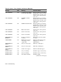
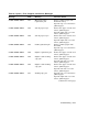
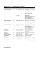
Common Operating Problems . . . . . . . .
Communication Errors . . . . . . . . . . . . . .
Error, Supplies, and Service Messages . .
LJ2D Error Messages . . . . . . . . . . . . . .
Paper Jams . . . . . . . . . . . . . . . . . . . . . .
Basic Paper Jam Clearance Procedure . .
Detailed Paper Jam Clearing Procedure
.
.
.
.
.
.
.
.
.
.
.
.
.
.
.
.
.
.
.
.
.
.
.
.
.
.
.
.
.
.
.
.
.
.
.
.
.
.
.
.
.
.
.
.
.
.
.
.
.
.
.
.
.
.
.
.
.
.
.
.
.
.
.
.
.
.
.
.
.
.
.
.
.
.
.
.
.
.
.
.
.
.
.
.
.
.
.
.
.
.
.
.
.
.
.
.
.
.
.
.
.
.
.
.
.
.
.
.
.
.
.
.
7 Maintenance
7.1
v
8 Service
8.1
Digital Equipment Corporation Services . . . . . . . . . . . . . . . . . . .
8–1
A DEC PPL3 Quick Reference Guide
A.1
A.2
A.3
A.4
A.5
A.6
A.7
A.8
A.9
Unit Selection . . . . . . . . . . . . . . . . . . . . . . . . . .
Spacing, Implicit Cursor Motion, Sheet Size and
Tabs . . . . . . . . . . . . . . . . . . . . . . . . . . . . . . . . . .
Explicit Cursor Movement . . . . . . . . . . . . . . . . .
Font Management and Attribute Selection . . . .
Vectors . . . . . . . . . . . . . . . . . . . . . . . . . . . . . . . .
Reports . . . . . . . . . . . . . . . . . . . . . . . . . . . . . . . .
Device Control . . . . . . . . . . . . . . . . . . . . . . . . . .
Miscellaneous . . . . . . . . . . . . . . . . . . . . . . . . . . .
.......
Margins
.......
.......
.......
.......
.......
.......
.......
.
.
.
.
.
.
.
.
.
.
.
.
.
.
.
.
.
.
.
.
.
.
.
.
.
.
.
.
.
.
.
.
.
.
.
.
.
.
.
.
.
.
.
.
.
.
.
.
.
.
.
.
.
.
A–3
A–3
A–10
A–11
A–13
A–20
A–21
A–25
A–27
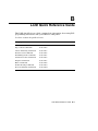
B LJ2D Quick Reference Guide
B.1
B.2
B.3
B.4
B.5
B.6
B.7
B.8
B.9
B.10
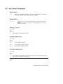
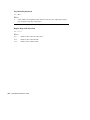
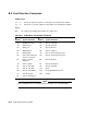
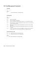
Job Control Commands . . . . . .
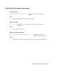
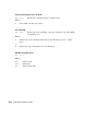
Page Control Commands . . . . .
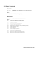
Cursor Positioning Commands .
Font Selection Commands . . . .
Font Management Commands .
Soft Font Creation Commands .
Graphics Command . . . . . . . . .
Macro Commands . . . . . . . . . .
Troubleshooting Commands . . .
Protocol Switching Commands .
.
.
.
.
.
.
.
.
.
.
.
.
.
.
.
.
.
.
.
.
.
.
.
.
.
.
.
.
.
.
.
.
.
.
.
.
.
.
.
.
.
.
.
.
.
.
.
.
.
.
.
.
.
.
.
.
.
.
.
.
.
.
.
.
.
.
.
.
.
.
.
.
.
.
.
.
.
.
.
.
.
.
.
.
.
.
.
.
.
.
.
.
.
.
.
.
.
.
.
.
.
.
.
.
.
.
.
.
.
.
.
.
.
.
.
.
.
.
.
.
.
.
.
.
.
.
.
.
.
.
.
.
.
.
.
.
.
.
.
.
.
.
.
.
.
.
.
.
.
.
.
.
.
.
.
.
.
.
.
.
.
.
.
.
.
.
.
.
.
.
.
.
.
.
.
.
.
.
.
.
.
.
.
.
.
.
.
.
.
.
.
.
.
.
.
.
.
.
.
.
.
.
.
.
.
.
.
.
.
.
.
.
.
.
.
.
.
.
.
.
.
.
.
.
.
.
.
.
.
.
.
.
.
.
.
.
.
.
.
.
.
.
.
.
.
.
.
.
.
.
.
.
.
.
.
.
.
.
.
.
B–3
B–5
B–8
B–12
B–16
B–17
B–18
B–21
B–22
B–22
Creating the Device Control Library .
Installing the Device Control Library
Modifying the Device Control Library
Using the Setup Modules . . . . . . . . . .
.
.
.
.
.
.
.
.
.
.
.
.
.
.
.
.
.
.
.
.
.
.
.
.
.
.
.
.
.
.
.
.
.
.
.
.
.
.
.
.
.
.
.
.
.
.
.
.
.
.
.
.
.
.
.
.
.
.
.
.
.
.
.
.
.
.
.
.
.
.
.
.
.
.
.
.
.
.
.
.
.
.
.
.
D–1
D–3
D–4
D–5
C PostScript Operators
D VMS Device Control Library Example
D.1
D.2
D.3
D.4
vi
E LN03 Compatibility
E.1
E.2
E.3
General Differences . . . . . . . . . . . . . . . . . . . . . . . . . . . . . . . . . . .
Printable Area Compatibility . . . . . . . . . . . . . . . . . . . . . . . . . . . .
DEC PPL3 Protocol Compatibility . . . . . . . . . . . . . . . . . . . . . . . .
E–1
E–2
E–2
F Fonts for the DEClaser 3200 Printer
F.1
F.2
F.3
F.3.1
F.3.2
F.4
F.5
F.5.1
F.5.2
Font Attributes . . . . . . . . . . . . . . . . . . . . . . . . . .
Supported Font Cartridges . . . . . . . . . . . . . . . . . .
Selecting Fonts . . . . . . . . . . . . . . . . . . . . . . . . . .
WPS–PLUS . . . . . . . . . . . . . . . . . . . . . . . . . .
DECmate/WPS . . . . . . . . . . . . . . . . . . . . . . . .
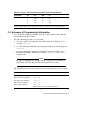
Summary of Programming Information . . . . . . . .
Using Barcode 3 of 9 . . . . . . . . . . . . . . . . . . . . . .
Encoding a Symbol . . . . . . . . . . . . . . . . . . . . .
Character Combinations for Extended Codes .
.
.
.
.
.
.
.
.
.
.
.
.
.
.
.
.
.
.
.
.
.
.
.
.
.
.
.
.
.
.
.
.
.
.
.
.
.
.
.
.
.
.
.
.
.
.
.
.
.
.
.
.
.
.
.
.
.
.
.
.
.
.
.
.
.
.
.
.
.
.
.
.
.
.
.
.
.
.
.
.
.
.
.
.
.
.
.
.
.
.
.
.
.
.
.
.
.
.
.
.
.
.
.
.
.
.
.
.
F–1
F–2
F–4
F–4
F–5
F–7
F–9
F–10
F–10
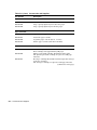
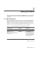
Ordering Information . . . . . . . . . . . . . . . . . . . . . . . . . . . . . . . . . .
G–5
G Accessories and Supplies
G.1
H Specifications
H.1
Operating Specifications . . . . . . .
H.2
Serial Interface Signals . . . . . . .
H.2.1
Connector . . . . . . . . . . . . . . .
H.2.1.1
Send Common . . . . . . . .
H.2.1.2
Receive Common . . . . . .
H.2.1.3
Receive Data . . . . . . . . .
H.2.1.4
Send Data . . . . . . . . . . .
H.2.1.5
Terminal Ready . . . . . . .
H.2.1.6
Data Set Ready . . . . . . .
H.3
Parallel Interface Requirements
H.3.1
Connector . . . . . . . . . . . . . . .
H.3.2
Interface Signals . . . . . . . . .
.
.
.
.
.
.
.
.
.
.
.
.
.
.
.
.
.
.
.
.
.
.
.
.
.
.
.
.
.
.
.
.
.
.
.
.
.
.
.
.
.
.
.
.
.
.
.
.
.
.
.
.
.
.
.
.
.
.
.
.
.
.
.
.
.
.
.
.
.
.
.
.
.
.
.
.
.
.
.
.
.
.
.
.
.
.
.
.
.
.
.
.
.
.
.
.
.
.
.
.
.
.
.
.
.
.
.
.
.
.
.
.
.
.
.
.
.
.
.
.
.
.
.
.
.
.
.
.
.
.
.
.
.
.
.
.
.
.
.
.
.
.
.
.
.
.
.
.
.
.
.
.
.
.
.
.
.
.
.
.
.
.
.
.
.
.
.
.
.
.
.
.
.
.
.
.
.
.
.
.
.
.
.
.
.
.
.
.
.
.
.
.
.
.
.
.
.
.
.
.
.
.
.
.
.
.
.
.
.
.
.
.
.
.
.
.
.
.
.
.
.
.
.
.
.
.
.
.
.
.
.
.
.
.
.
.
.
.
.
.
.
.
.
.
.
.
.
.
.
.
.
.
.
.
.
.
.
.
.
.
.
.
.
.
.
.
.
.
.
.
.
.
.
.
.
.
.
.
.
.
.
.
.
.
.
.
.
.
.
.
.
.
.
.
.
.
.
.
.
.
H–1
H–4
H–4
H–4
H–5
H–5
H–5
H–5
H–5
H–6
H–6
H–6
vii
I Cabling Information
I.1
I.2
I.2.1
I.2.2
Cable Combinations . . . . . . . . . . . . .
Interface Programming Instructions
Serial Flow Control . . . . . . . . . .
Parallel Communication . . . . . . .
.
.
.
.
.
.
.
.
.
.
.
.
.
.
.
.
.
.
.
.
.
.
.
.
.
.
.
.
.
.
.
.
.
.
.
.
.
.
.
.
.
.
.
.
.
.
.
.
.
.
.
.
.
.
.
.
.
.
.
.
.
.
.
.
.
.
.
.
.
.
.
.
.
.
.
.
.
.
.
.
.
.
.
.
.
.
.
.
I–1
I–4
I–4
I–5
Printer Components: Front View . . . . . . . . . . . . .
Printer Components: Rear View . . . . . . . . . . . . .
Printer Components: Inside View . . . . . . . . . . . .
Operating Space . . . . . . . . . . . . . . . . . . . . . . . . . .
Printer Status . . . . . . . . . . . . . . . . . . . . . . . . . . .
Control Panel . . . . . . . . . . . . . . . . . . . . . . . . . . . .
Operational Information . . . . . . . . . . . . . . . . . . .
Error Information . . . . . . . . . . . . . . . . . . . . . . . .
Menu Information . . . . . . . . . . . . . . . . . . . . . . . .
Feature Information . . . . . . . . . . . . . . . . . . . . . . .
Menu Information . . . . . . . . . . . . . . . . . . . . . . . .
Feature Information . . . . . . . . . . . . . . . . . . . . . . .
Operating Flow . . . . . . . . . . . . . . . . . . . . . . . . . .
Set Up Menu Block Diagram . . . . . . . . . . . . . . . .
DEC PPL3 Menu . . . . . . . . . . . . . . . . . . . . . . . . .
Duplex Input . . . . . . . . . . . . . . . . . . . . . . . . . . . .
Duplex and Simplex Output . . . . . . . . . . . . . . . . .
Duplex Master and Simplex Compressed Output .
LJ2D Menu . . . . . . . . . . . . . . . . . . . . . . . . . . . . .
PostScript Menu . . . . . . . . . . . . . . . . . . . . . . . . .
Start Page . . . . . . . . . . . . . . . . . . . . . . . . . . . . . .
Configuration Sheet . . . . . . . . . . . . . . . . . . . . . . .
Font Status Sheet . . . . . . . . . . . . . . . . . . . . . . . .
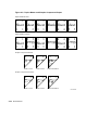
Unacceptable Envelopes . . . . . . . . . . . . . . . . . . . .
Printing Border . . . . . . . . . . . . . . . . . . . . . . . . . .
.
.
.
.
.
.
.
.
.
.
.
.
.
.
.
.
.
.
.
.
.
.
.
.
.
.
.
.
.
.
.
.
.
.
.
.
.
.
.
.
.
.
.
.
.
.
.
.
.
.
.
.
.
.
.
.
.
.
.
.
.
.
.
.
.
.
.
.
.
.
.
.
.
.
.
.
.
.
.
.
.
.
.
.
.
.
.
.
.
.
.
.
.
.
.
.
.
.
.
.
.
.
.
.
.
.
.
.
.
.
.
.
.
.
.
.
.
.
.
.
.
.
.
.
.
.
.
.
.
.
.
.
.
.
.
.
.
.
.
.
.
.
.
.
.
.
.
.
.
.
.
.
.
.
.
.
.
.
.
.
.
.
.
.
.
.
.
.
.
.
.
.
.
.
.
.
.
.
.
.
.
.
.
.
.
.
.
.
.
.
.
.
.
.
.
.
.
.
.
.
.
.
.
.
.
.
.
.
.
.
.
.
.
.
.
.
.
.
.
.
.
.
.
.
.
1–2
1–4
1–6
1–8
2–1
3–2
3–9
3–9
3–10
3–10
4–4
4–4
4–6
4–13
4–15
4–20
4–21
4–22
4–28
4–38
4–46
4–57
4–59
5–5
5–6
Glossary
Index
Figures
1–1
1–2
1–3
1–4
2–1
3–1
3–2
3–3
3–4
3–5
4–1
4–2
4–3
4–4
4–5
4–6
4–7
4–8
4–9
4–10
4–11
4–12
4–13
5–1
5–2
viii
6–1
6–2
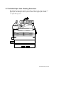
Printer Paper Paths . . . . . . . . . . . . . . . . . . . . . . . . . . . . . . . .
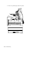
Paper Jam Locations . . . . . . . . . . . . . . . . . . . . . . . . . . . . . . .
6–20
6–21
Printer Components: Front View . . . . . . . . . . . . .
Printer Components: Rear View . . . . . . . . . . . . .
Printer Components: Inside View . . . . . . . . . . . .
Printer Status Messages . . . . . . . . . . . . . . . . . . .
PostScript Messages . . . . . . . . . . . . . . . . . . . . . . .
Single-Size Paper Cassettes . . . . . . . . . . . . . . . . .
Example of Setting the Adjustable Cassette Size .
Selecting Manual Feed Mode . . . . . . . . . . . . . . . .
Control Panel Functions . . . . . . . . . . . . . . . . . . .
Selecting a Printer Menu . . . . . . . . . . . . . . . . . . .
Key Functions: Menu Mode . . . . . . . . . . . . . . . . .
System Memory Allocation . . . . . . . . . . . . . . . . . .
Changing and Saving Menu Selections . . . . . . . .
Protocol . . . . . . . . . . . . . . . . . . . . . . . . . . . . . . . .
Tray Selection . . . . . . . . . . . . . . . . . . . . . . . . . . .
Logical and Physical Print Mode Interactions . . .
Duplex . . . . . . . . . . . . . . . . . . . . . . . . . . . . . . . . .
Memory Management Feature . . . . . . . . . . . . . . .
Auto Wrap . . . . . . . . . . . . . . . . . . . . . . . . . . . . . .
New Line . . . . . . . . . . . . . . . . . . . . . . . . . . . . . . .
User Preference Set . . . . . . . . . . . . . . . . . . . . . . .
Device ID . . . . . . . . . . . . . . . . . . . . . . . . . . . . . . .
Power-Up Message . . . . . . . . . . . . . . . . . . . . . . . .
Control Representation Mode . . . . . . . . . . . . . . . .
Copies . . . . . . . . . . . . . . . . . . . . . . . . . . . . . . . . .
Tray Selection . . . . . . . . . . . . . . . . . . . . . . . . . . .
Duplex . . . . . . . . . . . . . . . . . . . . . . . . . . . . . . . . .
Font Number . . . . . . . . . . . . . . . . . . . . . . . . . . . .
Paper Size . . . . . . . . . . . . . . . . . . . . . . . . . . . . . .
Orientation . . . . . . . . . . . . . . . . . . . . . . . . . . . . .
Form Length . . . . . . . . . . . . . . . . . . . . . . . . . . . .
Page Buffer Feature . . . . . . . . . . . . . . . . . . . . . . .
1–3
1–5
1–7
2–2
2–3
2–7
2–16
2–19
3–2
4–2
4–3
4–9
4–10
4–14
4–16
4–17
4–19
4–23
4–24
4–24
4–25
4–26
4–26
4–27
4–29
4–30
4–31
4–31
4–32
4–32
4–33
4–34
Tables
1–1
1–2
1–3
2–1
2–2
2–3
2–4
2–5
3–1
4–1
4–2
4–3
4–4
4–5
4–6
4–7
4–8
4–9
4–10
4–11
4–12
4–13
4–14
4–15
4–16
4–17
4–18
4–19
4–20
4–21
4–22
4–23
.
.
.
.
.
.
.
.
.
.
.
.
.
.
.
.
.
.
.
.
.
.
.
.
.
.
.
.
.
.
.
.
.
.
.
.
.
.
.
.
.
.
.
.
.
.
.
.
.
.
.
.
.
.
.
.
.
.
.
.
.
.
.
.
.
.
.
.
.
.
.
.
.
.
.
.
.
.
.
.
.
.
.
.
.
.
.
.
.
.
.
.
.
.
.
.
.
.
.
.
.
.
.
.
.
.
.
.
.
.
.
.
.
.
.
.
.
.
.
.
.
.
.
.
.
.
.
.
.
.
.
.
.
.
.
.
.
.
.
.
.
.
.
.
.
.
.
.
.
.
.
.
.
.
.
.
.
.
.
.
.
.
.
.
.
.
.
.
.
.
.
.
.
.
.
.
.
.
.
.
.
.
.
.
.
.
.
.
.
.
.
.
.
.
.
.
.
.
.
.
.
.
.
.
.
.
.
.
.
.
.
.
.
.
.
.
.
.
.
.
.
.
.
.
.
.
.
.
.
.
.
.
.
.
.
.
.
.
.
.
.
.
.
.
.
.
.
.
.
.
.
.
.
.
.
.
.
.
.
.
.
.
.
.
.
.
.
.
.
.
.
.
.
.
.
.
.
.
.
.
.
.
.
.
.
.
.
.
ix
4–24
4–25
4–26
4–27
4–28
4–29
4–30
4–31
4–32
4–33
4–34
4–35
4–36
4–37
4–38
4–39
4–40
4–41
4–42
4–43
4–44
4–45
4–46
4–47
4–48
5–1
5–2
5–3
5–4
6–1
6–2
6–3
8–1
A–1
A–2
B–1
B–2
x
Symbol Set . . . . . . . . . . . . . . . . . . . . . .
PostScript Memory Allocation . . . . . . .
Duplex . . . . . . . . . . . . . . . . . . . . . . . . .
Tumble . . . . . . . . . . . . . . . . . . . . . . . . .
Paper Tray . . . . . . . . . . . . . . . . . . . . . .
Tray Switching . . . . . . . . . . . . . . . . . . .
Tray Switch Sequence . . . . . . . . . . . . .
Manual/Multi-Media Paper Sizes . . . . .
Output Offset . . . . . . . . . . . . . . . . . . . .
Wait Timeout . . . . . . . . . . . . . . . . . . . .
Start Page . . . . . . . . . . . . . . . . . . . . . .
Jam Recovery . . . . . . . . . . . . . . . . . . . .
Allow Job Reset . . . . . . . . . . . . . . . . . .
Aborting a Print Job . . . . . . . . . . . . . .
Asynchronous Control Mode . . . . . . . . .
Adjustable Paper Cassette Sizes . . . . .
Alarm Feature . . . . . . . . . . . . . . . . . . .
Communications Interface . . . . . . . . . .
Baud Rate . . . . . . . . . . . . . . . . . . . . . .
Parity . . . . . . . . . . . . . . . . . . . . . . . . . .
Flow Control . . . . . . . . . . . . . . . . . . . .
Language . . . . . . . . . . . . . . . . . . . . . . .
Communications Error . . . . . . . . . . . . .
Test Menu . . . . . . . . . . . . . . . . . . . . . .
Defaults Menu . . . . . . . . . . . . . . . . . . .
Paper Specifications . . . . . . . . . . . . . . .
Transparency Sizes . . . . . . . . . . . . . . .
Transparency Specifications . . . . . . . . .
Self-Adhesive Label Specifications . . . .
Common Operating Problems . . . . . . .
Error, Supplies, and Service Messages .
LJ2D Error Messages . . . . . . . . . . . . .
Questions to Consider Before You Call .
DECVPFS Numeric Parameters1 . . . . .
Character Set Identification . . . . . . . . .
ID Numbers and Symbol Set Names . .
Stroke Weight Examples . . . . . . . . . . .
.
.
.
.
.
.
.
.
.
.
.
.
.
.
.
.
.
.
.
.
.
.
.
.
.
.
.
.
.
.
.
.
.
.
.
.
.
.
.
.
.
.
.
.
.
.
.
.
.
.
.
.
.
.
.
.
.
.
.
.
.
.
.
.
.
.
.
.
.
.
.
.
.
.
.
.
.
.
.
.
.
.
.
.
.
.
.
.
.
.
.
.
.
.
.
.
.
.
.
.
.
.
.
.
.
.
.
.
.
.
.
.
.
.
.
.
.
.
.
.
.
.
.
.
.
.
.
.
.
.
.
.
.
.
.
.
.
.
.
.
.
.
.
.
.
.
.
.
.
.
.
.
.
.
.
.
.
.
.
.
.
.
.
.
.
.
.
.
.
.
.
.
.
.
.
.
.
.
.
.
.
.
.
.
.
.
.
.
.
.
.
.
.
.
.
.
.
.
.
.
.
.
.
.
.
.
.
.
.
.
.
.
.
.
.
.
.
.
.
.
.
.
.
.
.
.
.
.
.
.
.
.
.
.
.
.
.
.
.
.
.
.
.
.
.
.
.
.
.
.
.
.
.
.
.
.
.
.
.
.
.
.
.
.
.
.
.
.
.
.
.
.
.
.
.
.
.
.
.
.
.
.
.
.
.
.
.
.
.
.
.
.
.
.
.
.
.
.
.
.
.
.
.
.
.
.
.
.
.
.
.
.
.
.
.
.
.
.
.
.
.
.
.
.
.
.
.
.
.
.
.
.
.
.
.
.
.
.
.
.
.
.
.
.
.
.
.
.
.
.
.
.
.
.
.
.
.
.
.
.
.
.
.
.
.
.
.
.
.
.
.
.
.
.
.
.
.
.
.
.
.
.
.
.
.
.
.
.
.
.
.
.
.
.
.
.
.
.
.
.
.
.
.
.
.
.
.
.
.
.
.
.
.
.
.
.
.
.
.
.
.
.
.
.
.
.
.
.
.
.
.
.
.
.
.
.
.
.
.
.
.
.
.
.
.
.
.
.
.
.
.
.
.
.
.
.
.
.
.
.
.
.
.
.
.
.
.
.
.
.
.
.
.
.
.
.
.
.
.
.
.
.
.
.
.
.
.
.
.
.
.
.
.
.
.
.
.
.
.
.
.
.
.
.
.
.
.
.
.
.
.
.
.
.
.
.
.
.
.
.
.
.
.
.
.
.
.
.
.
.
.
.
.
.
.
.
.
.
.
.
.
.
.
.
.
.
.
.
.
.
.
.
.
.
.
.
.
.
.
.
.
.
.
.
.
.
.
.
.
.
.
.
.
.
.
.
.
.
.
.
.
.
.
.
.
.
.
.
.
.
.
.
.
.
.
.
.
.
.
.
.
.
.
.
.
.
.
.
.
.
.
.
.
.
.
.
.
.
.
.
.
.
.
.
.
.
.
.
.
4–35
4–37
4–39
4–39
4–40
4–41
4–42
4–43
4–44
4–44
4–45
4–47
4–48
4–48
4–49
4–50
4–50
4–51
4–52
4–53
4–54
4–55
4–55
4–56
4–60
5–2
5–7
5–7
5–8
6–2
6–9
6–18
8–2
A–5
A–17
B–12
B–14
C–1
D–1
D–2
F–1
F–2
F–3
G–1
G–2
G–3
H–1
H–2
H–3
I–1
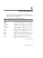
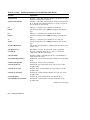
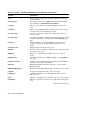
PostScript Operators on the DEClaser 3200 Printer . . . . . .
Filenames and Contents for Example SETUP Modules . . . .
ANSI_SETUPS Example Device Control Library Reference
Guide . . . . . . . . . . . . . . . . . . . . . . . . . . . . . . . . . . . . . . . . . .
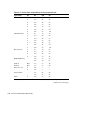
Font Cartridge Characteristics . . . . . . . . . . . . . . . . . . . . . . .
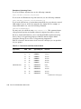
Printer Font Control Block for Proportional Fonts . . . . . . . .
Font Access and Font Control Values . . . . . . . . . . . . . . . . . .
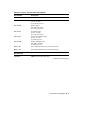
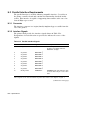
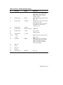
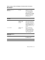
Accessories and Supplies . . . . . . . . . . . . . . . . . . . . . . . . . . .
Ordering Within the U.S.A. . . . . . . . . . . . . . . . . . . . . . . . . .
Ordering Outside the U.S.A. . . . . . . . . . . . . . . . . . . . . . . . .
DEClaser 3200 Specifications . . . . . . . . . . . . . . . . . . . . . . . .
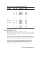
Serial Interface Signals . . . . . . . . . . . . . . . . . . . . . . . . . . . .
Parallel Interface Signals . . . . . . . . . . . . . . . . . . . . . . . . . . .
Cables and Adapters for Communication Connections . . . . .
.
.
C–1
D–2
.
.
.
.
.
.
.
.
.
.
.
D–7
F–3
F–6
F–8
G–1
G–5
G–5
H–1
H–4
H–6
I–1
xi
Preface
The DEClaser 3200 printer uses electrophotographic laser technology to print
text and graphics. It has a print resolution of 300 x 300 dots per inch and
prints at speeds up to 13 pages per minute in simplex mode, and 11 pages per
minute in duplex mode. The printer consists of an engine (print mechanism)
and a controller (formatter) that are driven from host-based software to provide
shared printer access from the Digital network. The printer can serve as a
personal desktop printer or as a shared group printer.
The following are some of the features of the DEClaser 3200 printer:
•
Two input paper trays, each with a capacity of up to 250 sheets of standard
80 g/m2 (20 lb.) paper
•
An output tray capacity of up to 500 sheets with accurate stacking and job
offset
•
Ability to print on paper, transparencies, labels, envelopes, and letterhead
stationery
•
Manual feed capacity for envelopes, labels, transparencies, or paper
•
Support for both serial and parallel communication interfaces
•
Convenient, easy-to-perform user maintenance
•
Control panel with a liquid crystal display (LCD) that shows printer status
at a glance
•
Power saving mode that is invoked after the printer is idle for 2 hours
•
Capacity for two optional font cartridges
•
Built-in HP LaserJet IID protocol emulation
xiii
Options
In addition to the standard features, the following options are available for the
DEClaser 3200 printer:
•
A Legal-size paper cassette (8.5 in. x 14 in.)
•
An adjustable paper cassette designed to accept various paper sizes
(accommodates widths from 182 mm to 216 mm (7.17 in. to 8.5 in.) and
lengths from 254 mm to 356 mm (10 in. to 14 in.))
•
An A4 or Letter-size large capacity input tray (holds up to 1500 sheets of
80 g/m2 (20 lb.) paper)
•
A multi-media feeder designed to feed envelopes, transparencies, and
self-adhesive labels (also feeds up to 200 sheets of 80 g/m2 (20 lb.) paper)
•
User-installable memory upgrade (up to 10.5 MB)
•
Various Digital ANSI-compliant font cartridges
•
HP LaserJet IID-compatible emulation font cartridges
•
A user-installable PostScript emulation upgrade compatible with Adobe’s
PostScript page description language, gives the DEClaser 3200 printer the
ability to print PostScript files.
See Appendix G for ordering information about these options.
xiv
Software Requirements
The availability of some features of the DEClaser 3200 printer depends on the
operating and applications software used by the host computer system. For
example, the DEClaser 3200 printer has the ability to print bold characters,
but if your application program does not support bold printing, this feature
would not be available. For information about the printer features you
can use with your application program, consult your application program
documentation.
For help choosing the right software package for your application needs,
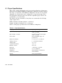
contact your Digital sales representative.
Document Structure
This guide explains how to use and maintain the DEClaser 3200 printer. It
primarily covers the hardware (physical) aspects of the printer. For printer
installation instructions, refer to the DEClaser 3200 Printer Installation
Guide in this binder. See the Associated Documents section in this preface for
information about software manuals that pertain to the DEClaser 3200 printer.
xv
The guide is organized as follows:
xvi
•
Chapter 1, Printer Components, describes the components and functions of
the DEClaser 3200 printer.
•
Chapter 2, Printer Operation, covers operating procedures such as
powering the printer on and off and loading the paper cassettes. It also
describes the printer status messages that are displayed during printer
operation.
•
Chapter 3, The Control Panel, covers the use of the printer’s control
panel. It describes operational information about the indicators, keys, and
message display.
•
Chapter 4, Printer Menus, explains how to configure the printer so that
it can communicate with your computer system (Set Up Menu), how to
save current settings or recall factory defaults (Defaults Menu), how to
print the configuration sheet and font listings, and how to enter the control
representation mode of operation (Test Menu).
•
Chapter 5, Print Media, describes the various printing media that can
be used, including paper, envelopes, transparencies, and labels. It also
addresses the proper way to store and handle paper.
•
Chapter 6, Troubleshooting, contains basic testing and troubleshooting
techniques that allow you to correct common operating problems, such as
poor printing and paper jams.
•
Chapter 7, Maintenance, explains how to care for and maintain the printer.
•
Chapter 8, Service, explains how to obtain service if the printer needs
repair.
•
Appendix A, DEC PPL3 Quick Reference Guide, lists the commands used
to program the printer when DEC PPL3 protocol is selected. It is intended
as a reference for the experienced programmer.
•
Appendix B, LJ2D Quick Reference Guide, lists the commands used to
program the printer when the LJ2D emulation mode is selected. It is
intended as a reference for the experienced programmer.
•
Appendix C, PostScript Operators Quick Reference Guide, lists the
PostScript operators for the DEClaser 3200 printer. It is intended as a
reference for the experienced programmer.
•
Appendix D, VMS Device Control Library Example, contains an example
procedure for creating and installing a device control library with useful
printer features for the VMS operating system.
•
Appendix E, LN03 Compatibility, highlights some of the differences
between the DEClaser 3200 printer and the LN03 family of printers.
•
Appendix F, Font Cartridge Information, contains information on how to
access and use fonts from optional Digital ANSI-compliant font cartridges.
•
Appendix G, Accessories and Supplies, lists some of the accessories and
supplies available for the DEClaser 3200 printer and explains how to order
them.
•
Appendix H, Specifications, lists the power, environmental, and physical
specifications of the printer.
•
Appendix I, Cabling Information, lists the interface cables available for
various host devices. This appendix also describes interface programming
instructions for the IBM PC.
•
The glossary contains definitions of printer-related terms.
Ordering Additional Copies of This Documentation Set
You can order additional copies of this documentation set from Digital as
described in Appendix G. The ordering number for the documentation kit is
EK–D3200–DK.
The documentation kit consists of the following:
•
DEClaser 3200 Printer Installation Guide
•
DEClaser 3200 Printer Operator’s Guide
•
DEClaser 3200 Printer Operator’s Quick Reference Guide
•
Spine insert for the binder
•
Three-ring binder
NOTE
You cannot order the installation or the operator’s guide individually.
They only can be ordered as part of the complete documentation kit.
The operator’s quick reference guide can be ordered separately (see
Appendix G.)
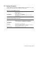
xvii
Associated Documents
Other manuals are available for use with the DEClaser 3200 printer. You can
order these optional manuals from Digital as described in Appendix G.
•
Digital ANSI-Compliant Printing Protocol Level 3 Programming Reference
Manual (AA–PBWGA–TE)
This manual is for application programmers who create software that
produces Digital ANSI-Compliant Printing Protocol level 3 output.
It describes printer protocol character processing and printer control
functions.
•
Digital ANSI-Compliant Printing Protocol Level 3 Programming
Supplement (EK–PPLV3–PS)
This manual contains information specific to the DEClaser 3200 printer for
programmers who create applications for Digital’s ANSI-compliant level
3 devices. It is also for programmers who write applications with ANSI
output that require conversion to the PostScript page description language
for printing on Digital printers.
•
PostScript Printing Programming Supplement (EK–POSTP–PS)
This manual contains information specific to the DEClaser 3200 printer for
programmers who create applications using the PostScript page description
language.
•
PostScript Tutorial/Reference Manuals Kit (QA–VVZAD–GZ)
This PostScript tutorial/reference manuals kit contain’s the following
manuals:
•
xviii
•
PostScript Language Reference Manual
•
PostScript Language Tutorial and Cookbook
PostScript Translators Reference Manual for ReGIS and Tektronix
4010/4014 (AA–PBWFA–TE)
This manual is for programmers who need to convert ReGIS or Tektronix
4010/4014 documents to PostScript for printing on PostScript printers.
In addition to PostScript (when the PostScript option is installed), the
DEClaser 3200 printer can also print Tektronix 4010/4014 and ReGIS files
using DECprint Printing Services.
Conventions Used in This Guide
The following terms and conventions are used in this guide:
Convention
Meaning
NOTE
Notes provide important additional information.
CAUTION
Cautions provide information required to prevent
damage to equipment.
WARNING
Warnings provide information to prevent personal
injury.
Dash (–)
A statement preceded by a dash describes the result
of a procedural step. For example:
1. Insert the paper cassette into the printer.
The Error indicator shuts off.
Check Mark ( )
A statement preceded by a check mark indicates a
special instruction related to a procedural step. For
example:
1. Insert the paper into the cassette, making sure
the stack is below the paper snubbers.
To prevent paper jams, do not load paper above
the MAX limit line.
Key
A key name is shown enclosed in a box to indicate
that you press that key on the control panel. Key
names are always shown in initial capital letters.
For example:
1. Press
UPPERCASE
Test to enter the Test Menu.
All information on the message display is shown in
uppercase. For example:
Printer status reads READY.
xix
Safety Information
The DEClaser 3200 printer complies with all United States government
safety regulations applicable to laser beam light exposure. Read the following
information to become familiar with laser safety.
Laser Safety
The DEClaser 3200 printer complies with 21 CFR Chapter 1, Subchapter J,
as a Class 1 laser product under the U.S. Department of Health and Human
Services (DHHS) Radiation Performance Standard according to the Radiation
Control for Health and Safety Act of 1968. The printer does not emit hazardous
light, since the laser beam is totally enclosed during all modes of customer
operation and maintenance.
WARNING
Use of controls or adjustment procedures other than those specified in
this manual may result in hazardous laser light exposure.
CDRH Regulations
The Center for Devices and Radiological Health (CDRH) of the U.S. Food and
Drug Administration implemented regulations for laser products on August
2, 1976. These regulations apply to laser products manufactured beginning
August 1, 1976. Compliance is mandatory for products marketed in the United
States.
xx
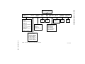
1
Printer Components
This chapter describes the components of the DEClaser 3200 printer and their
functions. This chapter also provides information about the operating space
required to perform day-to-day printing operations.
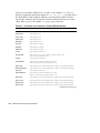
1.1 Printer Components and Functions
This section points out the various printer components of the DEClaser
3200 printer. You should become familiar with the names and locations
of the components because they are referred to on the message display
and throughout the rest of this manual. Figure 1–1 and Figure 1–2 show the
location of the external components such as release levers and cable connectors.
These items are described in Table 1–1 and Table 1–2.
Figure 1–3 shows internal components such as the toner cartridge and
photoreceptor drum. All of the items called out in Figure 1–3 (except for the
print density adjustment knob) are consumables which are replaced at regular
intervals. Table 1–3 descibes the function of these components.
Printer Components 1–1
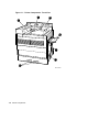
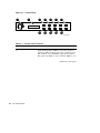
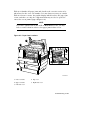
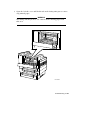
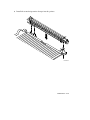
Figure 1–1 Printer Components: Front View
1
2
7
3
4
5
6
MLO-006248
1–2 Printer Components
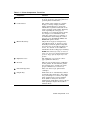
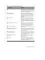
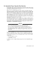
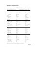
Table 1–1 Printer Components: Front View
Component
Function
1
Top Cover Release Lever
Lifting this lever unlocks the top cover so
it can be opened to clear paper jams or to
perform printer maintenance.
2
Control Panel
The control panel consists of a graphic
display, a message display, indicator
lights, and function keys. It provides
information on printer status and can be
used to perform certain printer functions,
such as printing the last page of a
document or accessing the printer menus.
See Chapter 3 for information about
using the control panel. See Chapter 4
for information about using the control
panel to access the SET UP, TEST, and
DEFAULTS printer menus.
3
Manual Feed Tray
Single sheets of paper, transparencies,
self-adhesive labels, or envelopes can be
manually fed into the printer using this
tray. The tray can be folded in when not
in use. See Section 2.7 for additional
information about feeding paper manually.
NOTE: The manual feed tray is removed
when you connect an optional multi-media
feeder or large capacity input tray to the
printer.
4
Right-Side Cover
The right-side cover opens to remove
paper jammed in this area.
5
Air Vent
This air vent provides proper ventilation
for the printer. Be sure that the printer
has adequate space around it to ensure
proper ventilation (see Section 1.2).
6
Font Cartridge Slots
These two slots accept optional font
cartridges.
7
Output Tray
Printed sheets are automatically collated
and stacked (facedown) here. The output
tray can hold up to 500 sheets of 80 g/m2
basis weight (20 lb.) paper in simplex
mode (with no offset), 400 sheets in
simplex mode (with offset), and 300 sheets
when printing in duplex mode (with or
without offset).
Printer Components 1–3
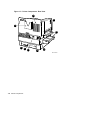
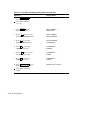
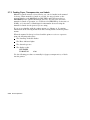
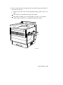
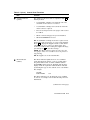
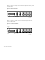
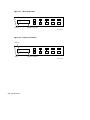
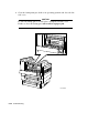
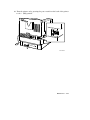
Figure 1–2 Printer Components: Rear View
9
1
8
2
7
6
5
3
4
MLO-006249
1–4 Printer Components
Table 1–2 Printer Components: Rear View
Component
Function
1
Left-Side Cover
The left-side cover opens to remove paper
jammed in this area, and to perform user
maintenance (fuser wick replacement).
Paper reverses direction in this area when
the printer is in duplex mode.
2
Upper and Lower
Paper Cassettes
The paper cassettes automatically feed
paper to the printer. Each cassette can
hold up to 250 sheets of 80 g/m2 basis
weight (20 lb.) paper. See Section 2.5 for
information about loading the cassettes
with paper.
3
Power Switch
Powers the printer on or off. Pressing
the switch to | turns power on; pressing
the switch to O turns power off. See
Section 2.3 and Section 2.4 for additional
information about powering the printer on
and off.
4
Memory Board Access Cover
This cover can be removed to install the
optional memory boards. Refer to the
instructions that come with the memory
boards for the installation procedure.
5
Power Cord Receptacle
This is where the power cord is connected
to the printer.
6
DECconnect Serial (RS423)
Interface Connector
This connector is used when the interface
cable from the host computer is a serial
cable. Refer to Appendix I for additional
cabling information.
7
Parallel (Centronics)
Interface Connector
This connector is used when the interface
cable from the host computer is a parallel
cable. Refer to Appendix I for additional
cabling information.
8
Quick Reference Guide
Holder
This is storage area used to keep the
DEClaser 3200 Quick Reference Guide
with the printer.
9
Air Vent
The cooling fan exhausts air through
this vent. Be sure that the printer has
adequate space around it to ensure proper
ventilation (see Section 1.2).
Printer Components 1–5
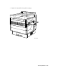
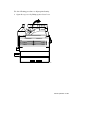
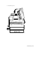
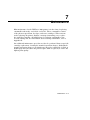
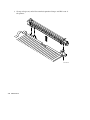
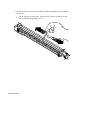
Figure 1–3 Printer Components: Inside View
2
1
3
4
5
MLO-006460
1–6 Printer Components
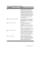
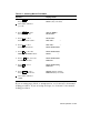
Table 1–3 Printer Components: Inside View
Component
Function
1
Transfer/Separation Charger
The transfer/separation charger places
a high positive charge on the paper
which attracts the toner image from
the photoreceptor drum onto the paper
as it passes by. You replace the charger
periodically (at the same time as the
developer cartridge) using the replacement
instructions included in the kit. Between
replacements, you may find it necessary
to clean the corotron wire and saw-tooth
comb on the charger to correct a print
quality problem. See Section 7.1 for
cleaning information.
2
Print Density Adjustment Knob
Rotating the knob clockwise darkens the
print; rotating the knob counterclockwise
lightens the print. See Section 2.8 for
additional information about setting the
print density.
3
Photoreceptor Drum (A)
Has a light-sensitive surface used to
produce the latent print image.
CAUTION: The drum should not be
exposed to ambient light for more than 10
minutes, otherwise print degradation may
occur.
You replace the photoreceptor drum at
20K page intervals, using the replacement
instructions included in the kit.
4
Developer Cartridge (C)
The developer cartridge houses the toner
cartridge. Its function is to transfer the
toner onto the photoreceptor drum and
develop the latent image on the drum.
You replace the developer cartridge at
50K page intervals, using the replacement
instructions included in the kit.
5
Toner Cartridge (B)
The toner cartridge is inserted into
the developer cartridge and is specially
formulated for the DEClaser 3200 printer.
The toner cartridge lasts approximately
6K pages, and is replaced using the
instructions included in the kit.
Printer Components 1–7
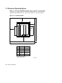
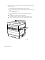
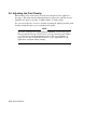
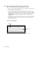
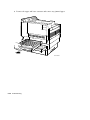
1.2 Required Operating Space
Figure 1–4 shows the minimum amount of space required to perform daily
operations. See Appendix H for additional information on environmental
conditions that must be met in order for the printer to operate properly.
Figure 1–4 Operating Space
B
C
A
Option:
MMF
or
LCIT
F
D
E
A
19.3 in
49.0 cm
B
7.5 in
19.0 cm
C
30.3 in
76.9 cm
D
24.4 in
61.9 cm
E*
67.6 in
171.7 cm
F*
51.6 in
131.1 cm
*These are the minimum
operation dimensions.
MLO-006466
1–8 Printer Components
2
Printer Operation
This chapter provides the information necessary to perform day-to-day printer
operations. It covers typical tasks, such as interpreting the printer status
messages, powering the printer on and off, adding paper, and manual feed
operation.
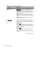
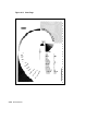
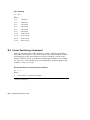
2.1 Printer Status Messages
During normal printing operations the printer status is shown in the upper left
corner of the message display (Figure 2–1). These status messages let you see
the current state of the printer at a glance.
Figure 2–1 Printer Status
Status Message
Set Up
READY
TRAY 1
DEC
SIMPLEX
Last Page
Supplies
Test
Error
Online
Defaults
Online/Pause
*
Message Display
MLO-006999
Printer Operation 2–1
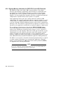
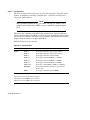
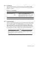
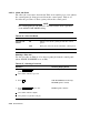
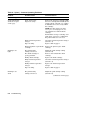
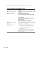
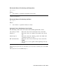
The printer status messages are shown and described in Table 2–1.
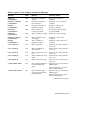
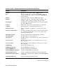
Table 2–1 Printer Status Messages
Status Message
Meaning
READY
The printer is online, ready to receive and
print data.
PAUSED
The printer is paused and not able to print
data. Data can still be received until the
printer communications buffer is full. To exit
the paused state and place the printer back on
line, press Online/Pause .
BUSY
The printer is receiving, processing, or printing
data. If Online/Pause is pressed while the
BUSY message is displayed, the Online
indicator flashes until the printer is finished
printing the current job. The printer enters
the paused state when the job is completed.
LAST PAGE1
The LAST PAGE message is displayed when
the last page of data is still in the print buffer.
To print the last page, press > .
WAITING2
Displayed when the PostScript print job
context is active, but there is no data to
process.
PLEASE WAIT
This message is displayed during either of the
following conditions:
•
The printer is warming up.
•
After clearing a printer error condition (for
example, replacing the toner cartridge),
this message is displayed briefly while the
printer is reinitializing to its state before
the error occurrence.
1
This message is displayed only when DEC PPL3 or LJ2D protocol is selected.
2
This message is displayed only when the PostScript protocol is selected.
(continued on next page)
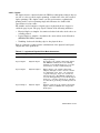
2–2 Printer Operation
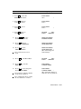
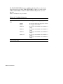
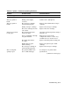
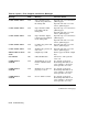
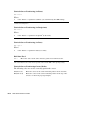
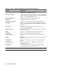
Table 2–1 (Cont.) Printer Status Messages
Status Message
Meaning
POWER SAVER ON
This message is displayed after the printer has
been idle for 2 hours. The fusing unit heater
is turned off when the printer is in the power
saver state.
The printer automatically exits the power
saver mode under either of the following
conditions:
•
The printer receives a print job from
the host or from the control panel (for
example, printing the configuration sheet).
•
Any printer cover is opened and then
closed.
•
When you switch protocols.
INITIALIZING
PS2
You select the PostScript protocol but the
printer is not ready to accept data from the
host.
TEST PRINT
PS2
Displayed when the PostScript start up page is
being composed (about 45 seconds).
2
This message is displayed only when the PostScript protocol is selected.
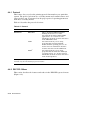
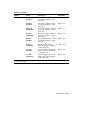
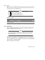
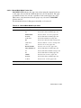
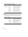
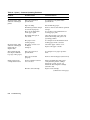
2.2 PostScript Instructional Messages
The messages shown and described in Table 2–2 are similar to the printer
status messages, but are PostScript-specific. These messages are displayed
only if the PostScript option is installed.
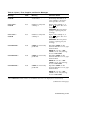
Table 2–2 PostScript Messages
Message
Meaning
WAIT FOR PAUSED
The control panel function requested cannot be
performed because a PostScript job is currently
being processed (when PostScript operator
allowjobreset is true).
PRESS
Press
to abort the current print job (when
PostScript operator allowjobreset is false).
TO ABORT
Printer Operation 2–3
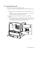
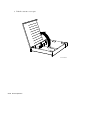
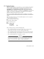
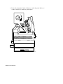
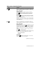
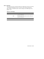
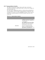
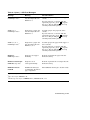
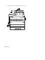
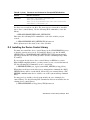
2.3 Turning the Printer On
Turn the printer on using the following procedure.
1. Press the power switch on the back of the printer to the | (ON) position.
MLO-006273
You should observe the following when you turn the printer on:
All control panel indicators light for a moment.
The Online indicator flashes while the printer is warming up, and
performs a power-on diagnostic test. Diagnostic code numbers shown
on the display change as the test is performed.
The printer status reads READY and the Online indicator remains on
following a successful completion of the diagnostic test.
If the printer does not turn on correctly, refer to Chapter 6 for
troubleshooting information.
2–4 Printer Operation
2.4 Turning the Printer Off
Turn the printer off using the following procedure.
1. Be sure the printer is not printing and that the Last Page indicator is not
on.
Turning the printer off during printing causes paper jams and loss of
data.
Turning the printer off while the Last Page indicator is on causes the
last page of data in the print buffer to be lost.
2. Press the power switch on the back of the printer to the O (OFF)
position.
After turning the printer off, always wait at least 5 seconds before you
turn the printer back on. This waiting period ensures that the printer
will initialize properly when power is turned back on.
MLO-006265
Printer Operation 2–5
2.5 Guidelines for Loading Paper
The DEClaser 3200 printer comes standard with either two A4-size
(210 mm x 297 mm) or two Letter-size (8.5 in. x 11 in.) paper cassettes,
depending on the model ordered. Each paper cassette can hold up to 250
sheets of 80 g/m2 basis weight (20 lb.) paper.
Here are some general guidelines to follow about the paper used in the printer.
•
Use only high-quality paper as specified in Chapter 5.
•
Do not use any paper that is creased, folded, clipped, stapled, or damaged.
CAUTION
Paper that is clipped or stapled can damage the printer.
•
To prevent paper curl (a curve in the paper), stack the paper on a flat
surface for storage.
•
Prevent changes to the moisture content of the paper by storing it properly
and rewrapping unused portions. Do not store paper directly on the floor.
Complete specifications for print media are in Chapter 5.
2–6 Printer Operation
2.5.1 Loading Single-Size Paper Cassettes
Each paper cassette can hold up to 250 sheets of 80 g/m2 basis weight (20 lb.)
paper. Be sure to use high-quality paper such as those listed in Appendix G, to
limit paper jams and ensure good print quality.
Do not attempt to alter the cassette to accommodate a different paper size,
as this will cause paper jams. For information about the paper sizes that the
optional adjustable paper cassette can accommodate, see Section 4.4.6.
NOTE
If you are changing paper sizes and you are using DEC PPL3 or
PostScript protocols, you must power off the printer, install the new
size cassette, and then power the printer back on again. If you are
using LJ2D protocol, you must select the paper size from the LJ2D
menu (Section 4.4.3.5.)
Single-size cassettes come in the following paper sizes.
Table 2–3 Single-Size Paper Cassettes
Paper Size
Dimensions
A4
210 mm x 297 mm
Letter
8.5 in. x 11 in.
Legal
8.5 in. x 14 in.
Printer Operation 2–7
Adding Paper to the Cassette
This section describes how to add paper to the cassettes.
NOTE
If you are changing to a new cassette size, you must perform a printer
reset after inserting the new cassette. See Section 4.6 for information
about the printer reset feature.
1. Make sure the printer has stopped printing, or that the printer status
reads PAUSED, before removing the paper cassette.
If the paper cassette has run out of paper, the Error indicator lights
and the message display reads ADD PAPER TO TRAY 1 (or 2).
CAUTION
The upper cassette can be removed (while the printer is printing)
only if printing from the lower cassette (or from an optional feeder)
in simplex mode. Do not remove the upper cassette if the printer is
printing in duplex mode.
The lower cassette can be removed and reloaded with paper while the
printer is printing from any other feed tray. Be sure to install the same
size cassette back into the printer.
2–8 Printer Operation
2. Remove the cassette from the printer by lifting it up slightly and then
pulling it straight out from the printer.
The Supplies indicator lights.
26.5%
MLO-006464
Printer Operation 2–9
3. Lift the cassette cover open.
GSF_000094_21_DG
MLO-006268
2–10 Printer Operation
4. Press down the lifting plate to lock it in the loading (lowered) position.
GSF_000094_22_DG
MLO-006269
Printer Operation 2–11
5. Tap a stack of paper on a flat surface to align the edges.
MLO-006270
2–12 Printer Operation
6. Insert the paper into the cassette, making sure the stack is below the paper
snubbers.
To prevent paper jams, do not load paper above the MAX limit line.
Load prepunched paper with the holes facing the front of the printer.
For simplex printing: load forms and letterhead paper facedown, with
the top edge inserted first.
For duplex printing: load forms and letterhead paper faceup, with the
bottom edge inserted first.
Paper Snubber
26.5%
MLO-006271
Printer Operation 2–13
7. Close the paper cassette cover and insert the cassette into the printer.
The Error indicator goes off (if it was on).
The Supplies indicator goes off.
26.5%
MLO-006272
2–14 Printer Operation
2.6 Adjustable Paper Cassette Size Selection
An adjustable paper cassette is designed to accept various paper sizes. It can
accommodate widths from 182 mm to 216 mm (7.17 in. to 8.5 in.), and lengths
from 254 mm to 356 mm (10 in. to 14 in.).
When you use a standard single-size paper cassette, the printer knows the
paper size because the cassettes are keyed to the paper size they contain. The
(optional) adjustable paper cassette however, is not keyed to a particular size
because it can accommodate multiple paper sizes. Before using an adjustable
paper cassette, you must indicate the paper size from software or through the
ADJ CASSETTE feature in the Set Up menu (see Section 4.4.6). The paper
size selected under this feature determines the printable area on the page and
should match the paper size you are using.
The DEClaser 3200 printer can be configured to recognize two different sizes
of the adjustable paper cassettes, depending on the position of the magnets on
the side of the cassette. Refer to the DEClaser 3200 Printer Adjustable Paper
Cassette User’s Guide for information about setting up the cassette for the
CASSETTE A or CASSETTE B designation.
CAUTION
If you are printing in duplex mode, it is recommended that you use the
lower cassette slot (Tray 2) to prevent possible paper jams.
If you are using two adjustable paper cassettes in duplex mode, be
sure the paper size in Tray 1 is wider than the paper size in Tray 2 (or
the LCIT if installed). Also, running out of paper in Tray 1 may cause
paper jams.
The ADJ CASSETTE feature in the Set Up menu identifies the paper size
you have loaded in the cassette. Table 2–4 is an example that describes how
to select the Legal paper size for an adjustable paper cassette. This example
assumes that:
•
Factory defaults are in use
•
CASSETTE A selected
See Table 4–39 for a complete listing of paper sizes for the adjustable paper
cassette.
Printer Operation 2–15
Table 2–4 Example of Setting the Adjustable Cassette Size
Operation
Display Reads
1. Press Online/Pause to pause
the printer.
PAUSED (printer status)
The Online indicator
goes off.
2. Press Set Up to enter
the SET UP menu.
SET UP MENU
PROTOCOL
until you reach
3. Press
the ADJ CASSETTE feature.
SET UP MENU
ADJ CASSETTE
to enter the
4. Press
ADJ CASSETTE feature.
ADJ CASSETTE
CASSETTE A
to select the
5. Press
CASSETTE A value.
CASSETTE A
LETTER
6. Press
until you reach
the LEGAL paper size.
CASSETTE A
LEGAL
to select the
7. Press
LEGAL paper size.
CASSETTE A
LEGAL
8. Press Online/Pause to place
the printer back on line.
READY (printer status)
The Online indicator
lights.
2–16 Printer Operation
*
*
*
2.7 Manual Feed Operation
The printer has a manual feed tray that can accept paper, transparencies,
labels, and envelopes. This section describes how to use the manual feed tray.
NOTE
The manual feed tray is not available if the multi-media feeder is
installed.
The manual feed tray can accommodate various media sizes from 105 mm ~
257 mm (4.13 in. ~ 10.12 in.) wide, and from 191 mm ~ 364 mm (7.5 in. ~
14.33 in.) long. Included in this range are the following popular paper and
envelope sizes:
•
Legal-size paper (8.5 in. x 14 in.)
•
Letter-size paper, transparencies, and labels (8.5 in. x 11 in.)
•
ISO A4-size paper, transparencies, and labels (210 mm x 297 mm)
•
ISO A5-size paper (148 mm x 210 mm)
•
ISO B4-size paper (250 mm x 353 mm)
•
ISO B5-size paper (176 mm x 250 mm)
•
JIS B4-size paper (257 mm x 364 mm)
•
JIS B5-size paper (182 mm x 257 mm)
•
Executive-size paper (7.25 in. x 10.5 in.)
•
Half-letter/Statement-size (5.5 in. x 8.5 in.)
•
Envelopes:
U.S. #10 (4.13 in. x 9.5 in.)
U.S. Business (9 in. x 12 in.)
U.S. Business (10 in. x 13 in.)
C4 (229 mm x 324 mm)
C5 (162 mm x 229 mm)
DL (110 mm x 220 mm)
Printer Operation 2–17
When feeding media manually, you must specify the paper size you are using,
either through your application program or by using printer commands.
NOTE
The paper size cannot be selected using the control panel if you are
using DEC PPL3 protocol; it must be sent using software from the host
system. The paper size can be selected if you are using LJ2D protocol,
or the optional PostScript protocol.
Envelopes and labels have the same setup requirements as all other media.
Since you print addresses in a particular area on envelopes, you must specify
the proper print coordinates to print the addresses. Normally, the setup
requirements for printing envelopes are defined by the application program you
are using. Consult your application program documentation for details about
its envelope printing feature.
If your application program does not have a label or envelope printing feature,
you need to set up your files using commands that instruct the printer to print
in the correct location. Appendix A, Appendix B, and Appendix C contain a
listing of DEClaser 3200 printer commands and programming information for
the experienced programmer.
2.7.1 Selecting Manual Feed Mode
The Manual Feed Mode can be selected from the control panel or through
software from the host system. Selection from the control panel depends on the
protocol selected. Each protocol will have its own tray selection feature. For
DEC PPL3 protocol see Section 4.4.2.1, for LJ2D protocol, see Section 4.4.3.2,
and for the optional PostScript protocol, see Section 4.4.5.3.
Table 2–5 is an example that describes how to select the Manual Feed Mode
from the control panel when using DEC PPL3 protocol. This example assumes
that factory defaults are in use.
2–18 Printer Operation
Table 2–5 Selecting Manual Feed Mode
Operation
Display Reads
1. Press Online to pause
the printer.
PAUSED (printer status)
TRAY 1 (tray selection)
The Online indicator
goes off.
2. Press Set Up to enter
the SET UP menu.
SET UP MENU
PROTOCOL
to enter
3. Press
the PROTOCOL feature.
PROTOCOL
DEC PPL3
4. Press
to enter
the DEC PPL3 menu.
DEC PPL3
*
TRAY SELECTION
to enter the
5. Press
TRAY SELECTION feature.
TRAY SELECTION
TRAY 1
*
6. Press
until you reach
the MANUAL value.
TRAY SELECTION
MANUAL
to select
7. Press
MANUAL.
TRAY SELECTION
MANUAL
*
8. Press Online to place
the printer back on line.
READY (printer status)
MANUAL (tray selection)
*
The Online indicator
lights.
If you are using paper, labels, or transparencies, see Section 2.7.2 for manual
feeding procedures. If you are using envelopes, see Section 2.7.3 for manual
feeding procedures.
Printer Operation 2–19
2.7.2 Feeding Paper, Transparencies, and Labels
Manual feed mode must be selected before you can feed media in the manual
feed tray. When manual feed mode is selected, the tray selection on the
message display reads MANUAL (for DEC PPL3 and LJ3D protocols), or
MAN/MMF (for the optional PostScript protocol). If you need to select the
manual feed mode of operation, see Section 4.4.2.1 (DEC PPL3), Section 4.4.3.2
(LJ2D), or Section 4.4.5.3 (PostScript) for information about selecting the
manual feed mode for the protocol you are using.
If you are not familiar with the printer menus, see Chapter 4. It contains
information about entering menu mode and selecting features from the printer
menus.
When the manual feed tray is selected and the printer receives a request to
print, the following takes place:
The Last Page indicator flashes
The Error indicator lights
The alarm beeps once
The display reads:
ADD PAPER
TO MANUAL
0700
Use the following procedure to manually feed paper, transparencies, or labels
into the printer.
2–20 Printer Operation
1. Open the manual feed tray (if necessary).
MLO-006469
Printer Operation 2–21
2. Insert a single sheet of paper into the tray until it stops and is picked up
by the feed rollers.
Align the paper against the paper guide on the feed tray.
Insert letterhead paper and pre-printed labels faceup, with the top edge
first.
Insert blank labels faceup.
Insert prepunched paper with the holes facing the front of the
printer.
The paper is automatically fed into the printer.
The printer prompts you to insert another sheet of paper (error
message, alarm, and so on) if there are additional pages to print.
MLO-006468
2–22 Printer Operation
2.7.3 Feeding Envelopes
Manual feed mode must be selected before you can feed media in the manual
feed tray. When manual feed mode is selected, the tray selection on the
message display reads MANUAL (for DEC PPL3 and LJ3D protocols), or
MAN/MMF (for the optional PostScript protocol). If you need to select the
manual feed mode of operation, see Section 4.4.2.1 (DEC PPL3), Section 4.4.3.2
(LJ2D), or Section 4.4.5.3 (PostScript) for information about selecting the
manual feed mode for the protocol you are using.
If you are not familiar with the printer menus, see Chapter 4. It contains
information about entering menu mode and selecting features from the printer
menus.
When the manual feed tray is selected and the printer receives a request to
print, the following takes place:
The Last Page indicator flashes.
The Error indicator lights.
The alarm beeps once.
The display reads:
ADD PAPER
TO MANUAL
0700
Before feeding envelopes, check the following items:
•
The sealing flap should run along the length of the envelope for #10
Business type envelopes, not at the leading or trailing edges.
•
The sealing flap should be folded properly, with none of the glue exposed.
•
The leading and trailing edges should not be more than two layers thick.
•
The envelope should be free of wrinkles or creases.
CAUTION
Do not use envelopes made of materials other than paper, or those that
have fasteners or windows. To do so can cause serious damage to the
printer. See Section 5.2 for complete envelope specifications.
Printer Operation 2–23
Use the following procedure to load envelopes in the manual feed tray.
1. Open the manual feed tray.
MLO-006469
2–24 Printer Operation
2. Insert a single envelope (faceup) into the tray until it stops and is picked
up by the feed rollers.
Align the top edge of the envelope against the paper guide on the feed
tray.
The envelope is automatically fed into the printer.
The printer prompts you to insert another envelope (error message,
alarm, and so on) if there are additional addresses to print.
MLO-006467
Printer Operation 2–25
2.8 Adjusting the Print Density
Print density is the term used to describe the amount of toner applied to
the paper. The print density adjustment knob regulates the amount of toner
applied to the paper to produce a slightly lighter or darker print.
You can extend the life of a toner cartridge by using the lightest possible print
density setting that gives you acceptable print quality.
NOTE
The toner cartridge life is approximately 6,000 A4 or letter-size pages.
This specification is based on 5% toner coverage with the print density
set at its factory default (midpoint) position. The actual number of
pages you are able to print may be more or less, depending on your
application and print density setting.
2–26 Printer Operation
Use the following procedure to adjust print density.
1. Open the top cover by lifting up its release lever.
MLO-006491
Printer Operation 2–27
2. Rotate the adjustment knob clockwise to make the print darker, or
counter-clockwise to make the print lighter.
MLO-006461
2–28 Printer Operation
3. Close the top cover by pushing it down until it latches securely in place.
MLO-006492
Continue printing and check the results of the new density setting. If
the results are not to your satisfaction, readjust the print density as
necessary.
Printer Operation 2–29
3
The Control Panel
The control panel shows you the status of the DEClaser 3200 printer. It
consists of a graphic display, a message display, indicator lights, and function
keys. While your host computer typically provides most of the communication
to the printer, the control panel allows you to perform certain printer functions,
such as configuring the printer menus, or printing a page of data that remains
in the print buffer. This chapter explains the features and uses of the control
panel.
Note that some of the keys have a symbol on them (for example,
). The
symbol indicates that those keys perform a secondary function when the
printer is in Menu Mode.
The printer is in Menu Mode when a menu (either Set Up, Test, or Defaults)
has been entered (the display shows the menu or feature and associated value).
The printer is in Operating Mode when it is on line (printer status reads
READY), or when it is paused (printer status reads PAUSED). The differences
between key functions in Operating Mode and Menu Mode are explained in
Table 3–1.
The layout of the control panel is shown in Figure 3–1.
The Control Panel 3–1
Figure 3–1 Control Panel
1
2
4
3
Set Up
5
Last Page
6
Supplies
Test
7
Error
Online
Defaults
Online/Pause
*
8
9
10
11
12
MLO-006463
Table 3–1 Control Panel Functions
1
Item
Function
Graphic Display
The graphic display is an outlined image of the printer.
Light emitting diodes (LEDs) at various locations on
the image light to indicate paper tray selections, paper
jam locations, and consumable replacement location.
The paper tray LEDs are green; all other LEDs are red.
(continued on next page)
3–2 The Control Panel
Table 3–1 (Cont.) Control Panel Functions
2
Item
Function
Message Display
The message display is used to show different types
of information, depending on whether the printer is in
Operating Mode or Menu Mode.
Operating Mode:
The message display typically shows the current printer
status, protocol, tray selection, and whether printing in
simplex or duplex mode during printer operation (see
Figure 3–2).
If the printer has not been activated after a period of 2
hours, the POWER SAVER ON message is displayed.
Supplies needed and error conditions are also displayed
when the printer is in Operating Mode (Figure 3–3).
Refer to Chapter 6 for a complete list of error messages
and the corrective actions to take.
Menu Mode:
When you enter menu mode the message display shows
the selected menu and the top level feature currently
selected (Figure 3–4).
When you select a feature, the display shows the
feature and the selected value. An asterisk (*)
displayed next to the value indicates that the value
is selected (Figure 3–5).
See Chapter 4 for additional information about the
printer menus.
(continued on next page)
The Control Panel 3–3
Table 3–1 (Cont.) Control Panel Functions
Item
3
Set Up /
Function
This is a dual-function menu key and functions only
when the printer is paused. It performs a different
task, depending on whether the printer is in Operating
Mode or Menu Mode.
Operating Mode:
Pressing Set Up enters the SET UP menu which
contains printer configuration features such as protocol,
tray selection, and communications interface. See
Section 4.4 for information about the features in the
SET UP menu.
Menu Mode:
Pressing
returns you to the previous level in the
menu.
This key is also used to increase numeric values for
features such as form length, and font number in the
LJ2D menu.
4
Last Page Indicator
(yellow)
The Last Page indicator works in conjunction with >
to print data remaining in the print buffer.
On: The last page of data remains in the print buffer
(less than one side in simplex mode, or less than two
sides in duplex mode). Press > to print the last page.
Flashing: Data is being received, or a page is being
printed.
Off: No data remains in the print buffer.
(continued on next page)
3–4 The Control Panel
Table 3–1 (Cont.) Control Panel Functions
5
Item
Function
Supplies Indicator
(yellow)
The Supplies indicator works in conjunction with
inform you that:
to
•
A consumable cartridge is nearing the end of its
useful life and needs to be reordered.
•
A consumable cartridge has reached its end of life
and needs to be replaced.
•
The selected tray has run out of paper and needs to
be refilled.
•
When a nonselected paper tray is not installed.
•
When NO OFFSET is selected.
On: A consumable cartridge needs to be replaced soon,
the tray has run out of paper, or a tray is not installed.
Press
to display the Supplies menu to show which
cartridge needs to be ordered, or which paper tray
needs to be refilled. After reading the supplies message,
you must press
to clear the message.
NOTE: The Error indicator lights when the tray runs
out of paper. This error condition causes the printer to
stop printing.
Off: No supplies are needed at this time.
6
Error Indicator
(amber)
The Error indicator lights when an error condition
exists that stops the printer. A ‘‘beep’’ sounds when
the printer first senses an alarm condition (unless
the ALARM feature has been disabled). The message
display works in conjunction with the Error indicator
by showing the type of error and the error code number.
For example:
CLOSE
TOP COVER
0103
The Error indicator goes off when the error condition
is cleared. See Chapter 6 for troubleshooting and error
information.
(continued on next page)
The Control Panel 3–5
Table 3–1 (Cont.) Control Panel Functions
7
Item
Function
Online Indicator
(green)
The Online indicator works in conjunction with
Online/Pause to indicate when the printer is on line.
On: The printer is on line and controlled by the host
computer (printer status reads READY). The host
computer can send data to print, as well as commands
to control the printer.
Off: The printer is paused (printer status reads
PAUSED) and not able to print any more data. Data
can be received until the printer communications buffer
is filled.
Flashing: The printer is warming up or printing the
current job before pausing.
8
Test /
This is a dual-function key and functions only when
the printer is paused. It performs a different task,
depending on whether the printer is in Operating Mode
or Menu Mode.
Operating Mode:
Pressing Test enters the Test menu, which contains
features that allow you to print configuration and font
status sheets. See Section 4.5 for information about the
features in the Test menu.
Menu Mode:
Pressing
advances you to the next level in the
menu.
This key is also used to decrease numeric values for
features such as form length, and font number in the
LJ2D menu.
(continued on next page)
3–6 The Control Panel
Table 3–1 (Cont.) Control Panel Functions
Item
9
>
Function
This is a dual-function key and performs a different
task, depending on whether the printer is in Operating
Mode or Menu Mode.
Operating Mode:
Works in conjunction with the Last Page indicator.
Press > when the Last Page indicator is on to print
the last page of data remaining in the print buffer.
Menu Mode:
Pressing > advances you to the next menu or feature.
This key scrolls through each of the menus or features,
and then repeats the cycle.
This key is also used to advance to the next digit when
changing features such as form length and font number
in the LJ2D menu.
10
This is a dual-function key and performs a different
task, depending on whether the printer is in Operating
Mode or Menu Mode.
Operating Mode:
This key operates when the Supplies indicator is on and
the printer is on line. Press
to display the Supplies
message to show which cartridge need to be ordered or
replaced, which paper tray needs to be refilled, and so
on.
NOTE: After reading the supplies message, you must
press
to clear the message.
This key is also used to bypass certain errors when they
are shown on the message display. For example:
BAD COPROCESSOR
PRESS
Menu Mode:
enters the current feature or selects the
Pressing
value shown on the message display.
(continued on next page)
The Control Panel 3–7
Table 3–1 (Cont.) Control Panel Functions
Item
Function
11
Defaults
Pressing Defaults selects the Defaults menu when
the printer is paused. The Defaults menu contains
selections to recall factory and user defaults, or to
save currently selected features in user defaults. See
Section 4.6 for information about the features in the
Defaults menu.
12
Online/Pause
This is a dual-function key and performs a different
task, depending on whether the printer is in Operating
Mode or Menu Mode.
Operating Mode:
Pressing Online/Pause alternates the printer between
the online and paused states. The printer’s current
state is indicated on the message display in conjunction
with the Online indicator.
If Online/Pause is pressed while printing, the Online
indicator flashes until the printer is finished printing
the current job. The printer pauses when the job is
completed.
Menu Mode:
Press Online/Pause to exit Menu mode and place the
printer back on line.
3–8 The Control Panel
Figure 3–2 shows an example of printer status information displayed when the
printer is in Operating Mode.
Figure 3–2 Operational Information
Status Message
Protocol
Set Up
READY
TRAY 1
DEC
SIMPLEX
Last Page
Supplies
Test
Error
Online
Defaults
Online/Pause
*
Tray Selection
Print Mode
MLO-006480
Figure 3–3 shows an example of error information displayed when the printer
is in Operating Mode.
Figure 3–3 Error Information
Set Up
CLOSE
TOP COVER
0103
Last Page
Supplies
Test
Error
Online
Defaults
Online/Pause
*
Error Message
Error Code
MLO-006481
The Control Panel 3–9
Figure 3–4 shows an example of menu information displayed when the printer
is in Menu Mode.
Figure 3–4 Menu Information
Set Up
SET UP MENU
ALARM
Feature
*
Last Page
Supplies
Test
Error
Online
Defaults
Online/Pause
*
Selection Indicator
MLO-006482
Figure 3–5 shows an example of feature information displayed when the
printer is in Menu Mode.
Figure 3–5 Feature Information
Feature
Set Up
ALARM
ONCE
Value
*
Last Page
Supplies
Test
Error
Online
Defaults
Online/Pause
*
Selection Indicator
MLO-006483
3–10 The Control Panel
4
Printer Menus
This chapter describes the use of the printer menus to configure, test, and save
or recall default selections when the printer is in Menu Mode. These menus
allow you to customize the printer to your specific host computer and software
applications. The DEClaser 3200 printer has three main menus:
The Set Up Menu
The Set Up menu is used to configure the printer by selecting operating
parameters (protocol, communications, and so on). These operating parameters
are known as features and values. The Set Up menu is the largest of the main
menus. In some cases, a Set Up menu feature may have its own secondary
menus with additional features and values (for example, PROTOCOL). Refer
to the diagram in Figure 4–4 for a listing of the Set Up menu features and
values. See Section 4.4 for a complete description of the Set Up menu.
The Test Menu
The Test menu is used to print out the configuration and font status sheets.
Refer to Section 4.5 for a complete description of the Test menu.
The Defaults Menu
The Defaults menu is used to recall factory and user default selections, to save
newly selected features and values, or to reset the printer. This menu relates
directly to the different types of memory the printer uses to store the operating
parameters: ROM, RAM, and NVRAM. For additional information about the
different types of printer memory, see Section 4.2. Refer to Section 4.6 for a
complete description of each feature in this menu.
Some menu features can be accessed using commands from the host computer;
others can be selected only from the control panel. This chapter describes
how to select any of the printer features using the control panel. For
information about selecting features using commands from the host computer,
see the Digital ANSI-Compliant Printing Protocol Level 3 Programming
Reference Manual and the Digital ANSI-Compliant Printing Protocol Level
3 Programming Supplement.
Printer Menus 4–1
4.1 Entering Menu Mode
When configuring any of the printer menus, the printer is said to be in Menu
Mode. When the printer is in Menu Mode, the keys labeled with symbols on
them take on a secondary Menu Mode function (see Section 4.1.1).
Table 4–1 describes how to select a printer menu.
NOTE
This procedure assumes that the factory default settings are the
current selections in operating memory.
Table 4–1 Selecting a Printer Menu
Operation
Resulting Display Reads
1. Press Online/Pause to pause the
printer.
PAUSED
TRAY 1
DEC
SIMPLEX
The Online indicator goes off.
2. Press Set Up , Test , or
Defaults to enter the
desired menu.
The printer is now in
Menu Mode and the keys
labeled with symbols
perform their Menu
mode functions (Section 4.1.1).
4–2 Printer Menus
SET UP MENU
PROTOCOL
or
TEST MENU
CONFIG SHEET
or
DEFAULTS MENU
PRINTER RESET
4.1.1 Key Functions in Menu Mode
When the printer is in Menu Mode, the keys labeled with symbols are used to
access different menus, features, and values. Table 4–2 describes the function
of these keys. After reading these descriptions, try using the keys to better
understand their operation. See Section 4.3 for an example of how to use the
Menu Mode keys to configure the printer.
Table 4–2 Key Functions: Menu Mode
Key
Function
o Returns to the previous level of operation in the menu
o Increases numeric values in LJ2D protocol
o Scrolls through the menus and features in a circular fashion
o Selects the next digit for numeric values in LJ2D protocol
o Advances to the next level of operation in the menu
o Decreases numeric values in LJ2D protocol
o Enters the current feature or selects the value shown on the display
4.1.2 Reading the Display in Menu Mode
The message display shows menu, feature, and value selections when the
printer is in Menu Mode. These items are accessed using the Menu Mode keys,
as described in Table 4–2.
When you select one of the main menus, the message display shows the main
menu and first feature. Figure 4–1 shows an example of the display when the
Set Up menu is selected. Figure 4–2 shows an example of the display when a
feature is selected.
NOTE
An asterisk ( ) indicates that the value or feature shown is selected.
Printer Menus 4–3
Figure 4–1 Menu Information
Set Up
SET UP MENU
ALARM
Feature
*
Last Page
Supplies
Test
Error
Online
Defaults
Online/Pause
*
Selection Indicator
MLO-006482
Figure 4–2 Feature Information
Feature
Set Up
ALARM
ONCE
Value
*
Last Page
Supplies
Test
Error
Online
Defaults
Online/Pause
*
Selection Indicator
MLO-006483
4–4 Printer Menus
4.2 Printer Configuration Memory
The DEClaser 3200 printer uses the following types of memory for printer
configuration:
•
RAM (random-access memory): the operating memory, containing the
currently selected printer settings
•
ROM (read-only memory): the factory defaults memory, containing default
settings that have been programmed at the factory
•
NVRAM (nonvolatile random-access memory): the user defaults memory,
containing customized user default settings
NOTE
The printer configuration memories are separate and distinct from
the total system memory listed on the configuration sheet (see
Figure 4–12). Available memory is used to store downline loaded fonts,
and the data you are printing. Configuration memory can only be
accessed from the menus to set up the operational parameters of the
printer.
Figure 4–3 shows the operational flow between the three types of configuration
memory.
Printer Menus 4–5
Figure 4–3 Operating Flow
ROM
NVRAM
Recall Factory
Defaults
RAM
Recall User
Defaults
Power On
Printer
Save
Defaults
Operating Memory
(Contains Current Printer Settings)
Commands
(Host Computer)
Menu Operations
(Control Panel)
RAM
Cleared at Power-Off (Can Be Changed)
ROM
Not Cleared at Power-Off (Cannot Be Changed)
NVRAM
Not Cleared at Power-Off (Can Be Changed)
MLO-006465
4–6 Printer Menus
4.2.1 Operating Memory (RAM)
When the printer is powered on, it loads the values stored in user defaults
memory (NVRAM) into the operating memory (RAM). The printer operates
using these values. When you select new values (through commands or from
the control panel), they are placed in the operating memory and become part of
the printer settings currently in use. Because RAM is temporary, any changes
made to the settings in the operating memory are lost if the printer is reset or
powered off. If you want to retain changes you have made to the settings in
operating memory, you must save them in NVRAM (see Section 4.6).
4.2.2 Factory Defaults Memory (ROM)
ROM contains the default values that are set at the factory. Because these
values are stored in read-only memory, they cannot be changed. You can load
the factory default settings into the operating memory using the Defaults menu
(see Section 4.6).
4.2.3 User Defaults Memory (NVRAM)
The printer is able to operate in many environments using the factory default
settings in ROM, but you may have to change some values to accommodate
your particular application or host computer. NVRAM allows those changes to
be saved in a nonvolatile memory so they are available each time you power on
the printer. In a nonvolatile memory, the selected features and values are not
cleared when the printer is turned off or reset. Selections are saved in NVRAM
until you change them. See Section 4.6 for additional information about saving
selections in NVRAM.
Printer Menus 4–7
4.2.4 System Memory Allocation for DEC PPL3 and LJ2D Protocols
The DEClaser 3200 comes with 1 MB of system memory. The printer
allocates system memory dynamically when font files are downloaded from
an application, and when bitmap allocation is required for page imaging.
The printer also reserves a portion of this memory for use by the printer
firmware. For most applications, dynamic allocation of standard and optional
configurations of system memory by the printer is acceptable.
Some applications will require more memory than the standard 1 MB
configuration. For example, applications that use extensive graphics or require
a large number of downloaded font files will need additional system memory
to operate efficiently. Without additional memory, page breaks or missing font
files may result. The amount of optional memory required to avoid these errors
depends on your application, and whether you print in simplex or duplex mode.
You can allocate optional memory through the MEMORY MGMT feature
in the DEC PPL3 protocol menu (Section 4.4.2.3), or the PAGE BUFFERS
feature in the LJ2D protocol menu (Section 4.4.3.8), to reserve a portion of
system memory for page imaging. This ensures that page breaks (due to page
complexity) do not occur. However, this also reduces the amount of system
memory available for downloaded font files. If your application software
produces complex files using a large number of downloaded font files, you may
need additional memory beyond the minimum required for bitmap allocation.
Use Table 4–3 as a guide to determine how much optional memory is required
to enhance printer performance for your particular application. Optional
memory can be purchased in 2 MB single in-line memory modules (SIMM’s).
See Appendix G for ordering information.
NOTE
If you are using the optional PostScript protocol, see Section 4.4.5 for
information about PostScript memory allocation.
4–8 Printer Menus
Table 4–3 System Memory Allocation
Number of
Optional
2 MB SIMMS
Total System
Memory
Application Support Provided
0
1 MB (standard)
Most simplex printing is possible, but complex
pages cannot be guaranteed. Complex print
jobs may cause page breaks.
1
3 MB
Most simplex printing is possible and can be
guaranteed on Letter, A4, and Legal-size paper.
Duplex printing is possible but cannot be
guaranteed. For additional information about
allocating memory, see Section 4.4.2.3 if you
are using PPL3 protocol, or Section 4.4.3.8 if
you are using LJ2D protocol.
2
5 MB
Most duplex printing is possible and can be
guaranteed on Letter, A4, and Legal-size paper.
For additional information about allocating
memory, see Section 4.4.2.3 if you are using
PPL3 protocol, or Section 4.4.3.8 if you are
using LJ2D protocol.
3
4
5
7 MB
9 MB
10.5 MB
Same support as the 5 MB configuration, but
the additional memory can be used to download
a greater number of font files.
NOTE: 10.5 MB is the maximum amount of
system memory available. See your SIMM
installation guide for additional information.
Printer Menus 4–9
4.3 Changing and Saving Menu Selections
Table 4–4 illustrates how to change operating parameters in the Set Up menu,
and then save them using the Defaults menu. In this example you perform the
following tasks:
•
Select the Set Up menu.
•
Change the baud rate from 9600 bits/second to 19200 bits/second.
•
Select the Defaults menu.
•
Save the new value in NVRAM.
•
Select the Test menu.
•
Print the configuration sheet to verify the new baud rate.
•
Exit Menu Mode and return the printer on line.
NOTE
This procedure assumes that the factory default settings are the
current selections in operating memory.
Table 4–4 Changing and Saving Menu Selections
Operation
Resulting Display Reads
1. Press Online/Pause to pause the printer.
PAUSED
TRAY 1
The Online indicator goes off.
2. Press Set Up to enter the
SET UP menu.
DEC
SIMPLEX
SET UP MENU
PROTOCOL
The printer is now in Menu Mode.
3. Press
until you reach the
COMM INTERFACE feature.
SET UP MENU
COMM INTERFACE
to enter the
4. Press
COMM INTERFACE feature.
COMM INTERFACE
SERIAL
*
5. Press
to enter the
SERIAL menu.
SERIAL
BAUD RATE
4–10 Printer Menus
*
Operation
Resulting Display Reads
6. Press
to enter the
BAUD RATE feature.
BAUD RATE
9600
until you
7. Press
reach 19200 baud.
BAUD RATE
19200
to select
8. Press
19200 baud.
BAUD RATE
19200
until you
9. Press
exit Menu Mode.
PAUSED
TRAY 1
10. Press Defaults to enter
the DEFAULTS menu.
DEFAULTS MENU
PRINTER RESET
until you
11. Press
reach SAVE DEFAULTS.
DEFAULTS MENU
SAVE DEFAULTS
to select
12. Press
SAVE DEFAULTS.
DEFAULTS MENU
SAVE DEFAULTS *
(The asterisk appears
momentarily.)
The new baud rate is now
saved.
13. Press
to exit Menu Mode.
PAUSED
TRAY 1
*
*
DEC
SIMPLEX
DEC
SIMPLEX
14. Press Test to enter the
TEST menu.
TEST MENU
CONFIG SHEET
to select and print
15. Press
the CONFIG SHEET.
TEST MENU
CONFIG SHEET *
(The asterisk is displayed
while the sheet is printed.)
The Last Page indicator flashes
as the sheet is printed.
The configuration sheet verifies
the new baud rate of 19200.
Printer Menus 4–11
16. Press Online/Pause to exit
Menu Mode and place
the printer back on line.
READY
TRAY 1
DEC
SIMPLEX
The Online indicator lights.
4.4 Set Up Menu
You configure the DEClaser 3200 printer by selecting an appropriate set of
values from the Set Up menu. Once values are selected, you can save them in
NVRAM using the Defaults Menu (Section 4.6). Saving features in NVRAM
allows you to retain the printer settings so that they need to be configured only
once.
The Set Up menu is different from the Test and Default menus because it has
several secondary menus. For example, the Protocol feature has secondary
menus (DEC PPL3 and LJ2D), which have their own features and values (see
Figure 4–4).
4–12 Printer Menus
PROTOCOL
ALARM
ADJ
CASSETTE
CASSETTE A
CASSETTE B
COMM
INTERFACE
* SERIAL
* ONCE
3 TIMES
DISPLAY
LANGUAGE
COMM
ERROR
CONTINUE
* HALT
PARALLEL
CONTINUOUS
DISABLED
*
8 X 10
EXECUTIVE
215 X 275
LETTER
A4
215 X 315
210 X 230
8 X 13
8.5 X 13
LEGAL
* ENGLISH
FRENCH
BAUD
RATE
*
Printer Menus 4–13
DEC
* PPL3
LJ2D
POSTSCRIPT
OPTION
DEC
PPL3
LJ2D
POSTSCRIPT
SEE
PPL3
MENU
SEE
LJ2D
MENU
SEE
POSTSCRIPT
MENU
PARITY
1200
2400
4800
9600
19200
38400
FLOW
CONTROL
DUTCH
SPANISH
ITALIAN
GERMAN
2-WAY
* XON/XOFF
XON/XOFF 1-WAY
DTR READY HIGH
DTR READY LOW
*
7
7
7
7
8
8
8
BIT
BIT
BIT
BIT
BIT
BIT
BIT
ODD
EVEN
MARK
SPACE
ODD
EVEN
NONE
NOTE: The factory default is
indicated with an asterisk.
MLO-006484
Figure 4–4 Set Up Menu Block Diagram
SET UP MENU
4.4.1 Protocol
This feature lets you select the printing protocol that matches your particular
system. The protocol selections are secondary menus and contain features and
values of their own. You must select the proper protocol operating parameters
from these secondary menus.
Table 4–5 describes the protocol selections.
Table 4–5 Protocol
Feature
PROTOCOL
Menu
DEC PPL3
Description
1
This is the Digital ANSI-Compliant
Printing Protocol Level 3 menu.
Select this menu when running ANSI
applications. See Section 4.4.2 for
information about the features and values
in the DEC PPL3 menu.
LJ2D
Select this menu if you are using
programs that run using HewlettPackard’s PCL4 operating protocol. See
Section 4.4.3 for information about the
features and values in the LJ2D menu.
POST2
Select this menu if you are using
programs that run under the PostScript
operating protocol. See Section 4.4.4 for
information about the features and values
in the PostScript menu.
1
Factory default setting
2
Available only when the PostScript option is installed
4.4.2 DEC PPL3 Menu
This section describes the features and values in the DEC PPL3 protocol menu
(Figure 4–5).
4–14 Printer Menus
TRAY
SELECTION
*
DUPLEX
TRAY 1
TRAY 2
TRAY 3 (if installed)
TRAY 1-2
TRAY 1-3
(if tray 3 is installed)
TRAY 2-3
(if tray 3 is installed)
TRAY 1-2-3
(if tray 3 is installed)
MANUAL
MMF (if installed)
*
MEMORY
MGMT
AUTO
WRAP
* ON
OFF
*
PARTIAL
FULL
EXT FULL
DUAL FULL
DUAL FULL EXT
NEW
LINE
USER PREF
SET
DEVICE
ID
POWER-UP
MESSAGE
LN03
ON
* OFF
* DEC PPL3
*
ON
OFF
CTRL REPN
MODE
*
ON
OFF
DEC SUPPLMT SET
* ISO
LATIN-1
JIS KATAKANA
DEC HEBREW
ISO LAT HEBREW
HOST DEFINED
SIMPLEX NORMAL
DUPLEX NORMAL
SIMPLEX TUMBLED
DUPLEX TUMBLED
D MAST NORMAL
D MAST TUMBLED
S COMP NORMAL
S COMP TUMBLED
Printer Menus 4–15
NOTE: The factory default is indicated with an asterisk.
MLO-006485
Figure 4–5 DEC PPL3 Menu
DEC PPL3 MENU
4.4.2.1 Tray Selection
The tray selection feature allows you to select the tray that feeds paper to the
printer. In addition to selecting a singular tray, a collection of trays can be
selected to enable failover.
NOTE
When printing in duplex mode, you cannot add paper to TRAY 1 while
printing from another tray. TRAY 1 must be installed to print in duplex
mode.
This menu also contains selections for the optional large capacity input tray
and the multi-media feeder (TRAY 3). These options are displayed on the menu
only if they are installed. The paper tray selection is indicated on the message
display when the printer is in Operating Mode.
Table 4–6 lists the tray selections.
Table 4–6 Tray Selection
Feature
TRAY
Values
Description
1
TRAY 1
Feeds paper from the upper paper cassette.
TRAY 2
Feeds paper from the lower paper cassette.
2
TRAY 3
Feeds paper from the optional LCIT.
TRAY 1-2
Feeds paper from both TRAY 1 or TRAY 2.
TRAY 1-32
Feeds paper from both TRAY 1 or TRAY 3.
TRAY 2-32
TRAY 1-2-3
Feeds paper from both TRAY 2 or TRAY 3.
2
Feeds paper from TRAY 1, TRAY 2, or TRAY 3.
MANUAL3
Selects the manual feed mode of operation (see
Section 2.7).
MMF4
Feeds paper from the optional MMF.
1
Factory default setting
2
Displayed only if the LCIT option is installed
3
Not displayed if the MMF option is installed
4
Displayed only if the MMF option is installed
4–16 Printer Menus
4.4.2.2 Duplex
The duplex feature controls whether the DEClaser 3200 printer images data on
one side of a sheet (called simplex printing), on both sides of the sheet (called
duplex printing). The duplex feature can also perform more sophisticated
printing modes, such as printing single-sided masters for double-sided
reproduction at a later time.
The number and orientation of logical pages on physical sheets of paper is
called the page layout. The page layout consists of the following attributes:
•
Physical duplex or simplex: determines whether both sides of the sheet are
actually printed
•
Logical duplex or simplex: determines the action taken on the Newsheet
(DECNS) DEC PPL3 command
•
Tumbling: defines the binding edge for the physical sheet
Table 4–7 lists the results from the combinations of the physical and logical
components of the print mode.
Table 4–7 Logical and Physical Print Mode Interactions
Logical Setting
Physical Setting
Result
Logical simplex
Physical simplex
True simplex: this corresponds to traditional
simplex printing.
Logical duplex
Physical duplex
True duplex: the output is physically duplex.
The DECNS command, if received during
printing of a non-blank front page, ejects the
current sheet, leaving a blank back page.
Logical duplex
Physical simplex
Duplex master: the output is physically
simplex, although it can be used as a master
in a duplexing copier. Page 1 is considered
a logical front page. Page 2 is considered a
logical back page. The DECNS command, if
received during printing of a non-blank logical
front page, ejects the current sheet, and then
an extra sheet, producing a blank logical back
page.
Logical simplex
Physical duplex
Simplex compressed: the output is physically
duplex. However, DECNS does not produce
blank pages.
Printer Menus 4–17
Tumbling
The tumbling component of the print mode defines the binding edge of the
physical sheet. Normal documents are designed to be bound along the long
edge of the sheets. The top edge of the first page (side 1), is aligned with the
top edge of the second page (side 2). For example, this manual is printed in
duplex normal.
Tumbled documents are designed to be bound along the short edge of the
sheets. The top edge of a portrait image on the front of the sheet is aligned
with the bottom edge of the image on the back of the sheet. For example, legal
documents are often printed in duplex tumbled.
The orientation of landscape printing (relative to portrait) is the same in
tumbled pages as it is in normal pages. This should be taken into account
when tumbling mixed-orientation (portrait and landscape) documents. If the
document is bound on one edge as either a portrait or landscape document, the
reading direction for the other orientation on adjacent pages is inconsistent.
Tumbling can also be used in simplex printing. In this case, the device rotates
alternate pages by 180 degrees. Tumbling affects the 2nd, 4th, 6th, . . . pages
after tumbling is selected.
All eight print modes resulting from the combination of the three components
(logical simplex or duplex, physical simplex or duplex, and tumbling) can be
selected through the duplex feature, as described in Table 4–8.
NOTE
Figure 4–6 shows the duplex input reference used for the output
examples referred to in Table 4–8, and shown in Figure 4–7 and
Figure 4–8.
4–18 Printer Menus
Table 4–8 Duplex
Feature
Values
Description
Illustration
DUPLEX
SIMPLEX
NORMAL1
Selects true simplex normal
operation; binding is on the
long edge.
Figure 4–7
DUPLEX
NORMAL
Selects true duplex normal
operation; binding is on the
long edge.
Figure 4–7
SIMPLEX
TUMBLED
Selects true simplex tumbled
operation; binding is on the
short edge.
Figure 4–7
DUPLEX
TUMBLED
Selects true duplex tumbled
operation; binding is on the
short edge.
Figure 4–7
D MAST
NORMAL
Selects duplex master normal
operation; binding is on the
long edge.
Figure 4–8
D MAST
TUMBLED
Selects duplex master
tumbled operation; binding is
on the short edge.
Figure 4–8
S COMP
NORMAL
Selects simplex compressed
normal operation; binding is
on the long edge.
Figure 4–8
S COMP
TUMBLED
Selects simplex compressed
tumble operation; binding is
on the short edge.
Figure 4–8
1
Factory default setting
Printer Menus 4–19
Figure 4–6 Duplex Input
Input:
1
1
2
2
3
3
Sheet Sheet Sheet
1
1
2
2
3
3
4
<NS>
(Newsheet)
4
5
5
Sheet Sheet
4
4
5
5
MLO-005380
4–20 Printer Menus
Figure 4–7 Duplex and Simplex Output
True Simplex Normal:
1
1
2
2
3
3
4
4
5
5
Sheet Sheet Sheet Sheet Sheet
2
3
3
2
2
3
3
4
4
5
5
4
1
4
1
5
5
True Simplex Tumbled:
2
1
2
1
Sheet
3
3
3
3
4
Sheet
Sheet
4
1
Sheet
2
1
Sheet
5
5
True Duplex Normal:
1
1
4
4
Sheet 4 and 5
Sheet
Sheet 3 and Blank
5
Sheet 1 and 2
Blank
Sheet
Sheet
Sheet
2
Sheet
True Duplex Tumbled:
1
1
3
3
4
4
Sheet 4 and 5
Sheet
Sheet 3 and Blank
5
Sheet 1 and 2
Blank
Sheet
Sheet
Sheet
2
Sheet
MLO-005381
Printer Menus 4–21
Figure 4–8 Duplex Master and Simplex Compressed Output
Duplex Master Normal:
1
1
2
2
3
3
4
4
5
5
Sheet Sheet Sheet Blank Sheet Sheet
2
2
3
3
4
4
5
2
1
3
3
4
4
5
1
5
Duplex Master Tumbled:
3
3
3
3
4
5
2
2
1
Sheet
4
5
Sheet
1
Sheet
Blank
Sheet
Sheet
2
1
5
1
Simplex Compressed Normal:
1
1
5
5
Sheet 5 and Blank
Blank
Sheet 3 and 4
Sheet
Sheet 1 and 2
4
Sheet
Sheet
Sheet
2
Sheet
Simplex Compressed Tumbled:
3
3
5
5
Sheet 1 and 2
Sheet 3 and 4
Sheet 5 and Blank
Blank
Sheet
Sheet
Sheet
4
Sheet
2
4–22 Printer Menus
1
Sheet
1
MLO-005382
4.4.2.3 Memory Management
The memory management feature allows you to instruct the printer to reserve
memory space for one or two full bitmap pages, or not to reserve any bitmapped
memory space for page printing. Since printer memory is shared with both
fonts and graphics, it is usually desirable to let the printer allocate the
memory dynamically, because even full page bitmap images often print when
partial memory is selected. For additional information about system memory
allocation, see Section 4.2.4. Table 4–9 describes the memory management
selections.
Table 4–9 Memory Management Feature
Feature
Values
Description
MEMORY MGMT
PARTIAL1
Reserves no memory for bitmap pages; the
memory is allocated dynamically.
FULL2
Directs the printer to allocate memory
space for one full bitmapped A4 or Lettersize page. The FULL setting eliminates
page complexity errors but may slow the
printer down if all pages require a full
bitmap.
EXT FULL2
Directs the printer to allocate memory
space for one full bitmapped Legal-size
page.
DUAL FULL3
Directs the printer to allocate memory
space for two full bitmapped A4 or Lettersize pages. The DUAL FULL setting
guarantees printing in duplex mode.
DUAL FULL EXT3
Directs the printer to allocate memory
space for two full bitmapped Legal-size
pages.
1
Factory default setting
2
Displayed when at least 2 MB of optional memory is installed
3
Displayed when at least 4 MB of optional memory is installed
Printer Menus 4–23
4.4.2.4 Auto Wrap
The auto wrap feature determines whether text wraps to the next line when it
reaches the right margin. Table 4–10 describes the auto wrap selections.
Table 4–10 Auto Wrap
Feature
Values
Description
AUTO WRAP
ON1
When the print position exceeds the right
margin, it wraps to the left margin of the next
line.
OFF
Text is not wrapped to the next line when the
right margin is exceeded. Text beyond the right
margin is lost.
1
Factory default setting
4.4.2.5 New Line
The new line feature determines whether text advances to the next line upon
receipt of a line feed (LF) from the host computer. Table 4–11 describes the
new line selections.
Table 4–11 New Line
Feature
Values
Description
NEW LINE
ON
The printer advances the paper to the next line
upon receipt of a line feed (LF) from the host
computer.
OFF1
The printer does not advance the paper to the
next line when it receives a LF command.
1
Factory default setting
4–24 Printer Menus
4.4.2.6 User Preference Set
The user preference set defines the supplemental character set appropriate for
your application or system. Table 4–12 lists the Digital supported character
sets.
Table 4–12 User Preference Set
Feature
Values
Description
USER PREF SET
DEC SUPPLMT
SET1
Uses the DEC Supplemental character set
ISO LATIN-1
Uses the ISO Latin-1 character set
2
JIS KATAKANA
Uses the JIS Katakana character set
DEC HEBREW
Uses the DEC 7-bit Hebrew character set
ISO LAT-HEBREW
Uses the ISO Latin-Hebrew character set
HOST DEFINED
The character set is defined by the host
computer.
1
Factory default setting
2
Not a resident character set
Printer Menus 4–25
4.4.2.7 Device Identification
The DEClaser 3200 printer can identify itself as a Digital ANSI-Compliant
Printing Protocol Level 3 printer (DEC PPL3), and therefore can be recognized
as such by symbionts and terminal drivers that conform to the Digital ANSIcompliant architecture. This identification is also compatible with level 2
devices, since all level 2 sequences are also supported.
You can also select an LN03 identification for applications that require the
printer to identify itself as an LN03 printer. For example, the DECmate word
processing system requires an LN03 device identification.
Table 4–13 describes the device identification selections.
Table 4–13 Device ID
Feature
Values
Description
DEVICE ID
DEC PPL31
The printer identifies itself as a DEC
PPL3 printer.
LN03
The printer identifies itself as an LN03
printer.
1
Factory default setting
4.4.2.8 Power-Up Message
The power-up message is displayed when the printer is turned on. Table 4–14
describes the power-up message values.
Table 4–14 Power-Up Message
Feature
POWER-UP
MESSAGE
1
Factory default setting
4–26 Printer Menus
Values
1
Description
ON
The printer sends an initialization message when
the printer is turned on.
OFF
No initialization message is sent when the
printer is turned on.
4.4.2.9 Control Representation Mode
This feature enables the printer to stop interpreting control characters, and
print out unprocessed data or commands from the host computer in control
representation form. The printing of unprocessed data (with control characters
embedded in the file) is convenient for debugging problems.
Table 4–15 describes the control representation mode values.
Table 4–15 Control Representation Mode
Menu
Feature
Description
CTRL REPN
MODE
ON
The printer stops interpreting control
characters and prints out unprocessed
data and control characters from the host
computer.
OFF1
The printer stops printing in control
representation form and returns to
interpreting control characters.
1
Factory default setting
4.4.3 LJ2D Menu
This section describes the features and values in the LJ2D protocol secondary
menu (Figure 4–9).
Printer Menus 4–27
COPIES
*
TRAY
SELECTION
PAPER
DUPLEX FONT
NUMBER SIZE
1-99
1
ORIENTATION
1-512
*
*1
PORTRAIT
LANDSCAPE
FORM
LENGTH
PAGE
BUFFERS
SYMBOL
SET
5-128
* 60
DISABLED
* LONG
BINDING
SHORT BINDING
*
* LETTER
LEGAL
TRAY 1
TRAY 2
TRAY 3 (if installed)
TRAY 1-2
TRAY 1-3
(if tray 3 is installed)
TRAY 2-3
(if tray 3 is installed)
TRAY 1-2-3
(if tray 3 is installed)
MANUAL
MMF (if installed)
EXECUTIVE
A4
COMM 10
MONARCH
DL
C5
* 1PARTIAL
FULL
1 FULL LONG
2 FULL
2 FULL LONG
*
ROMAN-8
ECMA94
PC8
PC8D
PC850
GERMAN
SPANISH
LEGAL
ISO2
ISO4
ISO6
ISO10
ISO11
ISO14
ISO15
ISO16
ISO17
ISO21
ISO25
ISO57
ISO60
ISO61
ISO69
ISO84
ISO85
NOTE: The factory default is indicated with an asterisk.
MLO-006486
Figure 4–9 LJ2D Menu
4–28 Printer Menus
LJ2D MENU
4.4.3.1 Copies
The copies feature determines how many copies of each page are to be printed.
This feature does not collate print jobs; it prints the requested number of copies
of each page in the job (see Table 4–16).
NOTE
Use
Use
Use
Use
to enter the feature, and to select the new value.
to increase the numeric value.
to decrease the numeric value.
to move from one digit to the next.
Table 4–16 Copies
Feature
Values
Description
COPIES
011 —99
Sets the number of copies to print.
1
Factory default setting
4.4.3.2 Tray Selection
The tray selection feature allows you to select the tray that feeds paper to the
printer. In addition to selecting a singular tray, a sequence of trays can be
selected to indicate the fail-over order.
NOTE
You cannot add paper to TRAY 1 while continuing to print from another
tray when the printer is in duplex mode. TRAY 1 must be installed to
print in duplex mode.
This feature also contains selections for the optional large capacity input tray
(LCIT) and the multi-media feeder (MMF). These options are only displayed if
they are installed. The paper tray selection is indicated on the message display
when the printer is in Operating Mode.
Table 4–17 lists the tray selections.
Printer Menus 4–29
Table 4–17 Tray Selection
Feature
TRAY SELECTION
Values
Description
1
TRAY 1-2
Feeds paper from TRAY 2 when TRAY 1 is
empty.
MANUAL
Selects the manual feed mode of operation
(see Section 2.7).
MMF2
Feeds paper from the optional MMF.
TRAY 1
Feeds paper from the upper paper cassette.
TRAY 2
Feeds paper from the lower paper cassette.
TRAY 33
Feeds paper from the optional LCIT.
TRAY 1-3
3
Feeds paper from TRAY 1 when TRAY 3 is
empty.
TRAY 2-33
Feeds paper from TRAY 2 when TRAY 3 is
empty.
TRAY 1-2-33
Feeds paper from TRAY 2 when TRAY 3 is
empty.
Feeds paper from TRAY 1 when TRAY 2 is
empty.
1
Factory default setting
2
Displayed only if the MMF option is installed
3
Displayed only if the LCIT option is installed
4–30 Printer Menus
4.4.3.3 Duplex
The duplex feature controls whether the DEClaser 3200 printer images data
on one side of a sheet (called simplex printing), or on both sides of the sheet
(called duplex printing).
Table 4–18 Duplex
Feature
Values
Description
DUPLEX
DISABLED1
Selects the simplex mode of operation.
LONG
BINDING
Selects the duplex mode of operation; binding is
on the long edge.
SHORT
BINDING
Selects the duplex mode of operation; binding is
on the short edge.
1
Factory default setting
4.4.3.4 Font Number
The font number feature identifies the default font. Print the font status sheet
for a listing of fonts and their associated font numbers (Section 4.5).
NOTE
Use
Use
Use
Use
to enter the feature, and to select the new value.
to increase the numeric value.
to decrease the numeric value.
to move from one digit to the next.
Table 4–19 Font Number
Feature
Values
Description
FONT NUMBER
0011 - 512
Identifies the font used to print. Selecting
font numbers outside of the specified
range will default to the previously
selected font.
1
Factory default setting
Printer Menus 4–31
4.4.3.5 Paper Size
The paper size feature defines the default paper size. The printer feeds paper
from a tray defined in the tray selection sequence (Section 4.4.3.2) matching
the default size selected. If the printer cannot locate a tray that matches the
default size, an error messsage is displayed. See Section 6.4 for additional
information about paper tray error messages.
Table 4–20 lists the paper size selections.
Table 4–20 Paper Size
Feature
PAPER SIZE
1
Values
LETTER
Description
1
Selects 8.5 in. x 11 in. size paper
LEGAL
Selects 8.5 in. x 14 in. size paper
EXECUTIVE
Selects 7~7.5 in. x 10~10.5 in. size paper
A4
Selects 210 mm x 297 mm size paper
COMMERCIAL 10
Selects 4.13 in. x 9.5 in. size envelopes
MONARCH
Selects 98 mm x 191 mm size envelopes
DL
Selects 110 mm x 220 mm size envelopes
C5
Selects 162 mm x 229 mm size envelopes
Factory default setting
4.4.3.6 Orientation
The orientation feature determines the page orientation; either portrait or
landscape. Orientation refers to the direction text and graphics are displayed
on the page.
Table 4–21 Orientation
Feature
ORIENTATION
1
Factory default setting
4–32 Printer Menus
Values
Description
1
PORTRAIT
Text and graphics are printed across the
short-edge (width) of the page.
LANDSCAPE
Text and graphics are printed across the
long-edge (length) of the page.
4.4.3.7 Form Length
The form length feature sets the number of lines to print on the page. Typical
form length settings are 60 lines per page for Letter-size paper, and 78 lines
per page for Legal-size paper. These settings are based on 6 lines per inch
after subtracting 1 inch from the page length to allow for space at the top and
bottom of the page.
For example, to set Legal-size paper to 6 lines per inch you would take the
page length (14), minus the top and bottom space (1), and come up with 13.
13 x 6 lines per inch = 78 lines per page. The number of lines per inch remains
the same even if the page orientation changes. In other words, if you are
printing 6 lines per inch in portrait mode, and then switched to landscape
mode, the printer will continue to print at 6 lines per inch.
NOTE
Use
Use
Use
Use
to enter the feature, and to select the new value.
to increase the numeric value.
to decrease the numeric value.
to move from one digit to the next.
Table 4–22 Form Length
Feature
FORM LENGTH
1
Values
Description
.005
.
.
. 601
.
.
. 128
Indicates the number of lines to print on
the page.
Factory default setting
Printer Menus 4–33
4.4.3.8 Page Buffers
The page buffers feature allows you to instruct the printer to reserve memory
space for one or two full bitmap pages, or not to reserve any bitmapped
memory space for page printing. Since printer memory is shared with both
fonts and graphics, it is usually desirable to let the printer allocate the
memory dynamically, because even full page bitmap images often print when
partial memory is selected. For additional information about system memory
allocation, see Section 4.2.4. Table 4–23 describes the page buffers selections.
Table 4–23 Page Buffer Feature
Feature
Values
Description
PAGE BUFFERS
PARTIAL1
Reserves no memory for bitmap pages; the
memory is allocated dynamically.
1 FULL2
Directs the printer to allocate memory
space for one full bitmapped A4 or Lettersize page. The 1 FULL setting eliminates
page complexity errors but may slow the
printer down if all pages require a full
bitmap.
2 FULL3
Directs the printer to allocate memory
space for two full bitmapped A4 or
Letter-size pages. The 2 FULL setting
guarantees printing in duplex mode.
1 FULL LONG2
Directs the printer to allocate memory
space for one full bitmapped Legal-size
page.
2 FULL LONG3
Directs the printer to allocate memory
space for two full bitmapped Legal-size
pages.
1
Factory default setting
2
Displayed when at least 2 MB of optional memory is installed
3
Displayed when at least 4 MB of optional memory is installed
4–34 Printer Menus
4.4.3.9 Symbol Set
The symbol set defines the character set to be used with the selected font.
These symbol sets are designed to accommodate specific applications or
language requirements. For example, the SPANISH character set contains
symbols that apply specifically to the Spanish language.
The following symbol sets are always shown on the Font Status Sheet for
resident fonts:
•
ROMAN-8
•
ECMA94
•
PC8
•
PC8DN
The remaining symbol sets appear on the Font Status Sheet only if they are
selected from the menu. See Figure 4–13 for an example of the symbol sets
listed on the Font Status Sheet. For more information about choosing a font,
see Section 4.4.3.4.
Table 4–24 lists all of the available symbol sets.
Table 4–24 Symbol Set
Feature
SYMBOL SET
Values
Values
Values
ROMAN-8
ECMA94
PC8
PC8DN
PC850
LJ GERMAN
LJ SPANISH
LJ LEGAL
ISO2
ISO4
ISO6
ISO10
ISO11
ISO14
ISO15
ISO16
ISO17
ISO21
ISO25
ISO57
ISO60
ISO61
ISO69
ISO84
1
ISO85
1
Factory default setting
Printer Menus 4–35
4.4.4 PostScript Menu
This section describes the features and values in the PostScript protocol menu.
Figure 4–10 shows a block diagram of the PostScript protocol menu.
PostScript is displayed as the protocol selection only when the PostScript
option is installed and activated. If the option is not installed, POSTSCRIPT
will not be shown as a protocol selection.
One important difference between the PostScript menu and other protocol
menus is that features are automatically saved in NVRAM when they are
selected. In other words, you do not have to go to the Defaults menu to save
features in NVRAM. See Section 4.6 for additional information about Defaults
menu functions when PostScript protocol is selected.
NOTE
All of these setup features can also be controlled by PostScript
commands. See Appendix C for additional information about the
PostScript operators.
4.4.5 System Memory Allocation for PostScript Protocol
The DEClaser 3200 printer comes standard with 1 MB of system memory.
The PostScript option comes with three 2 MB SIMMs, for a total of 7 MB
of system memory with the option installed. This base configuration allows
the printer to process jobs of normal complexity and data volume at rated
speed in simplex mode (about 13 pages per minute) for Letter and A4-size
paper, even with the JAM RECOVERY feature enabled (Legal-size paper
runs slightly slower). This configuration is sufficient for most PostScript
printing jobs, but may not be adequate for some applications. Printer speed
depends on the complexity of your application, whether you print in simplex
or duplex mode, and whether or not jam recovery is desired. In addition,
communication channel characteristics, such as baud rate, must also be taken
into consideration when evaluating printer performance. Adding optional
memory can improve printer performance and capability.
Available Scratch Memory (VM)
If a PostScript file fails to print and a VM error is returned to the host system,
it is because the PostScript scratch memory limit was exceeded by a complex
print job. Scratch memory can be increased to prevent this type of error by
adding optional memory.
4–36 Printer Menus
Font Cache
Frequently used characters can be stored in machine memory for re-use,
improving overall printer performance. If your documents use a large variety
of type styles or sizes, a larger font cache can improve performance markedly.
Use Table 4–25 as a guide to determine how much additional memory is
required to enhance printer performance for your particular application.
Optional memory can be purchased in 2 MB single in-line memory modules
(SIMM’s). See Appendix G for ordering information.
Table 4–25 PostScript Memory Allocation
Number of
Optional
2 MB SIMMs
0
Total System
Memory
7 MB (standard)
Application Support Provided
Simplex printing can be performed at rated
speed (about 13 pages per minute) with JAM
RECOVERY enabled, for Letter and A4-size
paper (Legal-size paper runs slightly slower).
Duplex printing at rated engine speed (about
11 pages per minute) can be performed with
JAM RECOVERY disabled, for Letter, A4, and
Legal-size paper.
1
9 MB
Duplex printing at rated engine speed is
achievable with JAM RECOVERY enabled,
for Letter and A4-size paper.
Available scratch memory (PostScript VM) is
increased by 25%.
2
10.5 MB
Duplex printing at rated engine speed can be
performed with JAM RECOVERY enabled, for
Letter, A4, and Legal-size paper.
Available scratch memory (PostScript VM)
nearly doubles over the 9 MB configuration.
Font cache is increased by 40% over the 7 or 9
MB configurations.
NOTE: 10.5 MB is the maximum amount of
system memory available. See your SIMM
installation guide for additional information.
Printer Menus 4–37
DUPLEX
*
ON
OFF
TUMBLE
*
PAPER
TRAY
TRAY
SWITCHING
ON
OFF
*
*
TRAY
SWITCH
SEQ
ON
OFF
TRAY 1
TRAY 2
TRAY 3
(if installed)
MANUAL
*
MAN/MMF
SIZE
TRAY 1
TRAY 2
TRAY 3 (if installed)
TRAY 1-2
TRAY 1-3
(if tray 3 is installed)
TRAY 2-3
(if tray 3 is installed)
TRAY 1-2-3
(if tray 3 is installed)
OUTPUT
OFFSET
*
ON
OFF
START
WAIT
TIMEOUT PAGE
*
JAM
RECOVERY
ON
OFF
*
ON
OFF
ALLOW
JOB
RESET
*
ON
OFF
ASYN
CTRL
MODE
*
ON
OFF
20 SECONDS
40 SECONDS
* 60
SECONDS
*
LETTER
A4
EXECUTIVE
B5
4.125 X 9.5
DL
3.875 X 7.5
7X9
HALF LETTER
TWO THIRDS A4
C5
A5
LEGAL
B4
10 X 14
INFINITE
HOST DEFINED
NOTE: The factory default is indicated with an asterisk.
MLO-006487
Figure 4–10 PostScript Menu
4–38 Printer Menus
POSTSCRIPT MENU
4.4.5.1 Duplex
The duplex feature controls whether the printer writes data on one side of
a sheet (called simplex printing), or on both sides of the sheet (called duplex
printing).
Table 4–26 Duplex
Feature
Values
Description
DUPLEX
ON
Selects the duplex mode of operation.
OFF
1
1
Selects the simplex mode of operation.
Factory default setting
4.4.5.2 Tumble
The tumble feature determines if the page is to be bound on the short edge of
the paper. Binding is normally along the long edge of the paper (for example,
this manual is bound on the long edge), but some jobs, such as legal documents,
require binding along the short edge.
Table 4–27 Tumble
Feature
Values
Description
TUMBLE
ON
Binding is along the short edge of the paper.
1
OFF
1
Binding is along the long edge of the paper.
Factory default setting
Printer Menus 4–39
4.4.5.3 Paper Tray
The paper tray feature allows you to select the tray that feeds paper to the
printer. This menu contains selections for the optional large capacity input
tray (LCIT) and the multi-media feeder (MMF). The MANUAL/MMF value is
displayed whether you are using the manual feed tray or the MMF.
Table 4–28 lists the tray selections.
Table 4–28 Paper Tray
Feature
PAPER TRAY
Values
Description
1
TRAY 1
Paper feeds from the upper paper cassette.
TRAY 2
Paper feeds from the lower paper cassette.
2
TRAY 3
Paper feeds from the optional LCIT.
MANUAL/MMF
Selects the manual feed mode of operation,
or the optional multi-media feeder if it is
installed.
If you are using the manual feed tray, you
must also select the proper paper size.
See Section 4.4.5.6 for information about
the paper size selections.
1
Factory default setting
2
Displayed only if the LCIT option is installed.
4–40 Printer Menus
4.4.5.4 Tray Switching
The tray switching feature is used in conjunction with the TRAY SWITCH
SEQ feature described in Section 4.4.5.5 to designate if the paper tray fail-over
sequence is enabled.
Table 4–29 Tray Switching
Feature
Values
Description
TRAY SWITCHING
ON
Enables the TRAY SWITCH SEQ feature
allowing paper tray fail-over to occur.
OFF1
Disables TRAY SWITCHING so that the TRAY
SWITCH SEQ feature cannot be activated.
1
Factory default setting
4.4.5.5 Tray Switch Sequence
The tray switch sequencing feature lets you feed from the selected tray until it
runs out of paper, and then automatically switches over to the second or third
tray to continue printing. You can then load paper into the empty cassette
while feeding from the second cassette (if you are printing in simplex mode).
This feature allows you to print continuously for larger print jobs when the
same size paper is used in each of the sequenced trays. If the same size paper
is not used in the trays, failover will not occur and the job will not print.
Note
When printing in duplex mode, you cannot add paper to the top cassette
while continuing to print from another tray. The top cassette must be
installed in order to print in duplex mode.
Printer Menus 4–41
The TRAY SWITCH SEQ feature establishes that the failover order of the
paper trays will occur when TRAY SWITCHING = ON (see Section 4.4.5.4).
If TRAY SWITCHING = OFF, the TRAY SWITCH SEQ feature does not
function.
Table 4–30 lists the tray selections.
Table 4–30 Tray Switch Sequence
Feature
Values
Description
TRAY SWITCH
SEQ
TRAY 1
Feeds paper from the upper paper cassette
TRAY 2
Feeds paper from the lower paper cassette
TRAY 3
Feeds paper from TRAY 3
TRAY 1-2
Feeds paper from TRAY 2 when TRAY 1 is
empty
TRAY 1-3
Feeds paper from TRAY 3 when TRAY 1 is
empty
TRAY 2-3
Feeds paper from TRAY 3 when TRAY 2 is
empty
TRAY 1-2-31
Feeds paper from TRAY 2 when TRAY 1 is
empty
Feeds paper from TRAY 3 when TRAY 2 is
empty
1
Factory default setting.
4–42 Printer Menus
4.4.5.6 Manual/Multi-Media Feeder Size
MAN/MMF SIZE indicates the paper size when using the manual feed tray,
or the paper size used in the multi-media feeder if it is installed. The page
is formatted to the size selected, regardless of the actual paper size used.
This feature only functions when the paper tray selection is MAN/MMF
(Section 4.4.5.3).
For information about feeding paper manually, see Section 2.7.
Table 4–31 Manual/Multi-Media Paper Sizes
Feature
MAN/MMF SIZE
1
Values
LETTER
Description
1
Selects 8.5 in. x 11 in. paper size
A4
Selects 210 mm x 297 mm paper size
EXECUTIVE
Selects 7.25 in. x 10.5 in. paper size
B5 (JIS)
Selects 182 mm x 257 mm paper size
4.125 X 9.5
Selects #10 business envelope size
DL
Selects 110 mm x 220 mm envelope size
3.875 X 7.5
Selects 3.875 in. x 7.5 in. envelope size
7X9
Selects 7 in. x 9 in. paper size
HALF LETTER
Selects 5.5 in. x 8.5 in. paper size
TWO THIRDS A4
Selects 198 mm x 210 mm paper size
C5
Selects 162 mm x 229 mm envelope size
A5
Selects 148 mm x 210 mm paper size
LEGAL
Selects 8.5 in. x 14 in. paper size
B4 (JIS)
Selects 257 mm x 364 mm paper size
10 X 14
Selects 10 in. x 14 in. paper size
Factory default setting
Printer Menus 4–43
4.4.5.7 Output Offset
The output offset feature allows PostScript jobs to use the output tray offset
positioning feature to separate the jobs as they are printed.
Table 4–32 Output Offset
Feature
Values
Description
OUTPUT OFFSET
ON
Enables the output tray offset feature to separate
print jobs.
OFF1
Disables the output tray offset feature; print jobs
will not be separated.
1
Factory default setting
4.4.5.8 Wait Timeout
The wait timeout feature determines the period of time the printer waits
before aborting a job. The HOST DEFINED setting will be displayed when the
timeout period is defined by the PostScript program itself.
Table 4–33 Wait Timeout
Feature
Values
Description
WAIT TIMEOUT
20 SECONDS
Aborts the print job 20 seconds after
receiving the last character.
40 SECONDS1
Aborts the print job 40 seconds after
receiving the last character.
60 SECONDS
Aborts the print job 60 seconds after
receiving the last character.
INFINITE
There is no time limit after receiving the
last character.
HOST DEFINED
This setting is displayed when the timeout
period is set by the PostScript program.
1
Factory default setting
4–44 Printer Menus
4.4.5.9 Start Page
The start page feature determines whether the PostScript start page is printed
each time the PostScript protocol is activated. The start page shows the
fonts available, and lists all of the current settings for the PostScript menu
(Figure 4–11).
Table 4–34 Start Page
Feature
Values
Description
START PAGE
ON1
The start page is printed when the PostScript
protocol is activated.
OFF
The start page is not printed when the PostScript
protocol is activated.
1
Factory default setting
Printer Menus 4–45
Figure 4–11 Start Page
MLO-007000
4–46 Printer Menus
4.4.5.10 Jam Recovery
The jam recovery feature ensures the printer’s recovery from paper jams
without losing data. This means the printer will automatically reprint any
pages that jammed, and the host will not have to resend the job.
For information about memory allocation and how it affects jam recovery, see
PostScript Memory Allocation under Section 4.4.4.
Table 4–35 Jam Recovery
Feature
Values
JAM RECOVERY ON
OFF1
1
Description
Ensures recovery from paper jams without losing
data.
No guarantee that the printer will recover from data
loss due to printer jams.
Factory default setting
Printer Menus 4–47
4.4.5.11 Allow Job Reset
The allow job reset feature described in Table 4–36 enables you to reset (abort)
the current print job being processed from the control panel. Table 4–37
describes the procedure to abort a print job from the control panel.
NOTE
The current print job can always be aborted from the host, regardless
of the ALLOW JOB RESET setting.
Table 4–36 Allow Job Reset
Feature
Values
Description
ALLOW JOB
RESET
ON1
Allows you to abort a print job from the control
panel.
OFF
Print jobs cannot be aborted from the control panel.
1
Factory default setting
Aborting a Print Job
Use the procedure in Table 4–37 to abort a print job from the control panel
(when ALLOW JOB RESET is set to ON).
Table 4–37 Aborting a Print Job
Operation
Resulting Display Reads
1. Press Online/Pause to pause the
printer.
PAUSED (printer status)
The Online indicator goes off.
2. Press
.
JOB FLUSHED (momentarily)
PAUSED (printer status)
3. Press Online/Pause to place the
printer back on line.
The Online indicator lights.
The printer accepts the next job.
4–48 Printer Menus
READY (printer status)
4.4.5.12 Asynchronous Control Mode
The asynchronous control mode feature determines whether the CTRL C
and CTRL T codes are handled synchronously within the data stream, or
asynchronously at the communications handler.
Table 4–38 Asynchronous Control Mode
Feature
ASYN CTRL MODE
1
Values
1
Description
ON
Control codes are handled asynchronously.
OFF
Control codes are handled synchronously.
Factory default setting
4.4.6 Adjustable Cassette
The adjustable cassette feature defines the paper size used in the adjustable
paper cassette. This feature is used only when an adjustable paper cassette
is installed (see Section 2.6 for additional information about using adjustable
paper cassettes). It is not used for single-size paper cassettes, which are
keyed for one-size paper operation. The page is formatted to the size selected,
regardless of the actual paper size in the cassette. If your application requires
a paper size other than those listed in the menu, measure the size of your
paper and select the next larger size in the menu.
CAUTION
If the paper in the cassette is shorter than the selected paper size in
the menu, the printer will jam.
Table 4–39 lists the adjustable cassette paper size selections.
Printer Menus 4–49
Table 4–39 Adjustable Paper Cassette Sizes
Feature
Values
Description
1
Selects 8.5 in. x 11 in. paper size
CASSETTE A
LETTER
or
A4
Selects 210 mm x 297 mm paper size
CASSETTE B
215 X 315
Selects 215 mm x 315 mm paper size
1
210 X 330
Selects 210 mm x 330 mm paper size
8 X 13
Selects 8 in. x 13 in. paper size
8.5 X 13
Selects 8.5 in. x 13 in. paper size
LEGAL
Selects 8.5 in. x 14 in. paper size
8 X 10
Selects 8 in. x 10 in. paper size
EXECUTIVE
Selects 7.25 in. x 10.5 in. paper size
215 X 275
Selects 215 mm x 275 mm paper size
Factory default setting
4.4.7 Alarm
The alarm feature described in Table 4–40 determines whether the printer
sounds an audible alarm (‘‘beep’’) when an error, such as a paper jam, occurs.
Table 4–40 Alarm Feature
Feature
Values
Description
ALARM
ONCE1
Sounds a beep one time when the printer
encounters an error condition.
3 TIMES
Sounds a beep three times when the
printer encounters an error condition.
CONTINUOUS
Sounds a beep continuously until the error
condition is cleared.
DISABLED
No alarm sounds when the printer
encounters an error condition.
1
Factory default setting
4–50 Printer Menus
4.4.8 Communications Interface
The DEClaser 3200 printer supports both parallel and serial interface
connections. The interface must match the type used by the host computer as
described in Table 4–41.
You cannot make communications interface selections using commands from
the host computer. All values must be selected from the control panel. Once
you make the selections, save them in NVRAM so that they will be activated
(loaded into operational memory) each time the printer is powered on (see
Section 4.6).
Table 4–41 Communications Interface
Feature
COMM INTERFACE
Values
SERIAL
Description
1
Selects the serial interface to
communicate with the host computer.
Select this value if your computer uses
a serial interface.
When SERIAL is selected, you must
select values for all the other features
(baud rate, parity, and so on) in the
Serial menu (see Section 4.4.9).
PARALLEL
1
Selects the (Centronics) parallel
interface to communicate with the
host computer. Select this value if your
printer uses a parallel interface.
Factory default setting
Printer Menus 4–51
4.4.9 Serial Menu
The Serial menu contains the features used to interface with the host using
a serial interface. Make selections from this menu when SERIAL has been
selected from the Communications Interface feature, Section 4.4.8.
4.4.9.1 Baud Rate
The baud rate feature is used to set the printer transmit and receive speed
used to communicate with the host computer. The printer speed must match
the speed used by the host computer.
Table 4–42 Baud Rate
Feature
Values
Description
BAUD RATE
1200
2400
4800
96001
19200
38400
Sets the transmit and receive speed of the
printer.
1
Factory default setting
4–52 Printer Menus
4.4.9.2 Parity
The parity feature determines the format the printer uses to communicate with
the host computer. The first part of the value (7 or 8) is the number of data
bits the printer expects to see in each character it receives. The second part
of the value is the type of parity bit the printer looks for in each character.
A parity check is a method used to detect errors when data is sent over a
communications line. Some systems use an odd or even parity checking bit
to detect errors, while others use a mark or space to indicate the presence
of a signal (Mark=1, Space=0). Format for both the data bits and parity
bit must match the format of the host computer for the printer and host to
communicate.
Table 4–43 Parity
Feature
Values
Description
PARITY
8 BIT NONE1
Uses 8 data bits with no parity check.
1
7 BIT ODD
Uses 7 data bits plus an odd parity check.
7 BIT EVEN
Uses 7 data bits plus an even parity
check.
7 BIT MARK
Uses 7 data bits plus a mark parity check.
7 BIT SPACE
Uses 7 data bits plus a space parity check.
8 BIT ODD
Uses 8 data bits plus an odd parity check.
8 BIT EVEN
Uses 8 data bits plus an even parity
check.
Factory default setting
Printer Menus 4–53
4.4.9.3 Flow Control
The flow control feature selects the method used to regulate the flow of data to
the input buffer of the printer and to the host.
The XON/XOFF value uses software to regulate the flow of data to the input
buffer of the printer. It is sometimes referred to as software handshaking
protocol, a method the printer and the host computer use to exchange on/off
signals. These signals prevent the input buffer from overflowing with data. If
handshaking is not enabled, and the input buffer becomes full, the overflowing
data will be lost. XON/XOFF must be enabled in systems that use this
software handshaking protocol to prevent the loss of data.
The data terminal ready (DTR) value uses hardware to regulate the flow of
data to the input buffer of the printer. The printer transmits a signal to the
DTR line of the serial port when it is ready to receive data. This is sometimes
referred to as hardware handshaking protocol.
Note
When using the DTR feature with Digital systems, the DTR value
should always be set to DTR READY HIGH. When the DTR signal is
fixed high, it indicates to the system that the printer is present and
ready to receive data.
Table 4–44 describes the selections for the flow control feature.
Table 4–44 Flow Control
Feature
Values
Description
FLOW CONTROL
XON/XOFF 2-WAY1
Controls data flow from the printer to the
host and from the host to printer using
XON/XOFF control characters.
XON/XOFF 1-WAY
Controls the data flow from the host to
printer only.
DTR READY HIGH
Sets the data terminal ready (DTR) line to
a fixed high signal to indicate the printer
is ready to receive data from the host.
DTR READY LOW
Sets the data terminal ready (DTR) line to
a fixed low signal to indicate the printer is
ready to receive data from the host.
1
Factory default setting
4–54 Printer Menus
4.4.10 Display Language
The language feature lets you display messages in any of the languages
listed in Table 4–45. Status messages, error messages, printer menus, and
the configuration sheet are displayed in the selected language. Service call
messages are only displayed in English.
You cannot select this feature using commands from the host computer. You
must select the language from the control panel. You can then save the
setting in NVRAM (see Section 4.6) so it is invoked each time the printer is
powered-up.
Table 4–45 Language
Feature
LANGUAGE
1
Values
Description
1
Displays messages in the selected
language.
ENGLISH
FRENCH
DUTCH
SPANISH
ITALIAN
GERMAN
Factory default setting
4.4.11 Communications Error Feature
The communications feature can be set to either stop printing or to continue
printing when the printer encounters a communication error during data
transmission. Table 4–46 describes the communication error selections.
Table 4–46 Communications Error
Feature
COMM ERROR
Values
Description
1
CONTINUE
Overrides any communication errors and
continues printing.
HALT
Displays an error message when a
communications error is encountered and
stops printing until the error is bypassed.
Press
to display the next error
message (if any). If there are no other
error messages, printing and processing
continue.
1
Factory default setting
Printer Menus 4–55
4.5 Test Menu
The Test menu is used to print the printer configuration sheet and the font
status sheets. Table 4–47 describes the features in the Test menu.
NOTE
The Test menu is not functional when the optional PostScript protocol
is active. You must select either the DEC PPL3 or LJ2D protocol to
print the configuration sheet or font status sheets.
Table 4–47 Test Menu
Menu
Feature
Description
TEST MENU
CONFIG SHEET
Prints the configuration sheet that lists
all the printer operating parameters
(Section 4.5.1).
FONT STATUS
Prints the font status sheets that show
the printer fonts available (Section 4.5.2).
4.5.1 Printing the Configuration Sheet
Selecting CONFIG SHEET from the Test menu prints the configuration sheet
which lists the total print count, available memory, and all of the operating
parameters that are saved and currently in use. Figure 4–12 is an example
of the configuration. You can print a copy of the configuration sheet to verify
all the printer operating parameters, or to determine the total print count and
available memory.
NOTE
You must select either the DEC PPL3 or LJ2D protocol to print the
configuration sheet.
4–56 Printer Menus
Figure 4–12 Configuration Sheet
DECLASER 3200 Printer
Page Count 11595
Page Description Language : PostScript
Co-processor : Installed
Available Memory : 6494148 bytes
Protocol Firmware: V1.0
Engine Firmware: V1.0
Total System Memory: 2324932
Set Up Menu Settings
Feature Name
Saved Settings
Current Setting
PROTOCOL
ADJ CASSETTE
CASSETTE A
CASSETTE B
ALARM
COMM INTERFACE
BAUD RATE
PARITY
FLOW CONTROL
DISPLAY LANGUAGE
COMM ERROR
LJ2D
DEC PPL3
EXECUTIVE
LETTER
ONCE
PARALLEL
NA
NA
NA
ENGLISH
HALT
LETTER
LETTER
ONCE
SERIAL
9600
8 BIT NONE
XON/XOFF 1-WAY
ENGLISH
CONTINUE
DEC PPL3
TRAY SELECTION
DUPLEX
MEMORY MGMT
AUTO WRAP
NEW LINE
USER PREF SET
DEVICE ID
POWER-UP MESSAGE
TRAY 1
SIMPLEX NORMAL
PARTIAL
OFF
ON
DEC SUPPLMT SET
LNO 3
OFF
TRAY 1
SIMPLEX NORMAL
PARTIAL
ON
OFF
DEC SUPPLMT SET
DEC PPL3
OFF
LJ2D
COPIES
TRAY SELECTION
DUPLEX
FONT NUMBER
PAPER SIZE
ORIENTATION
FORM LENGTH
PAGE BUFFERS
SYMBOL SET
1
TRAY 1
DISABLED
500
LETTER
PORTRAIT
7
PARTIAL
ROMAN-6
1
TRAY 1
DISABLED
1
LETTER
PORTRAIT
60
PARTIAL
ROMAN-8
POSTSCRIPT
DUPLEX
TUMBLE
PAPER TRAY
TRAY SWITCHING
TRAY
MAN/MMF SIZE
OUTPUT OFFSET
WAIT TIMEOUT
START PAGE
JAM RECOVERY
ALLOW JOB RESE
ASYN CTRL MODE
ON
ON
TRAY 1
ON
TRAY 1-2-3
EXECUTIVE
ON
20 SECONDS
OFF
OFF
ON
ON
ON
ON
TRAY 1
ON
TRAY 1-2-3
EXECUTIVE
ON
20 SECONDS
OFF
OFF
ON
ON
To order your DECLASER 3200 family supplies options, contact your local
Digital Sales office or Authorized Digital Distributor.
MLO-006488
Printer Menus 4–57
4.5.2 Printing the Font Status Sheets
Selecting FONT STATUS from the Test menu prints the font status sheets
which show the available printer fonts. Figure 4–13 shows an example of the
DEC PPL3 font status sheet. For additional information about fonts for the
DEClaser 3200 printer, see Appendix F.
NOTE
You must select either the DEC PPL3 or LJ2D protocol to print the font
status sheet.
4–58 Printer Menus
Figure 4–13 Font Status Sheet
MLO-006490
Printer Menus 4–59
4.6 Defaults Menu
The Defaults menu is used to perform the following functions:
•
Reset the printer
•
Recall the default settings programmed at the factory
•
Recall customized user default settings stored in NVRAM
•
Save changed settings in NVRAM
The features in the Defaults menu relate directly to the types of memory the
printer uses to store settings. See Section 4.2 for additional information about
printer configuration memory.
Table 4–48 describes the Defaults menu features.
Table 4–48 Defaults Menu
Menu
Feature
Description
DEFAULTS MENU
PRINTER RESET1
PPL3: Resets the printer to the powerup state. Loads the user default
settings into operating memory.
LJ2D: Performs a printer reset
restoring the printer to its initial
state.
1
RECALL FACT DFT
Loads the factory default settings from
ROM into the operating memory for
current use.
RECALL USER DFT1
Loads the settings saved by the user
from NVRAM into the operating
memory for current use.
SAVE DEFAULTS1
Saves the currently selected features
and values in NVRAM. Settings
stored in NVRAM are called ‘‘user
default’’ settings, and are loaded into
the operating memory each time the
printer is powered on.
Available with DEC PPL3 and LJ2D protocols only
4–60 Printer Menus
5
Print Media
This chapter describes the print media that are appropriate for use with the
DEClaser 3200 printer. The types of print media described in this chapter are
paper, labels, transparencies, and envelopes.
The DEClaser 3200 printer produces excellent print quality using electrophotographic laser technology. The laser printing process differs greatly
from that of a conventional impact printer, so paper selection is particularly
important. Because toner is bonded to the paper as it passes through the heat
and pressure rollers of the fusing unit, the paper must be able to withstand
high heat and pressure. Photocopier paper is generally acceptable for use in
the DEClaser 3200 printer.
CAUTION
Always select print media according to the instructions and
specifications in this chapter. When selecting paper or other print
media, print test samples on the media you want to use. Be sure to
consider the heat limitations of transparencies and the glues used
on envelopes and labels. The inks and pigments used on chemically
treated or coated paper (such as preprinted forms or colored paper)
must also be able to withstand the high heat and pressure of the fusing
unit. Otherwise, damage to media and the printer may result.
Print quality can also deteriorate if paper is not stored properly. Read
Section 5.5 for complete information about storing paper. For a complete
listing of recommended print media and ordering information, see Appendix G.
Print Media 5–1
5.1 Paper Specifications
This section contains information on the sizes and specifications of plain paper
that can be used with the DEClaser 3200 printer. Single-size cassettes come in
A4, Letter, or Legal sizes. The DEClaser 3200 printer can also use an optional
adjustable size cassette that can be configured to accept various paper sizes.
For information about the paper sizes that the adjustable paper cassette can
accommodate, see Section 4.4.6.
The printer also has a manual feed tray that can accommodate the following
range of paper sizes:
Width: 105 mm to 257 mm (4.125 in. to 10.12 in.)
Length: 191 mm to 364 mm (7.5 in. to 14.33 in.)
Table 5–1 lists paper specifications for the DEClaser 3200 printer.
Table 5–1 Paper Specifications
Category
Specification
Paper weight: plain paper
60 g/m2 to 90 g/m2 basis weight
(16 lb. to 24 lb.)
Paper weight: envelopes
60 g/m2 to 90 g/m2 basis weight
(16 lb. to 24 lb.)
Acid content
pH 5.5 minimum, (type 111
permanence)
Electrical resistivity
1 x 10¹⁰ to 1 x 10¹³ ohm-cm
Cutting accuracy
0.7 mm from nominal
Cutting angle
90°
Coefficient of friction
0.4 to 0.7
Moisture content
4% to 6%
Thickness
0.086 mm to 0.107 mm
Smoothness
100–300 Sheffield
Brightness
84% minimum recommended
Cotton (rag) content
25% maximum
Opacity
85% opaque minimum
5–2 Print Media
0.2°
5.1.1 Special Considerations When Printing on Paper
Because of the way laser printers bond toner to the paper, you must observe
some special requirements with certain types of papers:
•
The ink from some preprinted papers, such as those with a company
letterhead, can cause smearing and, in some cases, could damage the
printer. Do not use paper printed with Thermographics letterheads.
•
Do not use colored papers where the color is applied as a coating to the
surface.
•
Do not use thermal papers.
•
Do not use carbon papers.
•
To prevent paper jams, do not load paper above the MAX limit line on the
cassette.
•
For simplex printing: load forms and letterhead paper facedown in the
cassette, with the top edge inserted first.
•
For duplex printing: load forms and letterhead paper faceup in the
cassette, with the bottom edge inserted first.
•
Load prepunched paper with the holes facing the front of the printer.
NOTE
See Appendix G for acceptable papers available from Digital.
Print Media 5–3
5.2 Envelope Specifications
The DEClaser 3200 printer accepts the following sizes of envelopes for use with
the manual feed tray:
•
#10 Business (4.125 in. x 9.5 in.)
•
Business (9 in. x 12 in.)
•
Business (10 in. x 13 in.)
•
C4 (229 mm x 324 mm)
•
C5 (162 mm x 229 mm)
•
DL or C5/6 (110 mm x 220 mm)
Envelopes must meet the same specifications as paper (see Table 5–1). Before
feeding envelopes, check the following items:
•
The sealing flap on #10 type business envelopes should run along the
length of the envelope, not at the leading and trailing edges.
•
The sealing flap should be folded properly, with none of the glue exposed.
•
The leading and trailing edges should not be more than two layers thick.
•
The envelope should be free of wrinkles or creases.
CAUTION
Do not use envelopes made of materials other than paper, or those that
have fasteners or windows. Figure 5–1 shows the type of envelopes
that cannot be used with the printer.
5–4 Print Media
Figure 5–1 Unacceptable Envelopes
Open sealing flap
Sealing flaps at leading and
trailing edges
Three or more layers at the
leading and trailing edges
Transparent windows
Clasps, snaps, or strings
MLO-006470
Print Media 5–5
5.2.1 Special Considerations When Printing on Envelopes
Observe the following requirements when printing on envelopes:
•
Feed envelopes from the manual feed tray one at a time (see Section 2.7.3).
•
Print envelopes only on the front side.
•
Since you need to print addresses in a particular area on envelopes, you
must specify the proper print coordinates to print the addresses (see Digital
ANSI-Compliant Printing Protocol Level 3 Programming Reference Manual
and Digital ANSI-Compliant Printing Protocol Level 3 Programming
Supplement).
•
Printing in the 15 mm (.6 in.) border around the envelope may cause print
quality problems with some types of envelopes. For best print quality, do
not print in this border.
Figure 5–2 Printing Border
15 mm (.6 in)
15 mm (.6 in)
MLO-005978
5–6 Print Media
5.3 Transparency Specifications
Table 5–2 and Table 5–3 contain information on the sizes and specifications of
transparencies that can be used with the DEClaser 3200 printer.
Table 5–2 Transparency Sizes
Transparency Size
Dimensions
A4
210 mm x 297 mm
Letter
8.5 in. x 11 in.
Table 5–3 Transparency Specifications
Category
Specification
Transparency weight
142
Thickness
0.105
Material
Polyester (coated)
Curl
5.0 mm maximum
Cutting accuracy
4 g/m2 basis weight
0.005 mm
0.7 mm from nominal
Cutting angle
90°
Base heat stability
0.8 % maximum heat shrinkage at 195° C (385° F)
for 15 minutes
0.2°
5.3.1 Special Considerations When Printing on Transparencies
Observe the following requirements when printing on transparencies:
•
Feed transparencies from the manual feed tray one at a time.
•
It’s preferable to remove transparencies from the output tray as each one is
printed to prevent them from sticking to each other.
NOTE
See Appendix G for acceptable transparencies available from Digital.
Print Media 5–7
5.4 Label Specifications
A self-adhesive label consists of a face sheet with an adhesive backing layer,
and a carrier sheet. The carrier sheet and adhesive used for the labels must be
able to meet the heat tolerance specification of 195°C (385°F) for at least 0.1
second.
CAUTION
Exposed adhesive on labels can cause damage to the printer. To test for
adhesive that may be exposed, press a plain piece of paper on top of the
sheet of labels. If the paper sticks to the labels, do not use those labels.
Table 5–4 lists the specifications for self-adhesive labels that can be used with
the DEClaser 3200 printer.
Table 5–4 Self-Adhesive Label Specifications
Category
Specification
Face Sheet
51 4 g/m2 basis weight
Backing Sheet
50 3 g/m2 basis weight
Face Sheet Adhesive Coating
15.5 2.5 g/m2 basis weight
Total Basis Weight
116.5 9.5 g/m2
Total Thickness
0.125 0.010 mm
Moisture Content
4.5% to 7.0%
5.4.1 Special Considerations When Printing on Labels
Observe the following requirements when printing on labels:
•
Feed labels from the manual feed tray one sheet at a time.
•
Be sure the carrier sheet is not exposed.
•
Be sure no adhesive is exposed.
NOTE
See Appendix G for acceptable labels available from Digital.
5–8 Print Media
5.5 Paper Handling and Storage
Although you may be using paper that meets all specifications, improper
handling and storage may affect the quality of the paper and the performance
of the printer. This can cause paper jams, misfeeding, and other printer
performance problems.
Follow the recommendations in this section on paper storage and handling to
reduce the possibility of printer jams and misfeeds.
5.5.1 Paper Handling
Observe the following requirements when handling paper:
•
Load paper cassettes to their proper capacity rather than adding small
amounts at a time. Loading small amounts of paper can create air pockets
between small stacks of paper, and this can cause paper jams.
•
When you unwrap a new package of paper, discard the top and bottom
sheets, as they tend to absorb the most humidity from the surrounding
environment. Always store unused paper in its original wrapping. The
wrapping protects the paper against humidity.
•
Sudden changes in temperature or humidity can cause paper curl, leading
to misfeeds and paper jams. If you bring paper from a storage location that
differs greatly in temperature or humidity from the new location, leave the
paper (unopened) for a day to allow it to adjust to the new environment.
•
Check the paper for curl after printing a few pages. If an excessive amount
of curl is present or multiple paper jams occur, try turning the stack of
paper over in the cassette.
•
Follow the instructions in Chapter 2 to properly load paper.
5.5.2 Paper Storage
Observe the following requirements when storing paper:
•
Do not store paper directly on the floor, as floors are generally humid.
•
Store paper on a flat surface to prevent paper curl.
Print Media 5–9
6
Troubleshooting
This chapter contains troubleshooting information for the DEClaser 3200
printer. It is divided into the following sections:
•
Common operating problems
•
Communication errors
•
Error messages
•
Paper jams
6.1 Common Operating Problems
Table 6–1 lists common operating problems and their possible solutions. All
corrective actions should be followed in the order in which they are listed.
Before calling for service, check the table to solve printer problems
NOTE
Since many problems with print quality could be caused by a faulty
or spent cartridge, it is recommended that you keep a spare toner,
developer, and photoreceptor drum cartridge kits as replacements.
Cartridge replacement instructions come with each kit.
Troubleshooting 6–1
Table 6–1 Common Operating Problems
Problem
Possible Cause
Corrective Action
The power source is
defective.
Make sure the power cord is plugged
into the wall outlet. Check that
there is power at the wall outlet by
plugging in a lamp to see if it lights.
If the lamp does not light, call your
building maintenance services to
check the circuit supplying power to
that outlet.
The power cord is not
connected or is
damaged.
Check the power cord for damage and
secure connections at
the printer and at the wall
outlet.
Call for service (Chapter 8).
No Power
The printer does not
turn on when you set
the power switch
to the | (ON) position.
The power supply fuse has
blown.
No Printout
The printer status
reads PAUSED.
The printer is in
the paused state.
Press Online/Pause to place the
printer on line.
(continued on next page)
6–2 Troubleshooting
Table 6–1 (Cont.) Common Operating Problems
Problem
Possible Cause
Corrective Action
The communications
interface selections (baud
rate, parity, and so on), do
not match the host settings.
See Section 4.4.8 for information
about these features.
The interface cable is
not connected properly.
Check the cable connections at the
printer and at the host computer.
Software or command
problem.
Try printing the Configuration
Sheet (Section 4.5). If the printer
is able to print the Configuration
Sheet, the problem is in the user
command or software (consult your
application/software manuals).
The developer cartridge
is damaged.
Replace the developer cartridge.
Data are still in the
print buffer.
Press > to print the remaining
data.
No Printout
The printer status
reads READY.
The printer status
reads READY and the
Last Page indicator
is on.
(continued on next page)
Troubleshooting 6–3
Table 6–1 (Cont.) Common Operating Problems
Problem
Possible Cause
Corrective Action
Toner is not being
dispersed evenly.
Remove the developer cartridge (with
the toner cartridge still installed) and
gently rock the cartridge 3 or 4 times
to distribute the toner evenly within
the cartridge.
Poor Printing
Vertical/horizontal
deletions or spots
on the page.
NOTE: You may want to do this
over a piece of newspaper in case
any residual toner falls from the
cartridge.
Reinstall the developer cartridge and
print about 10 pages to confirm that
the problem has been corrected.
Printing is too
light.
Printing is too
dark.
Dirty transfer/separation
charger.
Clean the transfer/separation charger
(Section 7.1).
Paper is damp.
Replace with dry paper.
Damaged photoreceptor drum
cartridge.
Replace the photoreceptor drum
cartridge.
The print density
setting is incorrect.
Adjust the print density setting
(Section 2.8).
The drum cartridge is
poorly grounded.
Remove and reinstall the drum
cartridge.
Faulty drum cartridge.
Replace the drum cartridge.
Dirty transfer/separation
charger.
Clean the transfer/separation charger
(Section 7.1).
Faulty transfer/separation
charger.
Replace the transfer/separation
charger.
Paper is damp.
Replace with dry paper.
The print density
setting is incorrect.
Adjust the print density setting
(Section 2.8).
(continued on next page)
6–4 Troubleshooting
Table 6–1 (Cont.) Common Operating Problems
Problem
Possible Cause
Corrective Action
The page printed
black.
Faulty power supply
or board.
Call for service (Chapter 8).
The page printed
blank.
The developer cartridge
not installed properly.
Remove and reinstall the developer
cartridge.
Faulty developer cartridge.
Replace the developer cartridge.
The toner cartridge has run
out of toner.
Replace the toner cartridge.
The transfer/separation
charger is dirty.
Clean the transfer/separation charger
(Section 7.1).
A new consumable cartridge
was just installed.
Print several copies of the
configuration sheet to remove any
residual toner (see Section 4.5.1).
The fusing unit rollers
are dirty.
Replace the fusing unit cleaning pad.
Faulty photoreceptor
drum cartridge.
Replace the photoreceptor drum
cartridge.
The developer cartridge is
not functioning properly.
Replace the developer cartridge.
The print medium is not
the recommended type.
See Chapter 5 for print media
specifications.
Poor Printing
Stray toner is fused
to the paper.
The overall print
quality is poor.
(continued on next page)
Troubleshooting 6–5
Table 6–1 (Cont.) Common Operating Problems
Problem
Possible Cause
Corrective Action
Paper does not meet
specifications.
See Chapter 5 for print media
specifications.
Paper is damp.
Reload with dry paper.
Transfer/separation charger
is not seated properly.
Remove and reseat transfer/separation
charger.
There is an obstruction
in the paper path.
See Section 6.5 for instructions on
clearing paper jams.
The fusing unit gate is
not closed.
Open the left side cover and close
(lower) the fusing unit gate to its
operating position.
The paper is not
loaded properly.
See Chapter 2 for information about
loading paper in the cassettes.
Frequent paper jams
and torn or damaged
prints only in
duplex mode.
The upper casette cover
is dirty or
damaged.
Clean the upper cassette cover.
Replace the upper cassette.
The print is skewed
(not aligned with the
top edge of the paper).
Paper does not meet
specifications.
See Chapter 5 for paper specifications.
Paper is not loaded
properly.
Remove and reload paper (Section 2.5).
Incorrect printer features
were selected.
Print a Configuration Sheet and
verify that the printer settings
(baud rate, parity, and so on)
match the host computer settings
(Section 4.4.8).
Defective font cartridge.
Replace font cartridge.
Miscellaneous
Frequent paper jams
and torn or damaged
prints.
Printed pages have
corrupted characters.
(continued on next page)
6–6 Troubleshooting
Table 6–1 (Cont.) Common Operating Problems
Problem
Possible Cause
Corrective Action
Print lines overlap.
The vertical pitch
setting is incorrect.
Correct the vertical pitch setting in
your application program.
Page breaks occur.
Insufficient memory for
complex pages.
Install additional memory. See
Section 4.2.4 for additional
information about system memory.
Printer is missing fonts.
Insufficient memory to
load all fonts.
Install additional memory. See
Section 4.2.4 for additional
information about system memory.
PostScript VM errors
occur.
Exceeded the scratch
memory limit.
Install additional memory. See
Section 4.4.5 for additional
information about system memory.
Miscellaneous
Troubleshooting 6–7
6.2 Communication Errors
Communication errors result from the failure of the host computer to
communicate properly with the printer. These errors can be caused by a
faulty interface cable, or interruption in data flow.
Use the following procedure when you encounter a communication error.
1. Make sure the printer is on line.
Printer status reads READY.
2. Be sure the printer is configured correctly for your computer. For example,
check the parity and baud rate settings to see that they match those of the
host computer.
3. Check to see that the interface cable is properly connected to both the
printer and host computer.
4. If the problem persists, set the COMM ERROR feature (Section 4.4.11) to
HALT and run a reliable software application. If the problem still persists,
try a different interface cable. If the new interface cable does not solve the
problem, call Digital Customer Services and report the error code number
(see Chapter 8 for service information).
6–8 Troubleshooting
6.3 Error, Supplies, and Service Messages
The DEClaser 3200 printer displays a message and an error code when the
printer encounters a problem. Most error messages are self explanatory (for
example, CLOSE TOP COVER), but in some cases you may need additional
information. Table 6–2 lists error messages numerically by error code. The
table details the message, its meaning, and the corrective action to be taken.
NOTE
To clear some paper jams, you may be required to access more than
one area of the printer. Follow the corrective action indicated on the
display panel, or the order listed in Table 6–2 to clear the jams. For
additional information about clearing paper jams, see Section 6.5.
Table 6–2 Error, Supplies, and Service Messages
Message
Code
Meaning
Corrective Action
CLOSE TOP COVER
0103
Top cover is open.
Close the top cover.
CLOSE LEFT COVER
0104
Left side cover is open.
Close the left side cover.
CLOSE RIGHT COVER
0105
Right side cover is open
Close the right side cover.
CALL SERVICE
0300
RAM read/write test
failure
Turn the printer off, and then
turn it back on after 5 seconds.
If this does not clear the error,
call for service and report the
error code.
CALL SERVICE
0301
ROM checksum test
failure
Turn the printer off, and then
turn it back on after 5 seconds.
If this does not clear the error,
call for service and report the
error code.
CALL SERVICE
0302
DC control board
microprocessor failure
Turn the printer off, and then
turn it back on after 5 seconds.
If this does not clear the error,
call for service and report the
error code.
(continued on next page)
Troubleshooting 6–9
Table 6–2 (Cont.) Error, Supplies, and Service Messages
Message
Code
Meaning
Corrective Action
CALL SERVICE
0305
Communications (ESS)
board connection failure
Turn the printer off, and then
turn it back on after 5 seconds.
If this does not clear the error,
call for service and report the
error code.
CALL SERVICE
0312
NVRAM read/write
failure
Turn the printer off, and then
turn it back on after 5 seconds.
If this does not clear the error,
call for service and report the
error code.
CALL SERVICE
0313
PROM checksum failure
Turn the printer off, and then
turn it back on after 5 seconds.
If this does not clear the error,
call for service and report the
error code.
CALL SERVICE
0401
Main motor failure
Call for service and report the
error code.
CALL SERVICE
0600
Start of scan is late.
Call for service and report the
error code.
CALL SERVICE
0601
Start of scan failure
Call for service and report the
error code.
ADD PAPER TO
MANUAL
0700
No paper in manual
feed tray
Insert paper into the manual
feed tray.
CHECK MMF
0700
Multi-media feeder is
out of paper or has
a paper jam.
Refill the multi-media feeder
with paper, or clear the
jammed paper.
ADD PAPER TO
TRAY 1
0701
Tray 1 is out of paper.
Refill tray 1 with paper.
ADD PAPER TO
TRAY 2
0702
Tray 2 is out of paper.
Refill Tray 2 with paper.
ADD PAPER TO
TRAY 3
0703
LCIT is out of paper.
Refill the LCIT with paper.
INSERT TRAY 1
0705
Tray 1 is missing.
Install the upper cassette tray.
INSERT TRAY 2
0706
Tray 2 is missing.
Install the lower cassette tray.
INSERT TRAY 3
0707
The LCIT is missing.
Install the LCIT.
(continued on next page)
6–10 Troubleshooting
Table 6–2 (Cont.) Error, Supplies, and Service Messages
Message
Code
Meaning
Corrective Action
CLEAR PAPER PATH
0820
Manual feed tray
registration jam
Remove jammed paper from
manual feed tray.
Open the top cover and remove
jammed paper.
CLEAR PAPER PATH
0821
Jam in paper tray 1
Remove the upper cassette and
remove jammed paper.
Open the right side cover and
remove jammed paper.
CLEAR PAPER PATH
0822
Jam in paper tray 2
Remove the lower cassette and
remove jammed paper.
Open the right side cover and
remove jammed paper.
CLEAR PAPER PATH
0823
LCIT registration jam
Remove jammed paper from
the LCIT.
Open the top cover and remove
jammed paper.
CLEAR PAPER PATH
0824
Duplex registration jam
Remove the upper cassette and
remove jammed paper.
CLEAR PAPER PATH
0826
Duplex return leadingedge jam
Remove the upper cassette and
remove jammed paper.
Open the left side cover and
remove jammed paper.
CLEAR PAPER PATH
0827
Duplex return trailingedge jam
Remove the upper cassette and
remove jammed paper.
Open the left side cover and
remove jammed paper.
CLEAR PAPER PATH
0830
Trailing-edge jam
Open the top cover and remove
jammed paper.
Open the right side cover and
remove jammed paper.
(continued on next page)
Troubleshooting 6–11
Table 6–2 (Cont.) Error, Supplies, and Service Messages
Message
Code
Meaning
Corrective Action
CLEAR PAPER PATH
0831
Tray 1 trailing-edge jam
Open the top cover and remove
jammed paper.
Remove the upper cassette and
remove jammed paper.
Open the right side door and
remove jammed paper.
CLEAR PAPER PATH
0832
Lower cassette trailingedge jam
Open the top cover and remove
jammed paper.
Remove the lower cassette and
remove jammed paper.
Open the right side door and
remove jammed paper.
CLEAR PAPER PATH
0833
LCIT trailing-edge jam
Open the top cover and remove
jammed paper.
Open the right side cover and
remove jammed paper.
CLEAR PAPER PATH
0834
Duplex return trailingedge jam
Open the top cover and remove
jammed paper.
Remove the upper cassette and
remove jammed paper.
Open the right side door and
remove jammed paper.
REORDER
CARTRIDGE A
0901
Photoreceptor drum is
nearing end of life.
Reorder the photoreceptor drum cartridge (see
Appendix G).
REPLACE
CARTRIDGE A
0902
Photoreceptor drum has
reached end of life.
Replace photoreceptor drum
cartridge.
INSTALL CORRECT
CARTRIDGE A
0903
Photoreceptor drum
cartridge is the wrong
type.
Install the correct photoreceptor drum cartridge.
INSERT
CARTRIDGE A
0904
Photoreceptor drum is
missing or has failed.
Install (or replace) the
photoreceptor drum cartridge.
REORDER
CARTRIDGE C
0911
Developer cartridge is
nearing end of life.
Reorder the developer cartridge
(see Appendix G).
(continued on next page)
6–12 Troubleshooting
Table 6–2 (Cont.) Error, Supplies, and Service Messages
Message
Code
Meaning
Corrective Action
REPLACE
CARTRIDGE C
0912
Developer cartridge is
empty.
Replace the developer
cartridge.
INSTALL CORRECT
CARTRIDGE C
0913
Developer cartridge is
the wrong type.
Install the correct developer
cartridge.
INSERT
CARTRIDGE C
0914
Developer cartridge is
missing or faulty.
Install (or replace) the
developer cartridge.
REORDER
CARTRIDGE B
0921
Toner cartridge is
nearing end of life.
Reorder the toner cartridge
(see Appendix G).
REPLACE
CARTRIDGE B
0922
Toner cartridge is empty.
Replace the toner cartridge.
INSTALL CORRECT
CARTRIDGE B
0923
Toner cartridge is the
wrong type.
Install the correct toner
cartridge.
INSERT
CARTRIDGE B
0924
Toner cartridge is
missing or faulty.
Install (or replace) the toner
cartridge.
CALL SERVICE
1001
Fuser has failed.
Call for service and report the
error code.
CALL SERVICE
1002
Fuser thermistor is
disconnected.
Call for service and report the
error code.
CALL SERVICE
1003
Fuser temperature is too
low.
Call for service and report the
error code.
CALL SERVICE
1004
Fuser temperature is too
high.
Call for service and report the
error code.
CALL SERVICE
1005
Fuser stays on too long.
Call for service and report the
error code.
CLEAR PAPER PATH
1020
Paper from manual feed
tray has jammed in
fuser.
Open the top cover and remove
jammed paper.
CLEAR PAPER PATH
1021
Paper from the upper
cassette has jammed in
the fusing unit.
Open the left side cover and
remove jammed paper.
Open the top cover and remove
jammed paper.
Open the left side cover and
remove jammed paper.
(continued on next page)
Troubleshooting 6–13
Table 6–2 (Cont.) Error, Supplies, and Service Messages
Message
Code
Meaning
Corrective Action
CLEAR PAPER PATH
1022
Paper from the lower
cassette has jammed in
the fusing unit.
Open the top cover and remove
jammed paper.
CLEAR PAPER PATH
CLEAR PAPER PATH
1023
1024
Paper from the LCIT
has jammed in the
fusing unit.
Paper from the duplex
return area has jammed
in the fusing unit.
Open the left side cover and
remove jammed paper.
Open the top cover and remove
jammed paper.
Open the left side cover and
remove jammed paper.
Open the top cover and remove
jammed paper.
Open the left side cover and
remove jammed paper.
CLEAR PAPER PATH
1025
Leading-edge jam in left
side cover
Open the left side cover and
remove jammed paper.
CLEAR PAPER PATH
1026
Trailing-edge jam in left
side cover
Open the left side cover and
remove jammed paper.
EMPTY THE OUTPUT
TRAY
1111
Output tray is full.
Remove paper from the output
tray.
NO OFFSET
1120
Offset malfunction
Call service and report the
error code.
COMM ERROR
PRESS 1
1401
Transmission error; unknown communication
error
See Section 6.2 for troubleshooting information. If
error continues, call service
and report the error code.
COMM ERROR
PRESS 1
1402
Framing error; data not
properly received.
See Section 6.2 for troubleshooting information. If
error continues, call service
and report the error code.
COMM ERROR
PRESS 1
1403
Receive buffer overrun
See Section 6.2 for troubleshooting information. If
error continues, call service
and report the error code.
1
The COMM ERROR feature must be set to HALT for this error to be displayed (see Section 4.4.11).
(continued on next page)
6–14 Troubleshooting
Table 6–2 (Cont.) Error, Supplies, and Service Messages
Message
Code
Meaning
Corrective Action
COMM ERROR
PRESS 1
1405
Received data parity
check failed
See Section 6.2 for troubleshooting information. If
error continues, call service
and report the error code.
BAD CART 1
PRESS
1500
Unable to verify font
cartridge 1
Replace font cartridge 1, or
press
to ignore the error
and proceed.
CAUTION: Turn the printer
off before replacing the font
cartridge.
BAD CART 2
PRESS
1500
Unable to verify font
cartridge 2
Replace font cartridge 2, or
to ignore the error
press
and proceed.
CAUTION: Turn the printer
off before replacing the font
cartridge.
BAD MEM BD 1
1502
SIMMs are incorrectly
positioned.
Reposition SIMMs on the
board so that there are no gaps
between them.
NOTE: Be sure the .5 MB
SIMM is in the slot following
the last 2 MB SIMM.
BAD MEM BD 2
1502
SIMMs are incorrectly
positioned.
Reposition SIMMs on the
board so that there are no gaps
between them.
NOTE: Be sure the .5 MB
SIMM is in the slot following
the last 2 MB SIMM.
BAD MEM BD 3
1502
SIMMs are incorrectly
positioned.
Reposition SIMMs on the
board so that there are no gaps
between them.
NOTE: Be sure the .5 MB
SIMM is in the slot following
the last 2 MB SIMM.
1
The COMM ERROR feature must be set to HALT for this error to be displayed (see Section 4.4.11).
(continued on next page)
Troubleshooting 6–15
Table 6–2 (Cont.) Error, Supplies, and Service Messages
Message
Code
Meaning
Corrective Action
BAD MEM BD 4
1502
SIMMs are incorrectly
positioned.
Reposition SIMMs on the
board so that there are no gaps
between them.
NOTE: Be sure the .5 MB
SIMM is in the slot following
the last 2 MB SIMM.
BAD MEM BD 1
1503
Optional memory
(SIMM 1) failure
Replace SIMM 1
BAD MEM BD 2
1503
Optional memory
(SIMM 2) failure
Replace SIMM 2
BAD MEM BD 3
1503
Optional memory
(SIMM 3) failure
Replace SIMM 3
BAD MEM BD 4
1503
Optional memory
(SIMM 4) failure
Replace SIMM 4
BAD MEM BD 5
1503
Optional memory
(SIMM 5) failure
Replace SIMM 5
BAD COPROCESSOR
PRESS
1508
Coprocessor failure
Call service and report the
error code.
You can continue to use the
printer by pressing
and
then selecting another protocol
(see Section 4.4.1).
BAD NVM
PRESS
1509
NVRAM failure
Select correct printer settings
and save them in NVRAM (see
Chapter 4).
If saving the printer settings
in NVRAM does not solve the
problem, call service and report
the error code.
Press
printer.
to continue using the
(continued on next page)
6–16 Troubleshooting
Table 6–2 (Cont.) Error, Supplies, and Service Messages
Message
Code
Meaning
Corrective Action
BAD COMM BD
PRESS
1511
Communications board
failure (nonfatal)
Communications board is
faulty but is still functional
through the serial or parallel
ports. Call service and report
the error code.
Press
printer.
to continue using the
BAD COMM BD
PRESS
1519
Communications board
failure (fatal)
Call service and report the
error code.
CALL SERVICE
1520
Communications (ESS)
board failure
Call service and report the
error code.
ADD PDL MEMORY
PRESS
1521
Insufficient memory for
the PostScript option
Add additional memory.
BAD PDL BD
PRESS
1523
PostScript option board
failure
The printer can be used in the
meantime by pressing
and
then selecting another protocol
(see Section 4.4.1).
Call service and report the
error code.
The printer can be used in the
and
meantime by pressing
then selecting another protocol
(see Section 4.4.1).
CALL SERVICE
1526
Host interface failure
Call service and report the
error code.
MEMORY ERROR
PRESS
None
Insufficient memory
using LJ2D protocol
Add additional memory (see
Section 4.2.4).
Troubleshooting 6–17
6.4 LJ2D Error Messages
Certain error messages are displayed only when LJ2D protocol is selected.
These messages pertain to tray selection and paper size. When the printer
receives a command for a paper size that is not currently loaded in the default
paper tray (or in a fail-over tray), one of the messages listed in Table 6–3 is
displayed.
Table 6–3 lists the error messages and corrective action to take.
Table 6–3 LJ2D Error Messages
Message
Meaning
Corrective Action
TRAY 1
LOAD Paper Size1
Request for a paper size
not currently loaded in
TRAY 1.
Load the proper size paper in the upper
cassette.
TRAY 2
LOAD Paper Size1
Request for a paper size
not currently loaded in
TRAY 2.
If you do not have a cassette with the
requested paper size, press
to bypass
the error. The job will print from a tray
currently loaded in the printer.
Load the proper size paper in the lower
cassette.
If you do not have a cassette with the
requested paper size, press
to bypass
the error. The job will print from a tray
currently loaded in the printer.
TRAY 3
LOAD Paper Size2
Request for a paper size
not currently loaded in
TRAY 3.
to bypass the error. The job will
Press
print from a tray currently loaded in the
printer.
TRAY 1 or 2
LOAD Paper Size1
Request for a paper size
not currently loaded in
TRAY 1 or 2.
Load the proper size paper in the upper or
lower cassette.
1
Paper Size may be EXEC, LETTER, LEGAL, or A4.
2
Paper Size may be LETTER or A4.
If you do not have a cassette with the
requested paper size, press
to bypass
the error. The job will print from a tray
currently loaded in the printer.
(continued on next page)
6–18 Troubleshooting
Table 6–3 (Cont.) LJ2D Error Messages
Message
Meaning
Corrective Action
TRAY 1 or 3
LOAD Paper Size2
Request for a paper size
not currently loaded in
TRAY 1 or 3.
Load the proper size paper in the upper
cassette.
TRAY 2 or 3
LOAD Paper Size2
TRAY 1, 2, or 3
LOAD Paper Size2
Request for a paper size
not currently loaded in
TRAY 2 or 3.
Request for a paper size
not currently loaded in
TRAY 1, 2, or 3.
If you do not have a cassette with the
requested paper size, press
to bypass
the error. The job will print from a tray
currently loaded in the printer.
Load the proper size paper the lower
cassette.
If you do not have a cassette with the
to bypass
requested paper size, press
the error. The job will print from a tray
currently loaded in the printer.
Load the proper size paper in the upper or
lower cassette.
If you do not have a cassette with the
requested paper size, press
to bypass
the error. The job will print from a tray
currently loaded in the printer.
MANUAL
FEED Paper Size1
Request to feed paper
manually.
Feed the requested size paper into the
manual feed tray.
MANUAL ENVELOPE
FEED Envelope Size3
Request to feed
envelopes manually.
Feed the requested size envelopes into the
manual feed tray.
MEMORY ERROR
PRESS
Insufficient memory to
accommodate all fonts or
page composition.
Add additional memory (see Section 4.2.4).
1
Paper Size may be EXEC, LETTER, LEGAL, or A4.
2
Paper Size may be LETTER or A4.
3
The Envelope Size may be COMMERCIAL 10, MONARCH, DL, or C5.
Troubleshooting 6–19
6.5 Paper Jams
The following actions occur when there is a paper jam in the printer:
•
The printer stops printing and enters the PAUSED state.
•
The Error indicator lights.
•
The error message CLEAR PAPER PATH is displayed with a corresponding
error code number.
•
A paper jam indicator lights on the graphic display showing the area of the
paper jam.
•
The alarm sounds (if enabled).
Paper jams generate various error codes, depending on which sensors in the
paper path detect the jam. Figure 6–1 illustrates the paper paths in the
printer.
Figure 6–1 Printer Paper Paths
MLO-006489
6–20 Troubleshooting
Table 6–2 identifies all paper jams and describes the corrective action to be
taken based on the error code number. It is not always necessary to consult
Table 6–2 for two reasons: the graphic display indicates where the paper jam
occurs, and there are only five components that may need to be opened or
removed to access jammed paper (Figure 6–2).
NOTE
If you have options such as the LCIT or Multi-Media feeder, you may
have to remove them in order to clear paper jams in those areas.
Figure 6–2 Paper Jam Locations
4
3
5
2
1
MLO-006616
1. Lower cassette
4. Top cover
2. Upper cassette
5. Right-side cover
3. Left-side cover
Troubleshooting 6–21
6.6 Basic Paper Jam Clearance Procedure
Clearing paper jams on the DEClaser 3200 printer is a straightforward task.
The following is a basic procedure to clear jammed paper from the printer. If
you need more detailed information to clear a paper jam, see Section 6.7.
NOTE
Whenever you clear a paper jam, you must open and then close at least
one cover to clear the error message.
1. Look at the graphic display on the control panel to locate where the paper
jam occurred, as indicated by the red LEDs.
2. Open the appropriate cover (or remove the indicated cassette) and gently
remove the jammed paper (refer to Figure 6–2).
CAUTION
When removing paper from the fusing area (behind the left side cover),
be sure to open the top cover first. Opening the top cover releases the
tension between the fusing unit rollers making it easier to remove the
jammed paper.
Be sure the fusing gate is closed before closing the left side cover.
Failure to close the fusing gate will result in a paper jam.
Also, do not leave the top cover open for more than 10 minutes. Light
can damage the photoreceptor drum and cause print quality problems.
3. Press Online/Pause to place the printer back on line (if necessary) after
clearing the jam.
6–22 Troubleshooting
6.7 Detailed Paper Jam Clearing Procedure
The following paper jam clearance procedure can be used to clear any type of
paper jam. Use this procedure if you are unsure of the paper jam location.
1. Open the top cover.
MLO-006491
Troubleshooting 6–23
2. Remove any jammed paper inside the printer.
MLO-006615
6–24 Troubleshooting
3. Open the left side cover and lift the tab on the fusing unit gate to remove
any jammed paper.
WARNING
The fusing unit may be hot. Use caution when removing paper from
this area.
MLO-006617
Troubleshooting 6–25
4. Close the fusing unit gate back to its operating position and close the left
side cover.
CAUTION
Be sure the fusing gate is closed before closing the left side cover.
Failure to close the fusing gate will result in a paper jam.
MLO-006618
6–26 Troubleshooting
5. Close the top cover.
MLO-006492
Troubleshooting 6–27
6. Remove the upper and lower cassettes and remove any jammed paper.
26.5%
MLO-006464
6–28 Troubleshooting
7. Insert the upper and lower cassettes.
26.5%
MLO-006272
Troubleshooting 6–29
8. Open the right side cover and remove any jammed paper.
MLO-006614
6–30 Troubleshooting
9. Close the right side cover.
MLO-006613
10. Press
Online/Pause
to place the printer back on line (if necessary).
Troubleshooting 6–31
7
Maintenance
Most maintenance for the DEClaser 3200 printer is in the form of replacing
consumables when they reach their end of life. These consumables consist
of the photoreceptor drum, developer, and toner cartridges. When an item
needs replacing, the printer displays a message instructing you to replace
the particular cartridge. All instructions for replacing consumables come
in each cartridge kit. For information about ordering consumables, refer to
Appendix G.
One additional maintenance procedure needs to be performed between periodic
cartridge replacement; cleaning the transfer/separation charger. Although the
transfer/separation charger is at 50,000 page intervals, it should be cleaned at
20,000 page intervals (when the photoreceptor drum is replaced) to ensure the
highest print quality.
Maintenance 7–1
7.1 Cleaning the Transfer/Separation Charger
Use the following procedure to clean the transfer/separation charger each
time the photoreceptor drum is replaced, or when recommended in the
troubleshooting section.
NOTE
This procedure uses the cotton swab and cleaning brush supplied with
the photoreceptor drum kit. You may want to clean the charger over
a piece of newspaper to catch the residual toner dislodged from the
cleaning.
1. Turn the printer off by pressing the power switch on the back of the printer
to the O (OFF) position.
MLO-006265
7–2 Maintenance
2. Open the top cover by lifting up its release lever.
MLO-006491
Maintenance 7–3
3. Grasp each (green) end of the transfer/separation charger and lift it out of
the printer.
MLO-006778
7–4 Maintenance
4. Close the top cover by pushing it down until it latches securely in place.
NOTE
The top cover is closed at this time to prevent light exposure to the
photoreceptor drum.
MLO-006492
Maintenance 7–5
5. Gently clean the corotron wire with the cotton swab until no toner remains
on the wire.
Clean only the corotron wire, being careful to move around the nylon
wires that pass diagonally over it.
MLO-006779
7–6 Maintenance
6. Hold the charger upright in the vertical position and clean the toner from
the sawtooth comb with the cleaning brush.
MLO-006780
Maintenance 7–7
7. Open the top cover by lifting up its release lever.
MLO-006491
7–8 Maintenance
8. Install the transfer/separation charger into the printer.
MLO-006781
Maintenance 7–9
9. Close the top cover by pushing it down until it latches securely in place.
MLO-006492
7–10 Maintenance
10. Turn the printer on by pressing the power switch on the back of the printer
to the | (ON) position.
MLO-006273
Maintenance 7–11
8
Service
If you cannot correct a problem with the DEClaser 3200 printer, request
servicing by a qualified Digital Services engineer. This chapter lists the
available services.
8.1 Digital Equipment Corporation Services
Digital Equipment Corporation provides a wide range of maintenance programs
for printers. These include on-site, carry-in, and mail-in maintenance services.
You can use these programs to select a plan that meets your service needs,
from complete Digital support to self-maintenance.
Digital offers fast, low-cost, high-quality maintenance performed at your site
by trained service specialists. Whether you select the DECservice or Basic
Service agreements, or choose the Time and Materials service, your printer will
receive the best possible maintenance.
There are more than 150 Digital carry-in service centers in major cities
around the world. These service centers offer convenient, fast, and dependable
maintenance at a savings over on-site service.
If you prefer self-maintenance, you can mail in your field replaceable unit
(FRU) for repair through our fast DECmailer repair service.
For more information on any of Digital Equipment Corporation’s maintenance
services, call the Digital Services office in your area during normal business
hours.
Service 8–1
Refer to the list of questions in Table 8–1 before calling the service center.
Table 8–1 Questions to Consider Before You Call
Is the call necessary?
Check Chapter 6. Often you can solve the problem
yourself.
Who should call for service?
Typically, the system manager should place the call
for service.
Where should you call?
In the continental United States:
If you purchased on-site warranty support at the
time of sale, call Digital at 1–800–DEC–8000.
If you you do not have on-site warranty support and
are returning the printer to Digital for service, call
1–800–225–5385.
For per call service information, call your local
Digital sales office.
In Alaska, Hawaii, Canada, and Europe:
Call your local Digital sales office for service.
What does the service center
need to know?
Record the serial and model numbers located on the
label on the rear of the printer.
How should you describe
the problem?
Summarize the problem. Make a note of:
•
What you were doing when the printer failed
•
Any messages on the display panel
•
Any strange noises
Stay by the printer and host system if possible,
because the service engineer may ask you to recreate the problem.
8–2 Service
A
DEC PPL3 Quick Reference Guide
This quick reference guide contains basic information about using DEC PPL3
programming instructions with your DEClaser printer.
For quick reference, see these sections:
Category
Location
Unit Selection
Section A.1
Spacing, Implicit Cursor Motion,
Sheet Size and Margins
Section A.2
Tabs
Section A.3
Explicit Cursor Movement
Section A.4
Font Management and Attribute
Selection
Section A.5
Vectors
Section A.6
Reports
Section A.7
Device Control
Section A.8
Miscellaneous
Section A.9
For detailed information about sending commands from the host computer,
consult the Digital ANSI-Compliant Printing Protocol Level 3 Programming
Reference Manual and the Digital ANSI-Compliant Printing Protocol Level 3
Programming Supplement.
DEC PPL3 Quick Reference Guide A–1
Conventions
The following conventions are used throughout this appendix.
Convention
Meaning
CSI
This is the control character (9/11) used to introduce the Control
Sequence Introducer as part of the format of a DEC PPL3 command;
for example, CSI Pn A. Both parameter characters and intermediate
characters are supported in a CSI control sequence.
ESC
This is the control character (1/11) used to introduce an escape
sequence as part of the format of a DEC PPL3 command; for
example, ESC 4. Unlike the CSI commands, ESC commands do
not support parameter characters.
SP
Indicates a space character (2/0) as part of the format of a DEC
PPL3 command; for example, CSI 3 SP x. Spaces appear between
characters in commands for clarity; they are not part of the
command syntax unless indicated with the SP character.
Ps
Selective parameter, or one that identifies a list of options pertaining
to the specific command. If ‘‘>’’ (3/14) or ‘‘?’’ (3/15) occurs at the
beginning of a string of parameters, the parameters that follow are
Digital private parameters. If ‘‘>’’ or ‘‘?’’ is present, it must occur
only once at the beginning of the parameter string.
Pn
Intermediate character component of an escape sequence, control
sequence, or control string.
Fs
Used to identify sequences where the final character can vary.
A–2 DEC PPL3 Quick Reference Guide
A.1 Unit Selection
PUM–Positioning Unit Mode
Sets the Positioning Unit Mode
CSI 11 h
CSI 11 l
Resets the Positioning Unit Mode
SSU–Select Size Unit
CSI Ps SP I
Where:
Ps = 2
is decipoint 1/720 inch.
Ps = 7
is pixel 1/300 inch.
Ps = ?1
is centipoint 1/7200 inch.
A.2 Spacing, Implicit Cursor Motion, Sheet Size and Margins
DECOPM–Origin Placement Mode
CSI ? 52 h
CSI ? 52 l
Sets Origin Placement Mode
Resets Origin Placement Mode
DECSLPP–Set Lines per Physical Page
CSI Pn t
Where:
Pn = 0
Sets the form length to the logical paper size.
Pn = n
is the numeric value according to the SSU sequence and PUM setting.
DEC PPL3 Quick Reference Guide A–3
DECSLRM–Set Left and Right Margins
CSI Pn1 ; Pn2 s
Where:
Pn1 = n
is the left margin-setting numeric value according to the SSU sequence
and PUM setting (Pn1 = 0 is treated as 1).
Pn2 = n
is the right margin-setting numeric value according to the SSU sequence
and PUM setting (Pn2 = 0 is treated as 1).
DECSSS–Set Sheet Size
CSI Ps1 ; Ps2 ; Pn3 ; Pn4 SP {
Where:
Ps1
Ps2
Input Tray
Ps1 = 0
Ps2 = 1
Top and bottom trays with key ‘‘A’’
Ps1 = 0
Ps2 = 2
Top and bottom trays with key ‘‘B’’
Ps1 = 1
Ps2 = 1
Top tray, key ‘‘A’’
Ps1 = 1
Ps2 = 2
Top tray, key ‘‘B’’
Ps1 = 2
Ps2 = 1
Bottom tray, key ‘‘A’’
Ps1 = 2
Ps2 = 2
Bottom tray, key ‘‘B’’
Ps1 = 4
Ps2 = any
Multi-Media Feeder1
Ps1 = 99
Ps2 = any
Manual feed tray2
1
The size of this tray may only be specified when this option is installed.
2
The size of this tray may only be specified when the Multi-Media Feeder is not installed.
Where:
Pn3 = n
is the width of the medium (defined as leading edge).
Pn4 = n
is the length of the medium.
A–4 DEC PPL3 Quick Reference Guide
DECSTBM–Set Top and Bottom Margins
CSI Pn1 ; Pn2 r
Where:
Pn1 = n
is the top margin-setting numeric value according to the SSU sequence and
PUM setting (Pn1 = 0 is treated as 1).
Pn2 = n
is the bottom margin-setting numeric value according to the SSU sequence
and PUM setting (Pn2 = 0 is treated as 1).
DECVPFS–Variable Page Format Select
CSI Ps1 ; Pn2 ; ... ; Pn11 SP z
Where:
Ps1 = 0, 1
is portrait orientation.
Ps1 = 2
is landscape orientation.
Ps1 = Other
is portrait orientation.
Table A–1 DECVPFS Numeric Parameters1
Meaning
If "Zero"
Pn2
Length of paper
Default1
Pn3
Width of paper
Default1
Pn4
Top margin
1
Pn5
Bottom margin
Bound of printable area (Pn2 minus .5 inch)
Pn6
Left margin
1
Pn7
Right margin
Bound of printable area (Pn3 minus .5 inch)
Pn8
Page home line
Top margin
Pn9
Page end line
Bottom margin
Pn10
Line home position
Left margin
Pn11
Line end position
Right margin
1
All Pn values are according to the SSU sequence and PUM setting.
DEC PPL3 Quick Reference Guide A–5
PFS–Page Format Select
CSI Ps SP J
Where:
Ps = 0
Portrait normal text
Ps = 1
Landscape normal text
Ps = 2
Portrait normal A4
Ps = 3
Landscape normal A4
Ps = 4
Portrait normal North American letter
Ps = 5
Landscape normal North American letter
Ps = 6
Portrait extended A4
Ps = 7
Landscape extended A4
Ps = 8
Portrait extended legal
Ps = 9
Landscape extended legal
Ps = ?20
Portrait extended North American letter private
Ps = ?21
Landscape extended North American letter private
Ps = ?22
Portrait extended A4 private
Ps = ?23
Landscape extended A4 private
Ps = ?24
Portrait extended legal private
Ps = ?25
Landscape extended legal private
DECAWM–Autowrap Mode
CSI ? 7 h
CSI ? 7 l
Sets Autowrap Mode
Resets Autowrap Mode
DECCRNLM–Carriage Return/New Line Mode
CSI ? 40 h
CSI ? 40 l
Set–CR acts as New Line
Reset–CR acts as Carriage Return
DECPSM–Horizontal Pitch Select Mode
CSI ? 29 h
CSI ? 29 l
Sets Horizontal Pitch Select Mode
Resets Horizontal Pitch Select Mode
A–6 DEC PPL3 Quick Reference Guide
DECPSP–Proportional Spacing Mode
CSI ? 27 h
CSI ? 27 l
Sets Proportional Spacing Mode
Resets Proportional Spacing Mode
DECSHORP–Set Horizontal Pitch
CSI Ps w
Where:
Ps = 0
is determined by current font.
Ps = 1
is 720 centipoints (10 characters/inch).
Ps = 2
is 600 centipoints (12 characters/inch).
Ps = 3
is 545 centipoints (13.2 characters/inch).
Ps = 4
is 436 centipoints (16.5 characters/inch).
Ps = 5
is 1440 centipoints (5 characters/inch).
Ps = 6
is 1200 centipoints (6 characters/inch).
Ps = 7
is 1090 centipoints (6.6 characters/inch).
Ps = 8
is 872 centipoints (8.25 characters/inch).
Ps = 9
is 480 centipoints (15 characters/inch).
Ps = 11
is 420 centipoints (approx. 17.1 characters/inch).
Ps = 12
is 840 centipoints (approx. 8.55 characters/inch).
Ps = 13
is 400 centipoints (18 characters/inch).
Ps = 14
is 800 centipoints (9 characters/inch).
Ps = 15
is 696 centipoints (approx. 10.3 characters/inch).
DEC PPL3 Quick Reference Guide A–7
DECVERP–Set Vertical Pitch
CSI Ps z
Where:
Ps = 0
is determined by the current font.
Ps = 1
is 1200 centipoints (6 lines/inch).
Ps = 2
is 900 centipoints (8 lines/inch).
Ps = 3
is 600 centipoints (12 lines/inch).
Ps = 4
is 3600 centipoints (2 lines/inch).
Ps = 5
is 2400 centipoints (3 lines/inch).
Ps = 6
is 1800 centipoints (4 lines/inch).
Ps = 10
is 1152 centipoints (66 lines/A-size printable area).
Ps = 11
is 1152 centipoints (66 lines/A-size printable area).
Ps = 12
is 864 centipoints (88 lines/A-size printable area).
Ps = 13
is 576 centipoints (132 lines/A-size printable area).
Ps = 14
is 3456 centipoints (22 lines/A-size printable area).
Ps = 15
is 2304 centipoints (33 lines/A-size printable area).
Ps = 16
is 1728 centipoints (44 lines/A-size printable area).
JFY–Justify
CSI Ps SP F
Where:
Ps = 0
Stops text justification
Ps = 2
Justifies text with limits
Ps = ?2
Justifies text without limits
LNM–Line Feed/New Line Mode
CSI 20 h
CSI 20 l
Set–LF acts as New Line
Reset–LF acts as Line Feed
A–8 DEC PPL3 Quick Reference Guide
SHS–Set Horizontal Spacing
CSI Ps SP K
Where:
Ps = 0
is 720 centipoints (10 characters/inch).
Ps = 1
is 600 centipoints (12 characters/inch).
Ps = 2
is 480 centipoints (15 characters/inch).
Ps = 3
is 1200 centipoints (6 characters/inch).
SPI–Spacing Pitch Increment
CSI Pn1 ; Pn2 SP G
Where:
Pn1 = 0
Line spacing is determined by the current font.
Pn1 = n
Line spacing is determined by the numeric value according to the SSU
sequence and PUM setting.
Pn2 = 0
Character spacing is determined by current font.
Pn = n
Character spacing is determined by the numeric value according to the
SSU sequence and PUM setting.
SVS–Set Vertical Spacing
CSI Ps SP L
Where:
Ps = 0
is 1200 centipoints (6 lines/inch).
Ps = 1
is 1800 centipoints (4 lines/inch).
Ps = 2
is 2400 centipoints (3 lines/inch).
Ps = 3
is 600 centipoints (12 lines/inch).
Ps = 4
is 900 centipoints (8 lines/inch).
Ps = 5
is 1416 centipoints (6 lines/30 mm).
Ps = 6
is 2136 centipoints (4 lines/30 mm).
Ps = 7
is 2856 centipoints (3 lines/30 mm).
Ps = 8
is 720 centipoints (12 lines/30 mm).
Ps = 9
is 3600 centipoints (2 lines/inch).
DEC PPL3 Quick Reference Guide A–9
A.3 Tabs
DECCAHT–Clear All Horizontal Tabs
ESC 2
Clears all horizontal tab stops.
DECCAVT–Clear All Vertical Tabs
ESC 4
Clears all vertical tab stops.
DECHTS–Horizontal Tab Set
ESC 1
Sets a tab stop at the active horizontal position.
DECSHTS–Set Horizontal Tab Stops
CSI Pn ;...; Pn u
Where:
Pn = n
is the number of units according to the SSU sequence and PUM setting.
DECSVTS–Set Vertical Tab Stops
CSI Pn ;...; Pn v
Where:
Pn = n
is the number of units according to the SSU sequence and PUM setting.
DECVTS–Vertical Tab Set
ESC 3
Sets a tab stop at the active vertical position.
A–10 DEC PPL3 Quick Reference Guide
TBC–Tab Clear
CSI Ps ;...; Ps g
Where:
Ps = 0
is clear one horizontal tab stop at active column.
Ps = 1
is clear one vertical tab stop at active line.
Ps = 2
is clear all horizontal tab stops.
Ps = 3
is clear all horizontal tab stops.
Ps = 4
is clear all vertical tab stops.
A.4 Explicit Cursor Movement
CUU–Cursor Up
CSI Pn A
Where:
Pn = 0
is treated as 1 vertical position up.
Pn = n
is the numeric value according to the SSU sequence and PUM setting.
HPA–Horizontal Position Absolute
CSI Pn ‘
Where:
Pn = 0
is treated as horizontal position 1.
Pn = n
is the numeric value according to the SSU sequence and PUM settings.
HPB–Horizontal Position Backward
CSI Pn j
Where:
Pn = 0
is treated as 1 horizontal position to the left.
Pn = n
is the numeric value according to the SSU sequence and PUM settings.
DEC PPL3 Quick Reference Guide A–11
HPR–Horizontal Position Relative
CSI Pn a
Where:
Pn = 0
is treated as 1 horizontal position to the right.
Pn = n
is the numeric value according to the SSU sequence and PUM setting.
VPA–Vertical Position Absolute
CSI Pn d
Where:
Pn = 0
is treated as veritcal position 1.
Pn = n
is the numeric value according to SSU sequence and PUM setting.
VPB–Vertical Position Backward
CSI Pn k
Where:
Pn = 0
is treated as 1 vertical position up.
Pn = n
is the numeric value, according to SSU sequence and PUM setting.
VPR–Vertical Position Relative
CSI Pn e
Where:
Pn = 0
is treated as 1 vertical position down.
Pn = n
is the numeric value, according to SSU sequence and PUM setting.
A–12 DEC PPL3 Quick Reference Guide
A.5 Font Management and Attribute Selection
ASCEF–Announce Subset of Code Extension Facilities
ESC SP Fs
If the final character is:
L
is ISO 4873, Level 1.
M
is ISO 4873, Level 2.
N
is ISO 4873, Level 3.
DECATFF–Assign to Type Family or Font
DCS Ps1 ; Ps2 } id_string ST
Where:
Ps1 = 0 or 1
assigns a font collection plus by a 16-character font identifier to SGR
number.
Ps1 = 2
assigns type family ID (7 characters) to SGR number.
Ps1 = 3
assigns a 16-character font ID to SGR number.
Ps1 = 4
assigns a 12-character font collection ID to SGR number.
Ps2 = 10
is the primary SGR font selection.
Ps2 = 11
is the first alternative.
Ps2 = 12
is the second alternative.
.
.
.
Ps2 = 19
is the ninth alternative.
id_string
is the CFFF identifier required by the type of assignment identified by
Ps1.
DEC PPL3 Quick Reference Guide A–13
DECAUPSS–Assign User-Preference Supplemental Character Set
DCS Ps ! u D...D ST
Where:
Ps = 0
is a 94-character set.
Ps = 1
is a 96-character set.
Possible D . . . D values:
%5
DEC Supplemental
A
ISO Latin-1 Supplemental
(Ps = 1)
I
JIS Katakana1
(Ps = 0)
"4
DEC Hebrew Supplemental
(Ps = 0)
H
ISO Latin-Hebrew Supplemental
(Ps = 1)
1
(Ps = 0)
Not resident
DECDTFF–Delete Type Family or Font File
DCS Ps ~ id_string ST
Where:
Ps = 0
requires the ID string for a 7-character type family ID.
Ps = 1
requires the ID string for a 31-character font file ID.
id_string
is the CFFF identifier required by the type of assignment identified by
Ps.
A–14 DEC PPL3 Quick Reference Guide
DECLFF–Load Font File
DCS Ps1 ; Ps2 ; Ps3 y font_record, font_record; comment_record ST
Where:
Ps1 = 0
is Digital font file format.
Ps2 = 0
is print the summary sheet.
Ps2 = 1
is do not print the summary sheet.
Ps2 = 2
is send font error and warning information.
Ps2 = 3
is print the summary sheet and sent font error and warning information.
Ps3 = 0
is delete all fonts.
Ps3 = 1
is replace loaded font files with same ID as loaded font file.
LS1R–Locking Shift 1 Right
ESC ~
G1 becomes the active GR character set.
LS2–Locking Shift 2
ESC n
G2 becomes the active GL character set.
LS2R–Locking Shift 2 Right
ESC }
G2 becomes the active GR character set.
DEC PPL3 Quick Reference Guide A–15
LS3–Locking Shift 3
ESC o
G3 becomes the active GL character set.
LS3R–Locking Shift 3 Right
ESC |
G3 becomes the active GR character set.
SCS–Select Character Set
ESC I* ...In F
Where:
I* = ( (Left parenthesis)1
designates the character set into G0.
1
I* = ) (Right parenthesis)
1
I* = * (Asterisk)
designates the character set into G1.
designates the character set into G2.
I* = + (Plus sign)1
designates the character set into G3.
2
I* = - (Minus sign)
2
designates the character set into G1.
I* = . (Period)
designates the character set into G2.
I* = / (Slash)2
designates the character set into G3.
1
For 94-character sets
2
For 96-character sets
A–16 DEC PPL3 Quick Reference Guide
Table A–2 Character Set Identification
Character Set
Number of
Characters
Character Set Identifier
British
94
A
ASCII
94
B (initial setting for G1 and G0)
DEC Dutch
94
4
DEC Finnish
94
5
French
94
R
DEC French Canadian
94
9
German
94
K
ISO Italian
94
Y
Legal
94
%4
JIS Roman
94
J
JIS Katakana1
94
I
DEC Norwegian/Danish
94
6
ISO Spanish
94
Z
DEC Swedish
94
7
DEC Swiss
94
=
Norwegian/Danish
94
‘
DEC Supplemental
94
%5
DEC Technical
94
>
DEC Special Graphics
94
0
94
%6
User Preference Supplemental
94
< (initial setting for G2 and G3)
DEC 7-Bit Hebrew
94
%=
DEC Hebrew Supplemental
94
"4
ISO Latin-1 Supplemental
96
A
ISO Latin-Hebrew Supplemental
96
H
DEC Portuguese
2
1
Not resident
2
By default, User Preference Supplemental is DEC Supplemental to ensure compatibility.
DEC PPL3 Quick Reference Guide A–17
DECMM–Memory Management
CSI Ps + v
Where:
Ps = 0, 1
1
Ps = 2
1
Imaging capabilities are not guaranteed.
A or A4-size imaging is guaranteed without complexity errors.
Ps = 3
Legal-size imaging is guaranteed without complexity errors.
Ps = 41
A or A4-size imaging is guaranteed without complexity errors in duplex
mode.
Ps = 51
Legal-size imaging is guaranteed without complexity errors in duplex
mode.
1
Available only when additional memory is installed
GSM–Graphic Size Modification
CSI Pn1 ; Pn2 SP B
Where:
Pn1 = 0
is treated as 100% of the GSS.
Pn1 = Decimal value
is the percentage of the height set by GSS.
Pn2 = 0
is treated as 100% of the GSS.
Pn2 = Decimal value
is the percentage of the width set by GSS.
GSS–Graphic Size Select
CSI Pn SP C
Where:
Pn = 0
is 10 points.
Pn = n
is the font height according to SSU sequence.
A–18 DEC PPL3 Quick Reference Guide
SGR–Select Graphic Rendition
CSI Ps ; . . . ; Ps m
Where:
Ps = 0
Turns off all attributes (standard and private)
Ps = 1
Turns on bold
Ps = 3
Turns on italics
Ps = 4
Turns on underline
Ps = 9
Turns on strike-through
Ps = 10 . . . 19
As defined by DECATFF
Ps = 21
Turns on double underline
Ps = 22
Turns off bold
Ps = 23
Turns off italics
Ps = 24
Turns off underline and double-underline
Ps = 29
Turns off strike-through
Ps = 53
Turns on overline
Ps = 55
Turns off overline
?0
Turns all private attributes off1
?4
Turns superscript on, subscript off
?5
Turns subscript on, superscript off
?6
Turns on overline
?24
Turns off superscript and subscript
?26
Turns off overline
1
Turns off subscript, superscript, and overline
DEC PPL3 Quick Reference Guide A–19
A.6 Vectors
DECRVEC–Draw Relative Vector
CSI Ps1 ; Pn2 ; Pn3 SP |
Where:
Ps1 = 0
Draws a horizontal (X) line to the right.
Ps1 = 1
Draws a vertical (Y) line down.
Ps1 = 2
Draws a horizontal (X) line to the left.
Ps1 = 3
Draws a vertical (Y) line up.
Pn2 = n
is the line length according to the SSU sequence.
Pn2 = n
is the line width according to the SSU sequence.
DECVEC–Draw Vector
CSI Ps1 ; Pn2 ; Pn3 ; Pn4 ; Pn5 ! |
Where:
Ps1 = 0
Draw horizontal line (X)
Ps1 = 1
Draw vertical line (Y)
Ps1 = Other
Perform no action
Pn2 = n
is the horizontal line (X) start position according to the SSU sequence.
Pn3 = n
is the verical line (Y) start position according to the SSU sequence.
Pn4 = n
is line length according to the SSU sequence.
Pn5 = n
is line width according to the SSU sequence.
A–20 DEC PPL3 Quick Reference Guide
A.7 Reports
CPR–Cursor Position Report
CSI Pn1 ; Pn2 R
Where:
Pn1
Numeric parameter describing the active vertical position according to the SSU
sequence and PUM setting.
Pn2
Numeric parameter describing the active horizontal position according to the
SSU sequence and PUM setting.
DA–Device Attributes
CSI c
Requests the Primary Device Attributes Report
DAR–Response to Device Attributes (DA) Request
CSI ? Ps1 ; Ps2 ; ... ; Psn c
The following is the generic response indicating a Digital level 3 printer:
CSI ? 73 ; 4 ; 6 ; 8 ; 9 ; 10 ; 11 ; 12 ; 16 ; 18 ; 19 c
The following is an alias response for backward compatibility with the LN03
printer:
CSI ? 26 c
DA2–Device Attributes (Secondary)
CSI > c
Requests a Secondary Device Attributes Report
DEC PPL3 Quick Reference Guide A–21
DA2R–Device Attributes (Secondary) Report
CSI > Ps1 ; Ps2 ; Ps3 ; Ps4 c
Where:
Ps1 = 53
Identifies the DEClaser 3200 printer.
Ps2 = xx
xx is the major firmware version number.
Ps2 = 10
Minor firmware version 1.0–yy
Ps3 = 0
No memory cards are installed.
Ps3 = n
is the amount of memory (in Mbytes) installed using 2-Mbyte memory
cards.
Ps4 = n
is the sum of the codes of installed protocols.
Ps4 = 1
PostScript emulation protocol is present.
Ps4 = 8
HP–PCL4 emulation protocol (LJ2D) is present.
Ps4 = 9
HP–PCL4 and PostScript emulation protocols are present.
Ps5 = yy
Firmware edit revision yy
Ps5 = 00
Version x.x-00
Ps6 = 0
No input paper handling options are installed.
Ps6 = 1
Large capacity input tray (LCIT) is installed.
Ps6 = 2
Multi-Media feeder (MMF) is installed.
Ps7 = 0
No engine or controller options are installed.
Ps7 = 1
Coprocessor is installed.
A–22 DEC PPL3 Quick Reference Guide
DECRFS–Request Font Status
CSI Ps " {
Where:
Ps = 0
Send both reports (same as 1 followed by 2).
Ps = 1
Send font status (includes all built-in fonts, downline loaded fonts, and
cartridge fonts).
Ps = 2
Send status of memory bytes available for downline loaded fonts.
DECFSR–Font Status Report
If DECRFS is 1 or 0:
DCS 1 " { report_string ST
If DECRFS is 2 or 0:
DCS 2 " { nnn ST
Where:
nnn indicates the number of bytes available in memory for downline loading.
report_string lists the resident font file id’s.
DEC PPL3 Quick Reference Guide A–23
DSR–Device Status Report
CSI Ps n
Where:
Ps = 0
No errors
Ps = 3
Errors
DSR–Device Status Request
CSI Ps n
Where:
Ps = 0 or 5
Send an extended status report.
Ps = 6
Send a cursor position report.
Ps = ?1
Disable all unsolicited status reports.
Ps = ?2
Enable brief unsolicited status reports, and send extended status report.
Ps = ?3
Enable extended unsolicited status report, and send extended status
report.
A–24 DEC PPL3 Quick Reference Guide
A.8 Device Control
DECSCL–Set Conformance Level
CSI Ps " p
Where:
Ps = 0
is treated as 73.
Ps = 71
Reset to DEC PPL1 defaults
Ps = 72
Reset to DEC PPL2 defaults
Ps = 73
Reset to DEC PPL3 defaults
DECSTR–Soft Terminal Reset
Resets the printer to initial state values and returns to DEC PPL3 protocol.
CSI ! p
RIS–Reset to Initial State
ESC c
Resets the printer to initial state values and returns to DEC PPL3 protocol.
DECASFC–Automatic Sheet Feeder (input tray) Control
CSI Ps ! v
Where:
Ps = 0
No tray change
Ps = 1
Selects the top tray
Ps = 2
Selects the bottom tray
Ps = 3
Selects the LCIT (large capacity input tray)1
Ps = 4
Selects the MMF (multi-media feeder)1
Ps = 99
Selects manual feed operation2
1
Available only when the option is installed
2
Available only when the MMF option is not installed
DEC PPL3 Quick Reference Guide A–25
DECFIN–Document Finishing
CSI Ps ! }
Where:
Ps = 0
Uses the default offset position (no offset) for output paper stacking.
Ps = 1
Toggles the paper offset to the alternate position.
DECNS–New Sheet
CSI SP s
Executes a conditional Form Feed and insures that printing resumes on
a new front face.
DECSDPM–Set Duplex Print Mode
CSI Ps SP x
Ps
Print Mode
Physical
State
Tumbling
State
Manual/MMF
Fallback
0
True simplex normal
Simplex
Off
–
1
True simplex normal
Simplex
Off
–
2
True simplex tumbled
Simplex
On
–
3
True duplex normal
Duplex1
Off
5
1
4
True duplex tumbled
Duplex
On
6
5
Duplex master normal
Simplex
Off
–
6
Duplex master tumbled
Simplex
On
–
7
Simplex compressed normal
Duplex1
Off
1
1
On
2
8
1
Simplex compressed tumbled
Duplex
Manual/MMF does not support duplex printing.
A–26 DEC PPL3 Quick Reference Guide
DECSITF–Select Input Tray Failover
CSI Ps1 ; Ps2 ; . . . Psn SP w
Where:
Ps1 = 0
Disables all composite input trays
Ps1 = 1
Defines composite tray 1
Ps2–Psn = n
Designates the tray as a member of the composite tray (tray
numbers are the same as in DECASFC sequence)
DECSNC–Set Number of Copies
CSI Pn & q
Where:
Pn = 0
is treated as 1 copy.
Pn = 1–99
is the number of copies.
Pn > 99
is treated as 99 copies.
A.9 Miscellaneous
CRM–Control Representation Mode
CSI 3 h
CSI 3 l
Sets Control Representation Mode
Resets Control Representation Mode
ROCS–Return from Other Coding System
ESC % @
Returns to DEC PPL3 from an alternate protocol emulation mode (LJ2D).
SOCS–Select Other Coding System
ESC % 8
ESC % / 4
Selects HP PCL emulation mode (LJ2D protocol)
Selects PostScript interpreter mode (PostScript protocol)
DEC PPL3 Quick Reference Guide A–27
SnC1R–C1 Receive Mode
CSI SP 6
CSI SP 7
Interprets C1 codes as C0 codes
Interprets C1 codes as C1 codes
A–28 DEC PPL3 Quick Reference Guide
B
LJ2D Quick Reference Guide
This LJ2D Quick Reference Guide contains basic information about using PCL
programming instructions with your DEClaser 3200 printer.
See these sections for quick reference:
Category
Section
Job Control Commands
Section B.1
Page Control Commands
Section B.2
Cursor Positioning Commands
Section B.3
Font Selection Commands
Section B.4
Font Management Commands
Section B.5
Soft Font Creation Commands
Section B.6
Graphics Commands
Section B.7
Macro Commands
Section B.8
Troubleshooting Commands
Section B.9
Protocol Switching Commands
Section B.10
LJ2D Quick Reference Guide B–1
Conventions
The following example of a command illustrates the conventions used
throughout this appendix.
ESC X g # p T[data]
Convention
Meaning
ESC
This is the control or escape character (1/11) used to introduce an
escape sequence as part of the format of an LJ2D command; for
example, ESC & # X.
X
This is the parameterized character used to indicate that the escape
sequence is parameterized. Parameterized characters used range
from 2/1 2/15.
g
This is the group character used to indicate the type of group control
being used in the command. Group characters used range from
6/0 7/14.
#
This is the value field used to express a numeric decimal value.
Field values use a group of characters in the range of 3/0 3/9. Field
values may be preceded by a ‘‘+’’ or ‘‘-’’ and can also use decimal
values after a decimal point. If a field value is not specified, a
default value of 0 is assigned.
p
This is the parameter character used to combine escape sequences
by specifying the previous field that applies to the parameter.
Parameter characters used range from decimal 6/0 7/14 (decimal).
T
This is the termination character used to terminate the escape
sequence. Termination characters used range from 4/0 5/14.
[data]
This is 8-bit binary data used with some commands to identify
graphics data, downline loaded fonts, and so on.
Note
All characters used to display escape sequences in this appendix
assume the Roman 8 character set.
B–2 LJ2D Quick Reference Guide
B.1 Job Control Commands
Printer Reset
Prints any remaining data, deletes temporary fonts and macros, and then
restores the printer to the initial state (user defaults).
ESC E
Output Offset
Toggles the current paper offset position to the alternate position.
ESC & 11 T
NOTE: Powering up the printer, or switching protocols, sets the
printer to no offset.
Number of Copies
ESC & # X
Where:
#
is the number of copies from 1 to 99.
Simplex/Duplex Print
ESC & # S
Where:
#=0
Selects simplex printing.
#=1
Selects duplex printing, normal.
#=2
Selects duplex printing, tumble.
Left Offset Registration
ESC & # U
Where:
#
is the number of decipoints1 (1/720 inch) used to move the origin of the logical
page along the short edge of the paper.
1
Positive numbers move the origin to the right; negative numbers move it to the left (valid to 4
places).
LJ2D Quick Reference Guide B–3
Top Offset Registration
ESC & # Z
Where:
#
1
is the number of decipoints1 (1/720 inch) used to move the origin of the logical
page along the long edge of the paper.
Positive numbers move the origin down the page; negative numbers move it up (valid to 4 places).
Duplex Page Side Selection
ESC & a # G
Where:
#=0
Prints on the next side of the sheet.
#=1
Prints on the next front side.
#=2
Prints on the next back side.
B–4 LJ2D Quick Reference Guide
B.2 Page Control Commands
Page Size
ESC & # A
Where:
#=1
Executive (7.25 inches x 10.5 inches)
#=2
Letter (8.5 inches x 11 inches)
#=3
Legal (8.5 inches x 14 inches)
# = 26
A4 (210 mm x 297 mm)
# = 80
Monarch Envelope (3.875 inches x 7.5 inches)
# = 81
Commercial 10 Business Envelope (4.125 inches x 9.5 inches)
# = 90
International DL Envelope (110 mm x 220 mm)
# = 91
International C5 Envelope (162 mm x 229 mm)
Paper Source
ESC & # H
Where:
#=0
Print the current page (paper source remains unchanged).
#=1
Feed paper from the upper cassette (Tray 1).
#=2
Feed paper from the manual feed tray.
#=3
Feed envelopes from the manual feed tray.
#=4
Feed paper from the lower cassette (Tray 2).
#=5
Feed paper from the optional LCIT (Tray 3).
#=6
Feed paper from the optional MMF (manual feed tray).
LJ2D Quick Reference Guide B–5
Page Length
ESC & # P
Where:
#
is the number of lines assigned to the logical page.
Orientation
ESC & # O
Where:
#=0
Portrait page orientation
#=1
Landscape page orientation
Left Margin
ESC & a # L
Where:
#
is the left margin column number (starting with 0).
Right Margin
ESC & a # M
Where:
#
is the right margin column number.
Clear Horizontal Margins
Resets left and right margins to their default settings.
ESC 9
Top Margin
ESC & # E
Where:
#
is the number of blank lines between the top of the logical page and the top of the
text area.
B–6 LJ2D Quick Reference Guide
Text Length
ESC & # F
Where:
#
is the number of lines in the text area.
Perforation Region
ESC & # L
Where:
#=0
Allows you to print in the area between the bottom margin and the top
margin of the next page.
#=1
Attempts to write in this region brings you to the next page.
Horizontal Motion Index (HMI)
ESC & k # H
Where:
#=
The distance between columns in increments of 1/120 inch (0 . . . 32767).
Vertical Motion Index (VMI)
ESC & # C
Where:
#=
1
The distance between lines in increments of 1/48 inch (0 . . . 327671 ).
Valid to 4 decimal places
LJ2D Quick Reference Guide B–7
Line Spacing
ESC & # D
Where:
#=1
1 line/inch
#=2
2 lines/inch
#=3
3 lines/inch
#=4
4 lines/inch
#=6
6 lines/inch
#=8
8 lines/inch
# = 12
12 lines/inch
# = 16
16 lines/inch
# = 24
24 lines/inch
# = 48
48 lines/inch
B.3 Cursor Positioning Commands
Cursor positioning can be either absolute or relative. Absolute positioning
moves the cursor distances referenced from the left and top margins. Relative
positioning moves the cursor distances referenced from the current cursor
position. Relative moves are indicated by using signed numbers (for example,
# = +20, or # = -132); absolute moves are indicated by unsigned numbers (for
example, # = 20, or # = 132).
Horizontal Cursor Positioning (in Columns)
ESC & a # C
Where:
#
1
is the distance or position in columns1 .
Valid to 4 decimal places
B–8 LJ2D Quick Reference Guide
Horizontal Cursor Positioning (in Decipoints)
ESC & a # H
Where:
#
1
is the distance or position in decipoints1 (1/720 inch).
Valid to 2 decimal places
Horizontal Cursor Positioning (in Dots)
ESC * p # X
Where:
#
is the distance or position in dots (1/300 inch).
Horizontal Cursor Positioning Control Codes
The following control codes are used to horizontally position the cursor.
CR1 (carriage return)
Moves the cursor to the left margin on the current line.
SP (space)
Moves the cursor one column2 to the right on the current
line.
BS (back space)
Moves the cursor left a distance equal to the width of the
last printed character or space.2
HT3 (horizontal tab)
Moves the cursor to the next tab stop on the current line.
NOTE
Tab stops are set every eighth column beginning at the left
margin.
1
Carriage return operation may be modified by Line Termination.
2
When using fixed pitch fonts, the actual distance the cursor moves is defined by the current HMI
setting.
3
HT is ignored if the current HMI setting is 0.
LJ2D Quick Reference Guide B–9
Vertical Cursor Positioning (in Rows)
ESC & a # R
Where:
#
1
is the distance or position in columns
1
(as determined by the VMI setting).
Valid to 4 decimal places
Vertical Cursor Positioning (in Decipoints)
ESC & a # V
Where:
#
1
is the distance or position in decipoints1 (1/720 inch).
Valid to 2 decimal places
Vertical Cursor Positioning (in Dots)
ESC * p # Y
Where:
#
is the distance or position in dots (1/300 inch).
Half Line-Feed
ESC =
1
Moves the cursor to the same character position one-half line down1 .
The actual distance the cursor moves depends on the current VMI or Line Spacing setting.
Vertical Cursor Positioning Control Codes
The following codes are used to vertically position the cursor.
LF (line feed)
Moves the cursor to the same horizontal position on the next line.
FF (form feed)
Moves the cursor to the same horizontal position at the top of the
text area on the next page (top margin).
B–10 LJ2D Quick Reference Guide
Line Termination
ESC & k # G
Where:
#=0
CR
#=1
CR
#=2
CR
#=3
CR
CR; LF
LF; FF
CR-LF; LF
CR; LF
FF
LF; FF
CR-LF; FF
CR-LF; LF
FF
CR-FF
CR-LF; FF
CR-FF
Push/Pop Cursor Position
ESC & f # S
Where:
#=0
Push (store the current cursor position)
#=1
Pop (recall the last stored cursor position)
LJ2D Quick Reference Guide B–11
B.4 Font Selection Commands
Symbol Set
ESC ( ID
ESC ) ID
Selects the primary symbol set and symbol set identification number.
Selects the secondary symbol set and symbol set identification number.
Where:
ID =
the symbol set identification number (see Table B–1)
Table B–1 ID Numbers and Symbol Set Names
ID
Number
Symbol Set Name
ID
Number
0N
ECMA-94 Latin 1
2S
ISO 17: Spanish
0G
HP German
1G
ISO 21: German
1U
HP Legal
0F
ISO 25: French
8U
HP Roman-8
2K
ISO 57: Chinese
1S
HP Spanish
0D
ISO 60: Norwegian Version 1
2U
ISO 2: International
Reference Version
1D
ISO 61: Norwegian Version 2
1E
ISO 4: United
Kingdom
1F
ISO 69: French
0U
ISO 6: ASCII
5S
ISO 84: Portuguese
3S
ISO 10: Swedish
6S
ISO 85: Spanish
0S
ISO 11: Swedish
10U
PC-8
0K
ISO 14: JIS ASCII
11U
PC-8 (Danish/Norwegian)
0I
ISO 15: Italian
12U
PC-850
4S
ISO 16: Portuguese
Symbol Set Name
NOTE
Other symbol sets are available from cartridges or by downloading.
B–12 LJ2D Quick Reference Guide
Spacing
ESC ( s # P
ESC ) s # P
Selects spacing for the primary font.
Selects spacing for the secondary font.
Where:
#=0
is fixed spacing.
#=1
is proportional spacing.
Pitch
ESC ( s # H
ESC ) s # H
Selects horizontal spacing for the fixed spaced primary font.
Selects horizontal spacing for the fixed spaced secondary font.
Where:
#
1
is the pitch in characters/inch1
Valid to 2 decimal places
Height (Point Size)
ESC ( s # V
ESC ) s # V
Selects the font height for the primary font.
Selects the font height for the secondary font.
Where:
#
1
is the height in points1 .
Valid to 2 decimal places
Style
ESC ( s # S
ESC ) s # S
Selects the primary font style.
Selects the secondary font style.
Where:
#=0
Upright style
#=1
Italic style
LJ2D Quick Reference Guide B–13
Stroke Weight
Selects the stroke weight for the primary font.
ESC ( s # B
ESC ) s # B
Selects the stroke weight for the secondary font.
Where:
#=
values from -7 to +7 (see Table B–2 for typical examples).
Table B–2 Stroke Weight Examples
# = -7
Ultra thin
# = -5
Thin
# = -3
Light
#=0
Medium, or Book
# = +3
Bold
# = +5
Black
# = +7
Ultra black
Typeface Selection
ESC ( s # T
ESC ) s # T
Selects the typeface for the primary font.
Selects the typeface for the secondary font.
Where:
#=0
Line printer
#=3
Courier
NOTE
Other typefaces are available from cartridges or by downloading.
Selection of the Default Font
ESC ( 3 @
ESC ) 3 @
Selects the default primary font characteristics.
Selects the default secondary font characteristics.
B–14 LJ2D Quick Reference Guide
Transparent Print Data
ESC & p # X [transparent data]
Where:
#
is the decimal number of characters you want to print in transparent mode.
Underline
ESC & d @
ESC & d # D
Underline is disabled.
Underline is enabled.
Where:
#=0
Fixed position underlining
#=3
Floating position underlining
LJ2D Quick Reference Guide B–15
B.5 Font Management Commands
Font ID
ESC * c # D
Where:
#
is the font ID number (0 through 32767).
Font Control
ESC * c # F
Where:
#=0
Delete all soft fonts.
#=1
Delete all temporary soft fonts.
#=2
Delete soft font (the font ID number must have been previously specified).
#=3
Delete character code (the font ID number and the character code must have
been previously specified).
#=4
Make soft font temporary (the font ID number must have been previously
specified).
#=5
Make soft font permanent (the font ID number must have been previously
specified).
#=6
Copy the currently selected font into RAM as a temporary font (a font ID
number must have been previously assigned to the temporary font).
Font Selection by ID
ESC ( # X
ESC ) # X
Selects the soft font as the primary font.
Selects the soft font as the secondary font.
Where:
#
is the soft font ID number (0 through 32767).
B–16 LJ2D Quick Reference Guide
B.6 Soft Font Creation Commands
Font Descriptor
ESC ) s # W [font descriptor data]
Downloads the font descriptor to the
printer.
Where:
#
identifies the number of bytes in the font descriptor.
Character Code
ESC * c # E
Establishes the decimal character code for the next character
downloaded.
Where:
#
is the decimal character code.
Character Descriptor/Data
ESC ( s # W [character descriptor & data]
Downloads the character
descriptor and character data.
Where:
#
is the number of bytes in the character descriptor and data (32767 maximum).
LJ2D Quick Reference Guide B–17
B.7 Graphics Command
Raster Graphics Resolution
ESC * t # R
Where:
# = 75
75 dots-per-inch
# = 100
100 dots-per-inch
# = 150
150 dots-per-inch
# = 300
300 dots-per-inch
Raster Graphics Presentation Mode
ESC * r # F
Where:
#=0
Prints image in the orientation of the logical page.
#=3
Prints image along the width of the physical page.
Start Raster Graphics
ESC * r # A
Where:
#=0
Sets left graphics margin at X-position 0.
#=1
Sets left graphics margin at the current X-position.
B–18 LJ2D Quick Reference Guide
Set Compression Mode
ESC * b # M
Where:
#=0
Unencoded
#=1
Run-length encoding
#=2
Tagged image file format (TIFF) rev. 4.0
Transfer Raster Data
ESC * b # W [raster data]
Transfers a row of raster graphics to the printer.
Where:
#
is the number of bytes in the raster row.
End Raster Graphics
ESC * r B
Indicates the transfer of a raster graphic image has ended.
Horizontal Rectangle Size (in Decipoints)
ESC * c # H
Specifies the rectangular width of the fill area in decipoints.
Where:
#
is the number of decipoints (1/720 inch).
Horizontal Rectangle Size (in Dots)
ESC * c # A
Specifies the rectangular width of the fill area in dots.
Where:
#
is the number of dots (1/300 inch).
Vertical Rectangle Size (in Decipoints)
ESC * c # V
Specifies the rectangular fill area height in decipoints.
Where:
#
is the number of decipoints (1/720 inch).
LJ2D Quick Reference Guide B–19
Vertical Rectangle Size (in Dots)
ESC * c # B
Specifies the rectangular fill area height in dots.
Where:
#
is the number of dots (1/300 inch).
Area Fill ID
ESC * c # G
Specifies the level of shading or the type of pattern to use when filling
a rectangular area.
Where:
#
indicates the level of shading using values from 1 through 100 (100 = a black
page).
or
#
indicates the type of fill pattern to use (1 through 6).
Fill Rectangular Area
ESC * c # P
Where:
#=0
Solid area fill
#=2
Shaded fill
#=3
Defined pattern fill
B–20 LJ2D Quick Reference Guide
B.8 Macro Commands
Macro ID #
ESC & f # Y
Establishes a macro ID number for use in subsequent macro
commands.
Where:
#
is the macro ID number (0 through 32767).
Macro Control
ESC & f # X
Used to define, invoke, and delete macros.
Where:
#=0
Start macro definition (for last ID specified).
#=1
Stop macro definition.
#=2
Execute macro (for last ID specfied).
#=3
Call macro (for last ID specfied).
#=4
Enable macro for automatic overlay (for last ID specified).
#=5
Disable automatic overlay.
#=6
Delete all macros.
#=7
Delete all temporary macros.
#=8
Delete macro (for last ID specfied).
#=9
Make macro temporary (for last ID specfied).
# = 10
Make macro permanent (for last ID specfied).
LJ2D Quick Reference Guide B–21
B.9 Troubleshooting Commands
End-of-Line Wrap
ESC & s # C
Where:
#=0
Enables end-of-line wrap when text reaches the right margin.
#=1
Disables end-of-line wrap when text reaches the right margin (data is
truncated).
Display Function
ESC Y
ESC Z
Escape sequences and control codes are printed.
Escacpe sequences and control codes are executed.
B.10 Protocol Switching Commands
ROCS–Return from Other Coding System
ESC % @
Returns to PPL3 protocol.
SOCS–Select Other Coding System
ESC % 8
ESC % / 4
Selects HP PCL emulation mode (LJ2D protocol).
Selects PostScript interpreter mode (PostScript protocol).
B–22 LJ2D Quick Reference Guide
C
PostScript Operators
Table C–1 lists the PostScript operators supported by the DEClaser 3200
printer. These operators are in addition to the set of operators listed in Adobe’s
PostScript Language Reference Manual.
Table C–1 PostScript Operators on the DEClaser 3200 Printer
Operator
Explanation
10x14
Imposes a coordinate space suitable for 10 in. x 14 in. media.
10x14tray
Selects the manual feed and imposes the 10x14 page type.
3.875x7.5
Imposes a coordinate space for 3.875 in. x 7.5 in. envelopes.
3.875x7.5tray
Selects the manual feed or MMF and imposes the 3.875x7.5
page type.
4.125x9.5
Imposes a coordinate space for 4.125 in. x 9.5 in. envelopes.
4.125x9.5tray
Selects the manual feed or MMF and imposes the 4.125 in. x
9.5 in. page type.
7x9
Imposes a coordinate space suitable for 7 in. x 9 in. media.
7x9tray
Selects the manual feed or MMF and imposes the 7 in x 9 in.
page type.
a4
Imposes a coordinate space suitable for A4 media.
a4small
Imposes an A4 coordinate space with reduced imageable area.
a4tray
Selects a tray containing A4 media and imposes the a4 page
type.
a5
Imposes a coordinate space suitable for A5 media.
a5tray
Selects the manual feed or MMF and imposes the a5 page
type.
(continued on next page)
PostScript Operators C–1
Table C–1 (Cont.) PostScript Operators on the DEClaser 3200 Printer
Operator
Explanation
allowjobreset
Returns a value that indicates whether cancellation of a job
from the control panel is allowed.
asynchcontrolsmode
Returns a value that reflects whether Control-C and ControlT are interpreted asynchronously (as received) or as part of
the interpreter’s data stream.
b4
Imposes a coordinate space suitable for B4 media.
b4tray
Selects the manual feed or MMF and imposes the b4 page
type.
b5
Imposes a coordinate space suitable for B5 media.
b5tray
Selects the manual feed or MMF and imposes the b5 page
type.
c5
Imposes a coordinate space suitable for C5 envelopes.
c5tray
Selects the manual feed or MMF and imposes the c5 page
type.
checkconfiguration
Checks the current hardware configuration and returns error
states, if any.
checkpassword
Determines if a value is equal to the printer password.
colorimage
Renders a sampled image in one-, three-, or four-color
components onto the current page.
componentids
Returns a number of PostScript objects, each identifying a
component of the device.
currentblackgeneration
Returns the current black generation function of the graphics
state.
currentcacheparams
Returns the current cache parameters.
currentcmykcolor
Returns the four components of the current color of the
graphics state.
currentcolorscreen
Returns all 12 current halftone screen parameters of the
graphics state.
currentcolortransfer
Returns the current transfer function for each color of the
graphics state.
currentpacking
Returns the array packing mode currently in effect.
currentundercolorremoval
Returns the current undercolor removal function of the
graphics state.
(continued on next page)
C–2 PostScript Operators
Table C–1 (Cont.) PostScript Operators on the DEClaser 3200 Printer
Operator
Explanation
DECimage
Returns the image-printing mode currently in effect.
DECimageparams
Returns the DECimage parameters currently in effect.
defaultDECimage
Returns the printer’s default image-printing mode.
defaultDECimageparams
Returns the printer’s default DECimage parameters.
defaultduplexmode
Returns the default value of physical duplex mode.
defaultenvelopefeedsize
Returns the default medium size and orientation that will be
imposed by the operator envelopetray. Factory defaults are
4.125 in. x 9.5 in. envelopes.
defaultjobtimeout
Returns the default value for job timeout.
defaultmansize
Returns the default page size and orientation for manual
feed.
defaultoutputpositioning
Returns the default state of outputpositioning.
defaultpagetimeout
Returns the default value for page timeout.
defaultpapertray
Returns the value for the default input tray.
defaulttimeouts
Returns the default values of job, manual feed, and wait
timeouts.
defaulttrayswitch
Returns the default value for input tray fail-over.
defaulttumble
Returns the default value for tumble mode.
deviceid
Returns the hardware model ID and the device controller
firmware ID.
dl
Imposes a coordinate space suitable for DL (C5/6) envelopes.
dltray
Selects the manual feed or MMF and imposes the dl page
type.
dojamrecovery
Returns a value indicating whether jam recovery is turned
on.
dostartpage
Returns a value indicating whether the PostScript
configuration page is printed when the interpreter is started
or restarted.
duplexmode
Returns the current setting of physical duplex mode.
eescratch
Returns a value at the position index in NVRAM scratch
array. The valid index values are 0 to 63.
(continued on next page)
PostScript Operators C–3
Table C–1 (Cont.) PostScript Operators on the DEClaser 3200 Printer
Operator
Explanation
eexec
Reads encrypted data from the source (either file or string)
and executes it.
envelopetray
Selects the manual feed or MMF and installs the coordinate
space indicated by defaultenvelopefeedsize.
errorinfo
After an error, this array contains information about the
error.
executive
Puts a serial PostScript printer into interactive mode. Do not
use this operator in a PostScript program.
executivepage
Imposes a coordinate suitable for executive-size (7.25 in. x
10.5 in.) paper.
executivetray
Selects the adjustable cassette (if present and associated with
executive-sized paper) and imposes the executivepage page
type.
exitserver
Escapes from the server save/restore context in order to
change persistent or otherwise privileged parameters or
modes.
feedsenvelopes
Always returns a Boolean value of true.
firstside
Returns a value indicating on which side of a logical sheet the
current page will print.
halfletter
Imposes a coordinate space suitable for 5.5 in. x 8.5 in.
media.
halflettertray
Selects the manual feed or MMF and imposes the halfletter
page type.
hardwareiomode
Returns a value indicating which communications interface is
selected (0 for serial, 1 for parallel).
idlefonts
Returns information about the fonts to be scan-converted
during idle time.
ISOLatin1Encoding
Returns the ISO Latin Alphabet No. 1 character set encoding.
jobname
Accepts and returns the name of the current job.
jobtimeout
Returns the number of seconds remaining before the job
timeout occurs.
legal
Imposes a coordinate space suitable for 8.5 in. x 14 in. media.
legalsmall
Imposes a legal-size coordinate space with reduced imageable
area.
(continued on next page)
C–4 PostScript Operators
Table C–1 (Cont.) PostScript Operators on the DEClaser 3200 Printer
Operator
Explanation
legaltray
Selects a tray that contains legal-size media and installs the
legal page type.
letter
Imposes a coordinate space suitable for 8.5 in. x 11 in. media.
lettersmall
Imposes a letter-size coordinate space with reduced imageable
area.
lettertray
Selects a tray that contains letter-size media and installs the
letter page type.
manualfeed
Returns or sets a value that determines whether paper should
be fed from manual feed.
manualfeedtimeout
Returns the manual feed timeout currently in effect.
maxoutputposition
Returns the value 1, which is the greatest value the output
jogger can accept.
newsheet
Declares the current page as the first side of the sheet.
note
Imposes lettersmall, legalsmall, or a4small coordinate
spaces if a letter, legal, or A4 tray is selected for input.
outputposition
Returns the value 0 or 1, depending on the state of the output
jogger. This value is stable; that is, the setting retains its
value across job boundaries.
outputpositioning
Returns a value indicating whether setoutputposition
would take effect, if attempted.
packedarray
Creates a packed array object.
pagecount
Returns the number of pages printed. ‘‘Page’’ is defined as
one side of a sheet of paper.
pagestackorder
Returns a Boolean value of true, indicating facedown stacking.
pagetimeout
Returns the number of seconds remaining before the current
page times out.
pagetype
Returns the default pagetype, 1 or 0.
papersize
Returns the name of the operator that describes the current
size. It also returns Boolean value that indicates whether the
paper is loaded short edge first (true) or long edge first (false).
papertray
Returns a value that indicates which slot has been selected
for the current input tray.
printername
Returns the value set by setprintername. The name is a
persistent value. The default value is ‘‘DEClaser 3250’’.
(continued on next page)
PostScript Operators C–5
Table C–1 (Cont.) PostScript Operators on the DEClaser 3200 Printer
Operator
Explanation
product
Returns the name of the product: ‘‘DEClaser 3250’’.
quit
Executes a stop when executed from userdict. Exits and
restarts the interpreter when executed from systemdict in
privileged mode.
ramsize
Returns the number of bytes of RAM in the printer.
realtime
Returns the value of a clock that counts in realtime. The
resolution of the clock is in 10 millisecond increments.
returnstatus
Communicates status information back to the print symbiont
(for use by Digital only).
revision
Returns the revision level of the interpreter as an integer.
sccbatch
Returns serial line communications parameters.
setallowjobreset†
Allows or disallows cancellation of a job from the control
panel.
setasynchcontrolsmode†
Sets the value that reflects whether Control-C and Control-T
are executed asynchronously as received or as part of the
interpreter’s data stream.
setblackgeneration
Sets the current black generation function parameter.
setcacheparams
Sets the character cache parameters.
setcmykcolor
Sets the current color parameter to the color described by the
parameters.
setcolorscreen
Sets the current halftone screen definitions for red, green,
blue, and gray.
setcolortransfer
Sets the current transfer function parameters for red, green,
blue, and gray.
setDECimage
Sets the image-printing mode.
setDECimageparams
Sets the DECimage parameters.
setdefaultDECimage†
Sets the default image-printing mode.
setdefaultDECimageparams†
Sets the default DECimage parameters.
setdefaultduplexmode †
Sets the default physical duplex mode for subsequent jobs.
setdefaultenvelopefeedsize †
Specifies the default page size applicable when envelopetray
is executed.
setdefaultjobtimeout†
Sets the default timeout limit for jobs.
†Must be outside the server loop
(continued on next page)
C–6 PostScript Operators
Table C–1 (Cont.) PostScript Operators on the DEClaser 3200 Printer
Operator
Explanation
setdefaultmansize†
Specifies the default page size and orientation for manual
feed operation.
setdefaultoutputpositioning†
Sets the state of defaultoutputpositioning.
setdefaultpagetimeout†
Sets the default timeout limit for pages.
setdefaultpapertray†
Sets the slot to be used as the default input tray.
setdefaulttimeouts†
Sets the values for the default page, job, manual feed, and
wait timeouts. The value zero for any timeout disables that
particular timeout.
setdefaulttrayswitch †
Sets the value assigned to defaulttrayswitch.
setdefaulttumble†
Sets the default value for tumble mode.
setdojamrecovery†
Enables or disables complete jam recovery.
setdostartpage†
Sets the power-on default for either printing or not printing
of the PostScript configuration start page.
setduplexmode
Sets the physical duplex mode for the current job.
seteescratch†
Writes the value at the position index in array format in
NVRAM that is reserved for scratch use. The valid index
values are 0 to 63.
setidlefonts†
Selects the fonts to be scan-converted during idle time.
setjobtimeout
Sets the timeout period for the current job.
setoutputposition
Causes the output positioning mechanism to change, but
only if outputpositioning is true. If outputpositioning
is false, no change to the output position occurs. No error is
generated.
setoutputpositioning
Sets the state returned by outputposition.
setpacking
Sets the array packing mode.
setpagestackorder
Sets the stack order for the output tray. This printer is only
capable of face-down stacking.
setpagetimeout
Sets the timeout period for the current page.
setpagetype†
Specifies the default pagetype. The valid values are 0 or 1.
setpapertray
Selects the input tray for the current job.
setpassword†
Changes the current password.
setprintername†
Changes the value that will be returned by printername.
†Must be outside the server loop
(continued on next page)
PostScript Operators C–7
Table C–1 (Cont.) PostScript Operators on the DEClaser 3200 Printer
Operator
Explanation
setsccbatch†
Accepts arguments as if to change serial communications
settings, but no changes are made.
setsoftwareiomode
Changes from the PostScript interpreter to the specified mode
at the end of the current job. A value of 0 specifies PostScript
protocol; 10 specifies DEC PPL3 protocol.
settrayswitchpath
Changes the search list for input tray failover.
settumble
Sets tumble mode for the current job.
setundercolorremoval
Sets the current undercolor removal function parameter.
setvmlimit
Allows for a reduction in the amount of virtual memory used
for the current job. This is used for emulating less capable
machines.
sheetcount
Returns the number of sheets of paper that have been
delivered to the output tray.
softwareiomode
Returns the identification of the interpreter to be selected at
the end of the job.
status
Returns a true status if the operand is a valid file object.
trayswitch
Returns or sets the setting of input tray failover.
trayswitchpath
Returns the array of tray values accessible to input tray
failover.
tumble
Returns a Boolean value that indicates the current setting for
tumble mode.
twothirdsa4
Imposes a coordinate space suitable for two-thirds A4-size
media.
twothirdsa4tray
Selects the manual feed or MMF slot and imposes the
twothirdsa4 page type.
waittimeout
Returns the number of seconds a job will wait without
receiving data before the job will be aborted.
†Must be outside the server loop
C–8 PostScript Operators
D
VMS Device Control Library Example
The DEClaser 3200 printer provides several useful paper handling options,
such as duplex printing, multiple input trays, and selecting manual feed. All
of these features can be controlled from the host system.
This appendix gives an example procedure for creating and installing a device
control library that provides the user with access to these features from the
VMS operating system. Your system manager must create and install the
device control library and set up printer queue definitions that use this library.
Once installed, the device control library is accessible to anyone on a VMS host
system. The library will provide setup modules that you can use to access the
DEClaser 3200 printer features without the need to modify your applications.
Many features supported by this library are also available on Digital’s other
level 3 printers–the DEClaser 1100, DEClaser 2100, and DEClaser 2200.
D.1 Creating the Device Control Library
To create the device control library, you will create several text files, each
containing one or more DEC PPL3 commands, and representing a setup
module that the user will have access to. These text files are then inserted into
a text library file using the LIBRARY command.
This appendix describes 21 example setup modules. Refer to Table D–2 for an
explanation of these modules. Table D–1 lists the filename and contents for
each of the text files that you must create using the text editor of your choice.
To create each text file, you must
1. Edit a new text file with the filename shown in the first column of
Table D–1.
2. Type in the DEC PPL3 commands shown in the second column of
Table D–1 exactly as shown on one line of the file.
3. Exit the editor to save the text file.
VMS Device Control Library Example D–1
In the second column of Table D–1, you will see the symbols <FF> and <ESC>.
Instead of typing the individual characters < F F > or < E S C >, you must insert
the Form Feed (coded as 00/12) or Escape (coded as 01/11) control character
into the file, using the special character insert facility provided by your text
editor. Where you see the symbol <SP>, type a space character.
Table D–1 Filenames and Contents for Example SETUP Modules
Filename
DEC PPL3 Commands
TRAY1.TXT
<FF><ESC>[1!v
<FF><ESC>[2!v
<FF><ESC>[3!v
<FF><ESC>[4!v
<FF><ESC>[99!v
<FF><ESC>[1<SP>x
<FF><ESC>[3<SP>x
<FF><ESC>[4<SP>x
<FF><ESC>[?20<SP>J
<FF><ESC>[?21 <SP>J<ESC>[2<SP>I<ESC>[11h
<ESC>[1;7559s<ESC>[11l
<FF><ESC>[?22<SP>J
<FF><ESC> [?22<SP>J<ESC>[2<SP>I
<ESC>[11h<ESC>[1;8057s<ESC>[11l
<FF><ESC>[0;0;7560;5400<SP>{<ESC>[1;7560;5400<SP>z
<FF><ESC>[0;0;7560;5400<SP>{ <ESC> [2;5400;7560<SP>z
<FF><ESC>[?24<SP>J
<FF> <ESC>[?25<SP>J<ESC>[2 <SP>I
<ESC>[11h<ESC>[1;9447s<ESC>[11l
<FF><ESC>[0;0;2790;5400<SP>{<ESC>[2;2790;5400<SP>z
<FF><ESC>[0;0;2970;6660<SP>{<ESC>[2;2970;6660<SP>z
<FF><ESC>[0;0;3118;6236<SP>{<ESC>[2;3118;6236<SP>z
<FF><ESC>[0;0;4592;6491<SP>{<ESC>[2;4592;6491<SP>z
TRAY2.TXT
TRAY3.TXT
TRAY4.TXT
MAN.TXT
SPX.TXT
DPX.TXT
DPXT.TXT
A.TXT
ALAND.TXT
A4.TXT
A4LAND.TXT
EXEC.TXT
EXECLAND.TXT
LEG.TXT
LEGLAND.TXT
ENV7.TXT
ENV10.TXT
ENVDL.TXT
ENVC5.TXT
(continued on next page)
D–2 VMS Device Control Library Example
Table D–1 (Cont.) Filenames and Contents for Example SETUP Modules
Filename
DEC PPL3 Commands
LPR66.TXT
<FF><ESC>[ <SP>L<ESC>[?52h<ESC>[11h
<ESC>[181;5940s<ESC>[2g
<ESC>[757;1333;1909;2485;3061;3637;4213;4789;5365;
5941u<ESC>[1;7920r<ESC>[11l
You have now created 21 text files. The next step is to insert these text files
into a device control library. Use the following DCL command to create the
library.
$ LIBRARY/CREATE/TEXT ANSI_SETUPS.TLB
Then issue the following DCL command for each of the 21 files you just
created.
$ LIBRARY/INSERT ANSI_SETUPS.TLB filename.txt
Where filename.txt is the name of one of the text files.
D.2 Installing the Device Control Library
You must now install the device control library in the SYS$LIBRARY directory
so that the system can access it. To install the library, copy the file ANSI_
SETUPS.TLB to SYS$LIBRARY:ANSI_SETUPS.TLB. Your system manager
typically performs the rest of this procedure because SYSPRV privilege must
be enabled.
If your system already has a device control library for DEClaser or other
Digital ANSI-compliant printers, you may want to create a search list instead.
Use the following DCL command to create a search list.
$ DEFINE/SYSTEM your_logical_name ANSI_SETUPS,existing_library
When this search list is used with a queue management command, the ANSI_
SETUPS library will be searched first, followed by your existing library. (The
DEFINE command must also be added to one of the system startup command
files.)
You may prefer to include selected setup modules in your existing device
control library. Use the following DCL command to insert new modules into an
existing device control library.
$ LIBRARY/INSERT existing_library.TLB filename.txt
VMS Device Control Library Example D–3
Once you have installed the device control library, you must now edit the
system startup files that involve printer queue initialization. (These are
usually found in the SYS$STARTUP directory.) For each printer queue
initialization command (INITIALIZE/QUEUE) for which you want to provide
this library, add the following /LIBRARY qualifier (or change the existing
qualifier) to the following.
/LIBRARY=ANSI_SETUPS
If you defined a search list, use the following qualifier.
/LIBRARY=your_logical_name
After you have modified the system startup files, the library will be available
on those queues when you next reboot your system. You can also stop and
restart the relevant queues with the following commands to make the library
available immediately.
$ STOP/QUEUE/NEXT DEClaser_queue
$ START/QUEUE/LIBRARY=ANSI_SETUPS DEClaser_queue
NOTE
Your installation may be using separation pages (flag pages, trailer
pages, and so on) to identify print jobs, especially if your printer is in a
shared environment. If your installation requires separation pages and
you wish to use this example device control library, Digital recommends
that you only use job separation pages and avoid file separation pages.
Job separation pages are selected through the /SEPARATE qualifier of
the INITIALIZE/QUEUE and START/QUEUE DCL commands. File
separation pages are selected through the /DEFAULT qualifier of these
commands and can also be selected by the user through qualifiers to
the PRINT command. Spurious blank pages may be produced if file
separation pages are used with this example device control library.
D.3 Modifying the Device Control Library
When you discover other setup needs for your DEC PPL3 print jobs, you can
easily customize this device control library for your installation. For example,
additional setup modules could be created to support the following features of
the DEClaser 3200 printer.
•
Enabling the ‘‘job jogging’’ feature through the use of the Document
Finishing (DECFIN) command.
D–4 VMS Device Control Library Example
•
Using the Set Sheet Size (DECSSS) and Variable Page Format Selection
(DECVPFS) commands to support special media sizes for use with the
optional Multi-Media Feeder or adjustable paper cassette.
•
Switching between DEC PPL3 and LJIID emulation protocols with the
Select Other Coding System (SOCS) command.
To create a module, you edit a text file and type in the necessary DEC PPL3
commands. Then, with SYSPRV privilege enabled, you must stop all of the
printer queues using the library, and then issue the following DCL command.
$ LIBRARY/INSERT ANSI_SETUPS.TLB new_module.TXT
Then, re-start the printer queues. The new module is now available to all
users on the system.
Refer to the Digital ANSI-Compliant Printing Protocol Level 3 Programming
Reference Manual, and Digital ANSI-Compliant Printing Protocol Level 3
Programming Supplement for detailed information on DEC PPL3 commands
for your DEClaser 3200 printer. Refer to the VAX/VMS Guide to Maintaining
a VMS System for more information on modifying and managing printer
queues.
D.4 Using the Setup Modules
Once the device control library is installed and associated with a printer queue,
you can use these example setup modules in that library when printing to your
DEClaser 3200. You may invoke a setup module from the DCL command line:
$ PRINT/SETUP=(SPX,TRAY1,ALAND) your_file
The setup modules may also be invoked from applications that allow user
specified setup modules. (Digital’s ALL-IN-1 Office Automation product is an
example of one such application.)
Table D–2 provides a summary and quick reference guide to this example
device control library. The following examples illustrate typical uses of the
modules in the library.
•
To print on Letter-size paper, with landscape orientation, simplex (onesided), use the following command.
$ PRINT/QUEUE=DEClaser_queue/SETUP=(ALAND,SPX) your_file
•
To print on Letter-size paper, with landscape orientation, duplex (twosided), use the following command.
$ PRINT/QUEUE=DEClaser_queue/SETUP=(ALAND,DPX) your_file
VMS Device Control Library Example D–5
•
The following command will print several files, each with different
attributes.
$ PRINT/QUEUE=DEClaser_queue first_file/SETUP=(TRAY1,EXEC),–
$_ second_file/SETUP=(TRAY2,LEGAL,DPX),–
$_ third_file/SETUP=(TRAY2,LEGAL,SPX)
The first file is formatted for Executive-size paper and uses paper tray
1. The second file is formatted for Legal-size paper, and will be printed
duplex, using paper tray 2. The third file is also formatted for Legal-size
paper, but will be printed simplex from tray 2.
•
The following command will print an address file to the optional MultiMedia Feeder (MMF), followed by a letter, printed duplex using paper
tray 1.
$ PRINT/QUEUE=DEClaser_queue address.txt/SETUP=(ENV10,TRAY4),–
$_ letter.txt/SETUP=(A,TRAY1,DPX)
The /SETUP qualifier on the address file selects the location from which to
draw the envelope and the format for a #10 envelope. (The TRAY4 module
is used for the MMF; you can also manually feed envelopes, in which case
you would specify /SETUP=(MAN,ENV10).) The /SETUP qualifier on the
letter file requests formatting for standard Letter-size paper, supplied from
tray 1.
Note
You must specify both the paper cassette (tray) and the page format
on the PRINT command line. Also, you must have the proper size
paper loaded into the DEClaser 3200 printer. For example, using
/SETUP=(TRAY1,LEGAL) requires you to have Legal-size paper in
paper tray 1.
D–6 VMS Device Control Library Example
Table D–2 ANSI_SETUPS Example Device Control Library Reference Guide
Module
Description
Tray Selection
TRAY1
Print job using media in tray 1.
TRAY2
Print job using media in tray 2.
TRAY3
Print job using media from the optional Large Capacity Input Tray
(tray 3).
TRAY4
Print job using media from the optional Multi-Media Feeder.
MAN
Print job using manually fed media.
Duplex Printing
SPX
Print job simplex (one-sided).
DPX
Print job duplex (two-sided).
DPXT
Print job duplex and tumble.
Page Format
A
Sets up printer for Letter size, portrait format.
ALAND
Sets up printer for Letter size, landscape format.
A4
Sets up printer for A4 size, portrait format.
A4LAND
Sets up printer for A4 size, landscape format.
EXEC
Sets up printer for Executive size, portrait format.
EXECLAND
Sets up printer for Executive size, landscape format.
LEG
Sets up printer for Legal size, portrait format.
LEGLAND
Sets up printer for Legal size, landscape format.
LPR66
Sets up printer for true 6 lines/inch lineprinter emulation.
Envelope Format
ENV7
Sets up printer for #7 size envelope (3.88" x 7.5"), landscape format.
ENV10
Sets up printer for #10 size envelope (4.13" x 9.5"), landscape format.
ENVDL
Sets up printer for DL size envelope (110 x 220 mm), landscape format.
ENVC5
Sets up printer for C5 size envelope (162 x 229 mm), landscape format.
VMS Device Control Library Example D–7
E
LN03 Compatibility
This appendix contains information highlighting the differences between the
DEClaser 3200 printer and the LN03 printer family (LN03 and LN03 Plus).
The information emphasizes the differences affecting compatibility between the
printers.
E.1 General Differences
The following list identifies the general differences between the LN03 printer
and the DEClaser 3200 printer.
•
Font cartridges for the DEClaser 3200 printer do not have the same
physical format or the same internal data format as the font cartridges for
the LN03. If your application requires special cartridges (logos, signatures,
private character sets), you need to use a soft copy or have a new cartridge
made.
•
The DEClaser 3200 printer comes with 1 MB of RAM and can be upgraded
up to 10.5 MB. This memory is not dedicated as it is on the LN03. For
example, the LN03 PLUS option is dedicated to bitmap processing, while
the RAM cartridges are dedicated to font storage. On the DEClaser 3200
printer you can use the available memory for font storage, bitmap storage,
or a display list. When you want to ensure the availability of bitmap
memory, use the memory management command (DECMM), or one of the
values under the Memory Management feature (Section 4.4.2.3) to allot the
proper memory space. When you want to ensure the availability of font
memory, load the fonts at the beginning of the print job. See Section 4.2.4
for additional information about memory allocation.
•
Unlike the LN03 printer, the DEClaser 3200 printer does not use DIP
switches to select features. Instead, it uses setup menus and a nonvolatile
memory to select and save features.
LN03 Compatibility E–1
E.2 Printable Area Compatibility
The printable area on the DEClaser 3200 printer is approximately the same
as the printable area on the LN03 printer. There is a nonprintable area of
approximately 6 mm (.25 in.) around the page.
This difference does not affect any application using the predefined Page
Format Selections (PFS) or applications that do not print within 6 mm (.25
in.) of the paper edge. When the LN03 printer encounters a character that
exceeds the printable area, it tries to shift the character so that it falls within
the printable area. The DEClaser 3200 printer does not image any characters
that exceed the printable area, so some characters may not be imaged.
E.3 DEC PPL3 Protocol Compatibility
The following describes issues of DEC PPL3 protocol compatibility between the
LN03 printer and the DEClaser 3200 printer.
•
The LN03 rounds a relative motion of 1 decipoint down to a relative
motion of 0, causing cumulative errors; the DEClaser 3200 printer keeps
its position accurately. This produces a side effect when a relative motion
of 0 is interpreted as a relative motion of 1 by both devices when using
decipoints. The result is 0 motion on the LN03 and 1 decipoint motion on
the DEClaser 3200 printer.
•
When trying to image past the bottom margin, the LN03 printer does not
always wrap. Wrapping depends on the glyph shape and the line spacing.
For example ‘‘a’’ may print but ‘‘j’’ may not. The DEClaser 3200 printer
always wraps if the character box crosses the bottom margin, even though
the character may not have a descender. This ensures that all characters
either print or all characters wrap to the next page.
•
You should use the level 3 device identification for the DEClaser 3200
printer when possible. This allows the software to be compatible with
future devices.
Some applications, such as DECmate, require you to set up the printer to
respond as an LN03 printer. When the device identification is set to LN03,
it responds as a base model LN03, not an LN03 PLUS, even though it may
have sufficient memory for a full bitmap.
The DEClaser 3200 printer does not support LA100 or LQP02 device
identifications; the LN03 does. See Section 4.4.2.7 for additional
information about device identification.
•
The DEClaser 3200 printer does not support Tektronix mode; the LN03
PLUS does.
E–2 LN03 Compatibility
•
The DEClaser 3200 printer does not contain the Modern Gothic font; the
LN03 PLUS does.
•
If a font used on the page is deleted to free up memory for another
requirement, the DEClaser 3200 printer may cause a page break but,
unlike the LN03 PLUS, does not try to transfer the display list to bitmap
memory. If you encounter page breaks, set the memory management value
to FULL (Section 4.4.2.3).
NOTE
The FULL value can be activated only if at least 2 MB of optional RAM
is installed in the printer.
•
When a font report is issued, the DEC Supplemental Character Set is
reported as 245 (94-character set %5), rather than 01O (94-character set
<), which is the User Preference character set. Three Hebrew character
sets and the Legal character set reside in the DEClaser 3200 printer. The
additional character sets modify the font status report because more fonts
are included.
•
The DEClaser 3200 printer enforces the Common Font File Format (CFFF)
syntax and semantics more strictly than the LN03. Therefore, some fonts
that contain errors and still load on the LN03 may not load properly on the
DEClaser 3200 printer and will generate an error report.
•
The DEClaser 3200 printer can save more user default settings in NVRAM
than the LN03 can save using DIP switches. Therefore, when a reset
command is received, more values can be restored in the DEClaser 3200
printer. To ensure that values are not cleared during a reset, save them to
NVRAM.
LN03 Compatibility E–3
F
Fonts for the DEClaser 3200 Printer
This appendix describes the contents of the optional DEC PPL3 font cartridges
supported by your DEClaser printer.
The DEClaser 3200 printer can use the following optional DEC PPL3 font
cartridges:
Font Name
Order Number
CG Times
LN08X–CA
CG Triumvirate
LN08X–CB
ITC Souvenir and Script
LN08X–CC
Monospaced
LN08X–CD
F.1 Font Attributes
Each font has attributes that define the appearance of characters. The
following table lists examples of these attributes.
Attribute
Examples
Type family
Courier, Elite
Spacing
Proportional, fixed
Type size
10 point, 24 point (1 point = 1/72 inch)
Scale factor
1:1, 2.5:1 (vertical-to-horizontal comparison to a standard
height-to-width ratio)
Type style
Normal, italic
Character weight
Normal, bold
Character proportion
Normal, expanded, condensed
Refer to the Digital ANSI-Compliant Printing Protocol Level 3 Programming
Reference Manual for complete information on these attributes.
Fonts for the DEClaser 3200 Printer F–1
F.2 Supported Font Cartridges
Table F–1 describes four of the standard DEC PPL3 optional font cartridges
available for the DEClaser 3200 printer.
The number in the Select Graphic Rendition (SGR) column is used in a control
sequence to invoke a particular font or type family. When the type family is
invoked, everything you print appears in the characteristics of that family
until you change the font cartridge or return the printer to its default state.
Note that different cartridges use the same SGR number for different type
families. Additional programming is required if you want to use two type
families with the same SGR number. For example, SGR 17 is used to reference
type families in both the CG Times font cartridge and the ITC Souvenir font
cartridge. You should not use the CG Times and the ITC Souvenir cartridges
inserted into your printer at the same time, without reassigning the SGRs.
Refer to the Digital ANSI-Compliant Printing Protocol Level 3 Programming
Reference Manual for complete information about assigning SGR numbers.
When you invoke the SGR number in an escape sequence, that particular
type family is selected in your printer. Everything you print appears in these
characteristics until you change the font (and SGR number) by way of an
escape sequence, turn the printer off, or reset the printer. Turning the printer
off and then on selects the default type family.
The Complement column identifies the type size, type style, and character
weight of the fonts included in each cartridge. For example, 8I means that the
font is 8-point type size and the type style is italic. 12B means that the font is
12-point type size and the character weight is bold.
F–2 Fonts for the DEClaser 3200 Printer
Table F–1 Font Cartridge Characteristics
Type Family
SGR
Font
Vendor
Complement
Character Sets
LN08X–CA Times Cartridge
CG Times
17
Compugraphic
8, 8I, 8B, 10,
10I, 10B, 12,
12I, 12B, 14,
18, 18B, 24
ASCII, ISO Latin-1 Supplemental,
DEC Supplemental
LN08X–CB Triumvirate Cartridge
CG Triumvirate
18
Compugraphic
8, 8I, 8B, 10,
10I, 10B, 12,
12I, 12B, 14,
18, 18B, 24
ASCII, ISO Latin-1 Supplemental,
DEC Supplemental
LN08X–CC Souvenir and Script Cartridge
ITC Souvenir
17
Compugraphic
8, 8I, 8B, 10,
10I, 10B, 12,
12I, 12B, 14
ASCII, DEC Supplemental
English
Embassy 116
19
Bitstream
14, 18
ASCII, DEC Supplemental
LN08X–CD Monospaced Cartridge
Courier
11
Bitstream
10I
ASCII, ISO Latin-1 Supplemental,
Legal
Elite
12
Bitstream
10I
ASCII, ISO Latin-1 Supplemental,
Legal
OCR–A
None
Compugraphic
10
ASCII
OCR–B
None
Compugraphic
10
ASCII, ISO Latin-1 Supplemental
Barcode 3 of 9
17
C Centennial
18, 36
ASCII
Swiss
18
Bitstream
14, 18, 18B, 24
ASCII, ISO Latin-1 Supplemental,
DEC Supplemental
Letter Gothic
19
Bitstream
10, 10I, 14,
14I
ASCII, ISO Latin-1 Supplemental,
Legal
Fonts for the DEClaser 3200 Printer F–3
F.3 Selecting Fonts
This section describes how to select fonts using the WPS–PLUS and
DECmate/WPS systems, as well as a summary of programming information to
use on various operating systems.
F.3.1 WPS–PLUS
You must use an appropriate keyword when using fonts with WPS–PLUS.
•
For WPS–PLUS/VMS (V3.0, V3.1) or ALL–IN–1 (V2.3, V2.4) applications:
the Guide to Modifying Printer Tables contains detailed instructions for
using keywords.
•
For WPS–PLUS/VMS (V4.0) applications: fonts, keywords, and tray entries
supplied in the printer tables for the DEClaser series printers are listed
and described in the online document WPSPLUS$SYSTEM:KEYWORDS.WPL,
which is installed with the V4.0 software.
F–4 Fonts for the DEClaser 3200 Printer
F.3.2 DECmate/WPS
For complete information on DECmate/WPS, refer to DECmate, Using the
LN03.
When using a font cartridge on a DECmate/WPS system, enter a printer font
control block. The following is a general example:
-----------------START CONTROL--------------PRINT FONT A FN SZ HW VS
-----------------END CONTROL----------------Where:
A=
‘‘Normal’’ or ‘‘Bold’’
FN =
Font number (see Table F–2)
SZ =
Point size in decipoints
HW =
Horizontal width
VS =
Vertical spacing
Examples of Choosing Fonts
To select CG Times 10-point bold font, use the following command:
------------START COMMAND----------PRINTER FONT BOLD 8 100 24 48
------------END COMMAND------------To select the Letter Gothic 14-point font in the Legal Character Set, use the
following two commands:
------------START COMMAND----------PRINTER FONT NORMAL : 140 33 56
------------END COMMAND------------------------START COMMAND----------PRINTER CHRSET NORMAL %4
------------END COMMAND------------To select CG Triumvirate 24-point normal, use the following command:
------------START COMMAND----------PRINTER FONT NORMAL 9 240 53 104
------------END COMMAND-------------
Fonts for the DEClaser 3200 Printer F–5
Table F–2 Printer Font Control Block for Proportional Fonts
Type Family
FN
SZ
HW
VS
CG Times
8
80
20
40
8
100
24
48
8
120
28
56
8
140
30
64
8
180
39
80
8
180
38
801
8
240
53
104
9
80
20
40
9
100
24
48
9
120
28
56
9
140
33
64
9
180
42
80
9
180
43
801
9
240
53
104
8
80
19
64
8
100
23
80
8
120
27
80
8
140
30
64
CG Triumvirate
ITC Souvenir
English Embassy
:
140
30
64
:
180
39
80
OCR–A
N/A
100
30
48
OCR–B
N/A
100
30
48
Barcode 3 of 9
8
180
0
0
8
360
0
0
:
100
25
48
:
140
33
56
9
140
33
64
Letter Gothic
Swiss
1
Because only the HW value is different from the previous style, this style is printed in bold.
(continued on next page)
F–6 Fonts for the DEClaser 3200 Printer
Table F–2 (Cont.) Printer Font Control Block for Proportional Fonts
Type Family
1
FN
SZ
HW
VS
9
180
42
80
9
180
43
801
9
240
53
104
Because only the HW value is different from the previous style, this style is printed in bold.
F.4 Summary of Programming Information
You can use the following examples directly or with systems other than the
ones mentioned in this chapter.
Use the following procedure to select fonts:
1. Select the font by choosing the font SGR number from Table F–3; for
example, <ESC>[17m
2. Use the following command to print proportionally spaced fonts properly:
<ESC>[?27h
3. Select the point sizes within the font family using the Graphic Size
Modification (GSM) command; for example, <ESC>[140;140<SP>B for a
14-point font.
Note
Graphic Size Modification (GSM) is used to select point sizes within a
font family. The Pn1 and the Pn2 values should be the same.
The following table lists some of the most used fonts and how to invoke them.
To . . .
Enter . . .
Select the bold attribute
<ESC>[lm
<ESC>[22m
<ESC>[3m
<ESC>[23m
<ESC>[0m
Turn off the bold attribute
Select the italic attribute
Turn off italic attribute
Turn off all attributes
(This action does not deselect the font.)
Fonts for the DEClaser 3200 Printer F–7
Examples of Choosing Fonts
To select CG Times 10-point font, use the following command:
<ESC>[17m<ESC>[?27h<ESC>[100;100<SP>B
To select the CG Triumvirate 12-point italic font, use the following command:
<ESC>[18m<ESC>[?27h<ESC>[120;120<SP>B<ESC>[3m
To select the OCR–A font, you must first assign OCR–A to an otherwise unused
SGR number between 10 and 19, using the type family ID. For example, to
assign SGR number 19, enter the following command:
<ESC>P2;19}ROCRA00<ESC>\
You may now select OCR–A using <ESC>19m<ESC>[?27l. This command turns
off proportional spacing and assumes that the 10-point font will be selected.
For more detailed information, refer to the Digital ANSI-Compliant Printing
Protocol Level 3 Programming Reference Manual and the Digital ANSICompliant Printing Protocol Level 3 Programming Supplement.
Table F–3 lists the characteristics of the four font cartridges you can purchase
for your printer.
Table F–3 Font Access and Font Control Values
Type Family
SGR
Type
Size
Type Family ID
GSM
Pn1;Pn2
CG Times
17
8
RTIMES0
80;80
17
10
RTIMES0
100;100
17
12
RTIMES0
120;120
17
14
RTIMES0
140;140
17
18
RTIMES0
180;180
17
24
RTIMES0
240;240
18
8
RTRMVRT
80;80
18
10
RTRMVRT
100;100
18
12
RTRMVRT
120;120
18
14
RTRMVRT
140;140
18
18
RTRMVRT
180;180
CG Triumvirate
(continued on next page)
F–8 Fonts for the DEClaser 3200 Printer
Table F–3 (Cont.) Font Access and Font Control Values
SGR
Type
Size
Type Family ID
GSM
Pn1;Pn2
18
24
RTRMVRT
240;240
17
8
RSOUVNR
80;80
17
10
RSOUVNR
100;100
17
12
RSOUVNR
120;120
17
14
RSOUVNR
140;140
19
14
RENGEMB
140;140
19
18
RENGEMB
180;180
OCR–A
None
10
ROCRA00
100;100
OCR–B
None
10
ROCRB00
100;100
Barcode 3 of 9
17
18
DBAR39M
180;180
17
36
DBAR39M
360;360
Type Family
ITC Souvenir
English Embassy
Letter Gothic
Swiss
19
10
RLTRGTH
100;100
19
14
RLTRGTH
140;140
18
14
DMNSSWS
140;140
18
18
DMNSSWS
180;180
18
24
DMNSSWS
240;240
F.5 Using Barcode 3 of 9
This section describes how to use the Barcode 3 of 9 font.
The industry-standard barcode font, called ‘‘Barcode 3 of 9,’’ produces machinereadable output in which each character is represented by a code printed from
bar and space elements.
The name ‘‘3 of 9’’ is derived from the code structure, which consists of three
wide elements and six narrow elements, for a total of nine elements. The nine
elements consist of five bars and four spaces. A group of codes that begin and
end with an asterisk (the start/stop code) is called a barcode symbol.
The following sections provide general information for using the barcode
cartridge. Refer to Digital ANSI-Compliant Printing Protocol Level 3
Programming Reference Manual and Digital ANSI-Compliant Printing Protocol
Level 3 Programming Supplement for more information on programming your
DEClaser printer.
Fonts for the DEClaser 3200 Printer F–9
The barcodes are provided in two heights: an 18-point height and a 36point height. The 18-point height consists of 1/4 inch bars that can be used
repetitively to produce a total symbol height. The 36-point height consists of
3/8 inch bars, plus a 10-point human-readable character beneath the bars. The
36-point height provides a complete and simple-to-use font.
A ‘‘quiet zone’’ of white space is required both before and after the symbol; the
minimum quiet zone is 0.20 inch; the ASCII Space character can be used to
help the user reserve space for the ‘‘quiet zone.’’
F.5.1 Encoding a Symbol
Barcode 3 of 9 represents 43 alphanumeric characters, making it unique among
barcodes and suitable for many applications. With extended Barcode 3 of 9,
combinations of the original 43 characters represent the full ASCII character
set, including lowercase.
Barcode 3 of 9 contains the numerals 0 through 9, the uppercase alphabet A
through Z, and the punctuation characters; period ( . ), minus ( - ), dollar sign
( $ ), plus sign ( + ), slash ( / ), percent sign ( % ), and the asterisk ( * ) which
is used as the start/stop character. Each symbol, framed by asterisks, may
contain combinations of characters in any order. The barcode for the space
character is placed in the ASCII underline code position. This placement
makes the symbol look unbroken, and it prevents automatic justification from
stretching the space.
To encode the text string QC301 H3.B2 in a barcode, put an ASCII asterisk
before and after it to create the symbol, and substitute an underline for the
space: *QC301_H3.B2*. A barcode reader will read *QC301 H3.B2*. Some
barcode readers suppress the asterisks and read this symbol as QC301 H3.B2.
F.5.2 Character Combinations for Extended Codes
The full ASCII character set can be represented by two character combinations
using the following symbols as special codes:
% (percent)
$ (dollar)
+ (plus sign)
\ (backslash)
For example, ‘‘+A’’ would be read as ‘‘a.’’ If you are using ‘‘extended 3 of 9,’’
take care whenever one of these four codes is used. It is the responsibility of
the user software to generate such character pairs correctly. The decoding of
these pairs can be done automatically by the barcode reader.
F–10 Fonts for the DEClaser 3200 Printer
G
Accessories and Supplies
This appendix lists the accessories and supplies available for the DEClaser
3200 printer. Table G–1 lists the options currently available for the DEClaser
3200 printer. Contact your Digital sales representative or refer to your latest
DECdirect catalog for a complete list of products and pricing information. See
Section G.1 for additional ordering information.
Table G–1 Accessories and Supplies
Part Number
Description
Fonts
LN08X–CA
CG Times proportional font cartridge (DEC PPL3 only)
LN08X–CB
CG Triumvirate proportional font cartridge (DEC PPL3
only)
LN08X–CC
ITC Souvenir and Script font cartridge (DEC PPL3 only)
LN08X–CD
Monospaced font cartridge (DEC PPL3 only)
LN08X–CF
Blank 256KB font cartridge
LN08X–CG
Blank 512K font cartridge
LN08X–CH
WordPerfect font cartridge (LJ2D only)
LN08X–CI
Microsoft font cartridge (LJ2D only)
Memory Options
LN08X–UC
2-MB SIMM memory board
PostScript Option
LN08X–UA
PostScript upgrade kit
(continued on next page)
Accessories and Supplies G–1
Table G–1 (Cont.) Accessories and Supplies
Part Number
Description
Paper Feeders
LN08X–TE
Multi-Media feeder (MMF)
LN08X–TF
Large capacity input tray for Letter-size paper
LN08X–TG
Large capacity input tray for A4-size paper
Paper Cassettes
LN08X–TD
Adjustable-size paper cassette
LN08X–TC
Letter-size paper cassette
LN08X–TB
Legal-size paper cassette (8.5 in. x 14 in.)
LN08X–TA
A4-size paper cassette (297 mm x 182 mm)
Printer Consumables
LN08X–AA
Toner cartridges (2)
Each cartridge lasts approximately 6K pages.
LN08X–AB
Photoreceptor drum cartridge kit (includes fuser wick)
The photorecptor drum cartridge is replaced at 20K page
intervals.
LN08X–AC
Developer cartridge kit (includes transfer/separation charger
and toner cartridge)
The developer cartridge is replaced at 50K page intervals.
(continued on next page)
G–2 Accessories and Supplies
Table G–1 (Cont.) Accessories and Supplies
Part Number
Description
Media
LN01X–AB
Letter-size paper
8 ½ in. x 11 in.
5000 sheets per box
LN01X–AD
A4-size paper
297 mm x 210 mm
5000 sheets per box
LN01X–AC
Legal-size paper
8 ½ in. x 14 in.
5000 sheets per box
LN03X–AJ
Letter-size transparencies
8 ½ in. x 11 in.
50 sheets per box
LN03X–AK
A4-size transparencies
297 mm x 210 mm
50 sheets per box
H9850–TA
Laser labels (30/sheet x 100 sheets per box)
H9850–TB
Laser labels (21/sheet x 100 sheets per box)
Miscellaneous
BC19M–10
IBM/Centronics parallel cable
(continued on next page)
Accessories and Supplies G–3
Table G–1 (Cont.) Accessories and Supplies
Part Number
Description
Documentation
AA–PBWGA–TE
Digital ANSI-Compliant Printing Protocol Level 3
Programming Reference Manual
EK–PPLV3–PS
Digital ANSI-Compliant Printing Protocol Level 3
Programming Supplement
AA–PBWFA–TE
PostScript Translators Reference Manual for ReGIS and
Tektronix 4010/4014
EK–POSTP–PS
PostScript Printers Programming Supplement
QA–VVZAD–GZ
PostScript Tutorial/Reference Manuals Kit
EK–D3200–DK
DEClaser 3200 Printer Documentation Kit
(Installation, Operator’s, and Quick Reference Guides)
EK–DEC32–RF
DEClaser 3200 Printer Operator’s Quick Reference Guide
G–4 Accessories and Supplies
G.1 Ordering Information
Use the addresses and telephone numbers in Table G–2 and Table G–3 to order
products and documentation for the DEClaser 3200 printer.
Table G–2 Ordering Within the U.S.A.
MAIL
Digital Equipment Corporation
PO Box CS2008
Nashua, NH 03061
TELEPHONE
Order toll free 1–800–DIGITAL
between the hours of 8:30 a.m. and 8:00 p.m. Eastern
Standard Time
Table G–3 Ordering Outside the U.S.A.
MAIL
Digital Equipment Corporation
Attention: Accessories & Supplies Business Manager
c/o Local Subsidiary or Digital-Approved Distributor
TELEPHONE
In Canada
Order toll free 1–800–267–6215
In Australia
Outside Sydney Metropolitan Area (toll free): 008–226–363
From Sydney Metropolitan Area: 412–7000
In New Zealand
Auckland (toll free): 0800–800–332
Accessories and Supplies G–5
H
Specifications
This appendix contains the specifications for the DEClaser 3200 printer.
H.1 Operating Specifications
Table H–1 lists the operating, storage and interface specifications for DEClaser
3200 printer.
Table H–1 DEClaser 3200 Specifications
Type:
Desktop page printer
Printing Method:
Electrophotographic, using laser beam
scanning
Laser Power:
10 mW maximum
Resolution:
300 dpi
Printing Speed:
Simplex: 13 pages/minute maximum,
using A4 or Letter-size paper
Duplex: 11 pages/minute maximum
using A4 or Letter-size paper
Warm-Up Time:
Less than one minute at 20°C (68°F)
Paper Cassette:
Approximate capacity is 250 sheets
Letter (8.5 in. x 11 in.)
A4 (210 mm x 297 mm)
Legal (8.5 in. x 14 in.)
Manual Feed:
One sheet at a time
105 mm x 257 mm (4.12 in. to 10.12 in.
wide)
190 mm x 364 mm (7.5 in. to 14.33 in.
long)
(continued on next page)
Specifications H–1
Table H–1 (Cont.) DEClaser 3200 Specifications
Output Tray Capacity:
Up to 500 sheets (job offset facedown
stacking)
Paper Weight Range
Cassette Feed:
60 g/m2 to 80 g/m2 basis weight
(16 lb. to 21 lb.)
Paper Weight Range
Manual Feed:
60 g/m2 to 90 g/m2 basis weight
(16 lb. to 24 lb.)
DEC PPL3 Font Files:
There are 20 built-in DEC PPL3 font files.
The font files consist of 4 fonts and 5
character sets. These fonts are:
•
Courier 10 point, 10 pitch normal1
portrait
•
Courier 10 point, 10.3 pitch normal1
portrait
•
Courier 6.7 point, 13.6 pitch normal1
landscape
•
Elite 10 point, 12 pitch normal1
portrait
For each font, the following character sets
reside in the printer:
•
DEC Supplemental
•
ISO Latin-1
•
DEC 7-Bit Hebrew
•
ISO Latin-Hebrew Supplemental
HP LaserJet IID Emulation Font
Files:
The HP LaserJet IID emulation font files
consist of 41 fonts and 25 symbol sets, and
2 typefaces.
Font Cartridges:
Capacity for two optional DEC PPL3 or
LJ2D font cartridges
Built-in RAM:
1.0 MB, expandable to 10.5 MB
with optional SIMMs
Host Interface:
Parallel (Centronics) and serial (RS423
MMJ configuration)
1
Normal means that the font is not set in bold, italics, or otherwise attributed.
(continued on next page)
H–2 Specifications
Table H–1 (Cont.) DEClaser 3200 Specifications
Acoustic Noise:
53 dB(A) maximum during standby
55 maximum during printing
Operating Temperature:
10°C to 32°C (50°F to 90°F)
Operating Humidity:
20% to 80% relative humidity
Storage Temperature:
-20°C to 40°C (-4°F to 104°F)
Storage Humidity:
10% to 85% relative humidity
Line Voltage:
120 Vac, 60 Hz, 12 A max
220–240 Vac, 50 Hz, 7 A max
Power Consumption:
Running = 0.85 KW
Standby = 0.3 KW
Installed Weight:
Approximately 38 kg (85 lb.)
Dimensions:
Width: 670 mm (26.4 in.)
Depth: 536 mm (21.1 in.)
Height: 496 mm (19.5 in.)
Specifications H–3
H.2 Serial Interface Signals
All interface signals specified in this section conform to EIA Standard RS-423
(EIA Industrial Electronics Bulletin No.12).
The printer provides the interface signals shown in Table H–2. Designations of
circuit direction are provided to indicate the source of the signals.
H.2.1 Connector
A Digital standard connector is used to support the serial interface. This
connector is a modular 6-pin DECconnect-type connector. Table H–2 describes
the serial interface signals.
Table H–2 Serial Interface Signals
RS-423
Function
EIA-232
Equivalent
TR
TERMINAL
READY
CD
SD
SEND DATA
BA
DEConnect Pin
Direction
Name
1
From printer
2
From printer
3
From printer
SEND
COMMON
4
To printer
RECEIVE
COMMON
5
To printer
RD
RECEIVE
DATA
BB
6
To printer
DM
DATA SET
READY
CC
Signal levels and polarities are according to EIA Standard RS-423. (For
reference only, a voltage in the range of -5 to -6 volts is required for a binary
1, MARK state, or OFF condition; a voltage in the range of +5 to +6 volts is
required for a binary 0, SPACE state, or ON condition.)
H.2.1.1 Send Common
This circuit establishes the common ground reference potential for the Send
Data and Terminal Ready interface circuits.
H–4 Specifications
H.2.1.2 Receive Common
This circuit establishes the common ground reference potential for the Receive
Data and Request To Send interface circuits.
H.2.1.3 Receive Data
The printer receives signals on this circuit that represent serially encoded
characters being sent to the printer.
H.2.1.4 Send Data
The printer sends signals on this circuit that represent serially encoded
characters being sent from the printer.
H.2.1.5 Terminal Ready
The printer sends a signal on this circuit that indicates the type of buffer
control selected.
When XON/XOFF control is selected for buffer control, this signal indicates the
printer’s readiness to send and receive data. The printer is ready to send and
receive data after it completes its power-up initialization and remains ready to
communicate indefinitely.
When DTR is selected for buffer control, this signal indicates whether or not
there is room in the input buffer for more data. When the buffer has room and
the printer has completed power-up initialization, this line goes high (+5V).
When the buffer reaches maximum capacity, this line goes low (-5V).
Refer to Section 4.4.9.3 for more details on buffer control.
H.2.1.6 Data Set Ready
The printer ignores this signal and assumes that it is always high.
Specifications H–5
H.3 Parallel Interface Requirements
The parallel interface is an 8-bit industry-compatible interface. It resides on
the printer controller board and contains the functionality described in this
section. This interface is capable of supporting data transfer at the rate of at
least 25 Kbytes per second.
H.3.1 Connector
The interface connector is a 36-pin (female) Amphenol-type accessible from the
rear of the printer.
H.3.2 Interface Signals
The printer shall provide the interface signals shown in Table H–3.
Designations of circuit direction are provided to indicate the source of the
signals.
Table H–3 Parallel Interface Signals
Pin
Direction
Signal
Description
1
To printer
STROBE L
STROBE pulse low to read data.
A strobe low signal will raise
BUSY line to high.
2
To printer
DATA BIT 11
3
To printer
DATA BIT 21
4
To printer
DATA BIT 31
5
To printer
DATA BIT 41
6
To printer
DATA BIT 51
7
To printer
DATA BIT 61
8
To printer
DATA BIT 71
9
To printer
DATA BIT 81
10
From printer
ACKNLG L
1
ACKNLG pulse low indicates data
received and ready to receive more
data.
These signals are the 1st to the 8th bits of parallel data and are active high for a logical 1.
(continued on next page)
H–6 Specifications
Table H–3 (Cont.) Parallel Interface Signals
Pin
Direction
Signal
Description
11
From printer
BUSY H
BUSY "high", indicates the printer
cannot receive data (buffer full).
BUSY high occurs when the
printer is paused, or an error
condition exists.
12
From printer
PE H
PAPER END high signal indicates
paper out.
13
From printer
SLCT H
A high signal indicates the printer
is in the select state.
A low signal occurs when printer
is deselected or if an error
condition exists.
14
From printer
Ground
15
From printer
Stunt box signal
2 MHz clock
16
From printer
0 Volts
Logic ground
17
Chassis Ground
18
From printer
19-29
0 Volts
+5 volts
TWP returns all at Logic ground
30
0 Volts
INIT ground
31
To printer
32
Not used
33
Open
34
Not used
35
Ground
36
From printer
INIT L
INIT L (low) resets the printer
to its initial state and clears the
buffer. The printer must see
a pulse > 50 micro-seconds to
activate this signal.
DP Busy
Not used.
Specifications H–7
I
Cabling Information
This appendix describes the different cable combinations to use for connecting
your printer to a host device and includes IBM PC interface programming
instructions.
I.1 Cable Combinations
Table I–1, column 1, lists the devices that can connect your printer. They are
grouped by the type of connector they use. The second column lists the part
numbers of the adapter and the cable required for each device. Determine
what device you have and obtain the appropriate adapter. The third column
describes how to connect the adapter and/or the cable to the printer.
Table I–1 Cables and Adapters for Communication Connections
Connector Type
Adapter and Cable
Required
Connecting
Instructions
H8571–A and
BC16E1
Attach the H8571–A (25pin-to-MMJ) adapter to
these devices, then connect
one end of the BC16E cable
to the H8571–A. Attach
the other end of the BC16E
cable to the printer.
25-Pin Plug Devices
VAXstation 3200/3500
VT100 Series
DECserver 200/MC (DSRVB–AA)
CPU RS232 Ports
1
The BC16E (DECconnect cable) is included with the DEClaser 3200 printer.
(continued on next page)
Cabling Information I–1
Table I–1 (Cont.) Cables and Adapters for Communication Connections
Connector Type
Adapter and Cable
Required
Connecting
Instructions
H8571–B and
BC16E1
Attach the H8571–B (9-pinto-MMJ) adapter to these
devices, then connect one
end of the BC16E cable to
the H8571–B. Attach the
other end of the BC16E
cable to the printer.
BC16E1
Attach one end of the
BC16E cable to one of
these devices. Attach the
other end of the BC16E
cable to the printer.
H8571–D and
BC16E1
Attach the H8571–D
adapter to one of these
devices, then connect one
end of the BC16E cable to
the H8571–D. Attach the
other end of the BC16E
cable to the printer.
9-Pin Plug Devices (DEC)
VT200 Series
DECmate
PRO Series
VAXstation 2000
DEC423 (MMJ)
Serial Devices
VAXmate
MicroVAX 2000
DECserver 300
DECserver 200/DL (DSRVB–BA)
VT300 Series
CPU DEC423 Ports
25-Pin Socket Devices
Rainbow
Digital Modems
1
The BC16E (DECconnect cable) is included with the DEClaser 3200 printer.
(continued on next page)
I–2 Cabling Information
Table I–1 (Cont.) Cables and Adapters for Communication Connections
9-Pin Plug Devices
IBM PC/AT Type
H8571–J and
BC16E1
Attach the H8571–J
adapter to one of these
devices, then connect
one end of the BC16E
cable to the H8571–J.
Attach the other end of the
BC16E cable to the printer.
Use data transmit ready
(DTR) flow control (see
Section 4.4.9.3).
200 Series
12–27591–01
Extender and
H8571–A and
BC16E1
Connect the female socket
of the extender cable to the
host device and the male
plug of the extender cable
to the H8571–A. Attach one
end of the BC16E to the
H8571–A and the other end
of the BC16E cable to the
printer.
300, 350 Series
H8571–A and
BC16E1
Attach the H8571–A
adapter to one of these
devices, then connect one
end of the BC16E cable to
the H8571–A. Attach the
other end of the BC16E
cable to the printer.
BC19M–10
Connect the BC19M–10 to
the DEClaser printer and
to the host device.
DECstation 210, 212
DECstation 316, 320
IBM PC/AT
European DECstations
Serial Port
European DECstations
Parallel Port
200, 300, 350 Series
1
The BC16E (DECconnect cable) is included with the DEClaser 3200 printer.
Cabling Information I–3
I.2 Interface Programming Instructions
This section describes how to set up an IBM PC to interface with your printer.
I.2.1 Serial Flow Control
If you are using an IBM PC or compatible and you want to use the optional
serial port on your PC, follow these steps:
1. Edit your AUTOEXEC.BAT file by adding the following two lines:
mode com1:9600,n,8,1,p
mode lpt1:=com1:
where:
mode com1:9600,n,8,1,p
Specifies that the first serial port (COM1)
is used by the printer, that 9600 baud is
the communication speed, that no parity
is selected, that 8 data bits are selected,
that 1 stop bit is used, and that the host
continuously retries on time-out errors.
mode lpt1:=com1:
Reassigns the printer output to COM1, the
first serial port.
Note
On IBM personal computers and compatibles, printer output is normally
directed to LPT1, the first parallel port.
2. Connect the H8571–J adapter, as described in Table I–1.
3. Refer to Section 4.4.9.3 for information about selecting DTR flow control.
I–4 Cabling Information
If you are using a 25-pin PC/SA with XON/XOFF, follow these steps:
1. Edit your AUTOEXEC.BAT file to contain the following two lines:
mode com1:9600,n,8,1,-,B
mode lpt1:=com1:
where:
mode com1:9600,n,8,1,-,n
Specifies that the first serial port (COM1)
is used by the printer, that 9600 baud is
the communication speed, that no parity is
selected, that 8 data bits are selected, that 1
stop bit is used, that the host tries only once
to connect, then time-out, and that the type
weight is normal.
mode lpt1:=com1:
Reassigns the printer output to COM1, the
first serial port.
Note
On IBM personal computers and compatibles, printer output is normally
directed to LPT1, the first parallel port.
2. Connect the H8571–J adapter, as described in Table I–1.
3. Refer to Section 4.4.9.3 for information about selecting XON/XOFF.
I.2.2 Parallel Communication
If you are using an IBM PC, DECstation PC, or compatible and want to use
the parallel port, follow these steps:
1. Refer to Section 4.4.1 for information about selecting parallel operation.
2. Use Digital’s BC19M–10 cable or the industry standard Centronics 25-pin
D-shell cable to make the connection from the PC to the DEClaser 3200
printer.
Cabling Information I–5
Glossary
ASCII
American Standard Code for Information Interchange. The ASCII code table is
widely used for data processing and communication. The codes listed represent
a set of characters and commands.
A4-size
The European paper size of 210 mm x 297 mm.
basis weight
A measurement that describes the paper weight density in grams per square
meter. Acceptable basis weight ranges for the DEClaser 3200 printer are from
60 g/m2 to 90 g/m2 , or the equivalent of 16 lb. to 24 lb. To determine the basis
weight in pounds, divide the g/m2 by 3.75.
baud rate
The speed (bits/second) at which the computer and the printer communicate
when a serial interface is used.
bitmap
An image in digitized form that can be stored, transmitted, and reproduced
precisely.
bitmap font
The type of font created from a bitmap pattern. A bitmap font has a fixed size,
similar to the type set in typography. The Courier font used by the DEC PPL3
protocol is an example of a bitmap font.
buffer
An area in the printer’s memory used for temporary storage of data during
input and output operations.
Glossary–1
built-in fonts
Fonts that reside in memory and are shipped with the printer. These fonts are
sometimes referred to as internal, or resident fonts.
character attribute
A feature of a highlighted character. You can select underlining, bold printing,
italic printing, and strike-through attributes.
character set
A set of codes that correspond to a set of characters. For example, a character
set might contain the code for an uppercase A or the number 1. Character sets
do not describe the style (font) of a printed character.
command
An instruction that tells the printer to perform a certain function. Commands
are sent from the host computer to the printer when the printer is on line.
configuration
The process of changing the settings of the printer or computer to communicate
properly with each other. For example, if you use a serial interface, features
such as baud rate and parity must be configured to match the host computer
and printer.
Control Representation Mode
Allows the printer to print out unprocessed data or commands from the host
computer in hexadecimal form. The printing of unprocessed data is helpful
when debugging programs.
DEC PPL3
Level 3 of the Digital ANSI-Compliant Printing Protocol. DEC PPL3 is the
protocol used to run ANSI applications.
downline loaded fonts
Fonts that are transferred (downline loaded) from the host computer and
temporarily stored in the printer’s memory. Downline loaded fonts have
priority over DEC PPL3 built-in fonts and are cleared when you use a software
command or when you power off the printer.
dpi
Dots per inch. A unit of measurement to indicate printer resolution.
Glossary–2
DTR
Data Terminal Ready. A control signal used with RS423 serial communication.
DTR regulates the flow of data to the input buffer of the printer by placing
a high or low voltage on the DTR line of the serial port. DTR is sometimes
known as ‘‘hardware handshaking protocol.’’
duplex
A page layout indicating that a document is to be printed on two sides.
factory defaults
Values or settings that have been programmed at the factory. The printer
assumes the factory default values until specific changes are made (by saving
them in NVRAM). For example, the COMM INTERFACE factory default value
for the DEClaser 3200 printer is serial. Factory default values are stored in
ROM and cannot be changed.
fail-over
Refers to the automatic selection of a new paper tray in the event that the
currently selected tray runs out of paper. When the selected tray runs out of
paper, another tray assigned in the sequence that meets the criteria (same size
paper) would be the fail-over tray that feeds paper.
font
The artistic representation of a typeface that describes a set of characters by
point size, weight, and style.
font attributes
The seven characteristics of a font that define how printed characters look
when you use that font: type family, spacing, type size, scale factor, typeset,
character weight, and character proportion. These attributes are not affected
by the character set you use.
font file (DEC PPL3)
A data file that contains information used to reproduce a particular font.
font file ID (DEC PPL3)
A 31-character code that describes the character set and font attributes for a
given font file.
Glossary–3
font ID (DEC PPL3)
A 16-character code that describes the seven basic font attributes (including
type family) of the ROM fonts. The code cannot contain lowercase letters.
font # (LJ2D)
A number used to identify which font the printer uses.
fusing unit
The fusing unit contains heat and pressure rollers that bond the toner to the
paper.
host
A computer that provides services and enables startup and management of
peripheral devices, such as printers.
image area
The printable portion of a page. Like most printers, the DEClaser 3200 printer
does not allow printing to the physical edge of the page.
initialize
To set starting values such as counters, switches, or addresses, at the
beginning of, or at prescribed points in a computer routine.
interface
Connects two devices (through the interface cable) such as a computer and
printer, making it possible for them to communicate with each other. The
DEClaser 3200 printer supports a parallel (Centronics) and a serial (RS423)
interface.
landscape printing
A method of printing characters parallel to the long edge of the paper.
Landscape printing is typically used for printing wide charts or tables.
LCD
Liquid crystal display. The printer messages are displayed on the LCD, which
is part of the control panel.
LCIT
Large capacity input tray. The LCIT can hold about 1,000 sheets of 80 g/m2
basis weight paper.
Glossary–4
Legal-size
The North American paper size of 8 ½ in. x 14 in.
Letter-size
The North American paper size of 8 ½ in. x 11 in.
line weight
The thickness of a line. The thicker the line, the heavier the line weight.
menu
Menus contain the features and values to configure the printer or selections to
print status sheets or to save values. For example, the Set Up menu contains
features such as PROTOCOL and COMM INTERFCE to select which protocol
and type of interface you want to use. The Defaults menu contains selections
that allow you to save or recall default values. The DEClaser 3200 printer has
three main menus: Set Up, Test, and Defaults.
moisture content
The ratio of water to the dry mass of paper. The moisture content can vary
depending on the type of paper and the amount of humidity it is exposed to.
NVRAM
Nonvolatile random-access memory. NVRAM retains data even after the
printer is powered off. NVRAM is particularly useful when you are setting up
the printer configuration, because all of the values can be saved and retained.
on line
A communications mode during which the printer can receive and print data
from the host computer. When the Online indicator is on, it indicates that the
printer is on line.
operating memory
Contains the current print settings loaded from NVRAM, and any
modifications. Operating memory is random-access memory (RAM), and is
cleared when the printer is powered off. Operating memory is sometimes
known as ‘‘working memory.’’
page
In the context of a printer, a page is the image you are printing; you may print
up to two pages per sheet (one page per side).
Glossary–5
parallel interface
A data communications interface that transmits multiple bits of data (usually
in 1-byte segments) simultaneously. The DEClaser 3200 printer uses a
Centronics parallel interface.
pause
A paused state of operation during which the printer cannot print data
received from the host computer. When the Online indicator is off, it indicates
that the printer is paused.
portrait printing
A method of printing characters parallel to the short edge of the paper. This is
the normal page orientation for printing. For example, this page is printed in
a portrait orientation.
PostScript language
A programming language designed to convey a description of a desired page to
a printer. It can describe a page containing any combination of text, graphical
shapes, and digitized images.
primary charge corona wire
A wire located inside the photoreceptor drum cartridge that places an electrical
charge on the photosensitive drum, preparing it to accept an image from the
laser beam.
printer controller firmware
The firmware that interprets the data in a print request according to a
specified data syntax, builds bitmaps of each page to be printed, and forwards
the bitmaps to the print engine, which produces the printed output.
print density
Print density refers to the amount of toner applied to the paper. A lighter
density setting applies less toner to the paper; a darker density setting applies
more toner to the paper.
printer software
The software that handles the communications between the process that makes
a print request (a terminal), the process that provides resources (a host), and
the process that performs the printing service (a print queue).
Glossary–6
protocol
A procedure or set of rules that controls the communication between computers
and peripherals. Also, a set of conventions between communicating processes
regarding the format and contents of messages to be exchanged.
RAM
Random-access memory. RAM retains data only while power remains on. Data
is cleared from RAM when the printer is powered off. The DEClaser 3200
printer contains 0.5 MB of built-in RAM which is expandable to 10.5 MB with
optional memory boards (SIMMs).
resolution
The number of ink dots in a defined area used to print a character. The
resolution of the DEClaser 3200 printer is 300 dots per inch (dpi).
ROM
Read-only memory. ROM contains all of the factory default feature values. It
is a permanent memory and cannot be cleared or changed.
serial interface
A data communications interface that transmits data sequentially, one bit at
a time, at a fixed speed. The DEClaser 3200 printer uses an RS423 serial
interface.
sheet
In the context of a laser printer, the physical piece of paper that is printed.
SIMM
Single in-line memory module. Up to 5 SIMMs can be added to the DEClaser
3200 printer for a total of 10.5 MB of RAM.
simplex
A page layout indicating that a document is formatted to be printed on one
side of a sheet.
symbol set (LJ2D)
The symbol set defines the character set to be used with the selected font.
toner
Dry ink (in the form of black powder), which is used to form the characters on
the paper.
Glossary–7
type family
A group of fonts that have a similar design, but differ in the six other font
attributes. For example, Courier is the type family that resides in the
DEClaser 3200 printer.
type family ID (DEC PPL3)
A 7-character code that identifies a type family font attribute.
user defaults
Values or settings that have been saved in NVRAM by the user. The printer
loads the user default selections into the operating memory each time the
printer is powered on. Default values stored in NVRAM are not affected by
reset commands or powering off the printer.
XON/XOFF
A software protocol used with serial communication. It regulates the flow of
data to the input buffer by exchanging on/off signals with the host computer.
XON/XOFF is sometimes referred to as ‘‘software handshaking protocol.’’
Glossary–8
Index
A
Aborting a print job, 4–48
Accessories and supplies, G–1
Adjustable cassette feature, 4–49
Adjustable paper cassettes, 2–15
Alarm feature, 4–50
Allow job reset feature, 4–48
Associated documents, xviii
Asynchronous control mode feature, 4–49
Auto wrap feature, 4–24
B
Barcode 3 of 9, F–9
extended codes, F–10
symbol encoding, F–10
Baud rate feature, 4–52
C
Cabling information, I–1
combinations, I–1
Cassettes
adjustable, 2–15
loading, 2–7
Cleaning
transfer/separtion charger, 7–2
Clearing paper jams, 6–22, 6–23
Commmunications error feature, 4–55
Communication errors, 6–8
Communications interface feature, 4–51
Configuration memory, 4–5
Configuration sheet
Configuration sheet (Cont.)
printing, 4–56
Control panel, 3–1
Control representation mode feature, 4–27
Copies feature, 4–29
D
Defaults key, 3–8
Defaults menu, 4–60
Device control library
creating, D–1
example, D–1
installing, D–3
modifying, D–4
setup modules, D–5
Device identification feature, 4–26
Display language feature, 4–55
Document structure, xv
DTR flow control, 4–54
Duplex command set, 4–22
logical, physical, 4–17
tumbling, 4–18
Duplex feature
DEC PPL3, 4–17
LJ2D, 4–31
PostScipt, 4–39
E
Entering Menu Mode, 4–2
Envelopes
feeding, 2–23
special considerations, 5–6
specifications, 5–4
Index–1
Error indicator, 3–5
Error messages, 6–9
LJ2D, 6–18
F
Factory defaults, 4–60
Factory defaults memory, 4–7
Features
Adjustable paper cassette, 4–49
Alarm, 4–50
Allow job reset, 4–48
Asynchronous control mode, 4–49
Auto wrap, 4–24
Baud rate, 4–52
Communications error, 4–55
Communications interface, 4–51
Control representation mode, 4–27
Copies, 4–29
Device ID, 4–26
Display language, 4–55
Duplex (DEC PPL3), 4–17
Duplex (LJ2D), 4–31
Duplex (PostScript), 4–39
Flow control, 4–54
Font number, 4–31
Form length, 4–33
Jam recovery, 4–47
MAN/MMF size, 4–43
Memory management, 4–23
New line, 4–24
Orientation, 4–32
Output offset, 4–44
Page buffers, 4–34
Paper size, 4–32
Paper tray (PostScript), 4–40
Parity, 4–53
Power-up message, 4–26
Protocol, 4–14
Start page, 4–45
Symbol set, 4–35
Tray selection (DEC PPL3), 4–16
Tray selection (LJ2D), 4–29
Tray switching, 4–41
Tray switch sequence, 4–41
Index–2
Features (Cont.)
Tumble (PostScript), 4–39
User preference set, 4–25
Wait timeout, 4–44
Flow control feature, 4–54
Font attributes, F–1
Font cache, 4–37
Font cartridges
contents of, F–1
supported, F–1, F–2
Font number feature, 4–31
Fonts, F–1
programming summary, F–7
selecting, F–4
using Barcode 3 of 9, F–9
Font status sheets
printing, 4–58
Form length feature, 4–33
G
Graphic display, 3–2
I
IBM PC
flow control, I–4
interfacing information, I–4
parallel communication, I–5
Indicators
Error, 3–5
Last Page, 3–4
Online, 3–6
Supplies, 3–5
J
Jam recovery feature, 4–47
K
Keys
in Menu Mode, 4–3
L
Labels
special considerations, 5–8
specifications, 5–8
Laser safety, xx
Last Page indicator, 3–4
LEDs, 3–2
LJ2D conventions, B–2
LJ2D Menu, 4–27
LJ2D Quick Reference Guide, B–1
cursor positioning commands, B–8
font management commands, B–16
font selection commands, B–12
graphics commands, B–18
job control commands, B–3
macro commands, B–21
page control commands, B–5
protocol switching commands, B–22
soft font creation commands, B–17
troubleshooting commands, B–22
LN03 compatibility, E–1
Logical duplex, 4–17
M
Maintenance, 7–1
transfer/separation charger, 7–2
MAN/MMF size feature, 4–43
Manual feed mode
selecting, 2–18
Manual feed operation, 2–17
Memory
configuration, 4–5
nonvolatile random-access, 4–7
operating, 4–7
random-access, 4–7
read-only, 4–7
Memory allocation
DEC PPL3 protocol, 4–8
LJ2D protocol, 4–8
PostScript protocol, 4–36
Memory management feature, 4–23
Menu Mode, 4–2
Menus
Menus (Cont.)
DEC PPL3, 4–14
Defaults, 4–1, 4–60
LJ2D, 4–27
PostScript, 4–36
Serial, 4–52
Set Up, 4–1, 4–12
Test, 4–1, 4–56
Message display, 3–3
in Menu Mode, 3–3, 4–3
in Operating Mode, 3–3
Modes
manual feed, 2–17
N
New line feature, 4–24
Nonvolatile random-access memory, 4–7
NVRAM, 4–7
O
Online/Pause key, 3–8
Online indicator, 3–6
Operating memory, 4–7
Operating problems, common, 6–1
Operating space, 1–8
Optional memory
DEC PPL3, 4–8
LJ2D, 4–8
PostScript, 4–36
Options, xiv
Ordering information, G–5
Orientation feature, 4–32
Output offset feature, 4–44
P
Page buffers feature, 4–34
Paper
guidelines, 2–6
handling, 5–9
loading cassettes, 2–7
manual feeding, 2–20
special considerations, 5–3
specifications, 5–2
Index–3
Paper (Cont.)
storing, 5–9
Paper jams, 6–20
basic clearance procedure, 6–22
detailed clearance procedure, 6–23
Paper size feature, 4–32
Paper tray feature (PostScript), 4–40
Parity feature, 4–53
Physical duplex, 4–17
PostScript
instructional messages, 2–3
PostScript Menu, 4–36
PostScript operators, C–1
Power off, 2–5
Power on, 2–4
Power-Up message feature, 4–26
PPL3 menu, 4–14
PPL3 Quick Reference Guide, A–1
device control, A–25
explicit cursor movement, A–11
font management and attribute selection,
A–13
implicit cursor motion, A–3
margins and spacing, A–3
miscellaneous, A–27
positioning controls, A–11
reports, A–21
sheet size, A–3
tabs, A–10
unit selection, A–3
vectors, A–20
Print density adjustment, 2–26
Printer components, 1–1
Printer configuration memory, 4–5
Printer menus, 4–1
Printer status messages, 2–1
Printing the configuration sheet, 4–56
Printing the font status sheets, 4–58
Print media, 5–1
Protocol feature, 4–14
R
RAM, 4–7
Random-access memory, 4–7
Read-only memory, 4–7
Resetting the printer, 4–60
ROM, 4–7
S
Safety information, xx
laser, xx
Saving defaults, 4–60
Saving menu selections, 4–10
Scratch memory, 4–36
Selecting fonts, F–4
DECmate/WPS, F–5
WPS–PLUS, F–4
Serial menu, 4–52
Service, 8–1
Service messages, 6–9
Set Up key, 3–4
Set Up Menu, 4–12
Software requirements, xv
Specifications
envelopes, 5–4
labels, 5–8
operating, H–1
paper, 5–2
transparencies, 5–7
Start page feature, 4–45
Supplies
clearing the message display, 3–5, 3–7
reading the message display, 3–5, 3–7
supplies messages, 6–9
Supplies indicator, 3–5
Symbol set feature, 4–35
T
Test key, 3–6
Test Menu, 4–56
Transparencies
special considerations, 5–7
specifications, 5–7
Index–4
Tray selection feature (DEC PPL3), 4–16
Tray selection feature (LJ2D), 4–29
Tray switching feature, 4–41
Tray switch sequence feature, 4–41
Troubleshooting, 6–1
Tumble feature (PostScript), 4–39
Tumbling, 4–18
U
User defaults, 4–60
User defaults memory, 4–7
User preference set feature, 4–25
V
Virtual memory, 4–36
W
Wait timeout feature, 4–44
X
XON/XOFF flow control, 4–54
Index–5