1
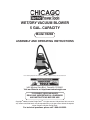
WET/DRY VACUUM BLOWER
5 GAL. CAPACITY
Model 94282
ASSEMBLY AND OPERATING INSTRUCTIONS
Do to continuing improvements, actual product may differ slightly from the product described herein.
®
3491 Mission Oaks Blvd., Camarillo, CA 93011
Visit our Web site at: http://www.harborfreight.com
TO PREVENT SERIOUS INJURY,
READ AND UNDERSTAND ALL WARNINGS
AND INSTRUCTIONS BEFORE USE.
Copyright© 2006 by Harbor Freight Tools®. All rights reserved. No portion of this manual or
any artwork contained herein may be reproduced in any shape or form without the express
written consent of Harbor Freight Tools.
For technical questions, please call 1-800-444-3353.
PRODUCT SPECIFICATIONS
Electrical Requirements 120 VAC / 60 Hz / 8 Amp / 3 HP Peak
Power Plug
3-Prong, Grounded
Power Cord
18 AWG x 3 C x 100” Long
Power Switch
2-Position Rocker w/Clear Plastic Cover
Tank Capacity
5 Gallons
Air Flow Capacity
125 Cubic Feet @ 21/2” Orifice
Additional Features
Float Valve to Stop Wet Vacuuming When Tank is Full
Built-In Storage for Power Cord and Accessories
Four Swivel Casters
Accessories
Three Extension Wands / One Crevice Tool
One Floor Nozzle / One Filter / One Dust Bag
Net Weight
11.7 Pounds
SAVE THIS MANUAL
You will need this manual for the safety warnings and precautions, assembly, operating, inspection, maintenance and cleaning procedures, parts list and assembly diagram.
Keep your invoice with this manual. Write the invoice number on the inside of the front
cover. Keep this manual and invoice in a safe and dry place for future reference.
GENERAL SAFETY RULES
WARNING!
READ AND UNDERSTAND ALL INSTRUCTIONS
Failure to follow all instructions listed below may result in
electric shock, fire, and/or serious injury.
SAVE THESE INSTRUCTIONS
WORK AREA
1.
Keep your work area clean and well lit. Cluttered benches and dark areas invite
accidents.
2.
Do not operate power tools in explosive atmospheres, such as in the presence of flammable liquids, gases, or dust. Power tools create sparks which may
ignite the dust or fumes.
3.
Keep bystanders, children, and visitors away while operating a power tool.
Distractions can cause you to lose control. Protect others in the work area from
debris such as chips and sparks. Provide barriers or shields as needed.
SKU 94282
For technical questions, please call 1-800-444-3353
PAGE ELECTRICAL SAFETY
1.
Grounded tools must be plugged into an outlet properly installed and grounded
in accordance with all codes and ordinances. Never remove the grounding
prong or modify the plug in any way. Do not use any adapter plugs. Check with
a qualified electrician if you are in doubt as to whether the outlet is properly
grounded. If the tools should electrically malfunction or break down, grounding
provides a low resistance path to carry electricity away from the user.
2.
Double insulated tools are equipped with a polarized plug (one blade is wider
than the other). This plug will fit in a polarized outlet only one way. If the plug
does not fit fully in the outlet, reverse the plug. If it still does not fit, contact
a qualified electrician to install a polarized outlet. Do not change the plug
in any way. Double insulation eliminates the need for the three wire grounded
power cord and grounded power supply system.
3.
Avoid body contact with grounded surfaces such as pipes, radiators, ranges,
and refrigerators. There is an increased risk of electric shock if your body is
grounded.
4.
Do not expose power tools to rain or wet conditions. Water entering a power
tool will increase the risk of electric shock.
5.
Do not abuse the Power Cord. Never use the Power Cord to carry the tools or
pull the Plug from an outlet. Keep the Power Cord away from heat, oil, sharp
edges, or moving parts. Replace damaged Power Cords immediately. Damaged Power Cords increase the risk of electric shock.
6.
When operating a power tool outside, use an outdoor extension cord marked
“W-A” or “W”. These extension cords are rated for outdoor use, and reduce the
risk of electric shock.
PERSONAL SAFETY
1.
Stay alert. Watch what you are doing, and use common sense when operating a power tool. Do not use a power tool while tired or under the influence
of drugs, alcohol, or medication. A moment of inattention while operating power
tools may result in serious personal injury.
2.
Dress properly. Do not wear loose clothing or jewelry. Contain long hair.
Keep your hair, clothing, and gloves away from moving parts. Loose clothes,
jewelry, or long hair can be caught in moving parts.
3.
Avoid accidental starting. Be sure the Power Switch is off before plugging
in. Carrying power tools with your finger on the Power Switch, or plugging in power
tools with the Power Switch on, invites accidents.
SKU 94282
For technical questions, please call 1-800-444-3353
PAGE 4.
Do not overreach. Keep proper footing and balance at all times. Proper footing
and balance enables better control of the power tool in unexpected situations.
5.
Use safety equipment. Always wear eye protection. Dust mask, non-skid safety
shoes, hard hat, or hearing protection must be used for appropriate conditions.
TOOL USE AND CARE
1.
Do not force the tool. Use the correct tool for your application. The correct
tool will do the job better and safer at the rate for which it is designed.
2.
Do not use the power tool if the Power Switch does not turn it on or off. Any
tool that cannot be controlled with the Power Switch is dangerous and must be
replaced.
3.
Disconnect the Power Cord Plug from the power source before making any
adjustments, changing accessories, or storing the tool. Such preventive safety
measures reduce the risk of starting the tool accidentally.
4.
Store idle tools out of reach of children and other untrained persons. Tools
are dangerous in the hands of untrained users.
5.
Maintain tools with care. Keep the Vacuum Blower clean. Properly maintained
tools are easier to control. Do not use a damaged tool. Tag damaged tools “Do not
use” until repaired.
6.
Check for misalignment or binding of moving parts, breakage of parts, and any
other condition that may affect the tool’s operation. If damaged, have the tool
serviced before using. Many accidents are caused by poorly maintained tools.
7.
Use only accessories that are recommended by the manufacturer for your
model. Accessories that may be suitable for one tool may become hazardous
when used on another tool.
SERVICE
1.
Tool service must be performed only by qualified repair personnel. Service or
maintenance performed by unqualified personnel could result in a risk of injury.
2.
When servicing a tool, use only identical replacement parts. Follow instructions in the “Inspection, Maintenance, And Cleaning” section of this manual.
Use of unauthorized parts or failure to follow maintenance instructions may create
a risk of electric shock or injury.
SKU 94282
For technical questions, please call 1-800-444-3353
PAGE SPECIFIC SAFETY RULES
1.
Maintain labels and nameplates on the Vacuum Blower. These carry important
information. If unreadable or missing, contact Harbor Freight Tools for a replacement.
2.
Always wear safety impact eye glasses when assembling and using
the Vacuum Blower. Using personal safety devices reduce the risk for
injury.
3.
Maintain a safe working environment. Keep the work area well lit. Make sure
there is adequate surrounding workspace. Always keep the work area free of obstructions, grease, oil, trash, and other debris. Do not use a power tool in areas
near flammable chemicals, dusts, and vapors. Do not use this product in a damp
or wet location.
4.
Do not force the Vacuum Blower. This tool will do the work better and safer at
the speed and capacity for which it was designed.
5.
Never leave the Vacuum Blower unattended when it is plugged into an electrical outlet. Turn off the tool, and unplug it from its electrical outlet before leaving.
6.
Avoid accidental electrical shock. Do not handle the Power Switch with wet
hands. Never plug the Power Cord of this product into an electrical outlet
while standing on a wet or damp surface. Plug the Power Cord of this unit only
into a 3-hole, 120 volt, Ground Fault Circuit Interrupter (GFCI), electrical outlet for
additional protection from electric shock.
7.
Do not unplug the Vacuum Blower by pulling on the Power Cord. Do not pull
or carry the Vacuum Blower by its Power Cord. Keep the Power Cord away from
sharp corners or edges.
8.
Industrial applications must follow OSHA guidelines.
9.
Always turn off the Vacuum Blower and unplug the unit from its electrical
outlet before performing any maintenance or changing accessories.
10.
Do not use the Vacuum Blower with any openings blocked. Keep free of dirt,
dust, lint, hair, and anything that may reduce air flow or hinder motor operation.
11.
Do not use the Vacuum Blower to pick up flammable or combustible
liquids such as gasoline. Do not use the Vacuum Blower in areas
where flammable or combustible liquids may be present. Do not use
the Vacuum Blower to pick up anything that is burning or smoking,
such as cigarettes, matches, or hot ashes.
12.
Do not use the Vacuum Blower as a sprayer of flammable liquids such as oil
base paints, lacquers, household cleaners, etc.
SKU 94282
For technical questions, please call 1-800-444-3353
PAGE 13.
Do not allow children to handle or play with this product.
14.
Do not use the Vacuum Blower without its Dust Bag and/or Filter in place.
15.
Do not use the Vacuum Blower if it has been dropped, damaged, left outdoors,
or immersed in liquid.
16.
Do not use the Vacuum Blower to pick up water from containers, i.e., sinks,
tubs, barrels, etc.
17.
Keep the end of the Hose and its accessories away from your face and
body.
18.
Avoid accidental falls. Use extra care when cleaning on stairways.
19.
Do not vacuum toxic, carcinogenic, combustible, or other hazardous materials
such as asbestos, arsenic, barium, beryllium, lead, pesticides, or other health
endangering materials.
20.
Do not expose the Vacuum Blower to rain. Store the unit indoors.
21.
WARNING! People with pacemakers should consult their physician(s) before using
this product. Electromagnetic fields in close proximity to a heart pacemaker could
cause interference to or failure of the pacemaker.
22.
WARNING! The warnings and cautions discussed in this manual cannot cover all
possible conditions and situations that may occur. It must be understood by the
operator that common sense and caution are factors which cannot be built into this
product, but must be supplied by the operator.
SAVE THESE INSTRUCTIONS
SKU 94282
For technical questions, please call 1-800-444-3353
PAGE GROUNDING
WARNING!
Improperly connecting the grounding wire can result in the risk of electric
shock. Check with a qualified electrician if you are in doubt as to whether
the outlet is properly grounded. Do not modify the power cord plug provided
with the tool. Never remove the grounding prong from the plug. Do not use
the tool if the power cord or plug is damaged. If damaged, have it repaired
by a service facility before use. If the plug will not fit the outlet, have a proper
outlet installed by a qualified electrician.
GROUNDED TOOLS: TOOLS WITH THREE PRONG PLUGS
1.
Tools marked with “Grounding Required” have a three wire cord and three prong
grounding plug. The plug must be connected to a properly grounded outlet. If
the tool should electrically malfunction or break down, grounding provides a low
resistance path to carry electricity away from the user, reducing the risk of electric
shock. (See Figure A.)
2.
The grounding prong in the plug is connected through the green wire inside the
cord to the grounding system in the tool. The green wire in the cord must be the
only wire connected to the tool’s grounding system and must never be attached to
an electrically “live” terminal. (See Figure A.)
3.
Your tool must be plugged into an appropriate outlet, properly installed and grounded
in accordance with all codes and ordinances. The plug and outlet should look like
those in the following illustration. (See Figure A.)
THIS PRODUCT USES A
3-PRONG PLUG
120 VOLT,
GROUNDED,
ELECTRICAL OUTLET
FIGURE A
SKU 94282
For technical questions, please call 1-800-444-3353
PAGE DOUBLE INSULATED TOOLS: TOOLS WITH TWO PRONG PLUGS
1.
Tools marked “Double Insulated” do not require grounding. They have a special
double insulation system which satisfies OSHA requirements and complies with
the applicable standards of Underwriters Laboratories, Inc., the Canadian Standard
Association, and the National Electrical Code. (See Figure C.)
2.
Double insulated tools may be used in either of the 120 volt outlets shown in the
following illustration. (See Figure B.)
120 VOLT,
GROUNDED,
ELECTRICAL OUTLET
120 VOLT,
GROUNDED,
ELECTRICAL OUTLET
FIGURE B
EXTENSION CORDS
1.
Grounded tools require a three wire extension cord. Double Insulated tools can
use either a two or three wire extension cord.
2.
As the distance from the supply outlet increases, you must use a heavier gauge
extension cord. Using extension cords with inadequately sized wire causes a serious drop in voltage, resulting in loss of power and possible tool damage.
(See Figure C, next page.)
3.
The smaller the gauge number of the wire, the greater the capacity of the cord. For
example, a 14 gauge cord can carry a higher current than a 16 gauge cord.
(See Figure C.)
4.
When using more than one extension cord to make up the total length, make sure
each cord contains at least the minimum wire size required.
(See Figure C.)
5.
If you are using one extension cord for more than one tool, add the nameplate amperes and use the sum to determine the required minimum cord size.
(See Figure C.)
6.
If you are using an extension cord outdoors, make sure it is marked with the suffix
“W-A” (“W” in Canada) to indicate it is acceptable for outdoor use.
SKU 94282
For technical questions, please call 1-800-444-3353
PAGE 7.
Make sure your extension cord is properly wired and in good electrical condition.
Always replace a damaged extension cord or have it repaired by a qualified electrician before using it.
8.
Protect your extension cords from sharp objects, excessive heat, and damp or wet
areas.
RECOMMENDED MINIMUM WIRE GAUGE FOR EXTENSION CORDS*
(120 or 240 VOLT)
NAMEPLATE
AMPERES
(At Full Load)
25 Feet
50 Feet
75 Feet
100 Feet
150 Feet
0 – 2.0
18
18
18
18
16
2.1 – 3.4
18
18
18
16
14
3.5 – 5.0
18
18
16
14
12
5.1 – 7.0
18
16
14
12
12
7.1 – 12.0
18
14
12
10
-
12.1 – 16.0
14
12
10
-
-
16.1 – 20.0
12
10
-
-
-
FIGURE C
EXTENSION CORD LENGTH
* Based on limiting the line voltage drop to five volts at
150% of the rated amperes.
SYMBOLOGY
Double Insulated
Canadian Standards Association
Underwriters Laboratories, Inc.
V~
A
n0 xxxx/min.
SKU 94282
Volts Alternating Current
Amperes
No Load Revolutions per Minute (RPM)
For technical questions, please call 1-800-444-3353
PAGE UNPACKING
When unpacking, check to make sure all the parts shown on the Parts List on page
14 are included. If any parts are missing or broken, please call Harbor Freight Tools at
the number shown on the cover of this manual as soon as possible.
ASSEMBLY INSTRUCTIONS
CAUTION! Always make sure the Power Switch (2) of the Vacuum Blower is
in its “OFF” position and the tool is unplugged from its electrical outlet prior to assembling the tool, adding any accessories, or making adjustments to the tool.
To Attach The Wheel Casters:
1.
Open the Upper Clasps (11) located on each side of the Tank (15). Then lift and
remove the Upper Cover (3) from the Vacuum Blower. Then, turn the Tank upside
down. (See Figure E.)
2.
Firmly insert one Caster (16) into each of the four Caster Supports (17).
(See Figure E.)
3.
Insert the four Caster Supports (17) into the slots located at the bottom of the Tank
Base (18). Then secure the Caster Supports to the Tank Base, using one Screw
(103) for each Caster Support. (See Figure E.)
4.
Turn the Tank (15) right side up so that it rests upon its four Casters (16).
UPPER COVER (3)
CASTER (16)
UPPER CLASP (11)
CASTER SUPPORT
(17)
SCREW (103)
FIGURE E
To Install A Foam Filter, Dust Bag, Or Dry Filter:
1.
Open the Upper Clasps (11) located on each side of the Tank (15). Then lift and
remove the Upper Cover (3) from the Vacuum Blower. (See Figure F.)
2.
The Foam Filter (107) is used only for wet vacuuming. To install the Foam Filter,
insert the Foam Filter over the Filter Basket (21). Then, replace the Upper Cover
(3) onto the Vacuum Blower. (See Figure F.)
SKU 94282
For technical questions, please call 1-800-444-3353
PAGE 10
3.
The Dust Bag (108) is used only for dry vacuuming. To install the Dust Bag, insert
its opening over the portion of the Suction Port (13) protruding from within the Tank
(15) of the Vacuum Blower. Then, replace the Upper Cover (3) onto the Vacuum
Blower. (See Figure F.)
4.
The Dry Filter (109) is used only for dry vacuuming. To install the Dry Filter, first
make sure that the foam filter is clean, dry, and in place over the filter basket. Then,
slide the Dry Filter over the Filter Basket (21). Then, replace the Upper Cover (3)
onto the Vacuum Blower. (See Figure F.)
FILTER
BASKET
(21)
FOAM FILTER (107)
DUST BAG
(108)
SUCTION PORT
(13)
FIGURE F
DRY FILTER
(109)
OPERATING INSTRUCTIONS
To Vacuum:
1.
Connect the larger end of the Hose (110) to the Suction Port (13) of the Vacuum Blower. Next, connect one or more Extension Wands (105) to the smaller end of the Hose. Then, depending on the job at hand, connect the Crevice Tool (106) or Floor Nozzle (104) to the Extension Wand. (See Figure G, page 13.)
2.
NOTE:
A. Use the Extension Wands (105) to reach inaccessible spots and to eliminate
bending over to clean low areas.
B. Use the Crevice Tool (106) to vacuum hard-to-reach areas.
C. Use the Floor Nozzle (104) to vacuum upholstery, carpet, and floor mats of your
vehicle’s interior.
3.
Make sure the Power Switch (2) of the Vacuum Blower is in its “OFF” position.
4.
Plug the unit’s Power Cord (30) into the nearest 120 volt, grounded, electrical outlet.
(See Figure G, next page.)
5.
Then turn the Power Switch (2) of the Vacuum Blower to its “ON” position to begin
vacuuming. (See Figure G.)
SKU 94282
For technical questions, please call 1-800-444-3353
PAGE 11
6.
IMPORTANT: If wet vacuuming, make sure to turn off and unplug the unit frequently
during use. Remove the Upper Cover (3) and empty the water in the Tank (15).
Once empty, replace the Upper Cover onto the Tank. Plug the unit’s Power Cord
(30) back into its electrical outlet, and turn on the unit to resume vacuuming. NOTE:
The unit has a built-in float valve which, when the Tank becomes full of water, will
automatically turn off the unit. To restart the unit, follow the instructions previously
mentioned above.
7.
When finished vacuuming, turn the Power Switch (2) to its “OFF” position. Then,
disconnect the Power Cord (30) from its electrical outlet. (See Figure G.)
To Use As A Blower:
1.
CAUTION! Never use the Floor Nozzle (104) or Crevice Tool (106) when using
the unit as a blower. (See Figure G.)
2.
IMPORTANT: Before using the unit as a blower, make sure to remove the Foam
Filter (107), Dust Bag (108), and Dry Filter (109) from the Filter Basket (21) and
Suction Port (13). Failure to do so may overheat and damage the Motor.
(See Figure F.)
3.
Connect the larger end of the Hose (110) to the Blower Port (4) of the unit. Next,
connect one or more Extension Wands (105) to the smaller end of the Hose.
(See Figure G.)
4.
Plug the unit’s Power Cord (30) into the nearest 120 volt, grounded, electrical outlet.
(See Figure G.)
5.
Then turn the Power Switch (2) of the Vacuum Blower to its “ON” position to begin
blowing. (See Figure G.)
6.
When using the unit as a blower, DO NOT aim the Hose (110) or Extension Wands
(105) toward yourself or another person. (See Figure G.)
7.
When finished using the unit as a blower, turn the Power Switch (2) to its “OFF”
position. Then, disconnect the Power Cord (30) from its electrical outlet.
(See Figure G.)
SKU 94282
For technical questions, please call 1-800-444-3353
PAGE 12
FIGURE G
POWER SWITCH
(2)
BLOWER PORT
(4)
SUCTION PORT
(13)
POWER CORD
(30)
HOSE
(110)
FLOOR NOZZLE
(104)
EXTENSION WAND
(105)
EXTENSION WAND
(105)
EXTENSION WAND
CREVICE TOOL
(105)
(106)
INSPECTION, MAINTENANCE, AND CLEANING
1.
WARNING! Make sure the Power Switch (2) of the Vacuum Blower is in its
“OFF” position and the tool is unplugged from its electrical outlet before performing
any inspection, maintenance, or cleaning procedures.
2.
Before each use, inspect the general condition of the Vacuum Blower. Check for
misalignment or binding of moving parts, cracked or broken parts, damaged electrical wiring, plugged Hoses or suction/blower Ports, and any other condition that
may affect safe operation. If abnormal noise or vibration occurs, have the problem
corrected before further use. Do not use damaged equipment.
3.
After each use, empty the Tank (15) of the unit and check to make sure the Foam
Filter (107), Dust Bag (108), or Dry Filter (109) being used is cleaned and/or emptied.
4.
To clean the exterior parts of the Vacuum Blower and its accessories, use only
a clean cloth and mild detergent. Do not immerse any electrical part of the Vacuum
Blower in any liquids.
5.
CAUTION! All maintenance, service, or repairs not mentioned in this
manual must only be performed by a qualified service technician.
SKU 94282
For technical questions, please call 1-800-444-3353
PAGE 13
PLEASE READ THE FOLLOWING CAREFULLY
THE MANUFACTURER AND/OR DISTRIBUTOR HAS PROVIDED THE PARTS LIST AND ASSEMBLY DIAGRAM
IN THIS MANUAL AS A REFERENCE TOOL ONLY. NEITHER THE MANUFACTURER OR DISTRIBUTOR MAKES
ANY REPRESENTATION OR WARRANTY OF ANY KIND TO THE BUYER THAT HE OR SHE IS QUALIFIED TO
REPLACE ANY PARTS OF THE PRODUCT. IN FACT, THE MANUFACTURER AND/OR DISTRIBUTOR EXPRESSLY STATES THAT ALL REPAIRS AND PARTS REPLACEMENTS SHOULD BE UNDERTAKEN BY CERTIFIED AND
LICENSED TECHNICIANS, AND NOT BY THE BUYER. THE BUYER ASSUMES ALL RISKS AND LIABILITY ARISING OUT OF HIS OR HER REPAIRS TO THE ORIGINAL PRODUCT OR REPLACEMENT PARTS THERETO, OR
ARISING OUT OF HIS OR HER INSTALLATION OF REPLACEMENT PARTS THERETO.
TROUBLESHOOTING
Problem
Possible Solution
Power switch does not turn unit on.
1. Make sure power plug is plugged into a working, 120 volt, grounded, electrical outlet.
2. Tank full of water. Empty tank.
3. Have a qualified service technician check out the power switch, wiring, and motor.
Unit shuts down while in use.
1. Prolonged use may cause temporary overheating of motor. Turn unit off, and allow unit
to cool down before restarting.
Unit has suction, but does not clean
when hose or other attachments are
connected.
1. Hose and/or attachment may be cracked or damaged. Replace hose and/or attachment.
2. Hose and/or attachment may be clogged. Remove hose and attachment from suction
port and connect to blower port. Then, blow out the hose and attachment.
Unit has no suction.
1. Thoroughly clean suction/blower ports, foam filter, and dust bag.
Dust comes from the motor cover.
1. Dust bag missing or damaged. Install or replace dust bag.
PARTS LIST
Part
Description
Part
Description
Part
Description
1
Handle
16
Caster
31
Air Outlet Foam
2
Power Switch
17
Caster Support
32
Air Outlet Foam Support
3
Upper Cover
18
Tank Base
33
Motor Set
4
Blower Port
19
Cord Hook
34
Sealing
5
Seal
20
Valve
101
Screw (ST4.2 x 16)
6
Anti-Noise Foam
21
Tray
102
Screw (ST4.2 x 14)
7
Air Block Board
22
Seal
103
Screw (ST4.2 x 16)
8
Press Board
23
Lower Cover
104
Floor Nozzle
9
Waterproof Foam
24
Inductor & Capacitor Set
105
Extension Wand (x3)
10
Seal Ring
25
Cord Anchor
106
Crevice Tool
11
Clasp (Upper Part)
26
Cable Sleeve
107
Foam Filter
12
Clasp (Lower Part)
27
Air Block Board
108
Dust Bag
13
Suction Port
28
Fence
109
Dry Filter
14
Suction Seat Press Board
29
Foam
110
Hose
15
Tank
30
Power Cord
SKU 94282
For technical questions, please call 1-800-444-3353
PAGE 14
ASSEMBLY DIAGRAM
104
110
106
107
105
108
109
NOTE:
Some parts are listed and shown for illustration purposes only, and are not available individually
as replacement parts.
SKU 94282
For technical questions, please call 1-800-444-3353
PAGE 15
LIMITED 90 DAY WARRANTY
Harbor Freight Tools Co. makes every effort to assure that its products meet high quality and durability standards,
and warrants to the original purchaser that this product is free from defects in materials and workmanship for
the period of ninety days from the date of purchase. This warranty does not apply to damage due directly or
indirectly, to misuse, abuse, negligence or accidents, repairs or alterations outside our facilities, or to lack of
maintenance. We shall in no event be liable for death, injuries to persons or property, or for incidental, contingent,
special or consequential damages arising from the use of our product. Some states do not allow the exclusion
or limitation of incidental or consequential damages, so the above limitation of exclusion may not apply to you.
THIS WARRANTY IS EXPRESSLY IN LIEU OF ALL OTHER WARRANTIES, EXPRESS OR IMPLIED,
INCLUDING THE WARRANTIES OF MERCHANTABILITY AND FITNESS.
To take advantage of this warranty, the product or part must be returned to us with transportation charges
prepaid. Proof of purchase date and an explanation of the complaint must accompany the merchandise. If our
inspection verifies the defect, we will either repair or replace the product at our election or we may elect to
refund the purchase price if we cannot readily and quickly provide you with a replacement. We will return
repaired products at our expense, but if we determine there is no defect, or that the defect resulted from
causes not within the scope of our warranty, then you must bear the cost of returning the product.
This warranty gives you specific legal rights and you may also have other rights which vary from state to state.
3491 Mission Oaks Blvd. • PO Box 6009 • Camarillo, CA 93011 • (800) 444-3353
SKU 94282
For technical questions, please call 1-800-444-3353
PAGE 16