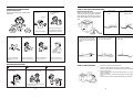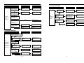
1
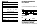
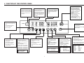
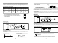
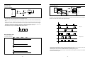
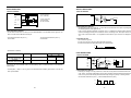
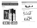
Service Manual
Programmable Wahing Machine
DWF-7588TE/NE/ME
8088TE/NE/ME
9288TE/NE/ME
1088TE/NE/ME
DAEWOO ELECTRONICS CO., LTD.
686, AHYEON-DONG, MAPO-GU,
SEOUL, KOREA
C.P.O. BOX 8003 SEOUL, KOREA
TELEX: DWELEC K28177-8
CABLE: “DAEWOOELEC”
FAX: 02) 364-5588/5305
TEL: 02) 360-7114/7315~7
S/M NO.: WF 10880100
DAEWOO ELECTRONICS CO., LTD.
PRINTED DATE: MAR.1996
TABLE OF CONTENTS
1. SPECIFICATIONS . . . . . . . . . . . . . . . . . . . . . . . . . . . . . . . . . . . . . . . . . . . . . . . . . . . . . . . . . . . . . . . . . 2
2. FEATURE AND TECHNICAL EXPLANATION
FEATURE OF THE WASHING MACHINE . . . . . . . . . . . . . . . . . . . . . . . . . . . . . . . . . . . . . . . . . . . 3
WATER CURRENTS RENTS TO ADJUST THE UNBALANCED LOAD . . . . . . . . . . . . . . . . . . . 3
FUNCTION FOR SOAK WASH . . . . . . . . . . . . . . . . . . . . . . . . . . . . . . . . . . . . . . . . . . . . . . . . . . . 3
AUTOMATIC WATER SUPPLY SYSTEM FOR BLANKET WASH . . . . . . . . . . . . . . . . . . . . . . . . 3
PULSATOR SYSTEM . . . . . . . . . . . . . . . . . . . . . . . . . . . . . . . . . . . . . . . . . . . . . . . . . . . . . . . . . . . 4
AUTOMATIC DRAINING TIME ADJUSTMENT . . . . . . . . . . . . . . . . . . . . . . . . . . . . . . . . . . . . . . . 4
SOFTENER DISPENSER . . . . . . . . . . . . . . . . . . . . . . . . . . . . . . . . . . . . . . . . . . . . . . . . . . . . . . . . 5
AUTOMATIC UNBALANCE ADJUSTMENT . . . . . . . . . . . . . . . . . . . . . . . . . . . . . . . . . . . . . . . . . 6
CIRCULATING-WATER COURSE AND LINT FILTER . . . . . . . . . . . . . . . . . . . . . . . . . . . . . . . . . 6
RESIDUAL TIME DISPLAY . . . . . . . . . . . . . . . . . . . . . . . . . . . . . . . . . . . . . . . . . . . . . . . . . . . . . . 7
DRAIN MOTOR . . . . . . . . . . . . . . . . . . . . . . . . . . . . . . . . . . . . . . . . . . . . . . . . . . . . . . . . . . . . . . . . 7
GEAR MECHANISM ASS’Y . . . . . . . . . . . . . . . . . . . . . . . . . . . . . . . . . . . . . . . . . . . . . . . . . . . . . . 8
PRINCIPLE OF BUBBLE GENERATOR . . . . . . . . . . . . . . . . . . . . . . . . . . . . . . . . . . . . . . . . . . . . 8
FUNCTIONAL PRINCIPLE OF BUBBLE WASHING MACHINE . . . . . . . . . . . . . . . . . . . . . . . . . 9
3. STRUCTURE OF THE WASHING MACHINE . . . . . . . . . . . . . . . . . . . . . . . . . . . . . . . . . . . . . . . . . . 10
4. FUNCTIONS OF THE CONTROL PANEL . . . . . . . . . . . . . . . . . . . . . . . . . . . . . . . . . . . . . . . . . . . . . 11
5. DIRECTIONS FOR INSTALLATION AND USE
HOW TO INSTALL THE WASHING MACHINE . . . . . . . . . . . . . . . . . . . . . . . . . . . . . . . . . . . . . . 13
HOW TO CONNECT THE INLET HOSE . . . . . . . . . . . . . . . . . . . . . . . . . . . . . . . . . . . . . . . . . . . 14
PREPARATION FOR WASHING . . . . . . . . . . . . . . . . . . . . . . . . . . . . . . . . . . . . . . . . . . . . . . . . . 15
HOW TO USE AND JOIN DRAIN HOSE . . . . . . . . . . . . . . . . . . . . . . . . . . . . . . . . . . . . . . . . . . . 16
HOW TO REROUTE THE DRAIN HOSE . . . . . . . . . . . . . . . . . . . . . . . . . . . . . . . . . . . . . . . . . . 17
6. PROCEDURE OF FULL-AUTOMATIC WASHING . . . . . . . . . . . . . . . . . . . . . . . . . . . . . . . . . . . . . . . 18
7. DIRECTIONS FOR DISASSEMBLY AND ADJUSTMENT
GEAR MECHANISM . . . . . . . . . . . . . . . . . . . . . . . . . . . . . . . . . . . . . . . . . . . . . . . . . . . . . . . . . . . 20
DRAIN MOTOR . . . . . . . . . . . . . . . . . . . . . . . . . . . . . . . . . . . . . . . . . . . . . . . . . . . . . . . . . . . . . . . 21
BRAKE ADJUSTMENT . . . . . . . . . . . . . . . . . . . . . . . . . . . . . . . . . . . . . . . . . . . . . . . . . . . . . . . . . 21
8. TROUBLE SHOOTING GUIDE
CONCERNING WATER SUPPLY . . . . . . . . . . . . . . . . . . . . . . . . . . . . . . . . . . . . . . . . . . . . . . . . 22
CONCERNING WASHING . . . . . . . . . . . . . . . . . . . . . . . . . . . . . . . . . . . . . . . . . . . . . . . . . . . . . . 23
CONCERNING DRAINING . . . . . . . . . . . . . . . . . . . . . . . . . . . . . . . . . . . . . . . . . . . . . . . . . . . . . . 24
CONCERNING SPINING . . . . . . . . . . . . . . . . . . . . . . . . . . . . . . . . . . . . . . . . . . . . . . . . . . . . . . . 25
CONCERNING OPERATION . . . . . . . . . . . . . . . . . . . . . . . . . . . . . . . . . . . . . . . . . . . . . . . . . . . . 26
9. PRESENTATION OF THE P.C.B. ASS’Y
CONCERNING ERROR MESSAGE . . . . . . . . . . . . . . . . . . . . . . . . . . . . . . . . . . . . . . . . . . . . . . 27
CONFIGURATION OF FULL CIRCUITS . . . . . . . . . . . . . . . . . . . . . . . . . . . . . . . . . . . . . . . . . . . .28
MINUTE EXPLANATION DIAGRAM FOR EACH PARTS . . . . . . . . . . . . . . . . . . . . . . . . . . . . . . 29
APPENDIX
WIRING DIAGRAM . . . . . . . . . . . . . . . . . . . . . . . . . . . . . . . . . . . . . . . . . . . . . . . . . . . . . . . . . . . . 46
PARTS LIST . . . . . . . . . . . . . . . . . . . . . . . . . . . . . . . . . . . . . . . . . . . . . . . . . . . . . . . . . . . . . . . . . .47
PART DIAGRAM . . . . . . . . . . . . . . . . . . . . . . . . . . . . . . . . . . . . . . . . . . . . . . . . . . . . . . . . . . . . . .53
P.C.B. PARTS LIST . . . . . . . . . . . . . . . . . . . . . . . . . . . . . . . . . . . . . . . . . . . . . . . . . . . . . . . . . . . .56
CIRCUIT DIAGRAM . . . . . . . . . . . . . . . . . . . . . . . . . . . . . . . . . . . . . . . . . . . . . . . . . . . . . . . . . . . .60
BARE PCB(TOP) . . . . . . . . . . . . . . . . . . . . . . . . . . . . . . . . . . . . . . . . . . . . . . . . . . . . . . . . . . . . . .62
BARE PCB (BOTTOM) . . . . . . . . . . . . . . . . . . . . . . . . . . . . . . . . . . . . . . . . . . . . . . . . . . . . . . . . .63
1
1.SPECIFICATIONS
NO.
ITEM
2. FEATURE AND TECHNICAL EXPLANATION
DWF-7588TE/NE/ME DWF-8088TE/NE/ME
1 POWER SOURCE
DWF/9288TE/NE/ME
DWF-1088TE/NE/ME
AVAILABLE IN ALL LOCAL AC VOLTAGE AND CYCLE
2 POWER CONSUMPTION
INPUT : 400W
OUTPUT : 210W
INPUT:460W
OUTPUT:280W
3 MACHINE WEIGHT
49KG
50KG
54KG
55KG
(GROSS WEIGHT:63KG)
(GROSS WEIGHT:64KG)
(GROSS WEIGHT:59KG) (GROSS WEIGHT:60KG)
4 DIMENSION (WXHXD)
5 WASHING COURSE
610 X 962 X 655mm
628 X 1005 X 673mm
FULL AUTOMATIC 9 OF COURSE (FUZZY, MEMORY, SOAK, DRY, SILK,
ECONOMIC, HEAVY, NIGHT, BLANAKET)
6 WATER CONSUMPTION
7 WATER LEVEL SELECTOR
NORMAL 259L
NORMAL 265L
NORMAL 304L
NORMAL 315L
HIGH(80L), MID(68L),
HIGH(82L), MID(70L),
HIGH(93L), MID(78L),
HIGH(96L), MID(81L),
LOW(55L), SMALL(42L),
LOW(57L), SMALL(43L),
LOW(61L), SMALL(48L),
LOW(65L), SMALL(49L),
E.SMALL(30.5L)
E.SMALL(31.5L)
E.SMALL(33L)
E.SMALL(36L)
0.3kg/cm2~8kg/cm2 (2.94 N/cm2~78.4N/cm2)
8 OPERATING WATER PRESSURE
9 REVOLUTION PER MINUTE
FEATURE OF THE WASHING MACHINE
1) The first air bubble washing system in the world.
2) Quiet washing through the innovational low-noise design.
3) The wash effectiveness is much more enhanced because of the air bubble washing system.
4) The laundry detergent dissolves well in water because of the air bubble washing system.
5) The adoption of the water currents to adjust the unbalanced load.
6) One-touch operation system.
WATER CURRENT TO ADJUST THE UNBALANCED LOAD
It is a function to prevent eccentricity of the clothes after wash by rotating pulsator C.W and C.C.W for 20
seconds.(But, the DRY & SILK course have no operation of the water currents to adjust the unbalnced
load.)
EFFECT
It reduces vibration and noise effectively while spinning.
WATER FLOW
WASH
DRAIN
SPIN
FILL
RINSE 1
DRAIN
SPIN
FILL
RINSE 2
0.5
•••••••
DRAIN
•••
SPIN :780r.p.m., WASH : 140 r.p.m.(60Hz); SPIN : 680 r.p.m., WASH : 130r.p.m.(50Hz)
AT DRY, SILK COURSE 60 r.p.m. (60Hz), 70 r.p.m.(50Hz)
10 PULSATOR
6 WINGS (Ø 376mm)
11 WATER LEVEL CONTROL
ELECTRONICAL SENSOR
12 OUTER CABINET
13 ANT-NOISE PLATE
6 WINGS (Ø 396mm)
MOTOR
C.W
SINGAL
C.C.W
PCM (PRE-COATED METAL) SHEET
O
O
14 GEAR MECHANISM ASS’Y
O
TIME(SEC.)
0.3
0.5
0.3
0.5
O
20 SEC. (About 13 Times)
HELICAL GEAR FOR LOW NOISE
15 LINT FILTER
O
O
O
O
16 SOFTENER INLET
O
O
O
O
17 FUNCTION FOR SOAK WASH
O
O
O
O
18 ALARM SIGNAL
O
O
O
O
19 RESIDUAL TIME DISPLAY
O
O
O
O
20 AUTO. WATER SUPPLY
O
O
O
O
21 NEW WATER FLOW
WATER FLOW FOR ADJUST THE UNBALANCED LOAD
22 ECONOMIC COURSE
O
23 FUNCTION FOR BUBBLE
O
24 AUTO RE-FEED WATER
25 AUTO POWER OFF
0.3
O
O
O
O
O
O
O
O
O
O
O
FUNCTION FOR SOAK WASH
DISPLAY THE RESIDUAL TIME
When the SOAK WASH is selected, the total wash time increases because 60 minutes for soak process
are added to the time of main process.
PROGRESS
SOAK PROCESS
MAIN PROCESS
FILL
WASH
STOP
WASH
STOP
WASH
STOP
•
1’
19’
1’
19’
1’
19’
60 Minutes
NOTE: ‘ ’ mark indicates the operation of the water currents to adjust the unbalanced load.
AUTOMATIC WATER SUPPLY SYSTEM FOR BLANKET WASH
The water level would be lowered because the blanket absorbs water at the beginning of washing.
Therefore, after 30 seconds, the operation is interrupted to check the water level, and then the water is
supplied again until the selected water level is reached.
2
3
PULSATOR SYSTEM
SOFTENER DISPENSER
When the new shaped pulsator is rotated C.W or C.C.W at a high speed, it makes the ‘heart-shaped’
water currents as shown below.
This is the device to dispense the softener automatically by centrifugal force.
This is installed inside the auto-balancer.
C
FUNCTIONAL PRINCIPLE
1) Softener stays in room (A) when poured into softener inlet.
2) Softener moves from (A) to (B) by centrifugal force during intermittent spin process.
3) Softener flows from (B) to (C) during rinse process next to intermittent spin.
4) Softener moves from (C) to (D) by centrigfugal force during second intermittent spin.
After spin process is finished, the softener is added into the tub through softener outlet.
WATER CURRENTS
A
Rotate
B
B
A
A
C
Water is pushed up near the tub
wall by rotation of the pulsator.
Water is pulled down in the
middle of the tub by rotation of
the pulsator.
Water currents is generated by
rotation of the pulsator.
FLOW OF THE SOFTENER
Wash
AUTOMATIC DRAINING TIME ADJUSTMENT
Normal
This system adjusts the draining time automatically according to the draining condition.
Draining
condition
Good draining
The washer begins spin process after drainage.
Bad draining
Draininig time is prolonged.
No draining
Program is stopped and gives the alarm.
Course
Intermittent
Spin
Centrifugal
force
(A)
(B)
Hold
Intermittent
Spin
Rinse
Flow in
Centrifugal
force
Flow in
(C)
Spin
(D)
FLOW OF THE SOFTENER INSIDE OF THE BALANCER
FUNCTIONAL PRINCIPLE
1) The micom can remember the time from the begining of drain to reset point when the pressure switch
reaches to “OFF” point
Drain Time
Movement of the Program
Room inside
the balancer
A
B
C
D
Centrifugal force
Flowing by weight
Less than
Continue draining
4 minutes
More than
Program stops and gives the alarm with
blinked on display lamp.
NOTE : Softener moves into the next room when r.p.m of the tub is more than 100 r.p.m.
4 minutes
HOW TO CHECK MOVEMENT
Pour a reasonable amount of “MILK” into softener
dispenser and operate the washer with no load. In
final rinse cycle, make sure that the milk is added into
the tub through softener outler.
2) In case of continuous draining, residual drain time is determined by micom.
Draining time as a whole = D + 60
Residual drain time.
The time remembered by micom.
(T sec.)
D
R
A
I
N
I
N
G
T
I
M
E
(mm)
400
TRIP POINTS
340
D3
T3
220
D2
D1
T2
60
T1
RESET POINTS
60
E.LOW
LOW
MID
Balancer
Softener
outlet
280
D4
T4
W
A
T
E
R
B
L
E
V
E
L
A
Softener inlet
0
HIGH
T1=D1+60 (Sec.) T2=D2+60(Sec.) T3=D3+60(Sec.) T4=D4+60(Sec.)
4
5
D
C
AUTOMATIC UNBALANCE ADJUSTMENT
LINT FILTER
This system is to prevent abnormal vibration during intermittent spin and spin process.
Much lint may be obtained according to the kind of
clothes to be washed and some of the lint may also
sticks to the clothes.
To minimize this possibility a lint filter is provided on
the upper part of the tub to filter the wash water as it
is discharged from the water channel. It is good to
use the lint filter during washing.
FUNCTIONAL PRINCIPLE
1) Always the safety switch contact is “ON”
position.
2) In case that wash loads get uneven
during spin, the outer tub hits the safety
switch due to the serious vibration, and
the spin process is interrupted.
3) In case that P.C.B. ASS’Y gets “OFF”
signal from the safety switch, spin
process are stopped and rinse process
is started automatically by P.C.B.
ASS’Y.
4) If the safety switch is operated due to
the unbalance of the tub, the program is
stopped and the alarm is given.
Contact of safety switch
Filter
Bleach Inlet
Pulsator
HOW TO REPLACE LINT FILTER
1) Pull the filter frame upward.
2) Turn the lint filter inside out, and wash the lint off with water.
3) Return the filter as it was, and fix the filter frame to the slot.
Contact lever A
Position of
unbalanced load
(OFF)
RESIDUAL TIME DISPLAY
Normal (ON)
NOTE:
The alarm finished when you close the lid after opening
it. Check the unbalance of the wash load and the
installation condition.
When the START/HOLD button is pressed, the residual time (min.) is displayed on the time indicator, and
it will be counted down according to process.
When operation is finished, the TIME INDICATOR will light up
.
DRAIN MOTOR
STRUCTURE
CIRCULATING-WATER COURSE AND LINT FILTER
CIRCULATING-WATER
The washing and rinsing effects have
been improved by adopting the water
system in which water in the tub is
circulated in a designed pattern.
When the pulsator rotates during the
washing or rinsing process, the water
below the pulsator vanes creates a water
currents as shown in figure.
The water is then discharged from the
upper part of the tub through the water
channel. About 40 L/min. water is
circulated at the ‘high’ water level,
standard wash load and standard water
currents.
Pull
Loosen
Pulley
Lever
Tub
Inductive ring
Magnet
Filter
Outer tub
Coil of motor
Magnet of motor
Water
channel
Pulsator
FUNCTIONAL PRINCIPLE
1) When the DRAIN MOTOR connected to the power source(A.C 220V), the DRAIN MOTOR rotates with
900 r.p.m and revolves the pulley by gear assembly for reducing.
2) When the pulley is rotated, the pulley winds the wire to open the drain valve.
3) Therefore, rotation of pulley changed to the linear moving of wire.
4) The wire pulls the brake lever of Gear Mechanism Ass’y within 5 seconds.
5) After the wire pulled, gear assembly is separated from motor and condition of pulling is held by
operation of the lever.
6) When the power is turned off, the drain valve is closed because the wire returns to original position.
6
7
GEAR EMCHANISM ASS’Y
The proper water currents is made by the rotation of pulsator at a low speed (about 140 r.p.m) to prevent
the damage to the small sized clothes.
PRINCIPLE OF INTAKE & OUTLET OF THE AIR
INTAKE : ARMATURE moves up, and BELLOWS inhales the air. At the same time, protector B is open
and A is close.
OUTLET : ARMATURE moves down, and BELLOWS exhausts the air. At the same time, protector B is
close and A is opend.
Pulsator shaft
FUNCTIONAL PRINCIPLE OF TRANS & MAGNET
The phase of A.C electric power changes to 60 cycle/second.
The magnetic pole of trans core is changed by the change of the phase of A.C electric power.
The core repeats push and pull (3600 times/min.) of the at mature magnet.
Spinner shaft
•
•
•
Inner clutch spring
Planetary gear
Sun gear
Internal gear
Planetary gear
Clutch spring
Brake lever
Clutch boss
A.C
A.C
Spinner pulley
N
Pulsator
Motor
NS
1490 r.p.m
(50Hz)
Planetary gear
Motor
S
LEAF SPRING
TRANS CORE
S
NS
N
MAGNET
1 revolution
Planetary Gear
Pulsator
Spinner Pulley
1/5.2
130 r.p.m
750 r.p.m
Directly
5.2 revolutions
Spinner
pulley
FUNCTIONAL PRINCIPLE OF BUBBLE WASHING MACHINE
Tub
ACROSS SECTION
750 r.p.m
V-belt
Air bubble
PRINCIPLE OF BUBBLE GENERATOR
STRUCTURE
Tub
Outer tub
Bobbin & coil
Armature
Magnet
Bellows
Trans core
Pulsator
Nozzle
Air
Air
Air out hole
Protector A
Air in hole
Protector B
8
FUNCTIONAL PRINCIPLE
Bubble generator supplies the air from the bottom of outer tub to the inner space of pulsator, the air is
dispersed by the rotation of pulsator. Air-bubble is created by the centrifugal force, and rises up.
9
3. STRUCTURE OF THE WASHING MACHINE
• HOT WATER TAP
• COLD WATER TAP
After using the washer, close the water
tap and turn off the power
After using the washer, close the water
tap and turn off the power.
• TUB
• SOFTNER INLET
Pour softener into the softener inlet just
before wash and it will be added into
the tub automatically just before the
the final rinse.
• BLEACH INLET
•HOOK HOLE
• POWER SWITCH
•LINT FILTER
• CONTROL PANEL
•PULSATOR
•UNDER BASE COVER
•POWER CORD
• MOTOR
•EARTH
• ADJUSTABLE LEGS
•HOSE DRAIN
ACCESSORIES
WATER TAP ADAPTER(2PCS)
BASKET
HOSE DRAIN
UNDER BASE COVER
INLET HOSE(2 PCS)
HOSE DRAIN CLAMP
10
4. FUNCTION OF THE CONTROL PANEL
Start/Hold Button
How to use Switch
Button for Program Cancel
Time Display
• Press this to turn the power
ON or Off. After turning OFF
the power, wait for more then
3 seconds and then turn it
On again.
• It can be used to cancel the
full-automatic course.
• When the button is pressed
the display will be light down.
If you want to wash, rinse or
spin, you can press one of
the button.
• The lamps easily indicate the
option selection of washing
program and process by
letters.
Soak Time Selector
• It can be used to adjust soak
time
• As the button is pressed
you’ll see repeated.
SOAK
WASH
RINSE
MILD
HOT
SPIN
POWER
HOUR
MIN.
TIME
MIN.
REM.
COLD
H.
FUZZY
ECO.
M.
MEM.
SUPER
L.
SOAK.
NIGHT
S.
DRY
BLAN
ES.
SILK
• Operation and temporary
stop are repeated as it is
pressed it will be repeated
‘Operation’, ‘Temporary stop’
according to the one time
pressing or two times
pressing.
When you want to change
course in operating;
- Press the S/H button.
- Select the course that you
want to change.
- Press the S/H button again.
START/HOLD
Wash Time
Pre-engagement
• It can be used to pre-engage
time for wash.
1➜2➜3➜4 signs.
RES
CANCEL
SOAK
WASH
RINSE
SPIN
WASH TEMP. WATER LEVEL COURSE
Course Selector
Washing Time
• It can be used to adjust
washing time
• As the button is pressed,
you’ll see the repeated.
2➜4➜6➜8➜10➜12➜14
➜16➜18 signs.
Rinse Time Selector
• This button selects the
number or times you want to
rinse.
• As the button is pressed, it
will be repeated
➜1 time rinse ➜1 time feed
➜2 times rinse ➜2 times feed
➜3 times rinse ➜3 times feed
➜4 times rinse ➜4 times feed
➜5 times rinse ➜5 times feed
Water Temperature Selector
Spin Time Selector
• It can be used to choose
water temperature to be
supplied.
• As the button is pressed, it
will be repeated following
sings ;
COLD➜WARM➜HOT
• It can be used to change
spin time.
• As the button is pressed, it
will be repeated
1➜2➜3➜4➜5➜6➜7➜8➜9
signs.
RINS : RINSE
Rinse : Normal Rinse
Feed : Feed Rinse
11
Water Level Selector
• It can be used to adjust
amount of water according to
the size of the load to be
washed.
• As the button is pressed.
Water level is selected by
H➜M➜L➜S➜E.S
TEMP. : TEMPERATURE
LEVEL. : WATER LEVEL
HOT
: HOT WATER
WARM : WARM WATER
COLD : COLD WATER
H.
M.
L.
S.
E.S.
: HIGH LEVEL
: MIDDLE LEVEL
: LOW LEVEL
: SMALL LOW LEVEL
: EXTRA SMALL LEVEL
• It can be used to select the fullautomatic course.
• As the button is pressed, it will
be selected following order:
MEM.➜SOAK➜DRY➜SILK➜ECO
.➜HEAVY➜NIGHT➜BLAN➜FUZ.
COURSE
MEM
SOAK
DRY
SILK
ECO.
HEAVY
NIGHT
BLAN
FUZ.
:
:
:
:
:
:
:
:
:
MEMORY
SOAK
DRY
SILK
ECONOMIC
HEAVY
NIGHT
BLANKET
FUZZY
5. DIRECTIONS FOR INSTALLATION AND USE
HOW TO INSTALL THE WASHING MACHINE
HOW TO CONNECT THE INLET HOSE
SELECTION OF THE INSTALLING PLACE
Install the washer on a horizontal solid floor.
If the washer is installed on an unsuitable floor, it
could make considerable noise and vibration.
IN INSTALLING THE INLET HOSE
Be careful not to mistake in supplying hot
and cold water.
In using only one water tap, connect the
inlet hose to the cold water inlet.
Never install in these places
• The place where it would be exposed to
direct sunlight.
The
• place nearby a heater or heat appliance.
• The place where it would be supposed to be
•
•For Ordinary Top
1
\
2
\
Pull down the collar
of the inlet hose to
separate it from the
water tap adapter.
Water Tap
Adapter
frozen in winter.
The kitchen with coal gas and a damp place
like a bathroom.
Loosen the four
screws at the water
tap adapter, but
don’t loosen the
screw until they are
separated from the
water tap adapter.
Tape
Connector A
Rubber
packing
Collar
Water
Tap
Adapter
•The proper installation of the washing
Connector B
machine can increase the wash
effectiveness and the life of it.
After installing the washing machine,
close the under-base cover.
INSTALLATION OF THE UNDER BASE COVER
under
1 Separate
base cover from
the unit.
\
is a
let the base cover
Insert the base
2 There
3
4
inserting place
that can be shown
cover into the slot
under of the back
the “UP” sign.
of under base until
Connector C
the water
3 Connect
4
tap adapter to the
water tap, and
\
\
side on the
washer.
tighten the four
screws evenly
while pushing up
the adapter so
that the rubber
packing can stick
to the water tap
tightly.
come to the end
of the slot.
5
\
Remove the
tape, and screw
connector B into
connector A
tightly.
Connect the inlet
hose to the
water tap
adapter by
pulling down the
collar of the hose
end.
6
\
Connect the inlet
hose adapter of
the hose to the
water inlet of the
washer by
turning is
clockwise to be
fixed tightly.
Connector A
Collar
• Please check the rubber
packing inside the inlet
hose adapter of the
hose.
Connector B
Water Tap Adapter
If the washer is installed on an unsuitable floor, it could make
considerable noise and vibration, and could cause a
malfunction.
HOW TO INSTALL ON AN INCLINED PLACE
1
\
Height Setting
2
Check the
Horizontal Status
controlling the height by
the position of tub above the
• After
• Check
turning the adjustable leg, let the
center of the washer.
1
\
NOTES :
The openings must not be
obstructed by carpeting when
the washing machine is installed
on a carpeted floor.
2
\
Connect the inlet hose to the water tap by
screwing the connector D tightly.
Connector D
washer put down to the ground.
12
•FOR SCREW-SHAPED TAP
Inlet Hose
Rubber
Packing
Connect the connector C of the inlet hose to
the water inlet of the washer by turning it
clockwise to fix it tightly.
• Please check the rubber
packing inside
the connector C
of the inlet hose
Connector C
NOTE
In a high water pressure, when start with a set-up of WARM-temperature WASH, it is desirable not to turn
the faucet on. High pressure may cause on overflow rinse.
13
PREPARATION FOR WASHING
WASHING ARRANGEMENT
Please start washing after reading these
instructions.
HOW TO USE AND JOIN DRAIN HOSE
clothes washable
• Iswiththewater?
the clothes contain
• Does
your things in the
pockets?
Arrange
stained
• Iswiththetheclothes
dust?
1
\
Insert the drain
hose into the drain
tap.
2
\
Secure the hose
clip around the end
of the drain hose.
Remove your things from
the pockets of the clothes,
and then button up and zip
Arrange the clothes
stained
• Iswiththeoilclothes
or paint?
INSTALLING DRAIN HOSE
Widen the drain clip and insert the drain
hose into the drain tap together with drain
hose. Dipping the end of the drain hose in
warm water makes easy to insert the drain
hose.
• Is the clothes napped? • Is the clothes soft one?
that it goes over a doorthat it is connected when
care the end of the drain
• Insillcase
• Inthecase
• Take
water flow will be restricted if
drain hose is extended, it
hose. Do not sink the end of the
any portion of the drain hose is
raised more than 20 cm from the
ground.
may not exceed 3 meters.
drain hose.
3m
20cm
Wash the clothes after
separating it from other
clothes.
Wash the clothes after
rubbing it from other dust.
Wash the clothes after
turning it inside out.
Wash the clothes after
putting it in the nylon-bag.
WASHING PREPARATION
1 Power Cord
2 Detergent
3 Clothes
the power cord •to the • Prepare the detergent according
putting the clothes into the
• Connect
• After
electric outlet
to the size of the wash load.
tub, close the lid.
HOW TO USE IN WINTER
avoid the washing machine’s being frozen.
• -ToRemove
the inside water of the washing machine completely.
- Remove the inside water of the inlet-hose and drain hose completely.
case of being frozen.
• In- Dip
the detached inlet-hose in the hot water (about 50°C) (* Don’t use
above 50°C surely)
- Leave the tub alone for 10 minutes with pouring the hot water. (about
50 °C)
- Check the drain and inlet’s operation after attaching the inlet-hose.
(Put the bleach and the softner into
the inlet if necessary.)
14
15
6. PROCEDURE OF FULL-AUTOMATIC WASHING
HOW TO REROUTE THE DRAIN HOSE
1
\
Pull out the under base
cover to the arrow
direction.
2
\
After spreading blanket or
unit box, lay the washer as
the below figure. And
detach the outside drain
hose with widening drain
clip.
3
\
Detach the inside drain
±
hose fixing screw with O
driver.
the Power
Switch
Prepare
for
washing.
➜
4
\
5
\
Insert the outside drain
hose together with the
hose-fixing clip.
6
\
Insert the detached drain
holecover instead of the
original one.
Pressing
the
power
switch
Selecting Course
FUZZY
(SENSOR)
This selection is for general
washing.
MEMORY
(USE ONLY FUZZY
COURSE)
This selection is washing course
by your desire. (The memory
items are washing time, rinsing
times, spin time, water level,
water temperature)
SOAK
SOAK
WASH
RINS
RES
HOUR
MIN.
TIME
HOUR
This course is used to increase
the wash effect by keeping the
clothes soaked suffciently in the
wash water.
This selection is effective for
delicate clothes
DRY
WASH
RINS
MIN.
TIME
RES
HOUR
Procedure to
press the Button
Kinds of the Laundry
• Just follow the washing procedure.
• 1.5 kg limitation for one-time-wash.
FUZZY
MEMORY
COURSE
MEMORY
START/HOLD
START/HOLD
Select
your
desired
items.
START/HOLD
COURSE
DRY
COURSE
Pull the exclusive
detergent. Dry-10.
of 26g into the tub
for dilution with
water.
➜
After detaching the drain
hole cover of the hoping
direction insert the inside
drain hose.
And then fasten the fixing
screw tightly.
2 Selecting Course
1 Pressing
Put the
clothes
wash in.
This selection is effective for
some clothes made of silk.
SILK
RINS
RES
MIN.
TIME
HOUR
➜
WASH
Select
the
washing
course.
ECO.
This selection is effective for
water saving and energy saving.
WASH
RINS
RES
MIN.
TIME
HOUR
HEAVY
WASH
FEED RINS
RES
MIN.
TIME
HOUR
NIGHT
WASH
RINS
RES
MIN.
TIME
HOUR
BLANKET
16
• Do not put in the wash marked with
dry-cleaning.
• 1 kg’s limitation for one-time-wash.
WASH
FEED RINS
RES
MIN.
TIME
HOUR
SILK
COURSE
ECONOMIC
Pull the exclusive
detergent. Dry-10.
of 26g into the tub
for dilution with
water.
START/HOLD
COURSE
The selection is effective for
blue-jean, climbing clothes,
ruck-sack, sports wear(heavy
dirty clothes), etc...
STONG
This selection is for a nightwashing housewife who has no
opportunity at day time.
NIGHT
This selection is effective for
blanket, curtain, carpet, etc...
COURSE
17
START/HOLD
COURSE
BLANKET
COURSE
•4 kg’s limitation for one-time-wash.
START/HOLD
START/HOLD
7. DIRECTIONS FOR DISASSEMBLY AND ADJUSTMENT
3 Procedure of Washing (Washing machine does it automatically).
Water inlet and
wash for 18 minutes
SPIN
RINSE
A blanket course‘s water flow
R
SPIN
R
L
RINSE
L
R
WARNING
BEFORE ATTEMPTING TO SERVICE OR ADJUST ANY PART OF THE WASHING MACHINE,
DISCONNECT THE POWER CORD FROM THE ELECTRIC OUTLET.
SPIN
L
GEAR MECHANISM ASS’Y REPLACEMENT
The washing program is processed by your desired items.
Water inlet and
wash for 14 minutes
SPIN
RINSE
SPIN
RINSE
the top plate on the outer cabinet.
• Raise
four screws mounting outer tub cover and
• Loosen
remove outer tub cover from the tub ass’y.
SPIN
Buzzer signal to
notify you can put
the sensible
clothes into the
diluted water with
Dry-10.
START/HOLD
Water inlet and
wash for 6 minutes
SPIN
RINSE
SPIN
RINSE
SPIN
A part of dotted line is decreasing rotation velocity.
Because protect clothes from damage.
START/HOLD
Water inlet and
wash for 4 minutes
SPIN
RINSE
SPIN
RINSE
A part of dotted line is decreasing rotation velocity.
Because protect clothes from damage.
Water inlet and
wash for 10 minutes
SPIN
RINSE
Water inlet and
wash for 18 minutes
SPIN
RINSE
A heavy course‘s water flow is
SPIN
End of
washing
informed by
buzzer.
SPIN
RINSE
Mounting screw
After 10
minutes
later from
the end of
the washing
the power
switch is
turned off
automatically.
Mounting
screw
the spinner shaft flange nut by using ‘T’
• Remove
type box wrench.
• Remove the tub ass’y.
“T” type box
wrench
Washer
Nut-spin
shaft fixing
Pulsator
Insert-pulsator
Washer-spin
shaft fixing
Nut-spin shaft fixing
Tub ass’y
SPIN
SPIN
R
L
RINSE
R
L
R
SPIN
L
Lay the front of the washer on the floor.
• Remove
four bolts mounting the plate-gear protect
•
•
Water inlet and
wash for 18 minutes
Pulsator
Outer tub cover
Artificial brain computer controls full procedure proper to wash load automatically.
Buzzer signal to
notify you can put
the sensible
clothes into the
diluted water with
Dry-10.
the pulsator mounting screw and remove
• Loosen
the pulsator.
SPIN
RINSE
• Remove four bolts mounting the gear mechanism
ass’y by using a box wrench.
• Pull out the gear mechanism ass’y.
by using a box wrench and remove plate-gear
protect.
Remove the V-belt.
SPIN
Gear mechanism
ass’y
Water inlet and
wash for 14 minutes
SPIN
RINSE
SPIN
RINSE
SPIN
Mounting bolt
Mouting bolt
After Washing : Close the water tap and separate it from the inlet-hose.
If not so, the autovalve is out of order by the water pressure.
Take off plug.
18
NOTE : To assemble the gear mechanism ass’y, reverse the disassembly procedure.
19
8. TROUBLE SHOOTING GUIDE
DRAIN MOTOR AND VALVE
NOTES :
the front of the washer on the floor.
• Lay
• Loosen the adjustment screw and four bolts
mounting the drain motor.
• Take out the wire of drain motor from the bracket.
the drain motor from the bracket.
• Separate
• Turn the valve lid by using screw driver as shown
1. When replace the P.C.B. ASS’Y do not scratch the surface of the P.C.B. ASS’Y.
2. Disconnect the power cord from the electric outlet.
in figure and remove the valve lid from the valve
frame.
CONCERNING WATER SUPPLY
Drain motor
Bracket
Valve frame
Wire Bracket
PROBLEM
Adjustment
screw
CHECK POINT
CAUSE
Do you open the
water tap?
NO
SOLUTION
Adjustment
screw
Open the water tap.
YES
Screw driver
Valve lid
Pin
Valve
packing
YES
Is the filter of the
water inlet valve
clogged with dirt?
Valve lid
Clean the filter.
NO
BRAKE ADJUSTMENT
• Loosen the adjustment screw fastening the bracket
• Loosen the adjustment bolt and turn the
•
•
and place the adjustment screw to the brake lever
as shown in figure.
Tighten the adjustment screw completely.
NO
Is the water pressure
sufficient?
(0.3~8 kg/cm2)
NOTE : Open the water tap fully and measure
the flow rate.
Flow
11.5 15.0 18.0 20.3 24.1 27.4
rate(l/min.)
Water pressure
0.3 0.4 0.5 0.6 0.8 1.0
(Kg/cm2)
adjustment bolt until the end of the bolt touches to
the brake lever.
Tighten the lock nut and apply a small amount of
paint-lock.
Adjustment bolt
Brake lever
WATER IS
NOT
SUPPLIED.
YES
From the upper results, you know that the flow rate more
than 11.5l/min. is essential for water supply.
3mm
Does the water inlet
valve make operating
sound?
Brake lever
Gear mechanism ass‘y
Adjustment screw
Clutch lever
Increase the water
pressure.
NO
Water inlet valve
is defective.
Change water inlet
valve.
NO
Improper connection
of the connector or the
terminal.
Connect the connector
or the terminal
properly.
NO
P.C.B AS is defective.
Change the P.C.B AS.
Lead wire is defective.
Change the lead wires.
YES
Is the connector or
the terminal
connected properly?
YES
NOTE :
1. The brake adjustment has been made at the factory, so that it is not to re-adjust. However, in case
of insufficient brake operation, perform the upper procedure.
2. Overtightening of the adjustment bolt will cause poor brake performance.
3. Undertightening of the adjustment bolt will cause continuous bracking and, thereby, cause the
problems of the motor during the spin cycle.
20
Is the output voltage
of the P.C.B normal?
YES
21
PROBLEM
CHECK POINT
Does the water supply
continue while the
power is turned off?
NO
Does the water supply
start as soon as you
press the power switch?
CAUSE
YES The water inlet valve is
defective.
SOLUTION
Change the water inlet
valve.
YES The triac of P.C.B is
defective.
Change the P.C.B
ASS’Y.
CHECK POINT
NO
Does the water supply
continue after the
water reaches to the
“HIGH” level?
Normal operation.
Does the drain
motor operate
normally?
NO
Air tube is defective.
Change the air tube.
Pressure switch is
defective.
Change the pressure
switch.
NO
Improper installation
CHECK POINT
CAUSE
Remove the foreign
matter.
Is the input voltage
of drain motor
normal?
YES Drain motor is
defective.
Change the drain
motor.
P.C.B ASS’Y is
defective.
SOLUTION
Does the motor operate after
finishing water supply?
NO
YES
Does pulsator rotate YES The triac of P.C.B is
defective.
in only one direction?
NO
THE
PULSATOR
DOES NOT
ROTATE
EVEN IF THE
WATER IS
SUPPLED.
Change the P.C.B
ASS’Y.
Normal
Does the motor make
operating sound?
YES
NO
YES
Is the motor coil
disconnected?
Is the connection
condition of capacitor
terminal good?
NO
YES
Is the V-belt worn out?
Motor is defective.
Improper connection
NO
V-belt is defective.
NO
Change the motor.
Connect the terminal
properly.
Change the V-belt.
Change the motor.
22
Install drain hose
properly.
YES Drain problem by the
foreign matter
accumulated inside
drain valve housing.
CONCERNING WASHING
PROBLEM
SOLUTION
NO
NO
YES
CAUSE
YES
THE
WASHER
DOES NOT
DRAIN.
Operate the washer
after setting the water
level to “HIGH”
Is the air tube of water
level switch kinked or
deformed?
PROBLEM
Do you put down
the drain hose?
NO
WATER
SUPPLY IS
NOT
STOPPED.
CONCERNING DRAINING
23
Change the P.C.B
ASS’Y.
CONCERNING SPINNING
PROBLEM
CONCERNING OPERATION
CHECK POINT
CAUSE
SOLUTION
PROBLEM
YES
NO
Door switch is
defective.
NO
Safety switch is
defective.
Change the door
switch.
Change the safety
switch.
YES
Is the connector of
P.C.B ASS‘Y
connected properly?
NO
YES
THE
WASHER
DOES NOT
SPIN.
SOLUTION
NO
Connect the plug.
YES
Does the door switch
operate normally?
Does the safety switch
operate normally?
CAUSE
Is the plug connected to electric outlet?
Close the lid.
Is the lid open?
CHECK POINT
Improper connection
of the connector.
Connect the connector
properly.
P.C.B. ASS’Y is
defective.
Change P.C.B ASS’Y.
Is the condition of
power button good?
THE
INDICATOR
LAMP(L.E.D)
DOES NOT
LIGHT UP
WHEN THE
POWER
BUTTON IS
PRESSED.
NO
Power button is
defective
Change P.C.B ASS’Y.
NO
Improper connection
of the connector.
Connect the connector
properly.
Transformer is
defective
Change the
transformer.
P.C.B. ASS’Y is
defective.
Change P.C.B ASS’Y.
YES
Is the connector of
the P.C.B. ASS’Y
connected properly?
YES
Is input voltage of
the transformer
normal?
NO
NO
Does the pulsator
rotate while the tub
does not rotate?
NO
YES
Is the input
voltage of the drain
motor normal?
YES Drain motor is
defective.
NO
P.C.B ASS’Y is
defective.
Change the drain
motor.
V-belt is defective.
Change the V-belt.
NO
Is the input voltage of
motor normal?
YES
Motor is defective.
Change the motor.
MOTOR
ROTATES
WHEN
START/HOLD
BUTTON IS
NOT
PRESSED.
NO
Is the connection
condition of capacitor
terminal good?
YES
NO
Improper connection.
Connect the terminal
correctly.
P.C.B ASS’Y is
defective.
Change the P.C.B
ASS’Y.
24
Do you press
START/HOLD button?
NO
YES
Change the P.C.B
ASS’Y.
YES
Is the V-belt worn out?
PROGRESS
LAMPS(LED)
DO NOT
LIGHT UP.
ABNORMAL
NOISE
DURING
WASH
PROCESS.
Does the pressure switch
operate normally?
NO
Press START/HOLD
button.
P.C.B ASS’Y is
defective.
Replace P.C.B ASS’Y.
Pressure switch is
defective.
Change the pressure
switch.
Abnormal
YES
Check the output
voltage of P.C.B ASS’Y
P.C.B ASS’Y is
defective
Is the strange noise
generated when the
pulsator rotates in
TEST MODE of P.C.B
ASS’Y?
NO
Is the V-belt worn
out?
YES There is foreign matter
between pulsator and
tub.
YES
V-belt is defective.
25
Change P.C.B ASS’Y.
Remove the foreign
matter.
Change the V-belt.
9. PRESENTATION OF THE P.C.B ASS’Y
CONCERNING ERROR MESSAGE
MESSAGE
CONFIGURATION OF FULL CIRCUITS
CAUSE
LOAD DRIVE
UNIT(MOTOR, WATER
INLET, DRAIN,
BUBBLE, POWER
SWITCH AUTO OFF)
SOLUTION
Improper installation of drain hose.
Install drain hose properly.
The drain hose is blocked up by foreign
matter.
Remove foreign matter from drain
hose.
Drain motor is inferior.
Change drain motor.
DISPLAY UNIT
The water tap is closed.
Open the water tap.
The water inlet filter clogged.
Clean the water inlet filter.
CUSTOM
L.E.D
DISPLAY
It passes over the 30 minutes, yet it
doesn’t come to assigned water level.
Check whether or not is comes to
the assigned water level.
Wash loads get uneven during spin.
Re-set wash loads evenly.
Poor installation of the unit.
Proper installation.
C
The lid is opened.
Close the lid.
O
The safety switch is inferior.
Change the safety switch.
M
The load sensing is inferior. After the
load sensing operates about 20
seconds, the message is displayed
during 0.5 second and water level is
always fixed ‘high’.
WATER LEVEL
SENSOR UNIT
LOAD SENSOR UNIT
M
I
INTERRUPT UNIT
TEMPERATURE
SENSOR UNIT
POWER SUPPLY UNIT
RELAY DRIVE
UNIT
I.C
(5943)
Change the P.C.B. ASS’Y.
MAIN OSC (12 MHz)
The water level sensing is inferior.
Check the water level sensor and
the contact part of the connector.
This condition shows that (S/H) button
is pressed with the door being open
after reservation washing time is set.
Close the door.
DWF-1088
9288
8088
7588
SUB OSC
(32.768 KHz)
KEY INPUT UNIT
RESET UNIT
BUZZER UNIT
SAFETY SWITCH
UNIT
26
EEPROM UNIT
27
MINUTE EXPLANATION DIAGRAM FOR EACH PARTS
LOAD DRIVE UNIT
(cw wash, ccw wash, drainage, hot water, cold water, bubble)
MICOM IC (64 DIP)
1) CIRCUIT DIAGRAM AND EXPLANATION
R39, 100Ω, 1W
P10/S00
P11/SI0/SB0
1
64
2
63
P07
P06
P12/SCK0
3
62
P05
P13/S01
4
61
P04
P14/SI1/SB1
5
60
P03
P15/SKC1
6
59
P02
P16/BUZ
7
58
P01
62KΩ
C26
104Z
1
R58,100Ω,1W
KTN
2222S
103Z
26
330Ω
19
62Ω
18
57
P00
62Ω
17
4
TEST1
RES
9
56
10
55
S29
S28
XT1
11
54
S27
XT2
12
53
S26
VSS
13
52
S25
CF1
14
51
S24
CF2
15
50
S23
VDD
16
P80/AN0
17
P81/AN1
18
P82/AN2
LC866020Y
SANYO
S22
48
S21
47
S20
19
46
S19
P83/AN3
21
45
S18
P7/INT0
21
44
S17
P71/INT1
22
43
S16
P72/INT2/T0IN
23
42
VP
P73/INT3/T0IN
24
41
VDDVPP
S0/T0
25
40
S15/T15
S1/T1
26
39
S14/T14
S2/T2
27
38
S13/T13
S3/T3
28
37
S12/T12
S4/T4
29
36
S11/T11
S5/T5
30
35
S10/T10
S6/T6
31
34
S9/S9
S7/T7
32
33
S8/T8
ROM : 16384X 8 bit
RAM : 384X 8 bit
28
330Ω
16
5
C19
104Z
R62,100Ω,1W
29
62Ω
15
6
PUMP
BL/WH
C23
104Z
C25, 103
BCR1AM
TRIAC6
C21,223
PK
BUBBLE
RD/BL
COLD WATER
SM3JZ47
TRIAC5
C18,223
SM3JZ47
TRIAC4
YW
HOT WATER
C22,103
BCR1AM
TRIAC3
YW/BK
DRAINAGE
C30,683
SM12JZ47
TRIAC2
BL
CCW WASH
R63,100Ω,1W
30
C28,683
62Ω
31
49
C17
104Z
R60,100Ω,1W
28
M
I
C
O
M
C20
104Z
R56,100Ω,1W
27
8
C24
104Z
R57,100Ω,1W
2
3
SM8JZ47
TRIAC7
20
3.9KΩ
25
10KΩ
P17/PWM
C27, 103
HYBRID IC (IC9)
7
14
C29
104Z
VT
CW WASH
3.9KΩ
Q1
BL/YW
AC COMMON
10
103z
104z
10KΩ
6
9
SM12JZ47
TRIAC1
1KΩ
Q2
KTA1664
11
• Controlling load of button input in MICOM terminal, it is selected to ‘L’ or ‘H’. It is selected to ‘H’ in
running load case and in ‘L’ case, load driving is finished, In clockwise rotation of washing motor, as
MICOM No. 31 is changed 0V to 5.4V, TR Q1(KTN2222S) is turn on. And then, the TRIAC1(SM
12JZ47) is turn on, the source of electric power is supplyed to washing motor for clockwise rotation.The
TRIAC as switching element, force to ‘ON’ or ‘OFF’ by use of the Q1 (KTN2222S) in the rest loads,
when the MICOM terminal voltage change 0V to 5.4v, each TRIAC DRIVE TR is active, and then TRIAC
switches the source of electric power to loads.
• The purpose of using the MICOM terminal No. 6 Q2(KTA 1664) is that the Q2 prevents the instant
supply of electric power supply to loads, in case MICOM’s action is wrong by means of pushing initial
power switch.
29
2) DETAIL EXPLANATION OF CIRCUIT ACTION (ACTION OF CW WASH)
3) CAUTION AND CHECKING FOR A/S
• If load is active as soon as the power switch is ‘ON’, check the driving TRIAC of load.
BCR1AM-12L
SM12JZ47(12A), SM8JZ47(8A), SM3JZ47(3A)
R63,100Ω,1W
C28,683
shape
HYBRID IC(IC9)
M
I
C
O
M
31
AC COMMON
R3
10KΩ
6
9
T1 T2 G
C29
104Z
Q1
7
10
TRIAC1
R2,62Ω
R1
3.9kΩ
R4
10KΩ
• Soemtimes it is happened that TRIAC DRIVE TR has circuit or an open circuit. In this case, being
measured the resistance between the TR E & C with tester, the resistance value should be near the
∞Ω. If not, the DRIVE TR is out of order.
Q2
R5,1KΩ
• If the ceramic condenser(C17, C19, C20, C23, C24, C29) using by protecting the noise between the
GATE & T1 of each TRIAC has a short circuit, it has no voltage drop between the T1 and GATE.
Therefore, the TRIAC is not turn on.
• In case MICOM terminal No. 31 is ‘H’ and No. 6 is ‘L’ the Q1 (KTN2222S) & the Q2 (KTA1664) turn on
and control the TRIAC. The resistance, as 62Ω & 1/2W, of the R52 is used to limit the GATE current of
the TRIAC.
• The resistance R1(3.9KΩ, 1/4W) and the R5(1KΩ, 1/4W) control the base current of the Q1 & Q2 in
order as TR forces to turn on sufficiently.
• The ceramic condenser C29 between the T1 and the GATE of the TRIAC8 is used for preventing the
wrong action by means of the noise.
• The R63(100Ω, 1W) and C28(683K) between the T1 and T2 of the TRIAC is used for protecting the
TRIAC, it usually called SNUBBER CIRCUIT.
• The waveform of MICOM No. 31 & 6.
5.4V
action
stop
0V
• If MICOM terminal No. 6 is not active from 5.4V to 0V, all DRIVE TR of the TRIAC are not turn on.
Therefore, the TRIAC is not out of order, to begin with, check the micom terminal No. 6 and TR Q2(KTA
1664) necessarily.
• The TRIAC’s names and values of the snubber & resistance of the total parts.
LOAD
TRIAC’S NAME
GATE’S
RESISTANCES OF
LIMITED
CURRENTS
CW WASH
SM12JZ47
BCR12PM-14L
62Ω, 1/2W
100Ω, 1W+683K
AC 250V
CCW WASH
SM12JZ47
BCR12PM-14L
62Ω, 1/2W
100Ω, 1W+683K
AC 250V
DRAINAGE
BCR1AM-12L
330Ω, 1/4W
100Ω, 1W+103K
AC 250V
HOT & COLD
WATER
SM3JZ47
62Ω, 1/2W
100Ω, 1W+223K
AC 250V
BUBBLE
GENERATOR
BCR1AM-12L
330Ω, 1/4W
100Ω, 1W+103K
AC 250V
PUMP
SM8JZ47
BCR8PM-14L
62Ω, 1/2W
100Ω, 1W+103K
AC 250V
VALUES OF THE
SNUBBER
action
t
5.4V
Terminal No. 6
T1 G T2
• CHECK the resistance of the T1 &
T2 of TRIAC.(∞Ω).
• CHECK the total parts without fail,
in case the TRIAC has a short
circuit.
• Check the MICOM output terminal, if the load doesn’t act although the TRIAC isn’t anything wrong.
11
Terminal No. 31
shape
• CHECK the resistance of the T1 &
T2 of TRIAC. (∞Ω).
• CHECK the total parts without fail,
in case the TRIAC has a short
circuit.
t
action
0V
30
31
RESISTANCES OF
TOTAL PARTS
WATER LEVEL SENSOR UNIT
ELECTRIC POWER SUPPLY UNIT
1) CIRCUIT DIAGRAM
1) CIRCUIT DIAGRAM
R21,10KΩ
REGULATOR
D1,1N4003
24
16
C3 6
R22, 3.9KΩ
104Z
R20,10KΩ
D8,1N4003
7806
C13
C34
C32
3300µF
10V
470µF
16V
104Z
C31
R18,220Ω
Q4
A1270
C33
D7,1N4003
2) EXPLANATION OF CIRCUIT
• Push the power switch. And, in order to carry on the action of course selection, input the selection of
frequency according to each water level selection.
• The frequency of water level sensor in each water level becomes square wave and is sended to the
MICOM.
WATER LEVEL NAME
FREQUENCY
WATER LEVEL DWF-7588
DWF-9288
DWF-1088
HIGH
MIDDLE
LOW
SMALL
E.SMALL
22.52KHz
23.04KHz
23.56KHz
24.05KHz
24.33KHz
RESET
25.02KHz
0
25.40KHz
400±15
340+10, -15
280±15
220±15
180±15
80L
68L
55L
42L
30.5L
98L
78L
61L
48L
33L
96L
81L
65L
49L
36L
• The primary voltage of the transformer sets 220V, the secondary voltage of the transformer is full
wave rectified by use of the D7 (1N4003) & D8(1N4003).
4 The waveform of output in the
REGULATOR I.C 7806.
1 The gray & red (The waveform in
secondary part of the transformer)
f=60Hz
6V
0V
If the water level is selected ‘HIGH’ in washing, water suppply proceeds until inputing the frequency 22.70
KHz of ‘HIGH’ in the MICOM terminal No. 24. Being finished the water supply, washing process is
proceeded. After the washing process, water level reaches to RESET point, and then after the (D) + 60
seconds, the spin process begins.
• The value of the frequency between the MICOM terminal No. 24 and the GND.
Vpeak=11.4V
Vrms=8V
5 The waveform after passing the D2.
2 Measuring the wave form in case of the
removing condenser by the removal ripple
C33
5.4V
12V
0V
5.4V
0V
0V
KHz
3) CAUTION FOR A/S
• The output of the frequency in the WATER LEVEL SENSOR varies in accordance with temperature and
using condition. If it doesn’t input the output of the WATER LEVEL SENSOR in the MICOM, the error
message is displayed as ‘E9’. In case of proceeding the water supply continuously in ‘HIGH’ water level,
it is desirable to change the WATER LEVEL SENSOR because of the defect in the WATER LEVEL
SENSOR.
• Check the TR Q4(A1270Y)
• Being checked with tester, the value of the voltage reaches about 4V.
• As the frequency is low, the water level is higher.
32
COMMON
2) EXPLANATION OF CIRCUIT
60 ±20
f=22~25KHz
220V
2200µF
35V
104Z
M
I
C
O
M
3 It is removed the ripple with attaching the
C33(2200µF).
12V
0V
33
• The Electrolytic condenser C13(3300µF, 10V) and diode D2 is used in order that at instant power supply
failure circuit should remember the contents of the program. It happens that the MICOM terminal NO, 16
has instant interruption of electric power, yet the MICOM is not discharged electricity because of the
diode D2.
• The measurement of voltage is as follows.
1 EFFECTIVE VALUE
2
3
4
5
82.5V
110V
137.5V
5.2V
7.2V
9.3V
7.9V
11V
14.1V
7.9V
11V
14.1V
5.97V
5.97V
5.98V
5.4V
5.4V
5.4V
165V
220V
275V
5.3V
7.6V
9.7V
7.6V
10.6V
13.7V
7.6V
10.6V
13.7V
5.96V
5.98V
5.98V
5.4V
5.4V
5.4V
3) CAUTION FOR A/S
• Measure the voltage of input terminal REGULATOR I.C of 7806 with
tester. And, compare the measuring value with the voltage table.
• Check the condendser in case the electrolytic condenser and
ceramic condenser have short circuit. The reason is that it happens
no electric power supply.
• After connecting the part of the dotted line &
waveform measurement
• The waveform measurement in the MICOM
No. 21
8.35ms
5.4V
0V
0V
The waveform of the secondary part in transformer passes through the diode D6, D9(1N4003), and then
the voltage is divided by means of the resistance R64 & R65. This voltage gives force to input the pulse to
the MICOM terminal No. 21 on the ground of action of the TR Q17(C3202Y).
3) CAUTION FOR A/S
• The phenomenon of no electric power supply happens, to begin with check the electric power supply
unit, and then check the INTERRUPT UNIT. It is desirable to measure the Q17(C3202Y) with tester and
the C10(C103Z).
RESET UNIT
7806
1) CIRCUIT DIAGRAM
R12,10K
INPUT
OUTPUT
M
I
C
O
M
GND
INTERRUPT UNIT
1
IC3
R11,220
10
C7
104Z
C8
47µF
16V
RESET I.C.
S-8054HN
3300µF
10V
D2, 1N4003
1) CIRCUIT DIAGRAM
M
I
C
O
M
R19,220
R23, 3.9K
21
R64,10K
C10
103Z
Q17
C1959
C35
R65
22K
103Z
D9,1N4003
1
2
2) EXPLANATION OF CIRCUIT
• The RESET unit is a hardware circuit, of which all programs are initialized, when the power switch is
‘ON’, Here, the reason why uses RESET I.C. is that the RESET UNIT prevents the MICOM from
incorrect action. Also, the R11 & C7(104Z) as a RC filter, is used in order to absorb the noise.
• The waveform measurement of the part 1
with being ‘ON’ the power switch.
D6,1N4003
POWER SWITCH ON
POWER OFF
RESET TIME
190ms
500ms
2) EXPLANATION OF CIRCUIT
The INTERRUPT UNIT is necessary to reduce the generation of surge, by use of being voltage ‘ON’ from
the zero voltage.
• The waveform of the part 2 (in case of cutting
the part of the dotted line)
• The waveform of the part 1
0V
0V
4.9V
5.4V
3) CAUTION FOR A/S
• Check the output of the RESET I.C. and judge whether or not it is something wrong,
1. OUTPUT
2. INPUT(VDD)
3. GROUND
123
• The R12 and C8 turn on the accurate RESET value with controlling the RC time constant.
34
35
• Part of the button scan
BUZZER UNIT
RA1
4X473J
1)CIRCUIT DIAGRAM
IC6
R8, 620
M
I
C
O
M
12V
57
R66,220
SW7
60
R67,220
Q1
C3202Y
R6,1K
BUZZER
WES27-20P
2) EXPLANATION OF CIRCUIT
• After the button action and total process ends, BUZZER is active.
• It is active directly with offering an output the frequency waveform of 2 KHz from the MICOM terminal
No.7.
• The R7 is ‘PULL UP’ resistance, and the R8 is restrict resistor of the Q1 base current, and the R5 is
resistance of excess current under phenomenon of short circuit, when the electric current changes
abruptly according to the condenser component of piezoeletric element, and the R8 remove the
phenomenon of abnormal oscillation by preventing the collector floating state of the Q1.
• The waveform in the part of the BUZZER DRIVE TR Q1 collector.
58
59
3
SW3
R5, 220
R7, 10K
ULN
2004A
6
5
4
SW2
SW6
M
I
C
O
M
The system of the BUTTON SCAN is in wide use for the method of the DUTY output part in L.E.D DRIVE,
yet here, it is in use for the method of the segmental output.
Duty Part
12V
0V
f=2KHz
BUTTON INPUT UNIT
t
Waveform
No Generation
Segmental Waveform
for Button Input
1) CIRCUIT DIAGRAM
Segment Part
0V
6V
0V
• Though the period of the DUTY part is 1/9, the last 9th part does not generate the waveform and checks
the button input with getting out the segmental output at the same time.
• The RA1(473J, 47KΩ) is a ‘PULL DOWN’ resistance for preventing floating action.
• The D15 prevents the L.E.D from turning on unnecessarily with forming the closed loop like a threaden
line at the time of button push.
5.4V
0V
36
37
OSCILLATION UNIT
SAFETY SWITCH UNIT
1)CIRCUIT DIAGRAM
1)CIRCUIT DIAGRAM
Murata 3 Terminal
Ceramic Resonator
(CST 12.00MTW)
1
CF2,15
M
I
C
O
M
33PF
R4, 3.9KΩ
R3,220Ω
33PF
CF1,14
2
XT2, 12
R17
10MΩ
1/6W
C5,18PF
Kyocera 32.768 KHz
Crystal Oscillator
(KF-38G-13P0200)
Door S/W
C1
104Z
Unbalance
S/W
C4,18PF
XT1, 11
2)EXPLANATION OF CIRCUIT
• As the OSCILLATION UNIT is a basic part of the MICOM DRIVE. If the oscillation doesn’t generate, we
able to consider that the MICOM is destroyed.
• The waveform between the part of 1
and the GND
The waveform between the part of 2
and the GND
2) EXPLANATION OF CIRCUIT
• The MICOM terminal No. 63 gets into ‘L’ at the state of the closed lid. If lid is open in spinning state,
the MICOM generates error signal as ‘LE’ .
• Case of range 40mSEC~300mSEC in spinning time: It is regarded that washing clothes should be
inclined. Accordingly washing time increases 8 minutes and rinsing action takes place another one
time. Case of above 300 mSEC : It is regarded that lid should be open. Therefore it is displayed as
‘LE’.
3) CAUTION FOR A/S
• Be level with the ground.
• The ‘UE’ error occurs in case of not being level with the ground.
• The waveform between the MICOM terminal No. 63 and the GND.
5.4V
0V
Lid is closed
Lid is open
t
• Specification of oscillator
TYPE OF OSCILLATOR
12 MHZ
CERAMIC RESONATOR
32.768KHZ
CRYSTAL OSCILLATOR
MAKER
NAME OF OSCILLATOR
MURATA
CST 12.00 MTW
KYOCERA
KF-38G-13P0200
CONDENSER
C1
C2
33 PF
18PF
LOAD SENSOR UNIT
1) CIRCUIT DIAGRAM
33PF
18PF
It is general use for the MICOM maker’s recommendatory value of condenser which is fit for MICOM’s
characteristics.
• The R82(10MΩ, 1/6W) is in use to get rid of the initial abnormal oscillatory phenomenon of the 32.768
KHz crystal oscillator.
M
I
C
O
M
R13, 220
1
R14, 220
Q3
A562
22
23
6V
5.4V
R39,10K
R53,10K
IC4
D5
R55,10K
IN4148
Q16,C1959
C12
PC817
R17,10K
R54,3.9K
104Z
2) EXPLANATION OF CIRCUIT
• Detecting the voltage of running condenser, it sends the sensing data to the MICOM terminal No. 22
& 23. That is, as charging & discharging time of runing condenser becames different according to the
loads, in fuzzy course the washing time is determined by sensing the quantity of washing clothes.
• The waveform between the part of 1 and the GND(waveform of pulse).
6V
t
0V
38
39
• The element which has an effect on data of LOAD SENSOR
CONDITION
SPECIFICATION
VOLTAGE
220V AC
CAPACITY OF CONDENSER
13.5µF
TENSION OF BELT
450gf
2) EXPLANATION OF CIRCUIT
• The MICOM terminal No. 33~40 amplifies the source current to produce the ‘H’ by use of the buffer
UDX-2981A. And the MICOM terminal No. 43~54 sufficiently amplifies the sink current by use of the
DRIVE I.C. ULN-2004A.
• The waveform between the part of 1 and the GND(part of the DUTY)
5.4V
0V
DISPLAY UNIT
3.085mSEC
1) CIRCUIT DIAGRAM
CH4
26
CH2
6V
10
9
11
8
12
7
13
6
14
5
• The division rate of the DUTY is 1/9. And as part of the DUTY treats the black time between the square
waves, it prevents the phenomenon of faint lighting of L.E.D unnecessarily due to the phenomenon of
fold in delay time of the IC 8 between the input and output.
6V
RA4(4X10³J)
RA3(4X10³J)
4
ULN-2981
17
13
2
a1
a2
a3
a4
a5
b1
b2
b3
b4
b5
3
B1
FZ
G2
B2
MM
c1
c2
c3
c4
c5
d1
d2
d3
d4
d5
G3
B3
SAK
G4
B4
DRY
10 7
e1
e2
e3
e4
e5
G5
B5
SLK
f1
f2
f3
f4
f5
G6
B6
QK
g1
g2
g3
g4
g5
DH
RN
RS
FE
B7
ST
G8
B8
NG
CD8
M2
TM
CD1
RM
WS
IL1
M1
SK
IL2
HR1
MI
CD2
HR2
HT2
DR2
a6
b6
c6
d6
e6
f6
g6
a7
b7
c7
d7
e7
f7
g7
17
2
39
S14
18
1
40
S15
9
8
10
7
5.4V
S16
GND
44
S17
5
45
S18
13
4
46
S19
14
3
47
S20
15
2
48
16
1
49
I.C7
CH3
13
CH1
ULN-2004
10
7
50
I.C1
S21
LC866020Y
S22
WM 7
S23
11
6
51
S24
12
5
52
S25
UDN-2981A
VD
20KΩ
2983/84 Only
R66.43
13
4
53
S25
14
3
54
S27
2
55
S28
I.C6
15
ULN-2004
16
1
56
S29
9
8
57
P00
58
P01
INPUT
7.2KΩ
3KΩ
OUTPUT
1.5KΩ
GND
CUSTOM LED2
SPIN
HOT
COLD
b5
HT2
HTB
g5
G1
c5
f5
b4
c4
g4
d4
HT1
g5
e5
b3
43
6
DH
g4
f4
f3
7.2KΩ
R64.43
R69,43
RS
e4
d3
10.5KΩ
FRONT P.C.B
g3
c3
d2
VP
12
R58.43
DRY
RINSE MILD
g3
42
11
R59.43
R67.43
HI
RN
e3
b2
IL1
g2
c2
d1
IL2
g1
c1
ef
b1
g2
d1
WASH
g1
OUTPUT
INPUT
B
CUSTOM LED1
SOAK
COMMON
R60.43
R68,43
FE
ULN-2004A
41 VddVpp
C36
104Z
FRONT P.C.B
WS
S12
S13
R61.43
6V
SK
37
• The equivalent circuit of DRIVE IC & BUFFER IC
R63.43
ME
HT1
S11
R65.43
LO
HTB
S10
36
R56.43
BL
LT
35
38
R57.43
G7
S9
3
R62.43
12 5
34
16
6V
4
G1
S8
A
I.C8
15
33
B6
DR1, DR2
B7
CD1
HI
H.
FZ
FUZZY
ECO
QK
CD2
ME
M.
MM
MEH.
SUPER
ST
G8
LO
L.
SAK
SOAK.
NIGHT
NG
G7
MI
S.
DRY
DRY
ß LAN
BL
G6
LT
ES.
SLK
SILK.
CDB
B8
• If the light of the DISPLAY unit is does not appear, check the circuit using the oscilloscope.
d5
G2
HOUR
MIN
TIME
MIN
REM
HR1
M1
TM
M2
RM
G3
40
B4
B3
B1
B2
G4
G5
B5
41
TEMPERATURE SENSOR UNIT
EEPROM UNIT
1) CIRCUIT DIAGRAM
1)CIRCUIT DIAGRAM
IC2 EEPROM
5.4V
M
I
C
O
M
18
M SO1,4
I
SCK0,3
C
O SI0,2
M
SENSOR
R81,1KΩ
C32
1uF
R31
51.1KΩ
RA4 103J
1,CS
VDD,8
BUSY,7
R9
10KΩ
2,CLK
C6,104Z
6
4,DO
SO0,1
3,DI
GND,5
TC89101P
2) EXPLANATION OF CIRCUIT
In contrast with mask ROM, EEPROM which enable WRITE/READ by program, memorize data even
during POWER is OFF.
2) EXPLANATION OF CIRCUIT
• To use resistor for temperature detection, the value of R43 was decided to the center value of
temperature bandwidth (-20~70°C), that is, resistance of temperature sensor is 51.35 KΩ at 25°C.
Therefore the value of R43 was decided to 51.5 KΩ, F(1%).
• C15 used electrolytic condensor (1µF) to remove noise and to stabilize the voltage.
• EEPROM PIN FUNCTION
PIN NAME
CS
3) CAUTION FOR A/S
1. HOW TO CHECK TEMPERATURE SENSOR.( Reference to TEST MODE)
If the L.E.D displays ‘LO’ or ‘HI’, there is some trouble with the temperature sensor.
In this case, the processing is designed to perform normal processing. Before change temperature
sensor, check the connector and temperature sensor.
2. There is function to give up role of temperature sensor forcibly.
At the first condition in TEST MODE press the RESERVATION button. And after change data by
SOAK button, press START/HOLD button.
If so, data input. (11 : perform to temperature sensor, 22 : give up temperature sensor)
CLK
FUNCTION
Chip selector
Chip is enabled when CS is at ‘L’ level.
Set CS to ‘H’ level before executing instruction.
Clock input
The DI data is latched at the rising edge of CLK.
The data is out from DO at the falling edge of CLK.
CLK is enable when CS is at ‘L’ level.
DI
Serial data input
The address, command and data input pin.
DO
Serial data output
The data output pin
3. In the FUZZY course (WASH:14min, RINSE : 2Times, SPIN:5min, COOL WATER SELECTION) the
total processing time can be changed by water temperature.
ORG
RDY/BUSY
Organization select
The 16-bit organization is selected when ORG is ‘H’ level.
The 8-bit organization is selected when ORG is ‘L’ level.
Status output
‘L’ level is output during program or chip eraise operation.
‘H’ level is output when program or chip eraise operation is completed.
EEPROM stores the selected contents in MEMORY course and LOAD SENSING data.
If you press MEMORY button, MICOM read the contents in MEMORY course and L.E.D displays the
selected contents in MEMORY course.
3) CAUTION FOR A/S
1. When the selected contents of MEMORY course in EEPROM can not memorize, EEPROM is
defective.
42
43
APPENDIX
WIRING DIAGRAM
TEMP
SENSOR
BR
or
VT
VT
BL
C
MOTOR
1 2 3
DRAIN
MOTOR
VT
BL
BL/YW
WH
BL/YW
15µH
BL/YW
VT
VT
VT
2
BK 15µH
3
L/F
BL
BL
BL
BL/YW
BL/YW
1
WH
A
4
4
FUSE
RD/BL
RD/BL
3
BL/YW
BL/YW
5
BL/.YW
2
1 2
1 2
VT
1 2
1 2
1 2 3
2 1
2 1
2 1
VT
BL
6
YW
YW
WH/RD
1
BR
or
VT
WATER
LEVEL
S/W
SAFETY
S/W
VT
B
COLD
WS VALVE
RD/BL
VT
HOT
W/S VALVE
WH
WH/RD
1
9
8
7
7
WH/RD
Repeat drive without “off” in “d2”
45
POWER CORD
BK
GN
WH
AC SOURCE
EARTH
• RATING : REFER TO RATING PLASTE
• RESIN MOTOR
• BRACKET MOTOR
GN
11.4µF
240
230
220
41.6µF
12.5µF or
R 13.5µF
B 12.5µF or
13.5µF
12.5µF
B 54µF
127
C
B
110
600mA
315mA OR
300mA
R 50µF
100~127
220~240
250V/4A OR 5A
220~240
A
SPEC
250V/8A
RATING (V)
100~127
SYMBOL
F-P.C.B.
BL/YW
44
BL/YW
2
2
1
2
3
1
2
3
SAFETY
S/W
2
1
2 1
2 1
3
1 2 3
5
4
1 2 3
6
6
5
4
2
1
BUBBLE
GENERATOR
PK
PK
YW/BK
WH/RD
WH/RD
2 1
1
9
PK
YW/BK
YW/BK
2 1
M-P.C.B.
WH/RD
PK
WH/RD
8
WH/RD
BL/WH
BL/WH
BL/WH
5
YW/BK
WH/RD
WH/RD
6
WH/RD
WH/RD
WH/RD
FUZ
YW/BK
BL/WH
WH/RD
1 2
1 2
WH/RD
3rd Time
FUSE
2nd Time
drain`➜`spin`➜`cold water`➜`hot
water`➜`pulsator rotae(right) ➜bubble
➜`pulsator rotae(left)
➜`fan`➜`heater` ➜`door
check(dc/do)`➜`off
FUZ
WH/RD
FUZ
WH.RD
WH.RD
VT
BL
YW
WH/RD
1st Time
BL
BR
FUNCTION
WH/RD
VT
BL
BR
DISPLAY
VT
BL
TIME TO PUSH
THE SPIN BUTTON
VT
BL
BR/WH
COURSE 2
Processign COURSE 1, Push the spin selector onceor three times according to desire check mode.
60µH
3
BR/WH
BLAN
BR
GNWH
NIGHT
DRY
SILK
All LED light 8 times and go
back to first stage.
BR
GNWH
SOAK.
GN/WH
L.
S.
ES.
GN/WH
REM.
BR
MIN.
BR
TIME
SUPER
CONDENSER AS
BK/WH
MIN.
ECO.
MEM.
BR/WH
BK/WH
HOUR
FUZZY
BR/WH
WH
SEC
H.
M.
1
1
9
8
7
8
7
WH
COLD
BR
BR
BK/WH
WH
HOT
SPIN
BR
BK/WH
WH
GY
MILD
WH
9
GY
GY
RINSE
GY
3
WASH
WH/RD
SOAK
WH
RD
2
WH/RD
RD
SEC
Temperature which sensing t
hermistor.
LO : Thermistor open.
HI : thermistor short.
RD
State of first lighting.
RD
SEC
BL/YW
FUNCTION
BL/YW
OR
1
OR
DISPLAY
OR
TIME
OR
No.
BL/YW
COURSE 1
Keep pushing three button (WASH, RINSE, SPIN SELECTOR) together and turn on the power switch.
TRANS
HOW TO CHECK THE P.C.B. ASS’Y
PARTS LIST(DWF-7588TE/NE/ME, 8088TE/NE/ME)
NO.
PARTS CODE
PARTS NAME
DESCRIPTION
NO.
Q’TY
P1
3614504200
PLATE T
ABS
1
P2
3614211400
PANEL F
ABS
1
P3
3614202000
PANEL B
ABS
1
P4
3611710500
DOOR B
ABS
1
P5
361201800
HANDLE DOOR
ABS
1
REMARK
P6
P7
PRPSSWNQ00
PCB ASS’Y
DWF-1088
1
P8
5EP4054811
TRANS POWER
AC 115V/50HZ DC 0.65A
1
TE MODEL
AC 230V/50HZ DC 0.65A
1
NE.ME MODEL
TEP4054801
P9
3612712700
HARNESS AS
DWF-9280RD
1
P10
3618901900
UNIT BUBBLE
AC 110V-130V/50,60HZ
1
TE MODEL
AC 220V/50HZ
1
NE,ME,MODEL
3618900500
P11
3610903000
CAP DOOR AS
DWF-9290RD
2
P12
3619006600
SWITCH DOOR AS
DWF-7580RD
1
T13
3612300100
GASKET
SLILICON
2
P14
3610902000
CAP VALVE
ABS
2
P15
7121401608
SCREW TAPPING
T2S PAN 4X16 SUS
8
P16
3615403630
VALVE INLET(WARM)
AC 110-130V/60HZ HOT
1
TE MODEL
AC 240V/50HZ WARM
1
NE,ME MODEL
AC 110-130V/60HZ COLD
1
TE MODEL
AC 240/50HZ COLD
1
NE,ME MODEL
3615403830
P17
3615403510
VALVE INLET(COLD)
3615403710
P18
3610400800
BASE DETERGENT
PP
1
P19
3619005600
SWITCH SAFETY
DC 15V 100mA
1
P20
3611604100
DECORATOR
PC FILM 0.254T
1
P21
3610901000
CAP
CR
2
P22
3611521700
CUSHION DOOR
SILICON
4
P23
3619005110
SWITCH PRESSURE
PS-D7
1
P24
3611710400
DOOR F
ABS
1
P25
3616001200
SPECIAL SCREW
TRS 5X73 MFZN
2
P26
7122402011
SCREW TAPPING
T2S TRS 4X20 MFZN
2
P27
7122401211
SCREW TAPPING
T2S TRS 4X12 MFZN
1
P28
3611405100
COVER L
ABS
1
P29
3611404600
COVER R
ABS
1
P30
P31
P32
3612900400
HINGE LEFT
POM
1
P33
3612900300
HINGE RIGHT
POM
1
P34
3615103600
SPRING LEFT
SUS 304 D=2.0
1
P35
3615103500
SPRING RIGHT
SUS 304 D=2.0
1
46
PARTS CODE
PARTS NAME
DESCRIPTION
Q’TY
REMARK
P36
3611105400
CASE DETERGENT
ABS
1
P37
3610902600
CAP REAR
CR
4
B1
3610076030
ASS’Y CONDENSER
50µF+60µF, CONN
1
TE MODEL
3610031930
12.5µF+60µF, CONN
1
NE MODEL
3610045630
11.4µF+60µF, CONN
1
ME MODEL
B2
3612200100
FRAME TOP
PP
1
B3
3610801800
CABINET
PCM 0.7T
1
B4
3610300900
BASE UNDER
PP
1
B5
3611404400
COVER BACK
PP
1
B6
3617700400
LEG FIX
BUTLY RUBBER
2
B7
4509M10032
FIXTURE
PP
2
B8
7122502011
SCREW TAPPING
T2S TRS 5X20 MFZN
2
B9
3612000200
FIXTURE LEG
PPG
2
B10
3618900700
UNIT LEG
RUBBER +BOLT INSERT
2
B11
3613000600
HOLDER LEG
ABS
2
B12
3610901700
CAP LEG L
ABS
1
B13
3610901800
CAP LEG R
ABS
1
B14
3614504300
PLATE UPPER
PP
1
B15
3614502000
PLATE LOWER
PP
1
T1
7122401611
SCREW TAPPING
T2S TRS 4X16 MFZN
4
T2
3611402000
COVER TUB
PP
1
T3
4505E3203A
SCREW PULSATOR FIX
SUS 6X26.5
1
T4
4505E32050
RING-O
D5.5
1
T5
3619700800
PULSATOR
P.P
1
T6
4509G83080
INSERT PULSATOR
SMS 1025
1
T7
4507D83070
SPECIAL NUT
ZNDC2 CU, NI-COATING
1
T8
4509L83070
SPECIAL WASHER
SUS 304 2.0T P144
1
T9
3610085500
ASS’Y FILTER
P.P +NYLON 74X130
1
T10
3619800200
ASS’Y SUSPENSION A
DWF-6670D L=75mm
3
T11
3619800300
ASS’Y SUSPENSION B
DWF-6670D L=80mm
1
T12
3610018100
TUB ASS’Y
PP B10-CERAMIC
1
DWF-7580’S
DWF-8080R2
1
DWF-8080’S
3610014800
T13
3617200200
FLANGE TUB
ADC12
1
T14
3615403900
ASS’Y VALVE DRAIN
DWF-8590RDS
1
T15
3618800100
TUB O
PP
1
T16
4509M34010
BASE
SBHG 2.0T
1
T17
4508E83100
SPECIAL BOLT BASE
6.5X23
14
T18
7640801611
BOLT HEX
6B-1 8X16SW MFZN
4
T19
3611502101
CUSHION DOWN
POM(13mm)
2
T20
3964220500
MOTOR CONDENSOR
AC 110V/60HZ. RESIN
1
47
TE MODEL
NO.
PARTS CODE
PARTS NAME
DESCRIPTION
3964310600
Q’TY
AC220~240V/50HZ. RESIN
1
REMARK
NE,ME MODEL
T21
7650804211
SPECIAL BOLT
6B-1 8X42 MFZN
2
T22
3618400700
PULLEY MOTOR
ADC-12 DP=52.5
1
TE MODEL
ADC-12 DP=60.5
1
NE,ME MODEL
3618400300
T23
7391600011
NUT HEX
6N-1-6 MFZN
2
T24
3616000701
SPECIAL BOLT PULLEY
6B-1 6X20 SM20CK(ZN)
1
T25
3616100600
BALANCER WEIGHT
FC 20 3550GR
1
T26
7650802511
SPECIAL BOLT
6B-1-8X26 MFZN
2
T27
3617300601
GEAR MECHANISM
GM-8030D
1
T28
7640801611
BOLT HEX
6B-1-8X16 SW MFZN
2
T29
450ED45030
MOTOR SYNCHRONOUS
AC 110V/60HZ
1
TE MODEL
AC 220-240V/50~60HZ
1
NE,ME MODEL
3966010110
T30
3618300100
PLATE GEAR PROTECT
SBHG 1.6T
1
T31
4500D83100
NOZZLE AS
BUBBLING
1
T32
4500D08180
CLAMP
SWC
1
T33
4500D08170
HOSE
ID=8.0, OD=12.0
1
T34
4500D08190
PIPE JOINT
ABS
1
PARTS LIST(DWF-9288TE/NE/ME, 1088TE/NE/ME)
NO.
PARTS CODE
PARTS NAME
DESCRIPTION
Q’TY
P1
3614502100
PLATE T
ABS
1
P2
3614201700
PANEL F
ABS
1
P3
3614201000
PANEL B
ABS
1
P4
3614201700
DOOR B
ABS
P5
3612601800
HANDLE DOOR
ABS
1
P7
PRPSSWNQ00
PCB ASS’Y
DWF-1088
1
P8
5EP4054811
TRANS POWER
AC 115V/50Hz. C 0.65A
1
P6
5EP4054801
TE MODEL
AC 230V/50Hz. AC 0.65A
P9
3612712700
HARNESS AS
DWF-9280RD
1
P10
3618901900
UNIT BUBBLE
AC 110~130V/50, 60Hz
1
TE MODEL
AC 220V/50Hz
1
NE,ME MODEL
3618900500
P11
3610903000
CAP DOOR AS
DWF-9290RD
2
P12
3619006600
SWITCH DOOR AS
DWF-7580RD
1
P13
3612300100
GASKET
SILICON
2
P14
3610902000
CAP VALVE
ABS
2
P15
7121401608
SCREW TAPPING
T2SPAN 4X16 SUS
8
P16
3615403510
VALVE INLET(WARM)
AC 110~130V/60Hz, HOT
1
TE MODEL
AC 240V/50Hz, COLD
1
NE,ME MODEL
AC 110~130V/Hz, COLD
1
TE MODEL
AC 240V/50Hz, COLD
1
NE,ME MODEL
3615403830
P17
3615403510
VALVE INLET(COLD)
3615403710
P18
3610400800
BASE DETERGENT
PP
1
P19
3619006700
SWITCH SAFETY
AC 15V 10mA
1
P20
3611604100
DECORATOR
PC FILM 0.254T
1
P21
3610901000
CAP
CR
2
P22
3611521700
CUSHION DOO
SILICON
4
P23
3619005110
SWITCH PRESSURE
PS-D7
1
P24
3611710300
DOOR F
ABS
1
P25
3616001200
SPECIAL SCREW
TRS 5X73 MFZN
2
P26
7122402011
SCREW TAPPING
T2S TRS 4X20 MFZN
2
P27
7122401211
SCREW TAPPING
T2S TRS 4X12 MFZN
1
P28
3611406000
COVER LEFT
ABS
1
P29
3611405900
COVER RIGHT
ABS
1
P32
3612900400
HINGE LEFT
POM
1
P33
3612900300
HINGE RIGHT
POM
1
P34
3615103600
SPRING LEFT
SUS 304 D=2.0
1
P35
3615103500
SPRING RIGHT
SUS 304 D=2.0
1
P30
P31
48
REMARK
49
PARTS LIST( DWF-9288 TE/NE/ME, 1088 TE/NE/ME)
NO.
PARTS CODE
PARTS NAME
DESCRIPTION
NO.
Q’TY
REMARK
P36
3611105400
CASE DETERGENT
ABS
1
P37
3610902600
CAP REAR
CR
4
B1
3610076130
ASS’Y CONDENSER
54µF+60µF, CONN
1
TE MODEL
3610031930
12.5µF+60µF, CONN
1
NE MODEL
3610045630
11.4µF+60µF, CONN
1
ME MODEL
3612200200
FRAME TOP
PP
1
B3
3610800700
CABINET
PCM 0.7T
1
B4
3610301000
BASE UNDER
PP
1
B5
3611404400
COVER BACK
PP
1
B6
3617700400
LEG FIX
BUTLY RUBBER
2
B7
4509M10032
FIXTURE
PP
1
B8
7122502011
SCREW TAPPING
T2S TRS 5X20 MFZN
2
B9
3612000200
FIXTURE LEG
PRG
2
B10
3618900700
UNIT LEG
RUBBER+BOLT INSERT
2
B11
3613003600
HOLDER LEG
ABS
2
B12
3610901800
CAP LEG R
ABS
1
B13
3610901800
CAP LEG R
ABS
1
B14
3614502200
PLATE UPER
PP
1
B15
3614502000
PLATE LOWER
PP
1
T1
7122401611
SCREW TAPPING
T2S TRS 4X16 MFZN
1
T2
4509M83030
COVER TUB
PP
1
T3
4505E3203A
SCREW PULSATOR FIX
SUS 6X26.5
1
T4
4505E32050
RING-O
D5.5
1
T5
3619701400
PULSATOR
PP
1
T6
4509G32221
INSTER PULSATOR
SMS 1025
1
T7
4509G83080
SPECIAL NUT
ZNDC2 Cu, Ni. COATING
1
T8
4509L83070
SPECIAL WASHER
SUS304 2.0T P144
1
T9
3610085500
ASS‘Y FILTER
PP+NYLONG 74X130
1
T10
3610065800
ASS‘Y SUSPENSION A
DWF-9290RD L=100mm
2
DWF-9280’S
DWF-9290RD L=105mm
2
DWF-1080’S
DWF-9290RD L=105mm
2
DWF-9280’S
DWF-9290RD L=110mm
2
DWF-1080’S
PP
1
DWF-9280’S
DWF-1080R2
1
DWF-1080’S
T11
3610065900
ASS‘Y SUSPENSION B
3619800700
T12
3618802700
TUB ASS’Y
3618802800
T13
3617200100
FLANGE TUB
ADC12
1
T14
3615403900
ASS’Y VALVE DRAIN
DWF-8590RDS
1
T15
4509M83013
TUB O
PP
1
T16
4509M34010
BASE
SBHG 2.0T
1
T17
4505E83100
SPECIAL BOLT BASE
6.5X23
14
50
PARTS NAME
DESCRIPTION
Q’TY
REMARK
T18
7640801611
BOLT HEX
6B-1 8X16 SW MFZN
4
T19
3611502101
CUSHION DOWN
POM(13mm)
2
T20
3964820800
MOTOR CONDENSOR
AC 120V/60Hz
1
TE MODEL
AC 220~240V/50Hz
1
NE, ME MODEL
3964821000
T21
7650804211
SPECIAL BOLT
6B-1 8X42 MFZN
2
T22
3618400700
PULLEY MOTOR
ADC-12 DP=52.5
1
TE MODEL
ADC-12 DP=60.5
1
NE, ME MODEL
3618400300
B2
3619800600
PARTS CODE
T23
7391600011
NUT NEX
6N-1-6 MFZN
1
T24
3616000701
SPECIAL BOLT PULLEY
6B-1 6X20 SM20 CK(ZN)
1
T25
3616100600
BALANCER WEIGHT
FC20 3550GR
1
T26
7650802511
SPECIAL BOTL
6B-1-8X25 MFZN
2
T27
3617301000
GEAR MECHANISM
GM-6685D, NTN
1
T28
7640801611
BOLT HEX
6B-1-8X16SW MFZN
2
T29
450ED45030
MOTOR SYNCHRONOUS
AC 110V/60Hz
1
TE MODEL
AC220~240V/50~60Hz
1
NE, ME MODEL
3966010110
T30
3618300100
PLATE GEAR PROTECT SBHG 1.6T
1
T31
4500D83100
NOZZLE ASS’Y
BUBBLING
1
T32
4500D08180
CLAMP
SWC
1
T33
4500D08170
HOSE
ID=8.0 OD=12.0
1
T34
4500D08190
PIPE JOINT
ABS
1
51
PARTS DIAGRAM
52
53
P.C.B. PARTS LIST
REF NO.
54
PARTS CODE
PARTS NAME
DESCRIPTION
BUZZER
3615900100
BUZZER
WES27-20P 2KHZ
LR-09
3619501300
CONNECTER AS
LR-09
LP-09
3612703400
HARNESS AS
LP-09 (DWF-8580)
LP-01
3619501400
CONNECTER AS
LP-01(PUMP)
C13
CEXF1A332V
C ELECTRO
RSS 10V 3300MFZ 13X25
C18
CMYB2X223J
C MYLAR
AC 250V 0.022MF
C21
CMYB2X223J
C MYLAR
AC 250V 0.022MF
C22
CMYB2X103J
C MYLAR
EU 600V 0.01MF
C25
CMYB2X103J
C MYLAR
EU 600V 0.01MF J
C27
CMYB2X103J
C MYLAR
EU 250V 0.068MF J
C28
CMYB22E683J
C MYLAR
EU 250V 0.068MF J
C30
CMYB2E683J
C MYLAR
EU 250V 0.068MF J
C33
CEXF1V222V
C ELECTRO
RSS 35V 3300MF 16X31.5
C34
CEXE1C471A
C ELECTRO
RS 16V 470MF 10X20
C39
CEXF1V102V
C ELECTRO
35V RSS 1000MF (13X25)
D4
D15399---
DIODE
1N5399
FW1
3612703000
HARNESS FLAT
125, 13P
FW2
3612703000
HRANESS FLAT
125, 13P
IC1
12BS860210
IC MICOM
LC866020Y5943
IC10
1PQ09RF1---
IC REGULATOR
PQ09RF1
IC2
1TC89101P--
IC EEPROM
ROM 1K TOSHIBA
IC3
1S8054HN---
IC AUDIO RESET
S-8054HN
IC4
TPC817C---
RHOTO COUPLER
PC817C
IC5
1L7806----
IC REGULATER
L7806
IC09
1DWM-N8B---
IC HYBRID
DWN-N8B
LW
4507D72154
HARNESS
LEAD A 120MM RWF-660T
RA1
RA-84X473J
R ARRAY
5P (4) 1/8 47K OHM J
RA2
RA-85X103J
R ARRAY
5P (4) 1/8 10K OHM J
RA3
RA-85X103J
R ARRAY
5P (4) 1/8 10K OHM J
RA4
RA-85X103J
R ARRAY
5P (4) 1/8 10K OHM J
RY1
5SC0101120
SW RELAY
VS-9MK-NR
R56
RS01Y101J-
R M-OXIDE FILM
1W 100 OHM J
R57
RS01Y101J-
R M-OXIDE FILM
1W 100 OHM J
R58
RS01Y101J-
R M-OXIDE FILM
1W 100 OHM J
R59
RS01Y101J-
R M-OXIDE FILM
1W 100 OHM J
R60
RS01Y101J-
R M-OXIDE FILM
1W 100 OHM J
R62
RS01Y101J-
R M-OXIDE FILM
1W 100 OHM J
R63
RS01Y101J-
R M-OXIDE FILM
1W 100 OHM J
R91
RS01Y104JS
R M-OXIDE FILM
2W 100K OHM J(SMALL TYPE)
55
REMARK
PUMP MODEL INSERT
PUMP MODEL INSERT
PUMP MODEL INSERT
REF NO.
PARTS CODE
PARTS NAME
DESCRIPTION
REMARK
REF NO.
PARTS CODE
PARTS NAME
DESCRIPTION
TRC1
TSM12JZ47F
TRIAC TOSHIBA
12A, LEAD FORMING TYPE
Q18
TZTC3202Y-
TR
KTC3202Y (AUTO) (1959Y)
TRC2
TSM12JZ47F
TRIAC TOSHIBA
12A, LEAD FORMING TYPE
Q19
TZTC3202Y-
TR
KTC3202Y (AUTO) (1959Y)
TRC3
TBCR1AMAB-
TRIAC
BCR1AM FORMING TYPE
Q3
TZTC1207Y-
TR
KTC1207Y (AUTO) (562Y)
TRC4
TSM3JZ47--
TRIAC
3A INSULATION TYPE
Q4
TZTC1207Y-
TR
KTC1207Y (AUTO) (562Y)
TRC5
TSM3JZ47--
TRIAC
3A INSULATION TYPE
D2
DKN4003A--
DIODE
KN4003A AUTO 26MM
TRC6
TBCR1AMAB-
TRIAC
BCR1AM FORMING TYPE
D26
DKN4148A--
DIODE
KN4148A AUTO 26MM
TRC7
TSM8JZ47F-
TRAIC TOSHIBA
8A, LEAD FORMING TYPE
D5
DKN4148A--
DIODE
KN4148A AUTO 26MM
X-TAL
5PAMX38T--
CRYTAL QUARTZ
MX-38T(NDK)
D6
DKN4003A--
DIODE
KN4003A AUTO 26MM
0001
4509D72050
HEAT SINK
REGULATER, 25X35X20
D7
DKN4003A--
DIODE
KN4003A AUTO 26MM
0002
3617400300
HEAT SINK
50X50 T=3
D8
DKN4003A--
DIODE
KN4003A AUTO 26MM
0003
3611200300
CLAMP CORD
DALA-1, L=30MM
D9
DKN4003A--
DIODE
KN4003A AUTO 26MM
0004
3611200400
CLAMP CORD
DALA-2, L=50MM
R1
RD-4Z221JK
R CARBON FILM
1/4 220 OHM J
12MCR
5PCST12MTW
REASONATOR CERAMIC
CST12.00MTW
R11
RD-4Z221JK
R CARBON FILM
1/4 220 OHM J
C1
CBF1H104Z
C CERA SEMI
50V F 0.1MF Z(TAPPING)
R12
RD-4Z103JK
R CARBON FILM
1/4 220 OHM J
C10
CCXF1H103Z
C CERA
50V F 0.01MF Z(TAPPING)
R13
RD-4Z221JK
R CARBON FILM
1/4 220 OHM J
C12
CBXF1H104Z
C CERA SEMI
50V F 0.1MF Z(TAPPING)
R14
RD-4Z221JK
R CARBON FILM
1/4 220 OHM J
C15
CBXE1H109A
C ELECTRO
50V RS 1MF (5X11) (TAPPING)
R15
RD-4Z103JK
R CARBON FILM
1/4 10K OHM J
C17
CBXF1H104Z
C CERA SEMI
50V F 0.1MF Z (TAPPING)
R17
RD-4Z103JK
R CARBON FILM
1/4 10K OHM J
C19
CBXF1H104Z
C CERA SEMI
50V F 0.1MF Z (TAPPING)
R18
RD-4Z221JK
R CARBON FILM
1/4 220 OHM J
C20
CBXF1H104Z
C CERA SEMI
50V F 0.1MF Z (TAPPING)
R19
RD-4Z221JK
R CARBON FILM
1/4 220 OHM J
C23
CBXF1H104Z
C CERA SEMI
50V F 0.1MF Z (TAPPING)
R2
RD-4Z392JK
R CARBON FILM
1/4 3.9K OHM J
C24
CBXF1H104Z
C CERA SEMI
50V F 0.1MF Z (TAPPING)
R20
RD-4Z103JK
R CARBON FILM
1/4 10K OHM J
C26
CBXF1H104Z
C CERA SEMI
50V F 0.1MF Z (TAPPING)
R21
RD-4Z103JK
R CARBON FILM
1/4 10K OHM J
C29
CBXF1H104Z
C CERA SEMI
50V F 0.1MF Z (TAPPING)
R22
RD-4Z392JK
R CARBON FILM
1/4 3.9K OHM J
C3
CBXF1H104Z
C CERA SEMI
50V F 0.1MF Z (TAPPING)
R23
RD-4Z392JK
R CARBON FILM
1/43.9K OHM J
C31
CBXF1H104Z
C CERA SEMI
50V F 0.1MF Z (TAPPING)
R24
RD-4Z102JK
R CARBON FILM
1/4 1K OHM J
C32
CBXF1H104Z
C CERA SEMI
50V F 0.1MF Z (TAPPING)
R27
RD-4Z103JK
R CARBON FILM
1/4 10K OHM J
C35
CBXF1H103Z
C CERA SEMI
50V F 0.1MF Z (TAPPING)
R3
RD-4Z221JK
R CARBON FILM
1/4 220 OHM J
C36
CBXF1H104Z
C CERA SEMI
50V F 0.1MF Z (TAPPING)
R39
RD-4Z103JK
R CARBON FILM
1/4 10K OHM J
C4
CXCH1H180Z
C CERA
50V CH 18PF J (TAPPING)
R4
RD-4Z392JK
R CARBON FILM
1/43.9K OHM J
C40
CBXF1H104Z
C CERA SEMI
50V F 0.1MF Z (TAPPING)
R43
RD-4K5112F
R METAL FILM
1/4 51.1K OHM J
C42
CBXF1H104Z
C CERA SEMI
50V F 0.1MF Z (TAPPING)
R5
RD-4Z221JK
R CARBON FILM
1/4 220 OHM J
C5
CXCH1H180Z
C CERA
50V CH 180MF J (TAPPING)
R53
RD-4Z103JK
R CARBON FILM
1/4 10K OHM J
C6
CBXF1H104Z
C CERA SEMI
50V F 0.1MF Z (TAPPING)
R54
RD-4Z392JK
R CARBON FILM
1/4 3.9K OHM J
C7
CBXF1H104Z
C CERA SEMI
50V F 0.1MF Z (TAPPING)
R55
RD-4Z103JK
R CARBON FILM
1/4 10K OHM J
C8
CEXE1C470Z
C ELECTRO
RS 16V 47MF 6.3X11
R6
RD-4Z102JK
R CARBON FILM
1/4 1K OHM J
C9
CBXF1H104Z
C CERA SEMI
50V F 0.1MF Z (TAPPING)
R64
RD-4Z103JK
R CARBON FILM
1/4 22K OHM J
Q1
TZTC3202Y-
TR
KTC3202Y (AUTO) (1959Y)
R65
RD-4Z223JK
R CARBON FILM
1/4 10K OHM J
Q16
TZTC3202Y-
TR
KTC3202Y (AUTO) (1959Y)
R7
RD-4Z103JK
R CARBON FILM
1/4 10K OHM J
Q17
TZTC3202Y-
TR
KTC3202Y (AUTO) (1959Y)
R8
RD-4Z612JK
R CARBON FILM
1/4 620 OHM J
56
PUMP MODEL INSERT
PUMP MODEL INSERT
57
REMARK
REF NO.
PARTS CODE
PARTS NAME
DESCRIPTION
REMARK
REF NO.
PARTS CODE
PARTS NAME
DESCRIPTION
REMARK
R82
RD-4Z106JK
R CARBON FILM
1/4 10M OHM J
D27
DKN4148---
DIODE
KN4148 AUTO 26MM
R83
RD-4Z221JK
R CARBON FILM
1/4 220 OHM J
R66
RD-4Z221JK
R CARBON FILM
1/4 220 OHM J
R84
RD-4Z392JK
R CARBON FILM
1/4 3.9K OHM J
R67
RD-4Z221JK
R CARBON FILM
1/4 220 KOHM J
R86
RD-4Z392JK
R CARBON FILM
1/4 3.9K OHM J
R68
RD-4Z221JK
R CARBON FILM
1/4 220 KOHM J
R87
RD-4Z392JK
R CARBON FILM
1/4 3.9K OHM J
R69
RD-4Z221JK
R CARBON FILM
1/4 220 KOHM J
R88
RD-4Z221JK
R CARBON FILM
1/4 220 OHM J
R70
RD-4Z430JK
R CARBON FILM
1/4 43 OHM J, 26PITCH
R89
RD-4Z392JK
R CARBON FILM
1/4 3.9K OHM J
R71
RD-4Z430JK
R CARBON FILM
1/4 43 OHM J, 26PITCH
R9
RD-4Z103JK
R CARBON FILM
1/4 10K OHM J
R72
RD-4Z430JK
R CARBON FILM
1/4 43 OHM J, 26PITCH
R90
RD-4Z221JK
R CARBON FILM
1/4 220 OHM J
R73
RD-4Z430JK
R CARBON FILM
1/4 43 OHM J, 26PITCH
C-LED1
3610050110
ASSY LED CUSTOM
DWF-7500 CUSTOM A
USING ENGLISH
R74
RD-4Z430JK
R CARBON FILM
1/4 43 OHM J, 26PITCH
C-LED2
3610050230
ASSY LED CUSTOM
DWF-1088 CUSTOM B
USING ELGLISH
R75
RD-4Z430JK
R CARBON FILM
1/4 43 OHM J, 26PITCH
IC6
1ULN2004A-
DRIVE IC ULN2004A
R76
RD-4Z430JK
R CARBON FILM
1/4 43 OHM J, 26PITCH
IC7
1ULN2004A-
DRIVE IC ULN2004A
R77
RD-4Z430JK
R CARBON FILM
1/4 43 OHM J, 26PITCH
IC8
1ULN2004A-
DRIVE IC ULN2004A
R78
RD-4Z430JK
R CARBON FILM
1/4 43 OHM J, 26PITCH
SW1
5S50101400
SW TACT
KQB-902 1C 1P
R79
RD-4Z430JK
R CARBON FILM
1/4 43 OHM J, 26PITCH
SW10
5S50101400
SW TACT
KQB-902 1C 1P
R80
RD-4Z430JK
R CARBON FILM
1/4 43 OHM J, 26PITCH
SW11
5S50101400
SW TACT
KQB-902 1C 1P
R81
RD-4Z430JK
R CARBON FILM
1/4 43 OHM J, 26PITCH
SW2
5S50101400
SW TACT
KQB-902 1C 1P
J40
W581GY1005
JUMP WIRE
AWG22 1/0.65 SN 10 AUTO
PUMP MODEL INSERT
SW3
5S50101400
SW TACT
KQB-902 1C 1P
J41
W581GY1005
JUMP WIRE
AWG22 1/0.65 SN 10 AUTO
SILK COURSE CANCLE
SW4
5S50101400
SW TACT
KQB-902 1C 1P
J42
W581GY1005
JUMP WIRE
AWG22 1/0.65 SN 10 AUTO
SUIT
SW5
5S50101400
SW TACT
KQB-902 1C 1P
SW6
5S50101400
SW TACT
KQB-902 1C 1P
SW7
5S50101400
SW TACT
KQB-902 1C 1P
SW8
5S50101400
SW TACT
KQB-902 1C 1P
SW9
5S50101400
SW TACT
KQB-902 1C 1P
D10
DKN4148---
DIODE
KN4148 AUTO 26MM
D11
DKN4148---
DIODE
KN4148 AUTO 26MM
D12
DKN4148---
DIODE
KN4148 AUTO 26MM
D13
DKN4148---
DIODE
KN4148 AUTO 26MM
D15
DKN4148---
DIODE
KN4148 AUTO 26MM
D16
DKN4148---
DIODE
KN4148 AUTO 26MM
D17
DKN4148---
DIODE
KN4148 AUTO 26MM
D18
DKN4148---
DIODE
KN4148 AUTO 26MM
D19
DKN4148---
DIODE
KN4148 AUTO 26MM
D20
DKN4148---
DIODE
KN4148 AUTO 26MM
D21
DKN4148---
DIODE
KN4148 AUTO 26MM
D22
DKN4148---
DIODE
KN4148 AUTO 26MM
D23
DKN4148---
DIODE
KN4148 AUTO 26MM
D24
DKN4148---
DIODE
KN4148 AUTO 26MM
L.S. DATA SELECT
D25
DKN4148---
DIODE
KN4148 AUTO 26MM
L.S. DATA SELECT
58
L.S. DATA SELECT
59
CIRCUIT DIAGRAM
60
BARE PCB(TOP)
BARE PCB(BOTTON)
62
63