1
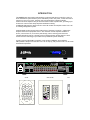
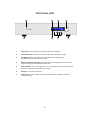
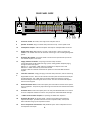
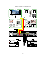
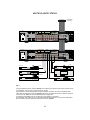
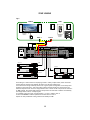
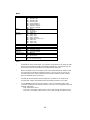
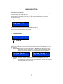
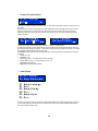
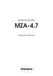
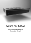
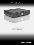
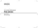
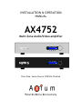
INSTALLATION & OPERATION
MANUAL
AX4752
Multi-Zone Audio/Video amplifier
12:18
Master Bed
On <Vol50> DVD
12:18
Master Bed
On <Vol50> DVD
Four Zone, Seven Source, 50W Per-Channel
Total In Home Connectivity
Congratulations!
You have purchased one of the most advanced, dedicated multi-room amplifiers on the
market. The AX4752 like other Axium products is designed to maximize control, simplify
functionality, & expedite installation. Axium products are built to the highest standards of
quality and reliability.
To view Axium’s product line of multi-room amplifiers, controllers, & accessories please
visit the Website at www.axium.co.nz
Table Of Contents
INTRODUCTION ………………………………………………………………….………………1
FEATURES……………………………………………………………………………………………2
INSTALLATION GUIDE….…………………………………………………………….……….4
FRONT PANEL GUIDE……...………………………………………………………….……..5
REAR PANEL GUIDE…………..…………………………….………………………….………6
TYPICAL SYSTEM CONFIGURATION …………………………………………….………7
CONTROLLER TERMINATION……………………………………………………………….9
ADVANCED IR CONTROL……………………………………………………………………..10
MULTIPLE AX4752 STACKS………………………………………………………………….11
ZONE LINKING………………………………………………………………………………………12
AUTOMATION……………………………………………………………………………………….13
RS232 PROTOCOL………………………………………………………………………………..14
MENU NAVIGATION……………………………………………………………………………….17
PROGRAMMING USING AMC………………………………………………………………….20
SPECIFICATIONS…………………………………………………………………………………..26
INTRODUCTION
The AX4752 multi-zone audio/video amplifier combined with Axium controllers, and/or a
home automation system enables you to individually control the power, volume and source
selection in up to four rooms, with four Sub-zone preamplifier outputs available.
Axium multi-zone amplifiers may be interconnected via the expansion bus, providing up to
32 zones of control which vastly simplifies installation cabling.
An RS232 & USB interface may be used to control & monitor the amplifier either from a PC
or building management system.
Axium Keypads are IR Learning and include a host of features to simplify / enhance the
amplifier and source equipment control. Such features include amplifier feedback of
Power, source select etc, IR receiver pass through, macro and long press functions.
The IRFX Infra-Red receiver is plasma proof & sunlight tolerant utilizing Axium’s ‘Datastream filtered’ technology to provide the best possible IR system reliability.
A utility program called AMC is available on the product CDROM or Axium website.
AMC provides a simple user interface from a PC or Laptop, and provides control of all Axium
networked components.
12:18
Master Bed
On <Vol50> DVD
230 - 240VAC 50 - 60Hz
500VA
Fuse = 2.5A Slow Blow
L
R
L
ZONE1
R
ZONE2
Z1
Z2
RISQUE DE CHOC
ELECTRIQUE NE PAS
OUVRIR
Z3
Z4
RS232 Serial interface
WARNING
CAUTION ATTENTION
RISK OF ELECTRIC
SHOCK DO NOT
OPEN
Expansion Bus Output
TO REDUCE THE RISK OF FIRE OR ELECTRIC
SHOCK DO NOT EXPOSE THIS UNIT
TO RAIN OR MOISTURE
SAT
DVD
VID
AUX
CD
TA
TU
0V PG 1
UT
AX4752i
Multi-Room amplifier
Made in New Zealand
Audio Engineering Ltd
FUSE
Z 107
L
+12V
L
L
2 3 4 #
AMP ON
C
D
IR outputs
IR2
Data 12V IR2 0V
IR1
Data 12V IR1 0V
IR1+IR2
R
L
POWER
R
L
ZONE3
R
ZONE4
R
R
PRE OUTPUTS
Expansion Bus Input
INPUT SOURCES
AX-KPD
IRFX
KRXm and KRXs
CD
Tuner
Cable
DMS
Aux
DVD
CD
MCD
TU
AUX
VOL
1
2
3
4
5
6
7
8
9
-/--
0
AV
SET
DMS
DVD
Skip
MUTE
1
2
3
4
5
6
7
8
9
0
+
-
Axium
- VOL
Axium
VOL +
DISC
SELECT
GROUP
RANDOM
FEATURES
Mulit-Zone , Multi-Source, Video Switching
The AX4752 has four separate preamplifiers and amplifiers, providing 4 zones of independent yet
integrated control.
There are seven stereo sources (SAT, DVD, VID, AUX, CD, Tape & Tuner) and an eighth mono source
(Utility) typically used for paging applications.
Each zone has an eight source composite video switcher, so screen’s in four different rooms may
display any of the eight sources (SAT, DVD, VID, AUX, CD, Tape, Tuner & Utility)
Preamplifiers and outputs
Each zone has bass, treble, balance and loudness control. These are accessed either from the front
panel or AMC program.
The preamplifier output volume may be independent of the amplifier volume, or made to track the
amplifier with an adjustable offset (± 20dB). The tracking feature is great for passive subwoofer
control, while the independent volume feature is useful for limited control in close-coupled rooms.
A useful protection feature is ‘Maximum volume limiting’. This limits the maximum volume of either
the amplifier or preamplifier.
Amplifier Power, Protection, and Clipping indicators
50 Watts RMS per channel into 8 ohms, capable of driving into 4 ohms.
The amplifiers are protected against short-term output shorts.
There are three progressive levels of thermal protection:
1) An internal fan is turned on to aid cooling.
2) The amplifier volume is reduced 20dB.
3) The amplifiers are shutdown until the temperature reduces below the first level.
Care should be taken to ensure adequate ventilation – see “installation guide”
The front panel zone indicators will flash red when the zone amplifiers are overdriven into clipping.
USB, RS232 & IR Control
The AX4752 may be controlled and monitored via either the front Panel USB or rear panel RS232
serial interface.
In multi amplifier installations where the amplifiers are interconnected using an expansion bus cable,
only one USB or RS232 connection is required to control the stack of amplifiers.
An AX4752 may receive IR directly from the front panel receiver or via the two ‘Controller interface’
connections.
There are zone specific IR commands and also a set of global IR commands.
The commands are: ON, OFF, Standby (toggling), Mute, Amp Volume Up, Amp Volume Down, Pre
Volume Up, Pre Volume Down, SAT, DVD, VID, AUX, CD, TA, TU, UTILITY, On with Source specific
commands.
The Global commands also include; PRESET1 – PRESET 6, Alarm Enable, Alarm OFF, & 5 minute Sleep.
Real time clock
The AX4752 is equipped with a real time clock.
The amplifier may be set up to function as an alarm clock, so that at 6.30am in the morning 5 days a
week, the master bedroom zone could be made to turn on, select tuner, and go to a specific volume.
Another application of the clock is temperature and event logging, providing a history of the amplifier
environment which aids servicing.
The clock continues to operate typically > 48 hours without power – more than enough to keep the
time current during lengthy power outages.
IR Emitter Ports
There are 4 Buffered IR emitter Ports.
Two IR ports have routing, and are linked to their respective ‘Controller Interface’ ports. These ports
control zone specific source components.
Two IR ports are the sum of both IR sources; these control the all zone source components.
2
Presets & Paging
There are six amplifier presets, and a ‘page preset’.
Presets 1 - 6 are momentary and cause the amplifier to go to a predetermined setup, i.e. standby,
volume & source selection. The presets may also be programmed with event scheduling, and are used
by the alarm clock feature.
The ‘page preset’ mode is for paging applications and is invoked by a contact closure between the
‘0V’ and the ‘PG’ terminals. When the contact closure is released the amplifier zones return to their
previous states.
Zone Linking
A zone may be programmed to link one other zone. Zone linking ties the source selection together. It
may also tie the volume, and standby. This is useful for closely coupled audio areas where it is
advantageous to have different volume control but the same source, or the same volume with
separate standby control. Zone linking is setup either via the front panel user interface or by the AMC
program.
32 Zones
There are 32 zones of possible control. On an AX4752 each zone must be different, however in a
multiple amplifier stack same zone amplifiers are possible – they simply mimic every parameter.
Expansion Bus
Data, IR, Amp-On & audio sources are interconnected via the expansion bus.
The expansion bus feature vastly simplifies the installation cabling of an Axium amplifier stack.
One amplifier is connected to another using a 34-way ribbon cable. Connections are made from the
output of the first amplifier to the input of the second etc.
All audio sources must be connected to the first amplifier.
Note: Video signals are not passed through the expansion bus.
Amplifier ON Status - “Amp-On”
Each zone has front panel ON status indication, and +12VDC outputs on the rear panel connector. (1,
2, 3, 4 & #) The # ‘AMP ON’ output is a logic ‘And’ output, i.e. if any of the zones are ON then the
output is +12V. This is useful for driving a relay that connects AC power to source equipment. The
‘AMP ON’ output’s are protected against shorts. The ‘AMP ON’ output default to tracking the
preamplifier ON status but may be set to track the amplifier ON status. This is set via the AMC
program.
Axium Bus
Axium Bus provides inter-amplifier control & amplifier status for the old style KRX membrane
Keypads.
The Bus is short protected. (Terminals C & D)
Power failure Restoration
After an AC power outage the AX4752 restores it’s settings to the pre-interrupted state. All internal
settings are stored in non-volatile memory, except the clock that runs for at least 48 hours on stored
power.
Restore factory defaults
Push and holding down the rotary encoder for > 10 seconds takes you to the setup menu, select
restore factory defaults, and press again. The amplifier will be reset to factory defaults, and the
memory cleared.
Firmware upgradeable
The AX4752 may be updated with the latest operational firmware, using Axium ‘Uploader 2’ program.
The ability to enhance the functionality of installed Axium product’s provides a degree of future
proofing, and flexibility.
3
INSTALLATION GUIDE
UNPACKING
Immediately upon receiving your AX4752 inspect the carton for evidence of mishandling
during shipment. Then carefully unpack the unit and inspect for damage.
Please save the shipping carton and all inner packing materials in the event that the
AX4752 needs to be shipped for service or moved to a new location.
Should you discover that the AX4752 has been damaged during shipping please contact your
dealer immediately.
PRECAUTIONS
1)
Never expose the unit to moisture.
2)
Avoid restricting the airflow around the AX4752. Good airflow is necessary to help
ensure proper operation. Not only should you provide enough free space around the
unit, but also ensure that air can flow freely and escape from the amplifier
surroundings. Failure to do so may cause thermal shutdown of the unit, or
intermittent channel cutout and reduced life expectancy. A thermal temperature
log is kept.
3)
Under no circumstances should the speaker output terminals of the unit be short
circuited, or connected to another output.
4)
Avoid plugging the RS232 cable into the unit while power is connected.
5)
Never short the controller interface or 9 way controller terminals.
6)
Avoid installing the AX4752 in positions where the front panel is exposed to direct
sun light. This may intermittently slow down the response of the unit.
7)
Never connect more than four Axium controllers to the unit’s +12Vdc power supply
terminals. The supply is internally fused and will open circuit (self-resetting).
8)
Never connect the AX4752’s +12Vdc power supply to an external power supply or
other Axium amplifier’s +12Vdc output.
4
FRONT PANEL GUIDE
1
2
3
4
12:18
Master Bed
On <Vol50> DVD
7
6
5
1
Front Panel: Solid Aluminum front Panel with Engraved Axium Logo.
2
Infra-Red Receiver: Receiver for front panel IR control – Not IR pass through!
3
LCD display: Back lit LCD display for menu guided control & programming.
7
The display is dimmed when all zones are OFF.
4
Rotary Encoder & Push Select: The display menus are navigated and selections made
using left and right rotation and pushes on the knob.
5
Zone Indicators: From Left to right zone 1 – 4. The indicators are blue when ON, and flash
red when the amplifiers are overdriven into clipping.
6
USB port: Front panel programming.
7
Chassis Feet: Set high enough to provide unrestricted airflow through the chassis for
convection cooling.
5
REAR PANEL GUIDE
8
9
10
230 - 240VAC 50 - 60Hz
500VA
Fuse = 2.5A Slow Blow
R
ZONE1
L
R
ZONE2
Z1
Z2
RISQUE DE CHOC
ELECTRIQUE NE PAS
OUVRIR
Z3
Z4
12
RS232 Serial interface
WARNING
CAUTION ATTENTION
RISK OF ELECTRIC
SHOCK DO NOT
OPEN
L
FUSE
11
13
Expansion Bus Output
TO REDUCE THE RISK OF FIRE OR ELECTRIC
SHOCK DO NOT EXPOSE THIS UNIT
TO RAIN OR MOISTURE
SAT
DVD
VID
AUX
CD
TA
TU
0V PG 1
UT
AX4752i
Multi-Room amplifier
Made in New Zealand
Audio Engineering Ltd
Z 107
L
L
L
2 3 4 #
AMP ON
C
D
IR outputs
+12V
IR2
Data 12V IR2 0V
IR1
Data 12V IR1 0V
IR1+IR2
R
POWER
L
R
ZONE3
L
R
ZONE4
R
R
PRE OUTPUTS
INPUT SOURCES
Expansion Bus Input
19
18
17
8
AC Power Socket: IEC socket, with integral fuse and power switch.
9
Speaker Terminals: Plug in terminal clamp connectors accept 1.5mm² speaker wires
10
Preamplifier Outputs: Audio and composite video outputs. Gold plated RCA connectors.
11
RS232 Comm Port: DB9 connector. The port is used to setup, control or monitor the
16
AX4752. A null modem cable must be used when connecting to a PC or building management
system.
12
Expansion Bus Output: 34 way IDC header. Connects to the expansion bus input of the
next AX4752i amplifier in the stack.
13
Paging & Status Terminals: 9 way Plug in terminal clamp connector.
A short between PG and 0V invokes the ‘Page’ preset, making possible telephone paging
through the multi-zone system.
AMP-ON 1, 2, 3, 4 provides +12VDC when the preamplifier or amplifier zone is ON.
AMP-ON # is +12VDC whenever any of the zones are ON.
Terminals C & D are Axium Bus connections for operation of the Axium KRX membrane
keypads.
14
Controller Interface: 4 way green plug in terminal clamp connectors, used for connecting
to
Keypads & IR receivers. There are two controller interface ports each linked with an IR port
providing IR routing. The +12VDC output is internally fused (self-resetting), and has a
maximum loading of 4 Axium keypad’s or IR receivers. The ‘Data’ terminal sends amplifier
status to Axium keypads.
15
Routed IR Emitter Ports: 3.5mm mono phone jacks. IR1 & IR2 are used to control specific
source components. The ports only output IR strings received from their associated controller
interface.
16
IR Emitter Ports: 3.5mm mono phone jacks. The two jacks labeled IR1+IR2 are for control
of source components common to all zones. They output the combined IR1 & IR2 IR strings.
17
+12VDC Center Positive Outputs: For powering the AX07S slave amplifiers.
18
Expansion Bus Input: 34 way IDC header. Connects from another Axium amplifiers
expansion bus output – provides connection of source component audio, control, & IR.
Note: Video does not go up the expansion bus lead.
19
Source Component Connections: Gold plated RCA jacks. Source component line level
and composite video inputs.
6
15
14
TYPICAL SYSTEM CONFIGURATION
Lounge
Study
CD
MCD
TU
AUX
VOL
DMS
DVD
MUTE
+
-
Axium
IRFX Receiver
Controller 1
interface
Zone 1
Zone 2
Gym
Bedroom & Ensuite
CD
MCD
TU
AUX
DMS
DVD
Keypad
Controller 1
interface
VOL
MUTE
1
2
3
4
5
6
7
8
9
-/--
0
AV
CD
MCD
TU
AUX
DMS
DVD
VOL
MUTE
+
+
-
DISC
SELECT
GROUP
RANDOM
-
Axium
Axium
Keypad
Controller 1
interface
AMP
Zone 3
230 - 240VAC 50 - 60Hz
500VA
Fuse = 2.5A Slow Blow
R
ZONE1
FUSE
Zone 4
CAUTION ATTENTION
RISK OF ELECTRIC
SHOCK DO NOT
OPEN
L
L
ACTIVE
SUB
Keypad
Controller 2
interface
R
ZONE2
Z1
Z2
RISQUE DE CHOC
ELECTRIQUE NE PAS
OUVRIR
Z3
Z4
RS232 Serial interface
WARNING
Expansion Bus Output
TO REDUCE THE RISK OF FIRE OR ELECTRIC
SHOCK DO NOT EXPOSE THIS UNIT
TO RAIN OR MOISTURE
SAT
DVD
VID
AUX
CD
TA
TU
0V PG 1
UT
AX4752i
Multi-Room amplifier
Made in New Zealand
Audio Engineering Ltd
Z 107
L
L
L
R
R
R
+12V
2 3 4 #
AMP ON
C
D
IR outputs
IR2
Data 12V IR2 0V
IR1
Data 12V IR1 0V
IR1+IR2
POWER
SAT receiver
L
R
ZONE3
L
R
ZONE4
PRE OUTPUTS
Expansion Bus Input
INPUT SOURCES
Tuner
To IR1
To IR2
CD changer
DVD Player
VCR Player
To IR1+ IR2
DMS player
Fig 1
7
To IR1 + IR2
Typical System Configuration:
Fig 1 depicts a typical configuration, where the AX4752 is providing audio into four listening zones.
Each zone consists of a room with a pair of speakers, and a suitable controller. Additionally a zone
may require TV’s or screens. In Fig 1 three such screens are shown in the Lounge, Gym, and Bedroom.
Each zone may be listening / watching any of the 6 connected sources: Satellite Receiver, DVD,
Video, Digital Music Server, CD Changer, or Tuner.
Controllers:
Each zone has specific control requirements.
Zone 1 - The Lounge - The ideal control in the lounge environment is from the sofa or lounge suite.
The IRFX is a Plasma proof IR receiver, and is most suitable for IR reception from a learning
remote control.
Zone 2 - The Study - This is a listening environment where remote controls are not welcome on the
busy
desk. The best solution is a wall-mounted keypad. An Axium keypad displays amplifier power
& source selection status. The keypad learns the source equipment IR commands, and relays
these to the equipment via the AX4752.
Zone 3 - The Gym - A KRXm & the numeric KRXs keypad are used to provide additional access to the
CD
changer, and SAT receiver. In addition the Keypads IR receiver is enabled so that changes can
be made using a remote while working out.
Zone 4 - The Bedroom - The KRXm keypad is situated by the bedrooms adjoining ensuite and
provides
control in that environment. The bedroom control is via the keypad’s IR receiver and a
learning remote control.
Source control IR emitters are plugged into the IR out ports.
There are two IR ports which combine both the controller inputs (IR1 + IR2) These outputs control
sources required in all zones i.e. DVD, VCR, CD & DMS. Each controller interface has an associated IR
Out port that routes IR only to that output. In Fig1 the SAT emitter is plugged into IR out port IR1,
which means the zone 1, 3 & 4 controllers may control the SAT source. The Tuner emitter is plugged
into IR Out port IR2, so only the zone 2 controller may control the Tuner.
Source Components:
The AX4752 has RCA audio inputs for connecting seven stereo source components & one mono source.
The Fig 1 configuration has only six of the possible eight sources populated.
Each zone may select from any of the connected sources. Someone in the lounge may be listening and
viewing the DVD source, while another in the study may be listening to music from the Digital Music
server.
All four zones may even select the same source, in such circumstances there is a possibility that all
four zones may be trying to control that source - this is not always desirable - so a system should be
well planned and where appropriate additional source equipment installed.
Speakers:
Speakers in each zone are connected to the AX4752 by ‘Home-Run’ speaker cables.
Each zone has a maximum loading of 4 ohms.
Fig 1 depicts a powered subwoofer in the study. The subwoofer is driven by the zone 2 preamplifier,
and is set to track the zone 2 amplifier volume. The subwoofer volume or offset can be adjusted for
correct tonal balance.
Fig 1 additionally depicts a pair of speakers in the bedroom. These are the associated bedroom
ensuite speakers and are driven by a low powered slave amplifier. The zone 4 preamplifier has been
set to ‘Independent’ mode and connects to the low powered slave amplifier.
Independent mode is where the preamplifier volume may be different from the amplifier volume
(within a range of 55dB), it also has independent Standby and Muting.
Suitable cable for Line level audio is RG59.
Video Outputs:
The composite video outputs are suitable for driving ONE composite video display device. To avoid
signal degradation, home runs of Quad screen RG6 should be less than 100meters.
8
CONTROLLER TERMINATION
0V PG 1
2 3 4 #
AMP ON
C
D
IR outputs
IR1+IR2
IR2
Data 12V IR2 0V
IR1+IR2
IR1
Data 12V IR1 0V
Data 12V IR 0V
CAT5E cable used to
connect controllers to
AX4752
Fig 2
The recommended wiring and colour scheme is shown in Fig 2. Use home runs of Cat5E cable.
The maximum recommended cable distance from the controller to AX4752 is 200m.
When +12VDC is applied to the IRFX ‘ON’ terminal the receiver module’s ‘Ampon’ indicator
illuminates. The ON terminal should be terminated to the amplifier zone’s ‘Ampon’ output not to the
controller interface ports ‘Data’ terminal.
9
ADVANCED IR CONTROL
RS232 Serial interface
TA
TU
Expansion Bus Output
0V PG 1
UT
AX4752i
Multi-Room amplifier
Made in New Zealand
Audio Engineering Ltd
+12V
2 3 4 #
AMP ON
C
D
IR outputs
L
IR2
Data 12V IR2 0V
IR1
Data 12V IR1 0V
IR1+IR2
R
Expansion Bus Input
CD changer
SAT 2
Tuner 2
SAT 1
Tuner 1
Fig 3
IR routing - discussed in ‘Typical System Configuration’ - is used to address specific centrally located
source components.
When several same brand and model source components are required in an installation, steps must be
taken to isolate the radiated IR from interfering with their discrete operation. This may be achieved
either by installing them in different cupboards or by using black IR blocking foam tape over the IR
emitters. The IR blocking foam tape is the preferred solution, since cupboard doors are often left
open.
Fig 3 shows a typical installation where several SAT receivers and tuners are required.
The dashed lines enclosing the source components represent IR isolation.
The second identical sources may be plugged into unpopulated AX4752 inputs, i.e. Tape, and Aux.
Axium controllers and sources may be re-labeled to identify their selection location.
Axium also offers an Emitter Expander ‘EX4’. This device simply provides connection for up to four
single or Dual IR emitters, and may be wired in parallel with the controller interface.
10
MULTIPLE AX4752 STACKS
To next amplifier
in the Stack
230 - 240VAC 50 - 60Hz
500VA
Fuse = 2.5A Slow Blow
R
ZONE1
FUSE
L
R
ZONE2
Z1
Z2
RISQUE DE CHOC
ELECTRIQUE NE PAS
OUVRIR
Z3
Z4
RS232 Serial interface
WARNING
CAUTION ATTENTION
RISK OF ELECTRIC
SHOCK DO NOT
OPEN
L
Expansion
ExpansionBus
BusOutput
Output
TO REDUCE THE RISK OF FIRE OR ELECTRIC
SHOCK DO NOT EXPOSE THIS UNIT
TO RAIN OR MOISTURE
SAT
DVD
VID
AUX
CD
TA
TU
0V PG 1
UT
AX4752i
Multi-Room amplifier
Made in New Zealand
Audio Engineering Ltd
+12V
Z 107
L
L
L
R
R
R
2 3 4 #
AMP ON
C
D
IR outputs
IR2
Data 12V IR2 0V
IR1
Data 12V IR1 0V
IR1+IR2
POWER
L
R
ZONE3
L
R
PRE OUTPUTS
ZONE4
RISK OF ELECTRIC
SHOCK DO NOT
OPEN
L
R
ZONE1
FUSE
L
R
ZONE2
Z1
Z2
RISQUE DE CHOC
ELECTRIQUE NE PAS
OUVRIR
Z3
Z4
RS232 Serial interface
WARNING
CAUTION ATTENTION
230 - 240VAC 50 - 60Hz
500VA
Fuse = 2.5A Slow Blow
Expansion
ExpansionBus
BusInput
Input
INPUT SOURCES
Expansion
Expansion Bus
Bus Output
Output
TO REDUCE THE RISK OF FIRE OR ELECTRIC
SHOCK DO NOT EXPOSE THIS UNIT
TO RAIN OR MOISTURE
SAT
DVD
VID
AUX
CD
TA
TU
0V PG 1
UT
AX4752i
Multi-Room amplifier
Made in New Zealand
Audio Engineering Ltd
Z 107
L
L
L
R
R
+12V
2 3 4 #
AMP ON
C
D
IR outputs
IR2
Data 12V IR2 0V
IR1
Data 12V IR1 0V
IR1+IR2
R
POWER
SAT receiver
L
R
ZONE3
L
R
ZONE4
PRE OUTPUTS
Expansion Bus Input
INPUT SOURCES
Tuner
To IR1
To IR2
CD changer
DVD Player
VCR Player
To IR1+ IR2
DMS player
To IR1 + IR2
Fig 4
In large installations where multiple AX4752’s are required, the expansion bus may be used to convey
inter-amplifier control, source component Audio, and IR.
Fig 4 shows inter-connected amplifiers using an expansion bus lead. The source component audio
inputs must be plugged into the first AX4752, where they are buffered and sent to the next amplifier
in the stack. The maximum recommended expansion is eight units.
If connecting serial RS232 only one connection to any amplifier is necessary.
The composite video inputs are not conveyed through the expansion bus, so an external video buffer
must be used to split the composite video sources to each AX4752.
11
ZONE LINKING
Fig 5
LOUNGE
STUDY
CD
MCD
TU
AUX
DMS
DVD
VOL
MUTE
+
-
Axium
IRFX Receiver
Controller 1
interface
Zone 1
230 - 240VAC 50 - 60Hz
500VA
Fuse = 2.5A Slow Blow
R
ZONE1
FUSE
Zone 2
L
R
ZONE2
Z1
Z2
RISQUE DE CHOC
ELECTRIQUE NE PAS
OUVRIR
Z3
Z4
RS232 Serial interface
WARNING
CAUTION ATTENTION
RISK OF ELECTRIC
SHOCK DO NOT
OPEN
L
ACTIVE
SUB
Keypad
Controller 1
interface
Expansion Bus Output
TO REDUCE THE RISK OF FIRE OR ELECTRIC
SHOCK DO NOT EXPOSE THIS UNIT
TO RAIN OR MOISTURE
SAT
DVD
VID
AUX
CD
TA
TU
0V PG 1
UT
AX4752i
Multi-Room amplifier
Made in New Zealand
Audio Engineering Ltd
Z 107
L
L
L
R
R
R
+12V
2 3 4 #
AMP ON
C
D
IR outputs
IR2
Data 12V IR2 0V
IR1
Data 12V IR1 0V
IR1+IR2
POWER
SAT receiver
L
R
ZONE3
L
R
ZONE4
PRE OUTPUTS
Expansion Bus Input
INPUT SOURCES
To IR1
CD changer
DVD Player
VCR Player
To IR1+ IR2
DMS player
To IR1 + IR2
Zone linking is a useful feature for simplifying control in closely coupled rooms, where the rooms
require different volume levels and ON /Off status, yet the same audio source.
If for instance the Lounge and Study zones in the ‘Typical System Configuration’ were always used
together on the same source, then zone linking could be used to simplify the control of the two
otherwise separate zones. Zone 2 is simply linked to zone 1 either via the front panel user interface
or AMC program. Once linked both zones will always select the same source whether controlled by
the lounge remote control, or study keypad.
It is possible to only link a pair of zones together, i.e. zone 1 linked to zone 2.
On the same AX4752 it would be possible to also link zone 3 to zone 4.
Options are also provided for Linking volume &/or standby via AMC.
12
AUTOMATION
Axium
Axium
230 - 240VAC 50 - 60Hz
500VA
Fuse = 2.5A Slow Blow
R
ZONE1
FUSE
L
R
ZONE2
Z1
Z2
RISQUE DE CHOC
ELECTRIQUE NE PAS
OUVRIR
Z3
Z4
RS232 Serial interface
WARNING
CAUTION ATTENTION
RISK OF ELECTRIC
SHOCK DO NOT
OPEN
L
Expansion Bus Output
TO REDUCE THE RISK OF FIRE OR ELECTRIC
SHOCK DO NOT EXPOSE THIS UNIT
TO RAIN OR MOISTURE
SAT
DVD
VID
AUX
CD
TA
TU
0V PG 1
UT
AX4752i
Multi-Room amplifier
Made in New Zealand
Audio Engineering Ltd
Z 107
L
L
L
R
R
R
+12V
2 3 4 #
AMP ON
C
D
IR outputs
IR2
Data 12V IR2 0V
IR1
Data 12V IR1 0V
IR1+IR2
L
POWER
R
ZONE3
L
R
ZONE4
PRE OUTPUTS
INPUT SOURCES
Expansion Bus Input
Contact closure
required when
Paging
DMS player
CD changer
Tuner
Fig 6
Any AX4752 parameter is controllable using the serial RS232 interface. The RS232 protocol is outlined
in the following section, and encompasses both the amplifier and connected keypads. The interface is
bi-directional, allowing the amplifier and network to be monitored.
The RS232 port connection must be made using a ‘Null Modem’ cable, where pin’s 2 & 3 are swapped
at one connector.
Fig 6 shows a typical touch panel controller providing the user interface to an AX4752. The controller
has it’s own operating system that is programmed to handle the Axium RS232 protocol. An automation
system is not restricted to touch panels, it may be an extension of a home lighting, security, building
management, or other specialized home automation system.
The ‘Page Preset’ is a special preset that is invoked whenever there is a contact closure across the
‘PG’ and 0V terminals. Each zone on the AX4752 may be set to a specific input (utility) and at
specific volumes (depends on room & application). When the contact closure is opened the AX4752
returns to its previous states. The ‘Page Preset’ is useful for telephone paging, door & gate phone
paging, or doorbell applications.
Axium also offers a six-channel relay driver – REL6 – which may be encoded for up to 16 Zones of IR
control. Typical REL6 applications are the control of curtains, screens, fan / fan speed, lights or
other simple On / Off applications that require IR remote control.
13
RS232 PROTOCOL
The RS232 Asynchronous serial port provides data acquisition and control of Axium networks by a
home automation system, or PC.
The lead must be ‘Null modem’ : 9 pin female ‘D’ connectors at both ends (pin connections 2 and 3
swapped at one end) Only RX , TX & 0V (pin 5) are used.
Baud Rate = 9600 , Characters are all ASCII.
Command Structure: <command><zone><data>line feed.
Command
Command
01
02
03
04
05
06
07
08
09
0A
0B
0C
0D
0E
0F
10
11
12
13
14
15
16
17
18
19
1A
1B
1C
1D
21
60 – 6F
70 – 7F
Description
Standby
Mute
Source Selection
Volume
Bass
Treble
Balance
Request Axium Bus protocol version
Send All parameters
Report Error
Cause key press on Keypad
Amplifier features
Maximum Volume Limit
Preset Call
Link Zone
Unsupported IR command received
Volume Up
Volume Down
Amp source – keypad bank assignment
Request Device information
Erase Memory
Request all IR function definitions
IR function Definition
Keypad Setup
Request Keypad setup
Time
Preset Schedule
Zone Name
Preamplifier Volume Mode
Request Amp Source – Keypad assignments
User defined IR commands, no data byte
User defined IR commands, one data byte
Zone Axium amplifiers and keypads are encoded with up to 32 zones
The zone byte is used for checking if the command is applicable to the device receiving the
command and if so, for optionally selecting a “sub-device”, e.g. a bank or part of a device.
The lower 5 bits of the zone byte is 00 – 1F for zones 1 to 32. The upper 3 bits represent the
sub-device. FF means all zones and can be used for turning all amplifiers ON.
The sub-device codes for the AX4752 amplifier are as follows:
000 standard amplifier
001 page preset amplifier
010 standard preamplifier
011 page preset preamplifier
For example addressing a zone 10 preamplifier = (Binary 0101010, Hex = 2A) Send ASCII ‘2A’
14
Data
Command
Standby
Mute
Source
Selection
Volume
Bass
Treble
Balance
Amplifier
features
Volume Limit
Preset
Track Zone
Content
00 – Standby A OFF
01 – Standby A ON
02 – Standby B OFF
03 – Standby B ON
04 – Toggle standby A
05 – Toggle standby B
06 – Standby A & B OFF
07 – Standby A & B ON
00 – Mute
01 – Un-mute
02 – Toggle Mute
00 – Select CD
01 – Select Tape
02 – Select Tuner
03 – Select Auxiliary
04 – Select Mono utility input
05 – Select SAT
06 – Select DVD
07 – Select Video
00 – A0 range
F4 – 0C (-12db - +12db)
F4 – 0C (-12db - +12db)
EC – 14 (Left –20db – Right –20db)
00 – Loudness enabled
01 – Loudness disabled
00 – A0 range
00 – Standard mode
11 – Force Preset
00 – 31 zone to be tracked
FF – for no zone tracking
Notes:
•
Commands are used as notifications. If an amplifier is switched ON, it will notify the other
devices on the Axium Bus by sending the Standby command (01). Any amplifiers with the
same zone will take the notification as a command and also switch ON.
•
When a command is sent to an amplifier it will first be transmitted on the Axium bus and
then returned to the PC (Home automation system). If an error occurs an error will be
returned instead of the original command. The PC (Home automation system) needs to
ignore its command when it is returned.
•
A Standby ON command implies that the amplifier is not muted, if the amplifier was
previously OFF. A Mute command must follow the Standby command if it is muted.
•
If on an AX4752 two pairs of zones are linked i.e. zones 1 & 2 and zones 3 & 4, and a
‘Link Zone’ command is sent that links zones 2 & 3, then the receiving amplifier knows the
following implications:
Zone 3 also links to zone 2
Since zone 3 is no longer linked to zone 4, zone 4 shall no longer be linked to zone 3
Since zone 2 is no longer linked to zone 1, zone 1 shall no longer be linked to zone 2
15
Example strings:
010A01 : Standby A ON command for zone 10 amplifier
012A01 : Standby ON command for zone 10 preamplifier
060002 : +2db Treble setting on zone 0
03IF02 : Tuner source selection on zone 31
0B0311 : Volume down continuous push on zone 3 keypad
Keypad key codes
An Axium Keypad may be directed to emit its learnt IR commands via RS232 control.
This is achieved by sending a ‘Cause key press on Keypad’ command, followed by the zone, and the
Keypad key code (data).
The Keypad key code is encoded with IR string repeats. (See table below)
To terminate a continuously repeating ‘Key press’, command a 00 keypad key code must be sent.
Continuous
00
01
02
03
04
05
06
07
08
09
0A
0B
0C
0D
0E
0F
10
11
12
13
14
1
xx
21
22
23
24
25
26
27
28
29
2A
2B
2C
2D
2E
2F
30
31
32
33
34
2
xx
41
42
43
44
45
46
47
48
49
4A
4B
4C
4D
4E
4F
50
51
52
53
54
REPEATS
3
4
xx
xx
61
81
62
82
63
83
64
84
65
85
66
86
67
87
68
88
69
89
6A
8A
6B
8B
6C
8C
6D
8D
6E
8E
6E
8F
70
90
71
91
72
92
73
93
74
94
KEY
5
xx
A1
A2
A3
A4
A5
A6
A7
A8
A9
AA
AB
AC
AD
AE
AF
B0
B1
B2
B3
B4
6
xx
C1
C2
C3
C4
C5
C6
C7
C8
C9
CA
CB
CC
CD
CE
CF
D0
D1
D2
D3
D4
16
7
xx
E1
E2
E3
E4
E5
E6
E7
E8
E9
EA
EB
EC
ED
EE
EF
F0
F1
F2
F3
F4
Stops repeating the current key
Aux
Tuner
CD Bank
CD
Vol Up
Ch Up (2)
Random (1)
Play
Power
+ Track skip (0)
- Track skip (9)
Disc skip
Mute
Fast Forward (8)
Rewind (7)
Pause (6)
Vol Down
Ch Down (5)
Band (4)
Stop (3)
MENU NAVIGATION
Front Panel user interface:
The controller has a 2 line by 16 character alphanumeric display with a Rotary Encoder and integral
push button (Enter key) on the knob shaft.
The AX4752 displays a hierachial menu for accessing and controlling all amplifier functions.
The user navigates through the menu using left / right rotations and Encoder Knob pushes for
selections or escapes.
•
Firmware Display
Firmware V1
The firmware version is displayed for two seconds during ‘Power-Up’
Note: The firmware may be updated to the most recent version by using the Axium ‘Up-loader 2’
program – check with your dealer for this procedure.
•
System Settings
System Setup :
Restore defaults
Set Clock
The system settings menu is entered by pushing and holding the enter Key for > 10 seconds.
Rotating the encoder displays the next system set-up function in the list: Restore Defaults, Set Clock
or Return icon.
•
Restore Defaults : Pushing the enter key will clear the AX4752 memory deleting room names,
linked Zones, maximum volume limits, bass, treble, balance adjustments, loudness
settings, alarm clock programming, preset programming and zone assignments.
System Setup :
Set Clock
•
•
Set Clock:
minutes,
Return:
System Setup :
(13) :35 Fri
The clock is 24 Hour mode, and may be set by first adjusting the hours, then
and finally the day - Pushing the enter Key at each setting. When the day is entered
the menu escapes back to ‘Set Clock’.
When entered returns to the ‘Primary Functions’ menu
17
•
Primary Functions Menu
16:40 Lounge
Off
If the zone or room is OFF then the clock, zone or room name, power OFF and select room arrow are
displayed.
Selection bars are shown surrounding the lounges OFF power status. Rotating the knob left or right
shifts the selection bars, so that either the power status or select room arrow may be selected.
Pushing the enter Key when the power status is selected will turn the lounge amp ON and display
further functions:
16:40 Lounge
On Vol77 SAT
16:40 Lounge
On(Vol77)SAT
The volume, source selection and ‘More functions’ arrow are now displayed.
To adjust the volume move the selection bars to surround the volume status and push the enter key,
the selection bars change to brackets – rotating the encoder knob now adjusts the volume. To escape
the adjustment mode simply push the enter Key.
The AX4752 always returns to the last selected zone’s volume status after 30 seconds of inactivity.
Functions:
•
Power: On / Off
•
Volume: 0 – 99.
•
Mute: Long press (>2 seconds) when volume selected.
•
Source select: CD, TU, TA, AUX, DVD, VID, SAT, UT
•
Left arrow: Select Room
•
Right Arrow: More Functions Menu
•
Select Room
Select Room:
Z4 Amp:Bedroom
Z4 Pre:Ensuite
Z1 Amp:Lounge
Z1 Pre:
Z2 Amp:Study
Z2 Pre:
Z3 Amp:Gym
Z3 Pre:
The zone number and name (if named) are displayed. Rotating the encoder Knob displays the next in
a list of eight possible room selections. Pressing the enter key selects the displayed room and then
enters its primary function menu.
18
•
More Setup
Function
Bass: 0dB
Treble : +2dB
Balance: 0dB
Loundness : Off
Max Volume : 99
Set Zone : 4
Name : Bedroom
Link Zone : none
Function
Bass: +4dB
Treble : 0dB
Balance: 0dB
Loundness : Off
Max Volume : 65
Set Zone : 4
Name : Ensuite
Link Zone : none
Preamp Volume
Selecting the right arrow in the primary function menu accesses ‘More Setup’ functions.
The rotary encoder steps through the list of functions.
•
Bass:
± 12dB of adjustment.
•
Treble:
± 12dB of adjustment.
•
Balance:
- 20dB adjustment to the Left or Right.
•
Loudness:
ON or OFF – disabled when PRE is set to independent mode.
•
Max Volume:
May be set between the maximum of 99 and minimum of 20.
•
Set Zone:
Zone encoding 0 – 31, but not a zone occupied already on the AX4752.
•
Name:
Maximum of 10 characters, upper and lower case text.
•
Link Zone:
May be linked to any ONE zone.
•
Preamp Volume:
Only displayed if the room is a preamplifier.
When selected there are two toggling options either independent or track.
•
Return:
When entered returns to the primary functions menu.
•
Protection Display
Z1&Z2 Amps
Thermal Protect
If amplifier zones are shutdown because of temperature protection a message is displayed.
The message is cleared when the enter Key is pressed, or when the temperatures normalise.
19
PROGRAMMING USING AMC
Overview;
AMC is an amplifier setup utility program.
Full control and tracking of any Axium amplifier zone is provided.
The program runs on Win 2000, NT and XP operating systems, and communicates via either an RS232
serial or USB port.
When a PC running AMC is first attached to an AX4752 the amplifier clock is automatically set to the
PC’s current time and date.
An Axium Keypad connected to the AX4752 may also be controlled by AMC, in addition the keypad’s
programming file may be imported from AxiumIR (Keypad programming software) providing button
ID’s when the cursor is placed over button.
Main Window
AMC’s main window provides most of the user functionality required for real-time access and control
of any Axium AX4752 amplifier zone.
The file menu contains the ‘New Window’, ‘Keypad Window’, ‘View Amplifier Log’, ‘Import Keypad
File’ and ‘Exit’ commands.
•
New Window: Opens another instance of AMC’s main window. This is useful for displaying and
controlling multiple zones simultaneously.
•
Keypad Window: A keypad window is displayed, and a user can cause the selected keypad on the
Axium network to emit its stored IR strings.
•
View Amplifier Log: Displays all historical over temperature events and the date and time they
occurred
•
Import Keypad file: When a relevant ‘AxiumIR’ keypad file is imported into AMC; popup
information is displayed while the cursor is moved above the keypad’s keys.
•
Exit: Shuts down AMC.
The Option Menu contains the port assignments. The program lists the ports on the PC/ laptop.
20
Zone Select: To select the zone move the cursor over the zone tab’s down arrow and left click. A
zone
list window appears - make the selection with a left mouse click.
Placing the cursor over the zone tab’s room description displays information about the
amplifier’s device ID / serial number.
Zoned Functions:
•
Standby:
On, Off control of the amplifier or preamplifier is achieved by a left click over the
standby buttons. The blue LED and the button shading indicate ‘On’ status.
The standby buttons may be named with the room name: A name edit window is
opened by a right click over the standby button - Enter the new text.
The room name is transferred to the AX4752, and also appears in the zone tab.
•
Mute:
further
A left mouse click above the mute button mutes the amplifier or preamplifier, a
left click un-mutes it.
•
Source Selects: One of eight sources (CD, TU, TA, UT, SAT, DVD, VID & AUX) may be selected –
the
button shading indicates the selection. A source’s name may be changed with a
right click over the source select button: A name edit window appears and new text
entered.
The text appears only in the AMC’s active zone and not on the AX4752.
21
•
Volume Levels: The volume sliders may be changed either by left clicks above or below the
displayed level, or by dragging the level down using a left click and hold.
Note: If the preamplifier is in ‘Tracking’ mode then changing one volume changes
the other.
•
Maximum Volume Limit: The maximum volume limit is set firstly by identifying the slider with a
left
mouse click, then on the keyboard hold down the ‘Shift’ key and adjust the level
using the ‘Up’ and ‘Down’ keys. The limit is indicated above the slider level by a
black bar as shown above in the Kitchen’s volume slider.
•
Preamplifier Tracking / Independent Mode: The chain link button between the volume sliders is
used to toggle the preamplifier volume tracking mode. When the chain symbol is
unbroken the preamplifier volume tracks the amplifier volume. An offset between
the preamplifier and amplifier volume may be made by identifying the volume bar
to be changed with a left click, then make the change on the keyboard by holding
down the ‘Ctrl’ key and adjust the level using the ‘Up’ or ‘Down’ keys. The zone 2
Main window above illustrates this and refers to the ‘Typical System Configuration’
on page 7. In this example zone 2’s preamplifier drives an active subwoofer. The
offset adjustment balances the Subs level in the listening environment.
When the chain link button is broken, the preamplifier is in ‘Independent’ mode.
While in independent mode the preamplifier volume may be adjusted independently
from the amplifier volume with one restriction: the maximum difference between
the preamplifier and amplifier volume levels is < 68.
•
All Off:
Left mouse clicks while over the ‘All OFF’ button turns OFF all AX4752 zones.
•
Setup:
Opens the Setup Window giving access to the occasionally used functions.
•
Preset 1 – 6: Momentary Presets. These are used for creating scenes and alarm clock events
•
Preset Setup: Opens the Preset Setup Window where the alarm clock & presets are programmed.
22
Setup Window
The window provides the means to control the occasionally used functions like bass, treble, amplifier
and preamplifier balance and loudness. These are all adjusted using a left mouse click while above
the button or slider.
Note:
The preamplifier and amplifier share the same bass & treble control.
Loudness is defeated when the preamplifier is set to ‘Independent Mode’.
Any one zone may be linked to one other zone by left clicking the ‘Link Zone’ down arrow, and
making the selection from the zone list. Linked zones have the same source selection. Volume and
standby may also be linked using the ‘Link Volume’ & ‘Link Standby’ Tabs. If both volume and standby
are selected then the two zones are fully linked and completely mimic each other.
The ‘Ampon’ output’s on the AX4752 default to tracking the preamplifier ‘ON’ status. However when
in independent mode it may be useful for the ‘Ampon’ output to be assigned to the amplifier. Select
using a left click on the Amp tab.
23
Preset Setup Window
Preset Programming: Preset programming effects all zones on the AX4752. There are six momentary
preset buttons – Preset 1 - Preset 6. These presets are stored in the AX4752, and may be setup using
the AMC setup window.
Left mouse click over ‘Set up preset 1’ and change any AX4752 function i.e. On status, volume level,
source selection, even bass, treble etc. If Preset 1 is required to effect changes to the other zones on
the AX4752, then either change the main window’s zone or open other AMC main window instances
and make the required changes, then left click over the ‘Default’ selection to exit. Preset 1 is now
programmed and will be set to the programmed preset states whenever the AX4752 receives the
preset 1 IR control string, or RS232 command.
The process is the same for all other presets.
Force page preset is used to program the page preset. When selected changes made to the zone
functions and levels are programmed. To exit the ‘Force page preset’ select ‘Default’.
Whenever a contact across the PG & 0V terminal is closed the AX4752 will go to the programmed
states, and when the contact opens the amplifier reverts to its previous settings.
Alarm Clock programming: An alarm clock event may be included in a preset. It utilizes the Preset
schedule panel. As shown above the working days Monday – Friday are selected and time set @
6:15am. The preset 6 command will then be invoked at 6:15 in the morning Monday - Friday.
IR commands are available to disable the alarm clock functions. To turn the alarm clock off select
‘Setup Preset 1’ and in the Preset Schedule panel left mouse click over the ‘Clear’ button.
24
Source Control Alarm Clock programming: If a KRXm Axium keypad is connected to the AX4752,
then source control can also be included in an alarm preset.
Open a KRXm keypad Window and select the attached Keypad’s zone.
it can be made to send it’s source control commands
In the preset setup window select ‘Macro’. Using the mouse with left clicks select the Keypad
functions required; i.e. ‘CD select’, ‘1’, ‘2’, ‘Play’.
The above sequence is entered into the macro window. Exit the ‘Set up Preset 6’ by selecting
‘Default’.
The Axium System is now programmed to Select the CD source, and Play Disc 12 on the CD player @
6:15am Monday through to Friday.
25
SPECIFICATIONS
AUDIO
•
•
•
•
•
•
•
•
•
•
•
•
Preamplifier Gain (max: Vol = 99)…………………………………………….…………………………+15dB
Input Impedance ………………………………………………………………….……………………………...22KΩ
Output Power…………………………………………………………………….………50 Watts RMS @ 4 – 8Ω
Signal – Noise …………………………………………………………………………………...>92dB A weighted
THD (1VRMS input, Gv = 0dB)……………………………………………….……………………………….0.05%
Channel Separation (Gv = 0dB; f=1KHz).……………………………….……………………….…...>95dB
Frequency Response …………………………………………………………….…………30Hz to 50KHz ±3dB
Bass Control Range (fl = 40Hz)……………………………………………..…………….±12dB, 2dB steps
Treble Control Range (fh = 16KHz)……………………………………….…………….±12dB, 2dB steps
Loudness Boost (fb = 40Hz).……………………….…+16dB when Vol = 20, 0dB when Vol = 60
Balance Control Range………………………………….………………………………….-20dB in 2 dB steps
Maximum Volume Limit Range…………………………………………………………………...Vol : 20 – 99
VIDEO
•
•
•
Input /Output Impedance……………………………………….………………………………………………75Ω
Video Bandwidth……………………………………………………….…………………50Hz to 12MHz, –3dB
Cross-talk between channels…………………………………….…………………………typically > 70dB
INFRA-RED RECEIVERS
•
•
Control Receiver Modulation frequency …………………….……………………………………….38KHz
Control Receiver Range ……………………………………………….…………………….>8m ±30° off axis
GENERAL
•
•
•
•
•
•
Controller Interface +12VDC Outputs..Maximum of 4 controllers/ Output or 0.4A Load
Amp-ON Outputs (1,2,3,4 and #)………………………….…………………………+12VDC 300mA max
Power Requirements (Australasian Model) ………….………………….240V~ 50Hz 500VA max
(US, Canada Model) …………….……………….115V~ 60HZ, 500VA max
Dimensions …………….……….435mm (17”) Wide, 104mm (4”) High, 310mm (12¼”) Deep
Weight………………………….……………………………………………………………………………………… 10.8Kg
Box Dimensions…….…………525mm (20½”) Wide, 180mm (7”) High, 410mm (16”) Deep
26