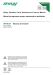
1
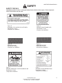
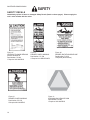
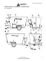
VERTI-MAXX MIXER
5000 SERIES
TRAILER TYPE OPERATORS INSTRUCTION MANUAL
READ ALL WARNINGS AND INSTRUCTIONS IN THIS MANUAL BEFORE
INSTALLING OR OPERATING THE VERTI-MAXX MIXER !
Failure to heed this may result in personal injury or death.
Catalog number #005893
5000TROPR 005893 R022504
TABLE OF CONTENTS
INTRODUCTION ............................................. 3
SAFETY
General Information ........................................ 4
Operating Safety Precautions ......................... 5
Transporting Safety Precautions ..................... 6
Safety Decals ........................................... 7-10
Safety Decal Placement ............................... 11
TRACTOR SETUP
Tractor Weight & HP Requirements ............. 12
Drawbar Attaching system ........................... 12
Hydraulic Requirements ............................... 12
MIXER SETUP
Safety Shielding ...........................................
Safety Lighting .............................................
Clevis setup .................................................
Scale setup ..................................................
Mixer Run-In .................................................
2
2
13
13
13
13
13
MIXER OPERATION
Safety .......................................................... 14
General ........................................................ 15
Step #1 - Processing ................................... 15
Step #2 - Mixing ........................................... 16
Step #3 - Unloading ...................................... 16
Step #4 - Other Mixing Recommendations ... 17
Knife Adjustments ....................................17-18
Hay Stop Adjustment ................................... 19
Options ........................................................ 20
MAINTENANCE
Inspection and adjust ................................... 21
Lubrication ...............................................22-23
PTO Driveline Setup and Adjustment ............ 24
Misc. ............................................................ 25
SPECIFICATIONS ....................................26-27
5000TROPR 005893 R022504
INTRODUCTION
THANK YOU for purchasing a Kuhn Knight VERTI-MAXX MIXER. We appreciate your business. You have
purchased one of the best built, most reliable mixers available. We strive to provide you with a rugged, durable unit
which is simple to maintain. If you have suggestions for any of our products, please let us know.
Kuhn Knight INC.
USING THIS MANUAL
This manual should be considered a permanent part of your machine, and should remain with the
machine if you sell it.
This manual has been designed to help you become familiar with your unit. A separate service parts listing is
available for a detailed parts breakdown of the unit. Before you operate your unit, be sure you understand and
follow all the operation, lubrication, and safety instructions on the following pages in this manual. These have been
written for your safety and convenience, and to keep your unit running trouble-free for many years.
MODEL AND SERIAL NUMBER INFORMATION is located on the front lower panel. This
number must be given to service personnel for parts and service questions.
ADDITIONAL MANUALS and safety decals may be obtained through your dealer,
or by writing to the address below.
Order operators manual # 005893 all trailer type models
Order service parts manual # 005894 for 5032 & 5042 & 5055
Order service parts manual # 005907 for 5073, 5085 & 50100
KUHN KNIGHT, INC.
1501 West 7th Ave., Brodhead, WI 53520
701 Cherry Ave., Greeley, CO 80632
3
3
5000TROPR 005893 R022504
SAFETY
UNDERSTAND SAFETY WORDS AND SYMBOLS
THIS SAFETY ALERT SYMBOL is used in this manual whenever personal safety is involved and means
ATTENTION! BECOME ALERT! It stresses an attitude of “HEADS UP” for safety. Read and understand
all pages in this manual that bear this safety symbol and . . . TAKE TIME TO BE CAREFUL!
The Signal Word or Message areas of all safety decals are color coded to indicate the level of hazard.
CAUTION is used to direct attention to unsafe practices, and uses the color yellow.
WARNING denotes a specific potential hazard, and uses the color yellow or orange.
DANGER denotes a most serious specific potential hazard, and uses the color red.
READ THE OPERATORS MANUAL
Any person who will be operating or maintaining this mixer should first read and understand this manual and all
safety warnings on the unit.
This instruction manual should always be available to those responsible for the operation and maintenance of this
mixer. It is the owner’s responsibility to provide this safety information to his operators and employees.
Any person who does not understand the safety and operation instructions contained in this manual should not be
considered qualified to operate this mixer.
FOLLOW SAFETY INSTRUCTIONS
Specialized procedures and instructions are required and must be adhered to when working on this equipment.
Failure to follow the instructions contained in this manual could result in severe personal injury, death, and/or
product or property damage. All applicable safety procedures such as OSHA requirements, regional and local
safety codes and requirements, safe working practices, and good judgement must be used by personnel when
operating or maintaining this equipment.
4
SAFETY
5000TROPR 005893 R022504
OPERATING SAFETY PRECAUTIONS
When the mixer is in operation it has many moving parts which could cause severe injury or death to
persons coming in contact with these parts. To help avoid serious accidents, the following guidelines
should always be followed:
1.
BE SURE ALL SAFETY SHIELDS are in place before operating, including tractor PTO driveline
shields.
2.
NEVER PUT ARMS OR FEET INSIDE unit, power chute, or discharge door opening, nor climb on or in
the mixer while it is running. NEVER allow anyone to position themselves over or near the top of
the mixer while it is running. Augers, shafts, and material can grab clothing or create pinch points
which can cause severe injury or death to the operator or bystanders. Always stop engine and remove the
PTO driveline so that the mixer cannot be accidentally turned on while inspecting, servicing, repairing, or
cleaning mixer.
3.
NEVER HAND FEED MATERIALS into mixer while it is running. Augers inside mixer may not be visible
from the loading point, and may cut or grab hands, clothing, or material being loaded, causing severe injury.
Always stop engine before hand loading materials.
4.
NEVER ATTEMPT TO RELEASE JAMMED MATERIALS OR CLEAN MATERIALS from any area of the
mixer or discharge chute without stopping engine and removing driveline first. Moving parts can be
hidden by materials, and stopped parts can start unexpectedly, causing severe injury. Always stop engine
and remove PTO driveline before attempting to remove jammed material or to clean.
5.
DO NOT ALLOW OPERATION of this unit by inexperienced and unqualified people. Keep all
unqualified people away from mixer during loading and operation. Operators of this unit must be alert
and use good judgement at all times.
OPERATOR SHOULD NOT CLIMB ON LADDER OR ANY PART OF THE MIXER WHEN LOADING,
MIXING OR DISCHARGING MATERIAL.
6.
DO NOT wear loose or floppy clothing while operating this unit. Loose clothing may become entangled
in moving parts.
7.
BE SURE the inside of the mixer is clear of any obstructions and that all shields are in place before
operating. Repair or replace any damaged or missing shielding. Exposed shafting due to missing shielding
can grab hands and clothing and cause severe injury or death.
8.
SHOULD A PROBLEM OCCUR during operation of mixer, always stop engine and remove PTO
driveline before investigating problem. If power source has not been disconnected, the mixer may start
unexpectedly, causing severe injury or death.
9.
USE CAUTION WHEN WORKING AROUND THE DISCHARGE AREA. The slide tray and/or power discharge
chutes are controlled from the tractor and could operate without warning creating pinch points which could
cause severe injury or death. Always turn off tractor engine and remove PTO driveline before working close to
the discharge area.
KUHN KNIGHT, INC.
1501 West 7th Ave., Brodhead, WI 53520
701 Cherry Ave., Greeley, CO 80632
5
5000TROPR 005893 R022504
SAFETY
TRANSPORTING SAFETY PRECAUTIONS
WHEN TRANSPORTING A LOADED MIXER, USE REDUCED SPEED AND BE SURE THE TRACTOR
HAS ADEQUATE WEIGHT AND BRAKES TO TOW AND STOP THE MIXER
• The weight of the tractor should be as follows: The tractor weight should be 2/3 or more of the loaded mixer
•
weight.
The implement should never be towed over 20 M.P.H.. See tractor setup section for more information.
• Do not allow anyone to ride on or in the VERTI-MAXX mixer.
• Do not exceed 20 M.P.H. when traveling over smooth dry areas, and reduce speed when traveling loaded and/
or over rough, soft, or wet terrain. Exercise caution on side slopes and when turning corners.
• Avoid operating the mixer when making sharp turns or crossing gullies or ditches.
• When working on slopes or inclines, travel uphill or downhill. Keep the tractor transmission in gear when
going uphill or downhill. Avoid driving on loose fill, rocks, severe inclines, ditches, and holes.
• Always park the VERTI-MAXX on level ground and block the tires.
• When transporting the VERTI-MAXX, always
LOCK CHUTE
AS SHOWN
keep the power discharge chute or slide tray
in the upright (retracted) position. For long
transport distances the power chute must be
locked in place using the chain provided.
• When towing the Mixer with a tractor on a public road, always use the tractor’s FLASHING AMBER
•
LIGHTS. If the tractor’s flashing lights or taillights are obscured from the rear by the mixer, then the Lights
included with the mixer must be used.
Whenever towing the Mixer, and especially when towing on public roads, a SAFETY TOW CHAIN with an
ultimate tensile strength equal or greater than the gross weight of the mixer should be used. See Specifications
and Tractor Setup sections for gross weights.
To attach the Safety Tow Chain to the implement, pass the end link
through the attachment bar on the side of the tongue, then pass
the hook end through the end link. The hook end should then
be pulled forward through the intermediate support (if required)
on the towing machine’s drawbar, and around the towing
machine’s attaching point, hooking back to the Safety Tow Chain
itself. If the towing machine’s attaching point is more than 9" from
the draw pin, an intermediate support, capable of withstanding one
half the required chain capacity, is required. The Safety Tow Chain
should have no more slack, when in use, than necessary to permit
proper articulation of the implement. Do not use the intermediate
support as the attaching point. When not in use, the Safety Tow
Chain should be stored to prevent damage from weather or
improper use. The Safety Tow Chain must be replaced if any one
link is broken, stretched, or otherwise damaged or deformed.
6
SAFETY DECALS
SAFETY
5000TROPR 005893 R022504
SAFETY DECALS ARE PLACED ON THIS UNIT FOR THE PROTECTION OF THE OPERATOR OR ANY
PERSON NEAR THE UNIT.
Be Sure everyone who operates the mixer understands all the information, warning, caution and danger
decals.
Keep The Decals Clean so they are readable. This applies to all caution, warning, and danger decals.
It is the OWNER’S RESPONSIBILITY to provide information for safe operation of this machine.
Replace any damaged or worn decal. Once any part of a decal becomes non-readable, it should be replaced.
The part numbers for the decals are located in the lower RH corner of the decal, and listed in this manual on the
following pages. Replacement decals may be ordered through your dealer or the address below.
When replacing decals, be sure the surface area is clean and dry, peel the backing off the decal, and apply to
the Mixer. Be sure to wipe with a clean cloth to rub out all air bubbles to assure a good seal. For best adhesion
decals should be applied in temperatures of 50° (f) or warmer.
Complete sets of decals (including information decals) can be ordered by using the following part numbers:
UNIT
5032
5042
5055
5073
5085
50100
PART NO.
175-223
174-778
174-912
174-945
174-946
174-947
KUHN KNIGHT, INC.
1501 West 7th Ave., Brodhead, WI 53520
701 Cherry Ave., Greeley, CO 80632
7
5000TROPR 005893 R022504
SAFETY DECALS
SAFETY
Immediately replace all worn or damaged Safety Decals (listed on these pages). Please supply the
unit’s serial number with the order.
Figure A
WARNING, STAY CLEAR OF POWER DRIVEN
PARTS
Part Number 170-849
2 Required: ALL MODELS
Figure C
SAFETY INSTRUCTIONS
Part Number 171-911
1 Required ALL MODELS
8
Figure B
DANGER, ROTATING AUGERS
INSIDE
Part Number 171-820
2 Required ALL MODELS
Figure D
WARNING, DO NOT OPERATE UNLESS
SHIELDS ARE IN PLACE
Part Number 171-913
1 Required ALL MODELS
SAFETY DECALS
5000TROPR 005893 R022504
SAFETY
Immediately replace all worn or damaged Safety Decals (listed on these pages). Please supply the
unit’s serial number with the order.
Figure E
WARNING, STAY CLEAR OF CHUTE AREA
Part Number 171-914
2 Required ALL MODELS
Figure G
RED REFLECTOR
Part Number 174-686
5 Required ALL MODELS
Figure F
DANGER, DO NOT HAND LOAD
Part Number 171-947
2 Required ALL MODELS
Figure H
AMBER REFLECTOR
Part Number 174-687
3 Required ALL MODELS
Figure I
DANGER, KEEP AWAY, ROTATING DRIVE LINE
Part Number 172-786
1 Required ALL MODELS
Figure J
WARNING, LIFTING INSTRUCTIONS
Part Number 172-820
1 Required ALL MODELS
KUHN KNIGHT, INC.
1501 West 7th Ave., Brodhead, WI 53520
701 Cherry Ave., Greeley, CO 80632
9
5000TROPR 005893 R022504
SAFETY DECALS
SAFETY
Immediately replace all worn or damaged Safety Decals (listed on these pages). Please supply the
unit’s serial number with the order.
Figure K
CAUTION, TO AVOID SERIOUS
INJURY OR DEATH
Part Number 173-040
1 Required ALL MODELS
Figure N
DANGER, SHIELD MISSING
Part Number 173-078
2 Required ALL MODELS
10
Figure L
DANGER, SHIELD MISSING
Part Number 171-799
1 Required ALL DRIVELINES
Figure M
DANGER, ROTATING DRIVE LINE
Part Number 171-550
1 Required (All Drivelines)
Figure O
SLOW MOVING VEHICLE SIGN
Part Number 170-893
1 Required ALL MODELS
SAFETY
5000TROPR 005893 R022504
SAFETY DECAL PLACEMENT ILLUSTRATIONS
ALL MODELS
KUHN KNIGHT, INC.
1501 West 7th Ave., Brodhead, WI 53520
701 Cherry Ave., Greeley, CO 80632
11
5000TROPR 005893 R022504
MIXER SETUP
IMPORTANT! READ BEFORE OPERATING MIXER.
IT IS THE RESPONSIBILITY OF THE OWNER TO MAKE SURE THE MIXER IS SET
UP PROPERLY. THE FOLLOWING RECOMMENDATIONS SHOULD BE HELPFUL
UNIT
5032
5042
5055
5073
5085
50100
EMPTY UNIT WT. + LOAD WT. = GROSS WT.
8,200 +______________ =______________
9,650 +______________ =______________
10,800 +______________=______________
17,000 +______________= _____________
21,500 +______________=______________
22,000 +______________=______________
TRACTOR WEIGHT AT UP TO 20 MPH
2/3 OF GROSS WT. = TRACTOR WT.
2/3 OF GROSS WT. = TRACTOR WT.
2/3 OF GROSS WT. = TRACTOR WT.
2/3 OF GROSS WT. = TRACTOR WT.
2/3 OF GROSS WT. = TRACTOR WT.
2/3 OF GROSS WT. = TRACTOR WT.
A tractor with the above recommended weight for your unit is normally adequate for towing the loaded mixer under
average conditions. Unit weights include tires & power chute.
TRACTOR PTO HORSEPOWER REQUIREMENTS
PTO horsepower requirements are based on most
normal dairy or beef rations. Horsepower requirements may vary depending on the ration or
material to be mixed.
The PTO horsepower requirements shown may not
reflect adequate tractor size for towing the mixer, refer
to tractor weight requirements for these recommendations and transporting safety precautions for additional
tractor and towing requirements.
MODEL
5032/42
5055
5073
5085
50100
PTO HORSEPOWER
65 - 90 AT 540RPM
85 -120 AT 1000RPM
130 AT 1000 RPM
140 AT 1000 RPM
150 AT 1000 RPM
DRAWBAR ATTACHING SYSTEM
Adjust tractor drawbar and/or the mixer clevis hitch so that the
mixer is approximately level. The top of the drawbar should be
8 - 12" below the tractor PTO shaft. Adjust the drawbar horizontally
so that the hitch pin hole is (14” - 16") 14” for 540 RPM 1-3/8” DIA.,
16” for 1000 RPM 1-3/8” DIA. 21 spline and 16” for 1000 RPM 1-3/4”
DIA. 20 spline behind the tractor PTO and drawbar is centered and
locked into place. Knight Manufacturing does not recommend or
authorize PTO adapters.
HYDRAULIC REQUIREMENTS
Dual hydraulic outlets are required for operating the door and the slide tray or power chute. If your tractor has
only a single set of ports, then the manual diverter or electric selector valve option should be ordered. If the power
chute is used, the tractor hydraulic system must supply a minimum of 15 GPM at 2000 PSI. On units with power
chute option, the chute hoses may be difficult to connect due to the chute weight on the lift cylinder. Lift weight off
chute cylinder to connect hoses.
12
MIXER SETUP
5000TROPR 005893 R022504
IMPORTANT! READ BEFORE OPERATING MIXER.
IT IS THE RESPONSIBILITY OF THE OWNER TO MAKE SURE THE MIXER IS SET
UP PROPERLY. THE FOLLOWING RECOMMENDATIONS SHOULD BE HELPFUL
SAFETY SHIELDING
Be sure all shielding is in place and functioning properly. Replace all damaged or missing shielding immediately see parts pages or call your dealer for replacement safety shielding part numbers.
SAFETY LIGHTING
The lighting system provided is intended for agricultural tractor transport only. If the mixer will be transported on a
public roadway, be sure the lights are in good working order. When attaching to a towing vehicle other than a
tractor, always check for proper operation, as wiring may vary.
LUBRICATION
Check to be sure that all gearcases and oil bath contain oil, and that bearings and joints have been greased
(see maintenance section)
CLEVIS SETUP
The clevis (and the clevis mount) on the front of the mixer can be adjusted for height. Mount the clevis so that the
mixer is as level as possible when connected to the tractor. Be sure that the PTO driveline does not contact the
clevis (or clevis mount) during normal operation or transport.
The clevis is adjustable vertically on all models and can be rotated 360°
to allow for maximum adjustment only on 5032/5042/5055/5073.
THE CLEVIS COULD DAMAGE PTO DRIVELINE IF
OPERATED ON UNEVEN TERRAIN WITH CLEVIS
Care should be taken in rotating for low tongue
ADJUSTED AS SHOWN.
height due to potential PTO shaft interference.
THIS SETTING IS NOT RECOMMENDED
A hitch pin with a minimum of 1 1/4” diameter
with a retainer pin is recommended.
SCALE SETUP
Connect the power cord to the mixer battery or 12V tractor connection and check the scale for proper operation
(see scale manual).
POWER CHUTE (option) ADJUSTMENT
To adjust the height of the power chute, change the length of the link chains on the
sides of the chute. For best performance, the unloading height should be set at the
lowest height possible . The discharge tip-off on the power chute should be adjusted
for correct magnet and discharge angle. Loosen the adjusting bolts and tighten at
desired tip-off angle.
MIXER RUN-IN
1. Check for proper assembly, adjustment, and lubrication. Check to see that there is adequate oil in the gearboxes and
bull gear oil bath. If unit is equipped with a discharge chute, oil the roller chains and check to be sure all bolts and
set screws are tight. Review Operating Safety Precautions and Lubrication Instructions before operating the mixer.
2. Be sure all shields are properly in place.
3. Check for and remove any foreign objects in the mixer hopper and discharge opening.
4. Check to see that the door is closed.
5. Be sure no one is inside the mixer.
6. Test run the mixer. a. Make sure mixer is empty, then start the mixer.
b. Run mixer for at least five minutes at 3/4 of rated PTO RPM.
c. If unit is equipped with power chute, run discharge for 1 hour with no load for proper motor break in.
d. Raise and lower the door and the chute or slide tray several times.
e. Disengage the mixer, turn off the tractor engine, and remove driveline.
f. Check the mixer drive components to be sure they are not abnormally hot.
If any of these items are not running as indicated, immediately repair or contact your local dealer.
Always refer to Operating Safety Precautions before operating or servicing the mixer.
KUHN KNIGHT, INC.
1501 West 7th Ave., Brodhead, WI 53520
701 Cherry Ave., Greeley, CO 80632
13
5000TROPR 005893 R022504
MIXER OPERATION
Always refer to Operating Safety Precautions and Safety Decal sections of this manual before operating
this mixer.
SAFETY
When the mixer is in operation, it has moving parts which could cause severe injury or death to persons
coming in contact with these parts. To help avoid serious accidents, the following precautions should
always be followed:
DANGER: NEVER HAND FEED MATERIALS into mixer while it is running, always stop engine and
remove ignition key before hand loading materials. Rotating augers inside mixer may not be visible from
the loading point, and may cut or grab hands, clothing, or material being loaded, causing severe injury.
DANGER: NEVER PUT HANDS, ARMS OR FEET INSIDE unit, nor climb on or in the mixer while
it is running. Never allow anyone to position themselves near the mixer or over or near the
top of the mixer while it is running. Rotating augers can grab clothing or create pinch points which
can cause severe injury or death to the operator or bystanders. Always stop engine and remove the
ignition key so that the mixer cannot be accidentally turned on while inspecting, servicing, repairing, or
cleaning.
DANGER: NEVER ATTEMPT TO RELEASE JAMMED MATERIALS OR CLEAN MATERIALS from
any area of the mixer or discharge chute without stopping engine and removing driveline first.
Moving parts and knives can be hidden by materials, and stopped parts can start unexpectedly, causing
severe injury. Always stop engine and remove ignition key before attempting to remove jammed material
or clean.
DANGER: DO NOT ALLOW OPERATION of this unit by inexperienced and unqualified people.
Keep all unqualified people away from mixer during loading and operation. Operators of this unit
must be alert and use good judgement at all times.
OPERATOR SHOULD NOT CLIMB ON LADDER OR ANY PART OF THE MIXER WHEN LOADING,
MIXING OR DISCHARGING MATERIAL.
Keep in mind the overall size of the mixer to allow clearance through doorways, make sure the
chute is in the up position and there is adequate side and top clearance through doorway.
14
MIXER OPERATION
5000TROPR 005893 R022504
Always refer to Operating Safety Precautions and Safety Decal sections of this manual before operating
this mixer.
OPERATION OF YOUR VERTI-MAXX MIXER
There are some basic concepts that must be understood to achieve top mixing performance with the Verti-Maxx.
A new machine will need an initial run-in period to polish the augers and mixer sides to achieve correct material
movement inside the mixer. Until the unit is polished inside, one may experience material spillage, dead spots, or
increased horsepower requirements. The load size may need to be reduced until the unit is polished inside.
Mixing a ration in a vertical mixer generally involves three steps; processing, mixing, and unloading. The sequence
and timing of these steps is very important, and is different for every operator because of variations in materials and
conditions. There is some experimentation that must be done to work out the best equipment, sequence, and
timing for your particular operation. Following are some general suggestions to achieve good results.
Step #1 - Processing
Materials
Some feed materials will first need to be processed alone in the Verti-Maxx before they can be efficiently mixed
with other feedstuffs in the Verti-Maxx mixer. These materials include;
A. Large square or round bales of alfalfa*
B. Large square or round bales of high moisture “Baleage”*
C. Large square or round bales of long mixed grasses, wheat or oat hay and crop residue bales (straw or
soybean stubble)*
D. Very light and bulky feedstuffs*
* Always remove twine from bales before loading into the mixer.
Mixer Setup
A. Be sure that mixer is sitting level front to back and side to side.
This will ensure a level and even mix of feed.
B. Be sure tractor is sitting straight in line with the mixer.
This will prevent premature wear to the driveline and gearboxes.
C. Completely close mixer door.
D. Set Hay Stops according to instructions in Maintenance section.
Loading
A. With the tractor running at approximately 3/4 of rated PTO speed, load baled hay into center of mixer.
B. Allow mixer enough time to process bale before adding other ingredients (4 to 10 minutes) If you need
to inspect progress of the processing /mixing, always shut off mixer and tractor before climbing the
ladder to inspect the load.
C. Processing of long stem forages will continue as other materials are added and mixed. Be careful not
to over process these materials before adding other ingredients.
Adjustments
A. When processing materials, there may be spillage over the side of the mixer. Following are some
steps to reduce this;
1. Reduce load size
2. Reduce tractor/mixer RPM
3. Be sure mixer is level
4. Be sure augers and hoppers are polished so feed moves well inside mixer.
5. Back off “Hay Stops” to a less aggressive or neutral position.
6. Reset knives to a less aggressive setting.
7. If spillage still occurs, the optional side extensions for the mixer may be needed.
KUHN KNIGHT, INC.
1501 West 7th Ave., Brodhead, WI 53520
701 Cherry Ave., Greeley, CO 80632
15
5000TROPR 005893 R022504
MIXER OPERATION
Always refer to Operating Safety Precautions and Safety Decal sections of this manual before operating
this mixer.
Step #2 - Mixing
Materials
The Verti-Maxx is designed to mix a wide variety of feedstuffs efficiently and quickly. After the long stem forages
are coarsely cut in the processing step, other materials such as silage, grains, haylage, and commodities can be
added and mixed.
Loading Sequence
With mixer running at approximately 3/4 of rated PTO RPM, and the long stem material processed to a desirable
length, the loading of remaining ingredients can begin. The sequence of loading materials will depend on the loading
methods and their location relative to the mixer, but a typical loading sequence would be;
1. Load haylage and corn silage
2. Load minerals, proteins, and other small quantity ingredients.
(Note- in some cases it may be preferable to load these between the silage’s if possible)
3. Load grains, wet and dry commodities, etc.
4. Load all liquid fats, water, and other liquids. Always load liquids at the center of the mixing chamber.
Note: Never load long stem bales last. They will not be processed or mixed into the ration,
and may cause unloading or spillage difficulties. Processing of long stem forages will
continue as other materials are added and mixed. Be careful not to over process these
materials before adding other ingredients.
Load all ingredients as quickly as possible, and allow a final mix time of 3 to 7 minutes, or whenever the load looks
consistently mixed.
Adjustments
A few loads will need to be tried to establish the best loading sequence, PTO RPM, mix time, and hay stop
position for your particular situation. Adjustments may need to be made if you see the following;
1. Spillage - refer to the adjustments listed in the processing steps.
2. High horsepower
a. Reduce load size
b. Be sure mixer sides and augers are “polished” to insure correct feed movement inside mixer.
c. Back off “Hay Stops” to a less aggressive or neutral position see Hay Stop Adjustment section
d. Modify the knife setting quantity or placement, see Inspection and Adjustment section
e. Add optional short knives if available
3. Forage is cut too short
a. Reduce the initial processing time
b. Reduce the aggressiveness of the hay stops, see Hay Stop Adjustment section
c. Reduce the total loading time
d. Reduce the mixer RPM to limit aggressiveness in processing
e. Modify the knife quantity or placement, see Knife Adjustment section
Step #3 - Unloading
Try to unload the mixed ration within a short time after mixing. A fully loaded mixer which is bounced over rough
terrain or allowed to settle will require more horsepower during start-up.
1. Position the mixer in a straight line with the tractor, to reduce the stress on the PTO shaft.
2. Lower slide tray or lower and start the discharge chute.
3. Start the mixer and partially open the door.
4. Adjust the door height for the desired flow of feed, while moving forward along the discharge path.
5. After load begins to discharge, increase tractor RPM to full PTO to insure fast and thorough cleanout.
16
MIXER OPERATION
5000TROPR 005893 R022504
Always refer to Operating Safety Precautions and Safety Decal sections of this manual before operating
this mixer.
Step #4 - Other Mixing Recommendations
Run tractor at 3/4 of rated tractor RPM (no more) while processing to help reduce HP and/or spillage of hay. Set
hay stops to #4 or #5 low positions (see Hay Stop Adjustment). This will reduce spillage due to hay “piling” up
near the hay stops.
A)
If HP required to process and mix high percent amounts of balage/grassy hay is too high, the following can
be done:
1). The remaining knives can be “laid-back” to a less aggressive “in” position.
(see Knife Adjustment section below)
2). Remove the optional extra knives.
3). Add optional short knives if available in lieu of the long knives to help reduce HP
B)
If spillage in balage or grassy material is excessive:
1). Move Hay Stops to the “neutral” positions.
2). Lower PTO RPM while processing.
3). Move knives into the “laid-back” or “in” positions.
4). Remove optional extra knives from augers If HP requirement is still high. Starting from the top of auger,
leave knife at very top of auger and remove knives below it.
5). Add optional side extensions.
C)
Small knives can be removed if final cut-length of material is too short and fine, but long knives may need to
be left intact for initial processing of materials.
Knife Adjustment - Large Knives
The Verti-Maxx Mixer is designed and intended for processing and mixing rations that include long stem
forages. In most cases, the knives that come standard on the mixer are placed to work well in most
rations. However, some rations may require adding or removing knives to obtain the desired result.
Removing Knives
Individual knives may be removed from the auger if the ration does not include hay, or includes very small
amounts of small square bale hay or tub ground hay. Removing knives will decrease the aggressive
cutting action on the stem length of the ration and may also reduce horse power requirements.
Adding Knives
If the hay in your ration is not being processed enough or fast enough, extra knives and backers may be
ordered through your dealer. Adding extra knives will help break down and process materials faster,
but may increase the horsepower required to process and mix.
The placement of knives towards the bottom of the auger will process the forage faster and shorter, but may
require more horsepower. Placement of knives higher on the auger will assist in breaking up bales faster
after initial loading.
KUHN KNIGHT, INC.
1501 West 7th Ave., Brodhead, WI 53520
701 Cherry Ave., Greeley, CO 80632
17
5000TROPR 005893 R022504
MIXER OPERATION
Always refer to Operating Safety Precautions and Safety Decal sections of this manual before operating
this mixer.
Moving Knives - “In” or “Out” - Large Knives
“Out” Position
The “out” position on the knives (hole 1 & 3) will tend to move the long stem hay and lighter bulky materials
best in the early stages of processing and mixing. This setting may result in more feed “boiling” inside the
mixer and may increase feed spillage in certain materials. Knives placed in the out positions are very
aggressive in processing feed it will also increase the HP requirement.
OUT POSITION
3
1
“In” Position
The “in” position on the knives (hole 1 & 2) will slow down the early feed movement of long stem hay and
lighter bulky materials, resulting in less spillage due to clearance between the knives. This setting is more
desirable for heavy rations with long run time and where over processing can occur. Knives placed in the
“in” position are less aggressive in processing feed and will also reduce the HP requirement.
IN POSITION
2
1
Small Knives
The smaller knives are provided to assist the mixer in processing the roughage materials into smaller
particle lengths required in many rations. These knives are not adjustable “in” or “out”, however some or all
may be removed if the stem and cut length of the ration is too fine. If the stem and cut length of the
ration is too fine, some or all of the smaller knives can be removed. (Note: These knives are more effective
after the feed roughage has been torn apart and is beginning to be processed.)
Replacement of Knives
When knives become worn and rounded on the leading edge, their efficiency is greatly reduced, resulting in
longer processing times and increased HP requirements. Refer to your service parts manual and contact
your Kuhn Knight Dealer for replacement part ordering.
18
MIXER OPERATION
5000TROPR 005893 R022504
Always refer to Operating Safety Precautions and Safety Decal sections of this manual before operating
this mixer.
Hay Stop Adjustment
Do not adjust Hay Stops while the unit is running.
The Verti-Maxx is equipped with two adjustable “Hay Stops”, one located at the right front and the other at the left
rear of the mixer. The purpose of the “Hay Stops” is to provide better control of the processing and mixing of long
stem forages into the ration. There are a total of 5 positions for the hay stops, and by doing some experimenting
with the settings, you will be able to determine the proper settings for your ration. The most common setting for
normal forage rations that include some alfalfa hay is the #2 high position (see Illustration).
High Positions
The high positions on the hay stops (#1 & #2) will tend to slow the movement of the long stem hay and lighter,
bulkier materials early in the processing and mixing sequence. This allows the auger/knives to “cut” the hay more
aggressively. The feed flow will be slowed down, when the #1 setting is used, and may result in more feed “boiling”
inside the mixer, and may increase feed spillage in certain materials. When using very light, bulky materials like
dry grasses, the #1 setting is recommended. When processing and mixing most alfalfa bales and other forages, the
#2 setting is recommended. If the ration forage length becomes too short, then move one or both stops to the #3
neutral setting.
Low Position
The low positions (#4 & #5) will give a more aggressive cutting action later in the load sequence. Because the low
position hay stops are located closer to the bottom knives and auger flighting, they interact more aggressively with
feed that moves through the lower half of the augers. These positions are more desirable if heavier rations are
mixed, or if fine, short stem lengths are required. These low positions could also be used in breaking up frozen
chunks of feed, getting a fine cut on hay already torn apart when loaded, or to aid breakup of feed by-products.
Note: The low positions (#4 & #5) generally increase the horsepower requirements, and should be used with care
for most high forage/hay rations that use dry bulky forages, or that need to maintain a longer stem length.
Neutral Position
If your ration does not include significant amounts of long stem hay, or if you experience significant hay “boiling“
and spillage, then the hay stops can be set in a neutral position. This allows the feed to travel more freely end to
end, and reduces the amount of stem length reduction while mixing.
KUHN KNIGHT, INC.
1501 West 7th Ave., Brodhead, WI 53520
701 Cherry Ave., Greeley, CO 80632
19
5000TROPR 005893 R022504
MIXER OPERATION
Always refer to Operating Safety Precautions and Safety Decal sections of this manual before operating
this mixer.
OPTIONS available as original equipment or field installation:
POWER CHUTES -
This can be an auger or chain and slat chute that is used to deliver feed to an area higher than the door height.
One valve controls the door (up and down), and the other valve controls the chute functions, lowering chute and
powering the chute. When the flow is reversed, the chute raises and a check valve prevents the chute from turning
backwards.
Note: Always start the power chute before opening the door to prevent overloading the chute.
ELECTRONIC SCALES HEADS -
Knight manufacturing offers a range of scale heads with the most popular features to display accurate ration weight
while loading.
Refer to the scale manufactures operator manual for operation and maintenance.
ELECTRIC SELECTOR VALVE -
Plugs directly into existing hydraulic ports and creates two switchable circuits. A flip of the electric remote and the
operator can select either set of hoses. Once activated, the operator uses the existing hydraulic lever to control
remote functions.
MANUAL SELECTOR VALVE - (single hydraulics)
One set of ports controls both the door and the chute functions. After lowering the chute, shift the diverter valve from
the neutral position as desired to open or close the door, then engage the chute for unloading.
WHEELS AND TIRES -
Factory supplied wheel and tire options are sized to support the gross weight of the loaded mixer and the weight of
a 30 pound per cubic foot ration.
SAFETY CHAIN -
This chain is designed to retain the connection between towing and towed machines in the event of separation of
the primary attaching system and is recommended whenever the unit will be transported on the highway.
EXTRA KNIVES -
Extra short and long knives are available for certain models. See Mixer Operation section for more information.
SIDE EXTENSIONS -
8” Side Extensions are available to minimize spillage of light materials during processing and mixing.
The purpose of the side extension option is to help contain long stem material while processing, with the
convenience of loading from either side.
20
MAINTENANCE
5000TROPR 005893 R022504
ALWAYS STOP MIXER, SHUT OFF TRACTOR ENGINE AND REMOVE DRIVELINE BEFORE
SERVICING, REPAIRING, OR CLEANING. IF WORK MUST BE PERFORMED INSIDE THE MIXER, PUT
A PROTECTIVE COVER OVER THE AUGER KNIVES TO AVOID INJURY. THE HOPPER FLOOR AND
FLIGHTING MAY BE SLIPPERY. USE CAUTION WHEN STEPPING OR STANDING INSIDE THE UNIT.
USE SAFE SHOP PROCEDURES AND EXERCISE CAUTION WHEN WORKING ON THIS MIXER!
INSPECT AND ADJUST:
Safety Decals for readability. If any safety decals are removed, obstructed, or otherwise not understandable, they
should be replaced immediately. Keep all decals clean - see Safety Decal section for more information.
Safety Shielding to be sure all shielding is in place and functioning properly. Replace all damaged or missing
shielding immediately - see parts pages for more information.
Bolts and Set Screws after a few hours of use and each month thereafter. Tighten if necessary.
Auger Knives should be replaced when the long stem material is no longer sufficiently broke up, and there is a
noticeable increase in HP requirement.
Inspect knife fasteners to be sure they are tight.
Discharge Chute Augers to keep from rubbing on the chute body: There are shims behind each chute auger
bearing for alignment. Periodically check chute liners for wear, replace as necessary.
Discharge Chute Roller Chains to make sure the chains are not excessively loose.
Adjust drive motor to tighten chain, and/or remove half-links.
IMPORTANT: WHEN WELDING ON THIS UNIT: Do Not allow the current to flow through the bearings, roller
chains, or scale weigh bars. Ground directly to the item being welded. ALWAYS disconnect the power cord
from scale indicator before welding.
Tires must be inflated to proper pressure as indicated below.
18 x 22.5 Recap Truck (not for use on 5073) .
315-80R x 22.5 Recap Truck . . . . . . . . . . . . .
385-65R X 22.5 Recap Truck . . . . . . . . . . . . .
385-80R X 22.5 Recap Truck . . . . . . . . . . . . .
34 X 1000 R16 Aircraft (only used on 5032) . .
40 x 14.5 Aircraft . . . . . . . . . . . . . . . . . . . . . .
44 x 16 Aircraft . . . . . . . . . . . . . . . . . . . . . . .
46 x 18 Aircraft . . . . . . . . . . . . . . . . . . . . . . .
33 x 15.5 x 16.5 NHS . . . . . . . . . . . . . . . . . .
65 PSI
65 PSI
65 PSI
65 PSI
85 PSI
85 PSI
85 PSI
85 PSI
65 PSI
CAUTION: When inflating tires, use
a clip-on chuck and extension hose
long enough to allow you to stand to
one side and not in front of tire
Clevis Hitch for proper location, alignment and tightness of attaching bolts. If the upper clevis bar becomes
excessively worn, the hitch assembly should be unbolted and turned over so the unworn hitch bar is on top, or
replaced if both bars are worn. Frequently check the clevis attaching bolts for tightness, and that the clevis is
secure. Tighten bolts to 275 ft lbs. Worn or damaged bolts must be replaced.
Wheel Bolts must be kept properly torqued. Damage to rim may occur if wheel bolts are not checked frequently.
8-bolt rim: 170 ft lbs- Grade 8 Lug
10-bolt rim: 300 ft lbs-Grade 8 Lug
Rain can accumulate in mixer if stored outside, always leave the door partially open to allow unit to drain.
In Freezing Weather the PTO shield requires extra grease to prevent freezing. Snow can accumulate in mixer if
stored outside, always leave the door partially open to allow unit to drain melted snow and check hopper for snow
or ice buildup before operating unit. Remove any ice build up before use.
KUHN KNIGHT, INC.
1501 West 7th Ave., Brodhead, WI 53520
701 Cherry Ave., Greeley, CO 80632
21
5000TROPR 005893 R022504
MAINTENANCE
ALWAYS STOP MIXER, SHUT OFF TRACTOR ENGINE AND REMOVE DRIVELINE BEFORE
SERVICING, REPAIRING, OR CLEANING. IF WORK MUST BE PERFORMED INSIDE THE MIXER, PUT
A PROTECTIVE COVER OVER THE AUGER KNIVES TO AVOID INJURY. THE HOPPER FLOOR AND
FLIGHTING MAY BE SLIPPERY. USE CAUTION WHEN STEPPING OR STANDING INSIDE THE UNIT.
USE SAFE SHOP PROCEDURES AND EXERCISE CAUTION WHEN WORKING ON THIS MIXER!
LUBRICATION:
It is extremely important that the following lubrication guide be followed:
For lubricating bearings, use a good quality multipurpose grease. Replace all damaged or missing grease zerks
immediately. Always clean zerks before using grease gun. Pump the grease in slowly until a slight bead forms
around the bearing seals. Once a month check lines and connections on grease banks for leaks.
The gear drive enclosure is designed to be used as an oil bath. With the unit level, fill oil bath through dipstick
until the oil level reaches the notch on the dipstick. 5032, 5042 & 5055 require 25 approximately gallons, 5073,
5085 & 50100 require approximately 30 gallons of 30wt detergent oil.
DOOR GUIDES:
GREASE
EVERY 20 HOURS
INPUT SHAFT
BEARINGS: GREASE
EVERY 20 HOURS
UNIVERSAL JOINT
ASSEMBLY: GREASE
EVERY 20 HOURS
4:1 GEARBOX:
(1000 RPM only) EP140W,
3:1 GEARBOX: EP90W,
CHECK EVERY 20 HOURS,
CHANGE YEARLY
PTO IMPLEMENT DRIVELINE JOINTS & SLIDE: GREASE, 8-10 HOURS
22
PTO IMPLEMENT DRIVELINE SHIELD: GREASE, EVERY 3 MONTHS
MAINTENANCE
5000TROPR 005893 R022504
ALWAYS STOP MIXER, SHUT OFF TRACTOR ENGINE AND REMOVE DRIVELINE BEFORE
SERVICING, REPAIRING, OR CLEANING. IF WORK MUST BE PERFORMED INSIDE THE MIXER, PUT
A PROTECTIVE COVER OVER THE AUGER KNIVES TO AVOID INJURY. THE HOPPER FLOOR AND
FLIGHTING MAY BE SLIPPERY. USE CAUTION WHEN STEPPING OR STANDING INSIDE THE UNIT.
USE SAFE SHOP PROCEDURES AND EXERCISE CAUTION WHEN WORKING ON THIS MIXER!
LUBRICATION:
BULL GEAR OIL BATH:
CHECK EVERY 20 HOURS
CHANGE OIL YEARLY
WHEEL BEARINGS:
GREASE EVERY 80 HOURS,
REPACK YEARLY
AUGER BEARINGS:
(4) GREASE EVERY 8 HOURS
WEIGH BAR CLEVIS:
OIL EVERY 20 HOURS
CHUTE ROLLER CHAINS:
CHAIN LUBE EVERY 20 HOURS
KUHN KNIGHT, INC.
1501 West 7th Ave., Brodhead, WI 53520
701 Cherry Ave., Greeley, CO 80632
CHUTE AUGER BEARINGS:
GREASE EVERY 20 HOURS
23
5000TROPR 005893 R022504
MAINTENANCE
ALWAYS STOP MIXER, SHUT OFF TRACTOR ENGINE AND REMOVE DRIVELINE BEFORE
SERVICING, REPAIRING, OR CLEANING. IF WORK MUST BE PERFORMED INSIDE THE MIXER, PUT
A PROTECTIVE COVER OVER THE AUGER KNIVES TO AVOID INJURY. THE HOPPER FLOOR AND
FLIGHTING MAY BE SLIPPERY. USE CAUTION WHEN STEPPING OR STANDING INSIDE THE UNIT.
USE SAFE SHOP PROCEDURES AND EXERCISE CAUTION WHEN WORKING ON THIS MIXER!
PTO DRIVELINE SETUP AND ADJUSTMENT
5032/5042/5055 Shear Bolt PTO:
The PTO driveline has a shearbolt assembly for overload protection. This shear bolt type PTO needs very little
maintenance. If the PTO free spins during operation, the bolt has sheared. Replace the sheared bolt with a new
one of the same diameter, length and grade. Bolt should shear on non-threaded portion. Any bolt of different
specifications than listed below will prevent the shearbolt assembly from operating properly and can cause damage
to the mixer.
NOTE: Shearbolt assembly must always be installed on mixer input shaft.
It is important to have the PTO shaft completely secure on the tractor PTO with the lock collar fully engaged.
The use of adapters on the PTO is not recommended.
MODEL
SHEAR BOLT SIZE
5032/42 3/8” X 2 1/2” GRADE 5
5055 5/16” X 2 1/2” GRADE 5
PTO RPM
540
1000
5073/5085/50100 Torque Disconnect PTO:.
The torque disconnect type of driveline protection is an automatic, no maintenance form of protection when
compared to shear bolt or friction type clutches. It uses pawls spring loaded into a ratchet to transmit torque.
When the torque overcomes the spring force the pawls pull away from the rachet preventing driveline damage. To
reset, simply throttle the tractor down and the pawls will reengage. If an obstruction must be removed to get it to
reengage, always shut the tractor off and remove the PTO before removing the obstruction.
NOTE: Torque lock bolt to tractor to 75ft. lbs. (17mm 6pt socket suggested).
24
MAINTENANCE
5000TROPR 005893 R022504
ALWAYS STOP MIXER, SHUT OFF TRACTOR ENGINE AND REMOVE DRIVELINE BEFORE
SERVICING, REPAIRING, OR CLEANING. IF WORK MUST BE PERFORMED INSIDE THE MIXER, PUT
A PROTECTIVE COVER OVER THE AUGER KNIVES TO AVOID INJURY. THE HOPPER FLOOR AND
FLIGHTING MAY BE SLIPPERY. USE CAUTION WHEN STEPPING OR STANDING INSIDE THE UNIT.
USE SAFE SHOP PROCEDURES AND EXERCISE CAUTION WHEN WORKING ON THIS MIXER!
MISCELLANEOUS:
Electronic Scale Indicator (optional)
Refer to the electronic scale operators manual for adjustment information. The operator’s manual for the Electronic
Scales should be kept with this manual. Additional scale manuals may be obtained through Kuhn Knight INC.
Normal scale activity: Some warm up scale drift may occur after the scale is turned on but should zero balance
within 10-15 minutes. Scale may zero shift over night due to temperature changes. Weight may change slightly
due to terrain changes when mixer is moved.
Oil Quality in bull gear oil bath - it is normal for the oil in the oil bath to have some water present, due to condensation. This will cause the oil to have a milky appearance, and a moderate amount of water does not effect the
lubricating characteristics of the oil. See lubrication section for oil change intervals.
Timing of Augers - if the machine has had augers removed for any reason, it is important to get the augers
properly re-timed to each other. Be sure augers are installed as shown;
Gears and Gearbox - if excessive gear noise is noticed or backlash of each individual auger exceeds 3/4 inch at
the tip of the leading edge, contact dealer for proper adjustment or maintenance.
FRONT
OF
MIXER
KUHN KNIGHT, INC.
1501 West 7th Ave., Brodhead, WI 53520
701 Cherry Ave., Greeley, CO 80632
25
5000TROPR 005893 R022504
SPECIFICATIONS
MODEL - Trailer
Dimensions (inches)
A B C D EF -
Overall Length
Mixing Chamber Length
Overall Height (less extensions)
Tread Width
Overall Width (mixer only)
Power Discharge - max reach - 2' chute
Power Discharge - max reach - 3' chute
Slide Tray - max reach
G - Power Discharge - max height - 2' chute
Power Discharge - max height - 3' chute
Slide Tray - max height
H - Power Discharge - transport width - 2' chute
Power Discharge - transport width - 3' chute
Slide Tray - transport width
Specifications
Cubic Foot Mixing Capacity
Unit Weight 1 - trailer (pounds)
Number of Augers
Auger Diameter
Auger RPM
Auger Shaft Diameter
Upper Auger Flighting Thickness
Lower Auger Flighting Thickness
Floor Thickness
Sidewall Thickness
Pinion Gear Thickness
Bull Gear Thickness
Oil Bath
Door Opening
PTO Drive
Shear Bolt PTO
Scale System
Weigh Spindle Diameter
Tongue Weight
Tractor Requirement - PTO HP 2
1
2
5032
5042
5055
201”
157”
93”
79”
84”
24”
32”
12”
29”
34”
16”
93”
95”
93”
206"
164"
101"
106"
101"
24"
29"
4"
25"
30"
12"
110"
112"
110"
212"
176"
103"
106"
101"
24"
29"
4"
26"
31"
14"
110"
112"
110"
320
8,370
2
65”
38
4”
1/2"
1/2"
1/2"
3/16"
2”
1-3/4"
YES
35” x 39”
540 RPM
YES
3-Point
2 7/8”
620
75
424
9,650
2
65"
31
4"
1/2"
5/8"
5/8"
1/4"
2"
1-3/4"
YES
28" x 36"
540 RPM
YES
3-Point
2-7/8"
1,192
90
546
10,800
2
65"
41
4"
1
/ 2"
5
/ 8"
5
/ 8"
1
/ 4"
2"
1 3 / 4"
YES
30" x 36"
1000 RPM
YES
3-Point
3-3/4"
1,320
120
TR
TR
Unit equipped with most common options.
PTO Horsepower requirement may vary with different materials. Consult operator’s manual for proper tractor sizing.
Mixer design and specifications subject to change without notice.
These machines are designed for mixing dairy and feedlot rations.
If you have questions regarding your feed ration or have other applications, consult the factory.
26
TR
SPECIFICATIONS
MODEL - Trailer
Dimensions (inches)
A B C D EF GH -
Overall Length
Mixing Chamber Length
Overall Height
Tread Width
Overall Width (mixer only)
Slide Tray - max reach
Slide Tray - max height
Slide Tray - transport width
TR
5073
263"
220"
106"
119"
120"
15 1/ 2 ”
20”
123”
TR
5000TROPR 005893 R022504
5085
281"
231"
115"
124 1 / 2 "
120"
13”
21”
122”
50100
TR
284"
237"
127"
124 1 / 2 "
120"
13”
21”
122”
Specifications
Cubic Foot Mixing Capacity
Bushel Mixing Capacity
Unit Weight 1 (pounds)
Number of Augers
Auger Diameter
Auger RPM
Auger Shaft Diameter
Upper Auger Flighting Thickness
Lower Auger Flighting Thickness
Floor Thickness
Sidewall Thickness
Pinion Gear Thickness
Bull Gear Thickness
Oil Bath
Door Opening
PTO Drive
Shear Bolt PTO
Scale System
Tongue Weight
Tractor Requirement - PTO HP 2
1
2
738
593
17,000
2
90"
28
5"
5
/ 8"
3
/ 4"
Replaceable 3 / 4 "
1
/ 4"
3 1/ 2"
3”
YES
30" x 42"
1000 RPM
YES
3-Point
1,700
130
858
689
21,500
2
90"
28
5"
5
/ 8"
3
/ 4"
Replaceable 3 / 4 "
1
/ 4"
3 1 / 2"
3”
YES
30" x 42"
1000 RPM
YES
4-Point
2,100
140
1009
810
22,000
2
90"
28
5"
5
/ 8"
3
/ 4"
Replaceable 3 / 4 "
1
/ 4"
3 1/ 2 "
3”
YES
30" x 42"
1000 RPM
YES
4-Point
2,200
150
Unit equipped with most common options.
PTO Horsepower requirement may vary with different materials. Consult operator’s manual for proper tractor sizing.
Mixer design and specifications subject to change without notice.
These machines are designed for mixing dairy and feedlot rations.
If you have questions regarding your feed ration or have other applications, consult the factory.
KUHN KNIGHT, INC.
1501 West 7th Ave., Brodhead, WI 53520
701 Cherry Ave., Greeley, CO 80632
27