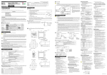
1
User’s
Manual
Models UT351 / UT321
Digital Indicating Controllers
with Active Color PV Display
User’s Manual Installation
IM 05D01D12-01E
3rd Edition: Apr. 1, 2003
This manual describes installation, wiring, and other tasks required to make the controller ready for operation.
Contents
NOTE
CAUTION
To install the controller, select a location where:
(1) no one may accidentally touch the terminals,
(2) mechanical vibrations are minimal,
(3) corrosive gas is minimal,
(4) temperature can be maintained at about 23°C and the fluctuation is minimal,
(5) no direct radiant heat is present,
(6) no magnetic disturbances are caused,
(7) no wind blows against the terminal board (reference junction compensation
element),
(8) no water is splashed,
(9) no flammable materials are around,
Turn off the power to the controller before installing it on the panel because there is a possibility of electric shock.
150mm
Direction to insert the
controller
(bottom mounting hardware)
NOTE
Thank you for purchasing the UT351/UT321 digital indicating controllers.
The controller is shipped from the factory with 4 hardcopy user’s manuals (A2 and A3 size) and 1 user’s manual on CDROM. The 4 user’s manuals in hardcopy format describe the operating procedures required for basic use. It is recommended
that you refer to these user’s manuals to understand [1] installation, [2] initial settings, and [3] operating procedures of the
controller.
The CD-ROM contains an User’s Manual (Reference) with descriptions of various functions and setting ranges that can be
set as necessary.
Moreover, the use of an optional parameter setting tool (model: LL100-E10) allows you to easily perform settings and
adjustments with a PC.
4. How to Connect Wires
CAUTION
● Installation Position
Install the controller at an angle within 30° from horizontal
with the front panel facing upward. Do not install it facing
downward. The position of right and left sides should be horizontal.
Front panel
of controller
Must not
exceed 30
Brief operation
and setpoint recording
Operations
Parameters
Describes examples of setting PV input types, control output
types, and alarm types. Making settings described herein
allows you to carry out basic control.
Describes key operation sequences. For operation control
through external contact inputs, see the back of Installation
User’s Manual.
Contains the parameter map used as a guideline for setting
parameters and lists of parameters for recording User Settings.
A2-size paper,
front
Unit: mm
11
96
100
Large bracket
A2-size paper,
back
A2-size paper,
back and front
Basic operation of
Setting / explanation Describes the setting/explanation of Active Color PV Display.
Active Color PV Display
of Active Color PV Display
A3-size paper,
back and front
Detailed description
of functions
CD-ROM
User’s Manual Describes functions more advanced than those explained in
the 3 hardcopy user’s manuals.
(Reference)
UT351
UT351/UT321
Small bracket
1 to 10 mm (Panel thickness)
The following symbol is indicated on the controller to ensure safe use.
General installation
UT351/UT321
External DC power supply
CAUTION
117 min.
[(N-1)96+92]
+0.8
0
+0.8
0
92
145 min.
CR filter
(Mount it directly
to the relay coil
terminal (socket).)
Power supply, grounding, relay contact outputs 600 V PVC insulated wires, JIS C 3307, 0.9 to 2.0 mm2
"N" stands for the number of controllers to be
installed.
However, the measured value applies if N 5.
+0.8
92 0
Shielded compensating lead wires, JIS C 1610,
(See Yokogawa Electric's GS 6B1U1-E.)
X-
-
92
RTD
Shielded wires (three conductors), UL2482 (Hitachi Cable)
Other signals
Shielded wires
(25)
Applicable wire size
0.3 to 1.65 mm2
UT321
100
Before using the controller, check that the model and suffix codes match your order.
Suffix Code
UT351
Optional functions
Standard type
Heating/cooling type
Standard type (with 24 V DC loop power supply)
0
1
2
Target Model
None
With communication, heater burnout alarm
With heater burnout alarm
Check that the following items are provided:
General installation
Side-by-side close installation
70 min.
[(N-1)48+45]
+0.6
0
+0.8
0
Digital indicating controller (of ordered model): ........................................... 1
Brackets (mounting hardware): ...................................................................... 1 pair
Unit label: ....................................................................................................... 1
User’s Manuals: .............................................................................................. 3 (A2 size)
User’s Manuals “Setting/Explanation of Active Color PV Display”: ............ 1 (A3 size)
User’s Manual (Reference) (CD-ROM version): ........................................... 1
or
Part Number
Sales Unit
For UT351
T9115YD
1
For UT321
T9115YE
1
2. Fit the holes on the top and bottom of the terminal cover
the projections on the brackets (Fig. B) and lock in
place. The figure right shows the attachment of a
terminal cover to UT controller.
92
Fold the cover in the direction
of the arrow.
Figure A
Fit the cover hold
over the protrusion
on the mounting bracket.
"N" stands for the number of controllers to be
installed.
However, the measured value applies if N 5.
+0.8
0
45
+0.6
0
1 or 2 (two for heating/cooling type),
switched between a voltage pulse output and current output.
10 ms
Number of outputs
1 or 2 (two for heating/cooling type)
Output signal
Three terminals (NC, NO, and common) /
Two terminals
Contact rating
Terminals 1 - 2 - 3 :
250 V AC or 30 V DC, 3 A (resistance load)
Terminals 4 - 7 :
240 V AC or 30 V DC, 1A (resistance load)
Resolution
10 ms
Contact Inputs
145 min.
(53)
600 or less
0.3% of span under standard operating
conditions (23 2 C, 55 10% RH,
power frequency of 50/60 Hz)
• Relay contact output (Standard type: terminals 1 - 2 - 3 ; Heating
side: terminals 1 - 2 - 3 ; Cooling side: terminals 4 - 7 )
92
•
•
•
•
•
•
Load resistance
Output accuracy
Resolution
1. Before attaching the terminal cover, bend the side with
the groove inward as shown in Fig. A. Be careful not to
bend it backwards. This not only marks it harder to
attach the cover but will also weaken its hold.
Small bracket
1 to 10 mm (Panel thickness)
4-20 mA DC
Output signal On-voltage = 12 V or more (load resistance: 600 or more)
Off-voltage = 0.1 V DC or less
3.7mm
● Terminal Covers (Optional parts)
112
-0
-2
-3
91.8
Digital indicating controller (provided with retransmission output and 15 V
DC loop power supply as standard)
UT321
Type
Description
96
Model
3.7mm
Small bracket
Output signal
Number of
outputs
0.8 N·m or less
7 mm or less
2. Model and Suffix Codes
11
1 or 2 (two for heating/cooling type),
switched between a voltage pulse output
and current output.
• Voltage pulse output (Standard type: terminals 16 - 17 ; Heating
side: terminals 16 - 17 ; Cooling side: terminals 14 - 15 )
Unit: mm
48
Number of outputs
Tightening torque
7 mm or less
Draws attention to information that is essential for understanding the operation and/or features of the controller.
+0.8
0
Universal output system, The output type can be selected
with the software.
• Current output (Standard type: terminals 16 - 17 ; Heating side:
terminals 16 - 17 ; Cooling side: terminals 14 - 15 )
-
● Recommended Terminal Lugs
IMPORTANT
•
•
•
•
Either PV, target setpoint, or control output is output.
Either the retransmission output or the loop power supply
can be used with terminals 14 - 15 .
Number of outputs: 1 (terminals 14 - 15 )
Output signal: 4-20 mA DC
Load resistance: 600 or less
Output accuracy: 0.3% of span under standard operating
conditions (23 2C, 55 10% RH, power frequency of
50/60 Hz)
Name and Manufacturer
Thermocouple
(53)
Retransmission Output
• Purpose: Selection between target setpoints or Auto/Man modes,
or for other purposes
• Number of inputs: 2
• Input type: Non-voltage contact or transistor open collector input
• Input contact rating: 12 V DC, 10 mA or more
• On/off determination: For non-voltage contact input, contact
resistance of 1 k or less is determined as “on” and contact
resistance of 20 k or more as “off.”
For transistor open collector input, input voltage of 2 V or
less is determined as “on” and leakage current must not
exceed 100 A when “off.”
• Minimum status detection hold time: About 1 second.
Contact Outputs
• Purpose: Alarm output, FAIL output, and others
• Number of outputs: 3
• Relay contact rating: 240 V AC/1 A or 30 V DC/1 A ; 1a (COM
terminal is common), (FAIL output ; 1b)
(25)
Figure B
Construction, Installation, and Wiring
• Construction: Only the front panel is dust-proof and drip-proof
(protection class IP55)
For side-by-side close installation the controller loses its
dust-proof and drip-proof protection.
• Material: ABS resin and polycarbonate
• Case color: Black
• Weight: About 1 kg or less
• Dimensions:
UT351 96 (W) 96 (H) 100 (depth from panel face)
mm
UT321 48 (W) 96 (H) 100 (depth from panel face)
mm
• Installation: Panel-mounting type. With top and bottom
mounting hardware (1 each)
• Panel cutout dimensions:
(W) 92+0.8
(H) mm
UT351 92+0.8
0
0
UT321 45+0.6
(W) 92+0.8
(H) mm
0
0
• Installation position: Up to 30° upward facing
(not designed for facing downward)
• Wiring: M3.5 screw terminals (for signal wiring and power/
ground wiring as well)
Power Supply Specifications
•
•
•
•
Power supply: Rated voltage of 100 to 240 V AC (10%), 50/60 Hz
Power consumption: Max. 20 VA (8.0 W max.)
Internal fuse rating: 250 V AC, 1.6A time-lug fuse
Data backup: Non-volatile memory (can be written to up to
100,000 times)
• Withstanding voltage
- Between primary terminals* and secondary terminals**:
At least 1500 V AC for 1 minute (Note)
- Between primary terminals* and grounding terminal:
At least 1500 V AC for 1 minute (Note)
- Between grounding terminal and secondary terminals**:
At least 1500 V AC for 1 minute
- Between secondary terminals**:
At least 500 V AC for 1 minute
* Primary terminals indicate power terminals and relay
output terminals
** Secondary terminals indicate analog I/O signal, voltage
pulse output, and contact input terminals
Note: The withstanding voltage is specified as 2300 V AC
per minute to provide a margin of safety.
• Insulation resistance: 20 M or more at 500 V DC between
power terminals and grounding terminal
• Grounding: Class 3 grounding (grounding resistance of 100 or less)
Control Output
UT’s contact
Relay
(Use one with a relay coil
rating less than the UT’s
contact rating.)
Purpose
The following symbols are used in the hardcopy user’s manuals and in the user’s manual supplied on the CD-ROM.
Indicates that operating the hardware or software in a particular manner may damage it or result in a system failure.
Diode
(Mount it directly
to the relay coil
terminal (socket).)
● Cable Specifications and Recommended Cables
This symbol on the controller indicates that the operator must refer to an explanation in the user’s manual in order
to avoid the risk of injury or death of personnel or damage to the instrument. The manual describes how the operator
should exercise special care to avoid electric shock or other dangers that may result in injury or loss of life.
NOTE
External AC power supply
R
UT’s contact
Relay
(Use one with a relay coil rating
less than the UT’s contact rating.)
Side-by-side close installation
Supplies power to a two-wire transmitter.
(15 V DC: terminals 14 - 15 ; 24 V DC: terminals 21 - 22 )
A resistor (10 to 250 ) connected between the controller
and transmitter converts a current signal into a voltage
signal, which is then read via the PV input terminal.
Supply voltage: 14.5 to 18.0 V DC, max. 21 mA (provided
with a protection circuit against a field short-circuit); 21.6
to 28.0 V DC, max. 30 mA (only for models with 24 V DC
loop power supply)
When using the 24 V DC loop power supply of the UT321,
keep the operating ambient temperature between 0C and
40C.
■ For AC Relay Wiring
R
1. Safety Precautions
Safety and EMC Standards
• Safety: Compliant with IEC1010-1: 1990 and EN61010-1:
1993+A2:1995
Approved by CSA1010
CSA1010 installation category (overvoltage category) :
CATII (IEC1010-1)
Approved by UL508
(UT321:Application for certification made)
• EMC standards: Complies with EN61326.
The instrument continues to operate at a measuring
accuracy of within 20% of the range during tests.
(UT321:To be obtained)
Loop Power Supply
1) Provide power from a single-phase instrument power supply. If there is a lot of noise in the power line, insert an
insulating transformer into the primary side of the line and use a line filter (recommended part: ZAC2205-00U
from TDK) on the secondary side.
As a countermeasures against noise, do not place the primary and secondary power cables close to each other.
2) For thermocouple input, use shielded compensating lead wires for wiring. For RTD input, use shielded wires
that have low conductor resistance and cause no significant differences in resistance between the three wires.
The cables to be used for wiring, terminal specifications, and recommended parts are as shown below.
3) Control output relays may be replaced. However, because they have a life of 100,000 times that of the resistance load, use auxiliary relays to turn on/off a load.
4) The use of inductance (L) loads such as auxiliary relays, motors and solenoid valves causes malfunction or
relay failure; always insert a CR filter for use with alternating current or a diode for use with direct current, as
a spark-removal surge suppression circuit, into the line in parallel with the load.
5) When there is possibility of being struck by external lightening surge, use the arrester to protect the instrument.
■ For DC Relay Wiring
112
Operating
procedures
and troubleshooting
Initial Settings
■ External Dimensions and Panel Cutout Dimensions
91.8
Basic operation
Media
A2-size paper,
back and front
96
Installation
Description
Describes the tasks (installation, wiring, and others) required
to make the controller ready for operations.
1) Before carrying out wiring, turn off the power to the controller and check that the cables to be connected are not
alive with a tester or the like because there is a possibility of electric shock.
2) Wiring must be carried out by personnel who have basic electrical knowledge and practical experience.
PV Input Signals
• Number of inputs: 1 (terminals 11 - 12 - 13 )
• Input type: Universal input system. The input type can be
selected with the software.
• Sampling period: 250 ms
• Burnout detection: Functions at TC, RTD, standard signal
(0.4 to 2 V or 1 to 5 V)
Upscale, downscale, and off can be specified.
For standard signal, burnout is determined to have occurred
if it is 0.1 V or less.
• Input bias current: 0.05 A (for TC or RTD b-terminal)
• Measurement current (RTD): About 0.13 mA
• Input resistance: 1 M or more for thermocouple or mV input
About 1 M for DC voltage input
• Allowable signal source resistance: 250 or less for
thermocouple or mV input
Effects of signal source resistance: 0.1 V/ or less
2 k or less for DC voltage input
Effects of signal source resistance: About 0.01%/100 • Allowable wiring resistance: for RTD input
Maximum 150 /wire: Conductor resistance between three
wires should be equal
However, 10 /wire for a maximum range of -150.0 to
150.0C.
Wire resistance effect: 0.1C /10 • Allowable input voltage: 10 V DC for thermocouple, mV, or
RTD input
20 V DC for DC voltage input
• Noise rejection ratio: 40 dB (50/60 Hz) or more in normal mode
120 dB (50/60 Hz) or more in common mode
• Reference junction compensation error: 1.0C (15 to 35C)
1.5C (0 to 15C, 35 to 50C)
• Applicable standards: JIS, IEC, DIN (ITS-90) for thermocouples
and RTD
NOTE
Rear of
controller
30
■ How to Use the Manuals
Manual Title
Insert the controller
into the opening at
the front of the panel.
Small bracket
Introduction
Purpose
(top mounting hardware)
150mm
150mm
Never touch the opening at the bottom of the case. It is to be used in the factory at shipping.
Setup
After opening the mounting hole on the
panel, follow the procedures below to install the controller:
1. Insert the controller into the opening
from the front of the panel so that the
terminal board on the rear is at the far
Terminal board
side.
2. Set the brackets in place on the top and
bottom of the controller as shown in the
figure on the left, then tighten the screws
Insert a screwdriver into the
of the brackets. Take care not to overbrackets to tighten the screws.
tighten them.
Large bracket
Panel
150mm
Never place the controller directly on flammable items or equipment.
If the controller has to be installed close to flammable items or equipment, be sure to provide shielding panels all
around the controller, at least 150mm away from every side; the panels should be made of either 1.43mm-thick
metal-plated steel plates or 1.6mm-thick uncoated steel plates.
1. Safety Precautions
2. Model and Suffix Codes
3. How to Install
4. How to Connect Wires
5. Hardware Specifications
6. Terminal Wiring Diagrams
5. Hardware Specifications
■ How to Install
3. How to Install
Display Specifications
• PV display:
UT351: 4-digit, 7-segment green or red LED display,
character height of 20 mm
UT321: 4-digit, 7-segment green or red LED display,
character height of 12 mm
• Setpoint display: 4-digit, 7-segment red LED display, character
height of 9.3 mm (for both UT351 and UT321)
• Status indicating lamps: LEDs
Signal Isolations
• PV input terminals: Isolated from other input/output terminals.
Not isolated from the internal circuit.
• 15 V DC loop power supply terminals: Not isolated from 4-20
mA analog output and voltage pulse control output. Isolated
from other input/output terminals and internal circuit.
• 24 V DC loop power supply terminals: Isolated from the 15 V
DC loop power supply terminals, 4-20 mA analog output
terminals and voltage pulse control output terminals, other
I/O terminals and the internal circuitry.
• 4-20 mA analog output terminals (for control output and
retransmission): Not isolated between 4-20 mA outputs nor
from 15 V DC loop power supply and voltage pulse control
output. Isolated from other input/output terminals and
internal circuit.
• Voltage pulse control output terminals: Not isolated from 4-20
mA outputs and 15 V DC loop power supply. Isolated from
other input/output terminals and internal circuit.
• Relay contact control output terminals: Isolated between contact
output terminals and from other input/output terminals and
internal circuit.
• Contact input terminals: Not isolated between contact input
terminals and from communication terminals. Isolated from
other input/output terminals and internal circuit.
• Relay contact alarm output terminals: Not isolated between
relay contact alarm outputs. Isolated from other input/
output terminals and internal circuit.
• RS-485 communication terminals: Not isolated from contact
input terminals. Isolated from other input/output terminals
and internal circuit.
• Power terminals: Isolated from other input/output terminals and
internal circuit.
• Grounding terminals: Isolated from other input/output terminals
and internal circuit.
Environmental Conditions
• Normal operating conditions:
Ambient temperature: 0 to 50C (40C or less for side-by-side
close installation)
When using the 24 V DC loop power supply of the UT321,
keep the operating ambient temperature between 0C and
40C.
Temperature change rate: 10C/h or less
Ambient humidity: 20 to 90% RH (no condensation allowed)
Magnetic field: 400 A/m or less
Continuous vibration at 5 to 14 Hz: Full amplitude of 1.2 mm or
less
Continuous vibration at 14 to 150 Hz: 4.9 m/s2 or less
Short-period vibration: 14.7 m/s2, 15 seconds or less
Shock: 147 m/s2 or less, 11 ms
Installation height: Height above sea level of 2000 m or less
Warm-up time: 30 minutes or more after power on
• Transportation and storage conditions:
Temperature: -25 to 70C
Temperature change rate: 20C/h or less
Humidity: 5 to 95% RH (no condensation allowed)
• Effects of changes in operating conditions
- Effects from changes in ambient temperature:
- On voltage or thermocouple input, 1 V/C or 0.01%
of F.S./C, whichever is larger
- On RTD input, 0.05C /C (ambient temperature) or less
- On analog output, 0.05% of F.S./C or less
- Effects from power supply fluctuation (within rated voltage
range)
- On analog input, 1 V/10 V or 0.01% of F.S./10 V,
whichever is larger
- On analog output, 0.05% of F.S./ 10 V or less
IM 05D01D12-01E (1)
6. Terminal Wiring Diagrams
NOTE
Do not use unassigned terminals as relay terminals.
■ UT321 Standard Type (Model UT321-0䊐 or UT321-3䊐) or Heating/Cooling type(Model UT321-2䊐)
■ UT351 Standard Type (Model UT351-0䊐 or UT351-3䊐) or Heating/Cooling type(Model UT351-2䊐)
PV input * Not configured at factory before shipment
See Initial Settings User’s Manual ,
for more information.
Note: Select this option from
* Wiring can only be carried
the OT parameter.
RS-485 communication * Wiring can only be carried out
Relay contact output
out for controllers with
* Time proportional PID
for controllers with
24 V DC loop power supply.
relay contact output is
NC
1
communication functions.
24 V DC loop
configured at factory
23 SDB(+)
Maximum baud rate: 9600 bps
power supply
NO
2
before shipment.
24 SDA(-)
COM
3
21 +
21.6-28.0VDC
25 RDB(+)
Contact rating: 250 V AC, 3 A
(30 mA DC max.)
22 30 V DC, 3 A (resistance load)
26 RDA(-)
Control output
Alarm output
27
TC input
set the PV input type to 1-5 V DC (setpoint “41”).
11 A
12 +
250 4-20mA
13 13 B
1
21
11
Alarm-3 output
AL3 4
2
22
12
Common
COM 7
3
23
13
Relay
Power supply
L
N
8
CAUTION
Before carrying out wiring, turn off the power to
the controller and check that cables to be connected
are not alive with a tester or the like because
there is a possibility of electric shock.
4
24
14
5
25
15
6
26
16
7
27
17
8
9
28
9
10
29
10
Allowable range: 100 to 240 V AC (10%)
(free voltage)
50/60 Hz shared
20
Note:Select this
option from the
OT parameter.
4-20 mA DC,
voltage pulse
(12 V)
* PV retransmission is configured at factory
before shipment.
CT
29
CT1
28
CT2
CT
30
COM
No function
2.SP when DI1=ON
1.SP when DI1=OFF
No function
AUTO when DI2=ON
MAN when DI2=OFF
No function
Common
Common
Common
Load resistance: 600 or less
15 V DC loop power supply
14 +
When DIS=2
When DIS=3
switching target
Hides the LOCK parameter when DI1=ON. When
setpoints 1 to 4:
Shows the LOCK parameter when DI1=OFF.
1.SP2.SP3.SP 4.SP
DI2 OFF OFF ON ON
Common
Common
Contact
+5V
Time proportional control
Relay output (terminals 1 , 2 and 3 )
Time proportional control
Voltage pulse output (terminals 16 and 17 )
Current output
(terminals 16 and 17 )
On-off control
Relay output (terminals 1 , 2 and 3 )
RS-485 communication * Wiring can only be carried out
COM
24
SDA(-)
25
RDB(+)
+5V
DI2
DI2 18
26
RDA(-)
19
for controllers with communication
functions.
Maximum baud rate: 9600 bps
AL2 5
12 b
21
Note: Connecting a 250 resistor to the terminals is
optional.
Model: X010-250-2 (resistor with M3.5 crimp-on terminal
lugs)
3
23
13
Relay contact rating: 240 V AC, 1 A
30 V DC, 1 A (resistance load)
4
24
14
Note: The cooling-side control output is selected if 4, 5 or
6 is set in the OT (Control Output Type) setup
parameter. The alarm-3 output is not available.
The controller is factory-set to the cooling-side control
output (time proportional PID relay contact output).
Power supply
CAUTION
Power supply
5
N
9
25
15
CAUTION
Before carrying out wiring, turn off the power
to the controller and check that cables to be
connected are not alive with a tester or the like
because there is a possibility of electric shock.
9
* This wiring is only possible
for a controller with a heater
burnout alarm.
25
* PV retransmission is configured at factory before shipment.
Retransmission output
26
Heating-side control output
Current / voltage * Available if 5, 6, 8, 9, 11
or 12 is set in the OT
pulse output
(Control Output Type)
setup parameter.
16 + 4-20 mA DC,
16
27
17
8
28
18
9
29
19
30
14 +
14 +
15
17 -
20
voltage pulse
(12 V)
15 V DC loop power supply
CT
29
CT1
28
CT2
30
COM
Retransmission output
26
16
7
27
17
8
28
18
9
29
19
10
30
20
* PV retransmission is configured at factory
before shipment.
14 +
4-20 mA DC
Control output
Current / voltage
pulse output
16 +
17 -
15 -
Note:Select this option
from the OT
parameter.
Load resistance: 600 or less
15 V DC loop power supply
4-20 mA DC,
voltage pulse
(12 V)
14 +
15 -
* If 15 V DC loop power supply is used,
retransmission output cannot be used.
14.5-18.0VDC
(21 mA DC max.)
Correspondence between parameter DIS and external contact input functions
29
CT1
28
CT2
When DIS=OFF
When DIS=1 (Factory-set default)
No function
2.SP when DI1=ON
1.SP when DI1=OFF
No function
AUTO when DI2=ON
MAN when DI2=OFF
No function
Common
Common
COM
Common
When DIS=2
When DIS=3
switching target
Hides the LOCK parameter when DI1=ON. When
setpoints 1 to 4:
Shows the LOCK parameter when DI1=OFF.
1.SP2.SP3.SP 4.SP
When DIS=4
Contact
UT
+5V
DI2 OFF OFF ON ON
Common
Common
Transistor contact
DI1
2.SP when DI1=ON DI1
19
1.SP when DI1=OFF
STOP when DI2=ON
RUN when DI2=OFF
DI1 OFF ON OFF ON
19
+5V
DI2
DI2 18
18
COM
20
COM 20
Contact rating: 12 V DC, 10 mA or more
Note: External Contact Input
If the power is turned on when the external contact input is OFF,
the mode (SP.no or A/M) existing before the power is turned
off will be continued. (except for RUN/STOP)
OT=1
OT=2
OT=3
Time proportional control
Relay output (terminals 1 , 2 and 3 )
Time proportional control
Voltage pulse output (terminals 16 and 17 )
Current output
(terminals 16 and 17 )
On-off control
Relay output (terminals 1 , 2 and 3 )
2
4-20 mA DC
15 -
15 -
14.5-18.0VDC
(21 mA DC max.)
Alarm-1 output
AL1 6
Alarm-2 output
AL2 5
UT
Alarm-3 output
or cooling-side control AL3 4
output (Note)
COM 7
Common
14 +
4-20 mA DC,
voltage pulse (12 V)
15 -
* If 15 V DC loop power supply is used,
retransmission output cannot be used.
N
Note: The cooling-side control output
is selected if 4, 5 or 6 is set in
the OT (Control Output
Type) setup parameter.
The alarm-3 output is not
available. The controller is
factory-set to the cooling-side
control output (time proportional
PID relay contact output).
CAUTION
8
9
Before carrying out wiring, turn off the power
to the controller and check that cables to be
connected are not alive with a tester or the like
because there is a possibility of electric shock.
10
* The retransmission output and 15 V DC
loop power supply are not available
if the cooling-side control output is set to
“current output” and “voltage pulse output.”
When DIS=OFF
When DIS=1 (Factory-set default)
When DIS=2
No function
2.SP when DI1=ON
1.SP when DI1=OFF
No function
AUTO when DI2=ON
MAN when DI2=OFF
No function
Common
Common
Common
When DIS=3
switching target
Hides the LOCK parameter when DI1=ON. When
setpoints 1 to 4:
Shows the LOCK parameter when DI1=OFF.
1.SP2.SP3.SP 4.SP
When DIS=4
2.SP when DI1=ON
1.SP when DI1=OFF
DI2 OFF OFF ON ON
STOP when DI2=ON
RUN when DI2=OFF
Common
Common
DI1 OFF ON OFF ON
CT
UT
DI1 19
Contact
+5V
Transistor contact
DI1
+5V
DI2
DI2 18
19
18
Note: External Contact Input
If the power is turned on when
the external contact input is OFF,
the mode (SP.no or A/M) existing
before the power is turned off will
be continued. (except for RUN/
STOP)
20
12 +
12 b
250 4-20mA
RDA(-)
27
SG
13 -
13 B
mV/V input
NOTE
13 -
Installation category (overvoltage category): II (IEC1010-1)
1
21
11
2
22
12
3
23
13
4
24
14
5
25
15
6
26
16
7
27
17
8
28
18
9
29
19
30
20
* PV retransmission is configured at factory before shipment.
Retransmission output
15 V DC loop power supply
14 +
14 +
4-20 mA DC
17 -
15 -
15 -
Heating-side control output
* Available if 5, 6, 8, 9,
Current / voltage
11 or 12 is set in the OT
pulse output
(Control Output Type)
setup parameter.
+
16
4-20 mA DC,
Cooling-side control output
voltage pulse
(12 V)
14 +
15 -
4-20 mA DC,
voltage pulse (12 V)
14.5-18.0VDC
(21 mA DC max.)
* If 15 V DC loop power supply is used,
retransmission output cannot be used.
* The retransmission output and 15 V DC
loop power supply are not available
if the cooling-side control output is set to
“current output” and “voltage pulse output.”
* DIS is a setup parameter.
Changing DIS setpoint allows you to change the function of external contact input.
Heater current
detection input
29
CT
28
CT1
CT2
CT
30
COM
Correspondence between parameter DIS and external contact input functions
When DIS=OFF
When DIS=1 (Factory-set default)
No function
2.SP when DI1=ON
1.SP when DI1=OFF
No function
AUTO when DI2=ON
MAN when DI2=OFF
No function
Common
Common
Common
When DIS=2
When DIS=3
switching target
Hides the LOCK parameter when DI1=ON. When
setpoins 1 to 4:
Shows the LOCK parameter when DI1=OFF.
1.SP2.SP3.SP 4.SP
When DIS=4
2.SP when DI1=ON
1.SP when DI1=OFF
DI2 OFF OFF ON ON
STOP when DI2=ON
RUN when DI2=OFF
Common
Common
DI1 OFF ON OFF ON
UT
DI1 19
Contact
DI2 18
+5V
Transistor contact
DI1
+5V
DI2
19
18
COM
20
COM 20
Note: External Contact Input
If the power is turned on when
the external contact input is OFF,
the mode (SP.no or A/M) existing
before the power is turned off will
be continued. (except for RUN/
STOP)
Contact rating: 12 V DC, 10 mA or more
15 V DC Power Supply Wiring to Two-wire Sensor
Contact rating: 12 V DC, 10 mA or more
* OT is a setup parameter. You can change the settings of the parameter OT to change the control output type.
See Initial Settings User’s Manual , for more information.
Note: Connecting a 250 resistor to the terminals is
optional.
Model: X010-250-2 (resistor with M3.5 crimp-on terminal
lugs)
12 +
* OT is a setup parameter.
You can change the settings of the parameter OT to change the control output type.
See Initial Settings User’s Manual , for more information.
COM
COM 20
26
10
Allowable range: 100 to 240 V AC (10%)
(free voltage)
50/60 Hz shared
* This wiring is only possible
for a controller with a
heater burnout alarm.
Correspondence between parameter DIS and external contact input functions
11 A
SDA(-)
13 -
Power supply
Power supply
set the PV input type to 1-5 V DC (setpoint “41”).
12 +
24
25 RDB(+)
Alarm output/cooling-side control output
* When receiving 4-20 mA DC current signals,
RTD input
TC input
3
L
Cooling-side control output
for controllers with communication
functions.
Maximum baud rate: 9600 bps
23 SDB(+)
䊏 Receiving 4-20 mA DC Current
Signals with the Controller
PV input * Not configured at factory before shipment
See Initial Settings User’s Manual ,
for more information.
RS-485 communication * Wiring can only be carried out
* Time proportional PID relay contact
output is configured at factory
before shipment.
* Available if 4, 7 or 10 is set in the OT
(Control Output Type) setup parameter.
Relay contact rating: 240 V AC, 1 A
30 V DC, 1 A (resistance load)
* DIS is a setup parameter.
Changing DIS setpoint allows you to change the function of external contact input.
Heater current
detection input
6
NOTE
Installation category (overvoltage category): II (IEC1010-1)
OT=0 (factory-set default)
10
Allowable range: 100 to 240 V AC (10%)
(free voltage)
50/60 Hz shared
Note: Connecting a 250 resistor to the terminals is
optional.
Model: X010-250-2 (resistor with M3.5 crimp-on terminal
lugs)
* DIS is a setup parameter.
Changing DIS setpoint allows you to change the function of external contact input.
Heater current
detection input
NOTE
11
12
10
5
Contact rating: 250 V AC, 3 A
30 V DC, 3 A (resistance load)
mV/V input
22
8
14
1
COM
13 -
13 B
2
L
13
24
Relay contact output
NO
Installation category (overvoltage category): II (IEC1010-1)
Before carrying out wiring, turn off the power to the
controller and check that cables to be connected
are not alive with a tester or the like because there
is a possibility of electric shock.
mV/V input
Heating-side control output
250 4-20mA
13 -
7
13 -
13 B
Correspondence between parameter OT and the control output types
12 +
12 +
6
250 4-20mA
13 -
* OT is a setup parameter. You can change the settings of the parameter OT to change the control output type.
See Initial Settings User’s Manual , for more information.
NC
SG
1
23
4
30
set the PV input type to 1-5 V DC (setpoint “41”).
11 A
UT
Alarm-3 output
or cooling-side control AL3 4
output (Note)
COM 7
Common
3
CT
Relay
Relay
Alarm-2 output
COM 7
18
* When receiving 4-20 mA DC current signals,
RTD input
TC input
Alarm output/cooling-side control output
27
Common
CT
䊏 Receiving 4-20 mA DC Current
Signals with the Controller
13 -
AL1 6
12
20
COM 20
PV input * Not configured at factory before shipment
See Initial Settings User’s Manual ,
for more information.
3
Alarm-1 output
22
COM
12 +
Contact rating: 250 V AC, 3 A
30 V DC, 3 A (resistance load)
2
8
12 +
12 b
■ UT321 Heating/Cooling Type (Model UT321-2䊐)
Heating-side control output
23
AL3 4
* This wiring is only
possible for a controller
with a heater burnout
alarm.
Transistor contact
DI1
11 A
12 +
13 -
10
Contact rating: 12 V DC, 10 mA or more
OT=3
2
Alarm-3 output
L
■ UT351 Heating/Cooling Type (Model UT351-2䊐)
NO
11
Power supply
Note: External Contact Input
If the power is turned on when the external contact input is OFF,
the mode (SP.no or A/M) existing before the power is turned
off will be continued. (except for RUN/STOP)
OT=2
SDB(+)
21
* If 15 V DC loop power supply is used,
retransmission output cannot be used.
UT
DI1 19
2.SP when DI1=ON
1.SP when DI1=OFF
STOP when DI2=ON
RUN when DI2=OFF
DI1 OFF ON OFF ON
OT=1
1
1
14.5-18.0VDC
(21 mA DC max.)
When DIS=4
Correspondence between parameter OT and control output types
NC
SG
Allowable range: 100 to 240 V AC (10%)
(free voltage)
50/60 Hz shared
OT=0 (factory-set default)
* Time proportional PID relay contact output
is configured at factory before shipment.
* Available if 4, 7 or 10 is set in the OT
(Control Output Type) setup parameter.
27
set the PV input type to 1-5 V DC (setpoint “41”).
12 +
AL2 5
N
* OT is a setup parameter. You can change the settings of the parameter OT to change the control output type.
See Initial Settings User’s Manual , for more information.
Relay contact output
RDA(-)
Alarm-2 output
Power supply
Correspondence between parameter DIS and external contact input functions
When DIS=1 (Factory-set default)
26
AL1 6
Relay contact rating: 240 V AC, 1 A
30 V DC, 1 A (resistance load)
15 -
15 -
When DIS=OFF
UT
Alarm-1 output
NOTE
* DIS is a setup parameter.
Changing DIS setpoint allows you to change the function of external contact input.
Heater current
detection input
* This wiring is only
possible for a controller
with a heater burnout
alarm.
30
22 -
* When receiving 4-20 mA DC current signals,
RTD input
21.6-28.0VDC
(30 mA DC max.)
4-20 mA DC
Control output
Current / voltage
pulse output
17 -
21 +
SDA(-)
TC input
Alarm output
14 +
19
24
25 RDB(+)
Note: Connecting a 250 resistor to the terminals is
optional.
Model: X010-250-2 (resistor with M3.5 crimp-on terminal
lugs)
Retransmission output
16 +
3
Contact rating: 250 V AC, 3 A
30 V DC, 3 A (resistance load)
Installation category (overvoltage category): II (IEC1010-1)
18
2
Note: Select this option from
* Wiring can only be carried
the OT parameter.
out for controllers with
* Time proportional PID
24 V DC loop power supply.
relay contact output is RS-485 communication * Wiring can only be carried out
24 V DC loop
for controllers with
configured at factory
communication functions.
power supply
before shipment.
23 SDB(+)
Maximum baud rate: 9600 bps
mV/V input
13 -
Relay contact rating: 240 V AC, 1 A
30 V DC, 1 A (resistance load)
NO
Relay
AL2 5
1
COM
13 -
12 +
Alarm-2 output
NC
12 +
12 b
SG
AL1 6
Relay contact output
䊏 Receiving 4-20 mA DC Current
Signals with the Controller
PV input * Not configured at factory before shipment
See Initial Settings User’s Manual ,
for more information.
Control output
* When receiving 4-20 mA DC current signals,
RTD input
UT
Alarm-1 output
Power supply
䊏 Receiving 4-20 mA DC Current
Signals with the Controller
* Wiring can only be carried out for controllers with 24 V DC
loop power supply.
24 V DC Power Supply Wiring to Two-wire Sensor
Correspondence between parameter OT and heating-side/cooling-side output types
Correspondence between parameter OT and heating-side/cooling-side output types
OT=4 (factory-set default)
OT=5
OT=6
OT=7
OT=8
OT=9
OT=10
OT=11
OT=12
Heating side: Relay output
(terminals 1 , 2 and 3 )
Cooling side: Relay output
(terminals 4 and 7 )
Heating side: Voltage pulse output
(terminals 16 and 17 )
Cooling side: Relay output
(terminals 4 and 7 )
Heating side: Current output
(terminals 16 and 17 )
Cooling side: Relay output
(terminals 4 and 7 )
Heating side: Relay output
(terminals 1 , 2 and 3 )
Cooling side: Voltage pulse output
(terminals 14 and 15 )
Heating side: Voltage pulse output
(terminals 16 and 17 )
Cooling side: Voltage pulse output
(terminals 14 and 15 )
Heating side: Current output
(terminals 16 and 17 )
Cooling side: Voltage pulse output
(terminals 14 and 15 )
Heating side: Relay output
(terminals 1 , 2 and 3 )
Cooling side: Current output
(terminals 14 and 15 )
Heating side: Voltage pulse output
(terminals 16 and 17 )
Cooling side: Current output
(terminals 14 and 15 )
Heating side: Current output
(terminals 16 and 17 )
Cooling side: Current output
(terminals 14 and 15 )
The control output types, “relay output” and “voltage pulse output” shown in the table above refer to those of time proportional control.
To change the type to a relay output for on-off control, select “Relay Terminals” and change the setpoint of the proportional band to “0.”
OT=4 (factory-set default)
OT=5
OT=6
Heating side: Relay output
(terminals 1 , 2 and 3 )
Cooling side: Relay output
(terminals 4 and 7 )
Heating side: Voltage pulse output
(terminals 16 and 17 )
Cooling side: Relay output
(terminals 4 and 7 )
Heating side: Current output
(terminals 16 and 17 )
Cooling side: Relay output
(terminals 4 and 7 )
OT=7
OT=8
OT=9
Heating side: Relay output
(terminals 1 , 2 and 3 )
Cooling side: Voltage pulse output
(terminals 14 and 15 )
Heating side: Voltage pulse output
(terminals 16 and 17 )
Cooling side: Voltage pulse output
(terminals 14 and 15 )
Heating side: Current output
(terminals 16 and 17 )
Cooling side: Voltage pulse output
(terminals 14 and 15 )
OT=10
OT=11
OT=12
Heating side: Relay output
(terminals 1 , 2 and 3 )
Cooling side: Current output
(terminals 14 and 15 )
Heating side: Voltage pulse output
(terminals 16 and 17 )
Cooling side: Current output
(terminals 14 and 15 )
Heating side: Current output
(terminals 16 and 17 )
Cooling side: Current output
(terminals 14 and 15 )
The control output types, “relay output” and “voltage pulse output” shown in the table above refer to those of time proportional control.
To change the type to a relay output for on-off control, select “Relay Terminals” and change the setpoint of the proportional band to “0.”
12
External
resistor 100
(Note)
12
PV input
0.4 to 2.0 V DC signal
External
resistor 250
(Note)
13
Two-wire transmitter
13
Two-wire transmitter
14
4-20mADC
15
PV input
1 to 5 V DC signal
Loop power
supply
14.5 to
18.0 V DC
Note: Connecting a 100 resistor to the terminals is optional.
Model: X010-100-2 (resistor with M3.5 crimp-on terminal lugs)
21
Loop power
supply
21.6 to
28.0 V DC
4-20mADC
22
Note: Connecting a 250 resistor to the terminals is optional.
Model: X010-250-2 (resistor with M3.5 crimp-on terminal lugs)
IM 05D01D12-01E (2)
User’s
Manual
The following operating procedure describes an example of setting the controller to a K-type thermocouple (-199.9°C to
500.0°C) and the measurement range of 0.0°C to 200.0°C.
Models UT351 / UT321
Digital Indicating Controllers
with Active Color PV Display
User’s Manual Initial Settings
IM 05D01D12-02E
1.
Display screen at power-on
The parameter “IN” for setting the PV input type
appears.
Displays
parameter “IN”.
PV
SP 2
3
7.
Press the
SET/ENT
key once to register the setpoint.
PV
SP 2
4
AL1
3rd Edition: Apr. 1, 2003
3
4
SP
SP
2
MAN
3
AL1
A/M
A/M
SET/ENT
SET/ENT
2
MAN
3
3.
NOTE
Press the
or
key to display the required
setpoint. The figure below is an example of the
controller set to a K-type thermocouple (-199.9⬚C to
500.0⬚C). See “Instrument Input Range Codes.”
This manual describes examples of setting PV input types, control output types, and alarm types. Carrying out settings
described herein allows you to perform basic control. Refer to examples of various settings to understand how to set parameters required. Refer to “1. Parameter Map” in Parameters User’s Manual for an easy to understand explanation of
setting various parameters. If you cannot remember how to carry out an operation during setting, press the
key for
more than 3 seconds. This brings you to the display (operating display) that appears at power-on.
PV
3
4
SP
AL1
2
Press the
key once to display the parameter
“RL” (minimum value of PV input range).
SET/ENT
SP 2
3
4
AL1
A/M
A/M
SET/ENT
SET/ENT
2
1. Names and Functions of Front Panel Parts
2. Setting PV Input Type (Setting First at Power-on)
3. Changing PV Input Type
4. Setting Control Output Type
5. Changing Alarm Type
6. Description of Multiple Setpoints and PID
key once to register the reqired
SET/ENT
9.
3
4
SP 2
SP
3
2
MAN
3
AL1
A/M
A/M
SET/ENT
SET/ENT
2
3
UT351
4.
1. Process
variable (PV) 2. Setpoint
display
display
2. Setpoint
display
3. Target setpoint
(SP) number
4. Status
indicator lamps
indicator
6. Light-loader
lamp
interface
9. and keys
7. A/M key
6. Light-loader
interface
7. A/M key
1.
2.
SP 2
Press the
key for more than 3 seconds to
call up the menu “OP.PA”.
SET/ENT
8. SET/ENT
key
and
2
SET/ENT
SET/ENT
5.
Press the
key once to display the parameter
“RH” (maximum value of PV input range).
SET/ENT
AL1
Displays
parameter
“RH”.
3
4
2
MAN
3
AL1
SET/ENT
SET/ENT
Press the
or
key to display the required
setpoint. The figure below shows an example of
setting the maximum value of PV input range to
200.0⬚C.
2
3
Type
Instrument Input
Range Code
OFF
K
2
3
Although only figures of the UT351 front panel are cited in “2. Setting PV Input Type (Setting First at Power-on),” and
thereafter, the UT321 is identical to the UT351 in terms of front panel operation.
J
4
5
T
■ Setting of Main Parameters at the Factory before Shipment
6
Factory-set defaults
for heating/cooling type controllers
B
Heating side: Time proportional PID relay output (variable)
Cooling side: Time proportional PID relay output (variable)
Not specified
P = 5.0%, I = 240 seconds, D = 60 seconds.
Alarm-1: PV high limit, Alarm-2: PV low limit, Alarm-3: PV high limit
S
R
N
E
NOTE
L(DIN)
3
9
10
11
12
U(DIN)
14
PV
SP 2
8
13
The controller displays the operating display when the power is
turned on. However, if PV input type has not been set, “IN”
NOTE
appears. In this case, first use the
key to display the input
range code to use, then press the
key to register it. Then,
If the display is as shown on the left,
press the
key to show the
set the maximum value (RH) and minimum value (RL) of the
range code for the PV input type you
PV input range (for voltage input, set the maximum value (SH)
use. Then, register the range code
setting by pressing the
key.
and minimum value (SL) of the PV input scale).
The controller is configured to the initial value of each parameter at the factory before shipment.
First check the initial values shown in “2. Lists of Parameters,” in Parameters User’s Manual and change
parameter values as necessary.
SET/ENT
7
Thermocouple
2. Setting PV Input Type (Setting First at Power-on)
W
4
15
SP
AL1
2
3
MAN
Platinel 2
16
A/M
SET/ENT
SET/ENT
PR20-40
17
W97Re3W75Re25
18
30
JPt100
31
Example of Temperature Input
-200°C
1370°C
Example of Voltage Input
1V
2V
PV input range
800°C
Set a range
to be
controlled
Maximum value of
PV input range (RH)
Parameters to be set for temperature input
1. PV input type (IN): Set according to a sensor
2. Maximum value of PV input range (RH): Set the
maximum value of the range to be controlled.
3. Minimum value of PV input range (RL): Set the
minimum value of the range to be controlled.
4V
5V
(input signal)
RTD
Instrument
input range
Instrument
input range
Minimum value of
PV input range (RL)
4
RL
PV input range
36
37
RH
PV input scale
0.0m3/h
35
Pt100
Set a range to
be controlled
Standard
signal
50.0m3/h
Minimum value of
Maximum value of
PV input scale (SL)
PV input scale (SH)
Parameters to be set for voltage input
1. PV input type (IN): Set according to an input signal
2. Maximum value of PV input range (RH): Set the maximum value of an input signal.
3. Minimum value of PV input range (RL): Set the minimum value of an input signal.
4. Position of PV input decimal point (SDP): Set the position of the decimal point for PV input display.
5. Maximum value of PV input scale (SH): Set the maximum value of the scale to be controlled.
6. Minimum value of PV input scale (SL): Set the minimum value of the scale to be controlled.
AL1
MAN
3
A/M
A/M
SET/ENT
3
4
5.
Press the
“FUNC”.
SET/ENT
key once to display the menu
Press the
key once to display the parameter
“RH” (maximum value of PV input range).
9.
DC voltage
0.4 to 2 V
1 to 5 V
0 to 2 V
0 to 10 V
-10 to 20 mV
0 to 100 mV
Press the
2
4
MAN
3
Blinks during
change.
key once to register the setpoint.
SET/ENT
Displays
menu “FUNC”.
PV
AL1
3
PV
4
SP 2
SP 2
3
6.
Displays
parameter
“RH”.
PV
AL1
SET/ENT
12.
key once to display the menu
4
Press the
MAN
3
AL1
A/M
A/M
SET/ENT
SET/ENT
key once to display the menu “I/O”.
2
10.
Displays menu
“STUP”.
PV
SP 2
3
4
MAN
3
SET/ENT
3
Displays
PV.
PV
SP 2
4
2
SP 2
MAN
3
AL1
A/M
A/M
SET/ENT
SET/ENT
key once to display the parameter
13.
Press the
SET/ENT
3
4
SP
2
MAN
3
AL1
A/M
A/M
SET/ENT
SET/ENT
2
Displays target
setpoint
MAN
3
5. Changing Alarm Type
PV
4
3
The following operating procedure describes an example of changAlarm output terminals
Factory-set defaults
ing alarm-1 (factory-set default: PV high limit alarm) to PV low Alarm-1 (terminal numbers 6 - 7 ).......PV input high limit alarm
limit alarm.
Alarm-2 (terminal numbers 5 - 7 ).......PV input low limit alarm
When you have changed alarm type, the alarm setpoint will be ini- Alarm-3 (terminal numbers 4 - 7 ).......PV input high limit alarm
tialized; set the alarm setpoint again.
For details see “List of Alarm Types” in Parameters
4
SP
AL1
SET/ENT
2
Press the
key for more than 3 seconds.
This returns you to the display shown at power-on
(figure below).
Displays
menu “I/O”.
MAN
3
Press the
or
key to display the required
setpoint. The figure below shows an example of
setting the maximum value of PV input range to
200.0°C.
SP
Press the
“PWD”.
3
SP
2
SET/ENT
SET/ENT
SP 2
Displays PV.
2
3
2
Blinks during
change.
MAN
3
key once to register the setpoint.
User’s Manual
MAN
The PV display in the figure above shows the error code
for input burnout (
) if PV input wiring is not yet
complete. The error code disappears when you wire the
PV input terminals correctly.
1.
PV
SP 2
3
SP 2
4
3
4
SP
SP
2
MAN
3
AL1
A/M
A/M
SET/ENT
SET/ENT
2
Bring the operating display into view (appears at
power-on).
Press the
“FUNC”.
SET/ENT
key once to display the menu
14.
SP 2
3
AL1
3
Displays
parameter
“RL”.
PV
4
SP 2
MAN
3
AL1
2
4
3
4
SP 2
2.
40
41
50
51
55
56
Instrument
Measurement Accuracy
Input Range
Set the data item PV Input Type "IN" to the OFF option to leave the PV input
type undefined.
-200 to 1370⬚C
-300 to 2500⬚F
-199.9 to 999.9⬚C
0 to 2300⬚F
⫾0.1% of instrument range ⫾1 digit for temperatures
-199.9 to 500.0⬚C
equal to or higher than 0⬚C
-199.9 to 999.9⬚F
⫾0.2% of instrument range ⫾1 digit for temperatures
-199.9 to 999.9⬚C
below 0⬚C
-300 to 2300⬚F
-199.9 to 400.0⬚C
-300 to 750⬚F
0.0 to 400.0⬚C
-199.9 to 750.0⬚F
⫾0.15% of instrument range ⫾1 digit for temperatures
0 to 1800⬚C
equal to or higher than 400⬚C
32 to 3300⬚F
⫾5% of instrument range ⫾1 digit for temperatures
below 400⬚C
0 to 1700⬚C
32 to 3100⬚F
⫾0.15% of instrument range ⫾1 digit
0 to 1700⬚C
32 to 3100⬚F
⫾0.1% of instrument range ⫾1 digit
-200 to 1300⬚C
⫾0.25% of instrument range ⫾1 digit for temperatures
-300 to 2400⬚F
below 0⬚C
-199.9 to 999.9⬚C
-300 to 1800⬚F
-199.9 to 900.0⬚C
⫾0.1% of instrument range ⫾1 digit for temperatures
-300 to 1300⬚F
equal to or higher than 0⬚C
⫾0.2% of instrument range ⫾1 digit for temperatures
-199.9 to 400.0⬚C
below 0⬚C
-300 to 750⬚F
0.0 to 400.0⬚C
-199.9 to 750.0⬚F
0 to 2300⬚C
⫾0.2% of instrument range ⫾1 digit
32 to 4200⬚F
0 to 1390⬚C
⫾0.1% of instrument range ⫾1 digit
32 to 2500⬚F
⫾0.5% of instrument range ⫾1 digit for temperatures
0 to 1900⬚C
equal to or higher than 800⬚C
32 to 3400⬚F
No guarantee of accuracy for temperatures below 800⬚C
0 to 2000⬚C
⫾0.2% of instrument range ⫾1 digit
32 to 3600⬚F
-199.9 to 500.0⬚C
⫾0.1% of instrument range ⫾1 digit (Note1) (Note2)
-199.9 to 999.9⬚F
-150.0 to 150.0⬚C
⫾0.2% of instrument range ⫾1 digit (Note1)
-199.9 to 300.0⬚F
-199.9 to 850.0⬚C
-300 to 1560⬚F
⫾0.1% of instrument range ⫾1 digit (Note1) (Note2)
-199.9 to 500.0⬚C
-199.9 to 999.9⬚F
-150.0 to 150.0⬚C
⫾0.2% of instrument range ⫾1 digit (Note1)
-199.9 to 300.0⬚F
0.400 to 2.000 V
1.000 to 5.000 V
⫾0.1% of instrument range ⫾1 digit
0.000 to 2.000 V
The read-out range can be scaled between -1999 and
0.00 to 10.00 V
9999.
-10.00 to 20.00 mV
0.0 to 100.0 mV
*
Performance in the standard operationg condition (at 23⫾2⬚C, 55⫾10%RH, and 50/60Hz power frequency)
Note1: The accuracy is ⫾0.3⬚C of instrument range ⫾1 digit for a temperature range from 0⬚C to 100⬚C.
Note2: The accuracy is ⫾0.5⬚C of instrument range ⫾1 digit for a temperature ranges from -100⬚C to 0⬚C and 100⬚C to 200⬚C.
*
To receive a 4-20 mA DC signal, select a standard signal of 1 to 5 V DC and connect it to a 250⍀ resistor. This resistor is optional.
Model: X010-250-2 (resistor with M3.5 crimp-on terminal lugs)
6.
Press the
A/M
A/M
SET/ENT
SET/ENT
key once to display the menu “I/O”.
15.
Displays target
setpoint
MAN
3
AL1
Displays
menu “I/O”.
PV
SP 2
3
SP 2
3
SET/ENT
A/M
7.
MAN
3
SP 2
AL1
A/M
A/M
SET/ENT
SET/ENT
Press the
key once to display the parameter
“IN” (PV input type).
SET/ENT
16.
Press the
SET/ENT
Displays
parameter “IN”.
PV
SP 2
3
AL1
2
3.
Blinks during
change.
MAN
3
MAN
3
SP 2
8.
AL1
A/M
A/M
SET/ENT
SET/ENT
Press the
or
key to display the required
setpoint. The figure below is an example of the
controller set to a Pt100 resistance temperature
detector (-199.9°C to 500.0°C).
PV
SP 2
3
4
SP
AL1
2
17.
Press the
“STUP”.
A/M
SET/ENT
SET/ENT
AL1
2
3
4.
4
MAN
3
4
MAN
3
You can take the same
steps for alarm-2 type
(AL2), and alarm-3 type
(AL3) that are displayed
after this.
PV
SP 2
4
MAN
3
AL1
A/M
A/M
SET/ENT
SET/ENT
2
3
3
4
MAN
SP 2
SET/ENT
SET/ENT
2
3
key once to register the setpoint.
SP 2
5.
Displays target
setpoint
Press the
“FUNC”.
SET/ENT
4
Displays
PV.
PV
AL1
* If the type of input is voltage, also configure
the PV Input Decimal Point Position (SDP),
Maximim Value of PV Input Scale (SH) and
Minimum Value of PV Input Scale (SL) that are
displayed after parameter RL.
PV
SET/ENT
3
4
SP 2
SP
4
MAN
3
Press the
key for more than 3 seconds.
This returns you to the display shown at power-on
(figure below).
PV
SP
AL1
9.
SET/ENT
Displays
PV.
PV
Blinks during
change.
A/M
3
3
3
key once to register the setpoint.
SET/ENT
SP
2
Press the
key once to display the
parameter “PWD”.
SET/ENT
A/M
SP 2
Press the
SP
3
4
SP
2
MAN
3
AL1
A/M
A/M
SET/ENT
SET/ENT
key once to display the menu
2
3
Displays target
setpoint
MAN
10. When setting an alarm setpoint, see “4. Setting
Alarm Setpoints” in Operations User’s Manual .
Displays menu
“FUNC”.
SP 2
Press the
8.
Display menu
“STUP”.
PV
9.
2
Blinks during
change.
A/M
key once to display the menu
Press the
key for more than 3 seconds.
This returns you to the display shown at power-on
(figure below).
MAN
3
AL1
PV
4
MAN
3
SP 2
SP
2
PV
SP
2
PV
4
SET/ENT
key once to register the setpoint.
SP
AL1
3
SP
SP 2
7.
Press the
or
key to display the required
setpoint. The figure below shows an example of
setting PV low limit alarm.
Displays menu
“OP.PA”.
PV
4
SP
2
4
MAN
3
PV
4
SP
AL1
2
SET/ENT
Press the
key for more than 3 seconds to
call up the menu “OP.PA”.
Press the
or
key to display the required
setpoint. The figure below shows an example of
setting the minimum value of PV input range to
0.0°C.
3
SP
2
MAN
3
Displays
parameter
“AL1”.
PV
SET/ENT
SP
2
SET/ENT
SP
SET/ENT
SP
Press the
key several times to display the
parameter “AL1” (alarm-1 type).
Displays
PV.
PV
Press the
key once to display the parameter
“RL” (minimum value of PV input range).
Displays
menu “FUNC”.
6.
MAN
3
SP 2
5.
PV
Select the unit from the UNIT parameter.
The controller automatically returns to the display at the time of power-on (i.e., operating display) if no key is
operated for at least one minute.
0°C
3
■ Instrument Input Range Codes
Input
3
SP
2
AL1
Press the
“STUP”.
Blinks during
change.
MAN
1
Time proportional PID
relay output (variable)
Reverse action (variable)
SP 2
4
SET/ENT
Unspecified
Factory-set defaults
for standard type
controllers
3
SET/ENT
SP
A/M
AL1
Used to change numerical values. On setting displays for various parameters, you can change
target setpoints, parameters, and output values (in manual operation). Pressing the
key
decreases a numerical value, while pressing the
key causes it to increase. You can hold
down a key to gradually increase the speed of change.
4
MAN
Press the
or
key to display the required
setpoint. The figure below shows an example of
setting to current output (4 to 20 mA DC).
SP
SET/ENT
MAN
3
4
SP
Used to switch or register a parameter. Pressing the key for more than 3 seconds allows you to switch
between the operating display and the menu for operating parameter setting display alternately.
SET/ENT
3
A/M
Used to switch between the AUTO and MAN modes. Each time you press the key, it switches to
the AUTO or MAN mode alternately.
3
3
PV
SP 2
A/M
IMPORTANT
•
SP 2
A/M
AL1
8.
SP
3.
4.
PV
A/M
Interface for an adapter cable used when setting and storing parameters from a PC.
This requires an optional parameter setting tool.
and
keys
•
MAN
3
2
AL1
6.
key once to display the parameter
PV
MAN
3
PV
A/M
Control action
PID parameter
Alarm output
4
2
4
If any of alarms 1 to 3 occurs, the respective alarm indicator lamp (AL1 to AL3) is lit (in orange).
Light-loader interface
Control output
11.
PV
Displays the setpoint (SP) or the output value (OUT) during operation.
Displays the set value of parameters on the parameter setting display.
Alarm indicator lamps
Item
11.
A/M
SET/ENT
2
SP
SP 2
9.
3
To set the type of control output, see steps 7 and later in
“4. Setting Control Output Type.” To finish settings, press
key for more than 3 seconds. This returns you
the
to the display shown at power-on (figure below).
SP
Is lit in green during manual operation. MAN: Is lit when in manual mode.
Blinks during auto-tuning
SET/ENT
key
2
A/M
SET/ENT
A/M
A/M
SET/ENT
SP 2
Status indicator lamp
8.
AL1
A/M
Displays PV.
Displays a parameter symbol when you set a parameter.
Displays an error code (in red) if an error occurs.
4.
A/M key
SP 2
MAN
3
PV
Target setpoint (SP)
number indicator lamps
7.
If the type of input is
voltage, also configure
the PV Input Decimal
Point Position (SDP),
Maximim Value of PV
Input Scale (SH) and
Minimum Value of PV
Input Scale (SL) that
follow this step.
PV
SP
AL1
AL1
SP
AL1
key once to register the setpoint.
4
keys
3.
6.
Press the
A/M
Function
Setpoint display
3
PV
9.
Process variable (PV)
display
3
10.
SET/ENT
MAN
3
SP 2
Displays
menu “OP.PA”.
PV
SP
5. Alarm indicator
lamps
When the SP number currently used for operation is 2, 3 or 4, the respective SP No. indicator lamp lighits.
When the SP number is 1, the lamp does not lighit.
5.
Press the
key once to display the parameter
“UNIT” (PV Input Unit).
Displays
parameter
PV
“UNIT”.
SET/ENT
1. Process
variable (PV)
display
4. Status
indicator lamp
8. SET/ENT key
Name of Part
AL1
SP
UT321
3. Target setpoint
(SP) number
indicator lamps
5. Alarm
indicator
lamps
SP 2
Displays target
setpoint
SET/ENT
SP 2
1. Names and Functions of Front Panel Parts
Displays
parameter
“UNIT”.
PV
4
MAN
3
Blinks during
change.
MAN
3
2
A/M
4
SP
AL1
SET/ENT
SP
AL1
2.
PV
SP 2
SP 2
4
Displays
parameter
“OT”.
SP
2
SET/ENT
SP
Press the
or
key to display the required
setpoint. The figure below shows an example of
setting the minimum value of PV input range to
0.0⬚C.
PV
Press the
“PWD”.
Press the
key once to display the parameter
“UNIT” (PV input unit).
Displays
PV.
PV
SP 2
Press the
setpoint.
10.
3
PV
MAN
3
Contents
3.
SP 2
AL1
4.
Bring the operating display into view (display
appears at power on).
SET/ENT
SP
AL1
1.
Press the
key several times to display the
parameter “OT” (control output type).
Displays menu
“STUP”.
PV
The following operating procedure describes an example of changing PV input terminal
the K-type thermocouple (-199.9°C to 500.0°C) to a Pt100 resistance Thermocouple/mV/V input.............................. 12 - 13
temerature detector (-199.9°C to 500.0°C) and setting the measure- RTD input .................................................. 11 - 12 - 13
ment range of 0.0°C to 200.0°C.
SP
MAN
3
Displays
parameter
“RL”.
PV
Blinks during
change.
SET/ENT
SP 2
8.
7.
key once to display the menu
The controller may automatically initialize the registered operating parameter setpoints if any change is made to the
data item PV Input Type (IN), Maximum Value of PV Input Range (RH), Minimum Value of PV Input Range (RL),
PV Input Decimal Point Position (SDP), Maximum Value of PV Input Scale (SH) or Minimum Value of PV Input
Scale (SL). After a change has been made to any of these data items, be sure to verify the registered operating
parameter setpoints to ensure that they are correct. If any data item has been changed to its default, set it to a
required value.
3. Changing PV Input Type
2.
Press the
“STUP”.
3
4
SP
AL1
2
3
MAN
A/M
SET/ENT
SP
AL1
2
MAN
3
6. Description of Multiple Setpoints and PID
A/M
SET/ENT
4. Setting Control Output Type
The following operating procedure describes an exControl output terminal Values in parentheses are setpoints
ample of changing time proportional PID relay outTime proportional PID relay (0)/on-off(3) output...........................
put (0: factory-set default) to current output (2).
1 - 2 Current (2)/time proportional PID voltage pulse (1) output...................... 16 - 17
For details on the heating/cooling control output terminals, see
“6. Terminal Wiring Diagrams” in Installation User’s Manual .
1.
Bring the operating display into view (display
appears at power on).
Displays
PV.
PV
SP 2
3
2.
PV
SP 2
4
A/M
SET/ENT
3
SP
2
3
MAN
Displays target
setpoint
Target
setpoint
(SP)
SP.NO=1
1.SP
1.P
1.I
1.D
1.Pc
1.Ic
1.Dc
SP.NO=2
2.SP
2.P
2.I
2.D
2.Pc
2.Ic
2.Dc
SP.NO=3
3.SP
3.P
3.I
3.D
3.Pc
3.Ic
3.Dc
SP.NO=4
4.SP
4.P
4.I
4.D
4.Pc
4.Ic
4.Dc
Press the
key for more than 3 seconds to call
up the menu “OP.PA”.
Displays
menu “OP.PA”.
AL1
2
3
MAN
4
PID parameter
Target setpoint
number
(SP.NO)
SET/ENT
SP
AL1
3
The UT351/UT321 controllers have a maximum of four target setpoint (SP) parameters and has PID for each of these
setpoints. The following shows the correspondence between the target setpoint numbers (SP.NO), target setpoints (SP), and
PID parameters.
For example, if you have set “2” to the target setpoint number (SP.NO), the control parameters available are target setpoint
(2.SP), proportional band (heating-side proportional band) (2.P), integral time (heating-side integral time) (2.I), derivative
time (heating-side derivative time) (2.D), cooling-side proportional band (2.Pc), cooling-side integral time (2.Ic), and cooling-side derivative time (2.Dc).
To use multiple target setpoints, see the table below to check the corresponding parameters.
Proportional
Integral time Derivative time Cooling-side
band
proportional
(heating-side (heating-side
(heating-side
band
integral time) derivative time)
proportional band)
Cooling-side Cooling-side
integral time derivative time
A/M
SET/ENT
IM 05D01D12-02E (1)
3.
User’s
Manual
Models UT351 / UT321
Digital Indicating Controllers
with Active Color PV Display
User’s Manual Operations
IM 05D01D02-02E
Press the
key several times to display the
parameter “PID”.
Displays
parameter
PV
“PID”.
SET/ENT
SP 2
3
7.
Press the
setpoint.
or
key to display the required
NOTE
SP 2
4.
Press the
3
MAN
3
Take note of the parameter settings when asking the vendor for repair.
4
If AUTO and MAN have been switched using contact input, when the contact input is ON, switching between
AUTO and MAN cannot be achieved by keystroke.
SP
2
AL1
A/M
A/M
SET/ENT
SET/ENT
key once to display “1Gr.”
8.
Press the
2
MAN
3
Blinks during
change.
key once to register the setpoint.
SET/ENT
1.
SP 2
AL1
SET/ENT
5.
Press the
SET/ENT
Contents
2
3
4
SP 2
SP 2
SET/ENT
SET/ENT
The same steps can be used for integral time (1.I) and
derivative time (1.D) that are displayed after this.
key once to register the setpoints.
AL1
3
2
MAN
3
A/M
Press the
key once to display the parameter
“1.P” (proportional band for 1.SP).
SET/ENT
PV
1. Setting Target Setpoint (SP)
3
4
9.
Press the
key for more than 3 seconds.
This returns you to the display shown at power-on
(figure below).
2
Displays
parameter
“1.P”.
SP 2
AL1
A/M
A/M
SET/ENT
SET/ENT
4.
Press the
setpoint.
or
Displays PV.
PV
3
A/M
SP 2
3
2.
4
SP
AL1
AL1
2
-
6
5
4
7
7
7
Factory-set defaults
)............PV high limit alarm
)............PV low limit alarm
)............PV high limit alarm
3
2
MAN
3
AL1
2
SET/ENT
SP 2
3
AL1
Blinks during
change.
5.
Press the
SET/ENT
key once to register the setpoint.
1.
2.
Bring manual operating display into view. For
switching to manual operation, see “7. Switching
between AUTO and MAN ”.
Displays
output-value
symbol “o”.
or
SP 2
AL1
2
3
Press the
or
key to change a control output
value. You don’t need to press the
key.
Faulty RAM
(E001)
Faulty ROM
(E002)
System data error 0%
PV decimal point blinks.
Faulty calibration
value
Parameter error
None
0% or less
0% or less
or OFF
Stopped
OFF
0%
Normal action Normal action Normal action Normal action
Normal
(out of
(out of
(out of
(out of
action
accuracy)
accuracy)
accuracy)
accuracy)
0%
Preset value
OFF
output
Faulty
Contact us
for repair.
Check and set
the parameters,
as they have
been set to the
limited values.
0%
4
4
SP 2
3
4
SP 2
3
MAN lamp
ON.
4
SP
AL1
MAN lamp
ON.
2
3
MAN
A/M
SET/ENT
■ Heating-side OUT display
AL1
2
MAN
3
key to display the required
A/M
A/M
SET/ENT
SET/ENT
SP 2
AL1
2
3
3
PV
Heating-side
output
%
4
MAN
Control
output
Alarm
output
Retransmis- Commusion output nication
Displays “RJC”
and PV
alternately
Measured
with RJC=OFF
Normal
action
Normal
action
Normal
action
Normal
action
Faulty
Contact us for repair.
Normal action
Normal
action
Normal
action
Normal
action
Normal
action
Faulty
Contact us for repair.
105%
Preset
value
output
Normal
action
Normal
action
Normal
action
Dependent on the BSL
parameter Up-scale: 105%
Down-scale: -5%
Preset
value
output
Normal
action
Normal
action
Normal
action
Check wires and
sensor.
Normal
action
Normal
action
Normal
action
Normal
action
Check process.
Normal
action
Normal
action
Normal
action
Normal
action
Check process. Press
any key to erase error
indication.
Normal
action
Normal
action
Normal
action
Normal
action
Check wires and
communication parameters,
and make resetting.
Recovery at normal receipt
RJC error
PV value blinks. EEPROM
error
(E300)
A/DC error
SP 2
Symbol “C”
represents the
cooling-side
output.
A/M
SET/ENT
3
Cooling-side
output
%
4
SP
AL1
2
3
MAN
(OVER) or Excessive PV -5% or 105%
(-OVER) Out of -5 to
105%
(E200) Auto-tuning Normal action
failure
(Time-out)
SP decimal
point blinks.
(on setpoint
display unit)
■ Cooling-side OUT display
SP
PV
(B.OUT) PV burnout
error
PV
■ Manipulating the Control Output during Heating/Cooling Control
Symbol “H”
represents the
heating-side
output.
Error indication Description
(on PV display of error
unit)
SET/ENT
MAN
3
PV
MAN
3
Remedy
The following shows possible errors occurring during operations.
key. Note that the control output changes
Displays
output value.
%
SP
PV
SP
2
Retransmission Communioutput
cation
■ Possible Errors during Operation
MAN
3
A/M
Displays menu
“OP.PA”.
PV
Alarm
output
MAN lamp
ON.
A/M
SET/ENT
4
SET/ENT
SET/ENT
(E000)
(E400)
Control output cannot be changed if the controller is stopped. In this case, the preset output value (setup parameter
PO) will be output.
SET/ENT
SP 2
Displays
target setpoint.
MAN
3
Control
output
MAN
3
NOTE
Displays
target setpoint.
MAN
3
key to display the required
SP
or
SP
8. Manipulating the Control Output in Manual Operation
PV
Press the
key for more than 3 seconds to call
up the menu “OP.PA”.
A/M
SET/ENT
Press the
setpoint.
4
Either of the following two displays appears when the mode is switched to MAN during heating/cooling control.
Displays
target setpoint.
MAN
3
MAN lamp
OFF.
A/M
3
SP
2
A/M
PV
2
MAN
3
SP 2
4
Displays PV.
AL1
2.
2
4
key once to register the setpoint.
4
SP
2
A/M
SET/ENT
3
Displays
output-value
symbol “o”.
SP
AL1
Displays
output value.
%
PV
SET/ENT
Bring the operating display into view (display
appears at power on).
AL1
SP 2
4
A control output value is linked with a display value changed using the
as displayed without requiring the
key.
SP
PV
3
PV
SP 2
SET/ENT
3
The following operating procedure describes an example of setting Alarm output terminals
160.0 to alarm-1 setpoint. Check alarm type before setting the alarm Alarm-1 (terminal numbers
setpoint. To change the type of alarm, see “5. Changing Alarm Type” Alarm-2 (terminal numbers
Alarm-3 (terminal numbers
in Initial Setting User’s Manual .
When the target setpoint is set through communication, the target setpoint cannot be changed by keystroke.
Press the
SP 2
Displays PV.
PV
MAN
3
PV
SET/ENT
4. Setting Alarm Setpoints
1.
NOTE
3.
Displays
target setpoint.
PV
SP
AL1
The following operating procedure describes an example of setting 120.0 to a target setpoint. In automatic operation, the
controller starts control using set target setpoints.
Displays
target setpoint.
MAN
3
Each time you press the A/M key on the front panel of the instrument, AUTO and MAN is switched alternately.
In automatic operation
In manual operation
SET/ENT
SP 2
Bring the operating display into view (display
appears at power on).
2.
[TIP]
The PID parameter numbers set in step 4. should be
set as follows:
In case of PID for 1.SP, PID = 1Gr
In case of PID for 2.SP, PID = 2Gr
In case of PID for 3.SP, PID = 3Gr
In case of PID for 4.SP, PID = 4Gr
4
SET/ENT
Do not use the instrument generating strong magnetic field such as radio equipment and the like near the controller.
This may cause the fluctuation of the PV value.
2
MAN
3
SET/ENT
SP
1.
2
A/M
A/M
SP
NOTE
4
4
AL1
A/M
SP 2
6.
3
SP
AL1
PV
1. Setting Target Setpoint (SP)
2. Performing/Canceling Auto-tuning
3. Setting PID Manually
4. Setting Alarm Setpoints
5. Selecting Target Setpoint Numbers (SP.NO)
6. Switching between Run and Stop
7. Switching between AUTO and MAN
8. Manipulating the Control Output in Manual Operation
9. Troubleshooting
3
SP
MAN
3
Description
of error
PV
Blinks during
change.
SP
Error indication
(on PV display unit)
Displays PV.
PV
PV
■ Errors at Power On
The following table shows errors that may be detected by the fault diagnosis function when the power is turned on.
Bring the operating display into view (display appears at power on).
3rd Edition: Apr. 1, 2003
This manual describes key entries for operating the controller. For operations using external contact inputs, see “6. Terminal
Wiring Diagrams” in Installation User’s Manual . If you cannot remember how to carry out an operation during
setting, press the
key for more than 3 seconds. This brings you to the display (operating display) that appears at
power-on.
IMPORTANT
PV
4
SP
AL1
7. Switching between AUTO and MAN
Faulty
communication line
Normal action
Remedy
All indications off Runaway (due None
to defective
power or
noise)
0% or less OFF
or OFF
0% or
less
Stopped
Faulty if power off/on does
not reset start the unit.
Contact us for repair.
All indications off Power off
0%
0%
Stopped
Check for abnormal power.
None
OFF
A/M
SET/ENT
PV
SP 2
3
Also configure the Alarm-2 Setpoint (A2) and Alarm3 Setpoint (A3) parameters that follow this step.
4
SP
AL1
2
MAN
3
3.
Blinks during
change.
A/M
SET/ENT
Press the
“A1”.
SET/ENT
key twice to display the parameter
PV
2. Performing/Canceling Auto-tuning
SP 2
4
NOTE
SET/ENT
Bring the operating display into view (display
appears at power on).
Displays PV.
4.
Press the
or
key to display the required
setpoint. Tuning for 1.SP is AT = 1.
PV
PV
SP 2
3
4
AL1
2
MAN
3
SP 2
Displays
target setpoint.
SP
AL1
SP 2
3
4
SP
AL1
MAN
3
AL1
A/M
A/M
SET/ENT
SET/ENT
2
4
Displays
target setpoint.
MAN
3
The following is an example when the DB parameter is set at 12.4%.
If you hold down the
key with the heating-side output under manipulation (i.e., cooling-side output C = 0.0%), the
heating-side output (H =) decreases. Consequently, both the heating-side and cooling-side outputs change to 0.0%. If you
keep the
key held down longer, you enter the state of manipulating the cooling-side output, and its value begins to
increase.
key with the cooling-side output under manipulation (i.e., heating-side output H =
Inversely, if you hold down the
0.0%), the cooling-side output (C =) decreases. Consequently, both the heating-side and cooling-side outputs go to 0.0%. If
you keep the
key held down longer, you enter the state of manipulating the heating-side output, and its value begins to
increase.
2
NOTE
A/M
A/M
SET/ENT
SET/ENT
Press the
key for more than 3 seconds to call
up the menu “OP.PA”.
SET/ENT
-12.4
Blinks during
change.
Bring the operating display into view (display appears
at power on).
Displays PV.
4.
Press the
setpoint.
or
SP 2
3
SP 2
4
Displays
target setpoint.
AL1
Displays menu
“OP.PA”.
3
2.
Press the
key for more than 3 seconds to call
up the menu “OP.PA”.
SET/ENT
5.
Press the
SET/ENT
4
SP 2
3
MAN
3
AL1
A/M
A/M
SET/ENT
SET/ENT
Press the
key five times to display the
parameter “AT”.
Displays
parameter
PV
“AT”.
SP 2
3
6.
2
SP 2
3
key once to register the setpoint.
PV
SP 2
4
MAN
3
AL1
A/M
A/M
SET/ENT
SET/ENT
3.
4
SP 2
MAN
3
AL1
SET/ENT
SET/ENT
3
4
2
MAN
3
2
MAN
3
Is the instrument
defective?
Yes
Bring the operating display into view (display
appears at power on).
Displays PV.
3
3
4
SP
2
3
MAN
AL1
2
3
Yes
Yes
Check wiring on the
power supply
terminals.
A/M
A/M
Check the key lock
setting.
No
Is display
faulty?
Yes
Turn off power, and
then turn it on again.
No
Is I/O
signal faulty?
Is
communication
link faulty?
No
Yes
Check the
instrument’s I/O
specifications.
Yes
Check the
instrument's suffix
code.
MAN
SET/ENT
SET/ENT
Switching between the RUN and STOP states can be performed only using external contact input.
2.
Check the specifications
of I/O counterpart for
wrong polarity.
No
Normal?
No
When the controller is shipped from the factory, it is configured so that switching between the RUN and STOP
states cannot be performed. To make the switching possible, configure the DIS setup parameter as “DIS = 4”.
Press the
key for more than 3 seconds to call
up the menu “OP.PA”.
Displays menu
“OP.PA”.
PV
SP 2
4
Displays
target setpoint.
Is key
operation
faulty?
Check the supply
voltage.
3
18
PV
SP 2
4
AL1
AL1
2
3
MAN
A/M
A/M
SET/ENT
3
4
20
Start of operation
when OFF
SP
SP
MAN
SP 2
No
Totally
inoperable?
• The UT351/UT321 controllers have a universal output.
The type of control output can be set/changed using the parameter “OT”.
At this point, the controller must be wired correctly according to the selected type of control output. Check the wiring
first if the controller provides no control output. To do this, refer to “6. Terminal Wiring Diagrams,” in Installation
User’s Manual .
With the parameters “OH” and “OL”, it is possible to set/change the high and low limits of control output. The control
output may not change at all, however, because of restrictions on these parameters. Also check the restrictions on these
parameters.
• The control output can only be changed when the controller is in the MAN mode.
If the MAN lamp is off (i.e., the controller is in the AUTO mode), you cannot change the control output using key
operation.
Correct
errors.
Is
key lock
enabled?
Yes
No communication
capability.
No
Does the code
include a communication
option?
Check the
communication-related
parameters.
● The control output does not change soon after the target setpoint SP has been
changed.
• If this happens, check the setpoint of the parameter “C.MD”. In cases where fixed-point control is selected as the PID
control mode (C.MD = 1), tracking based on the I-term works to prevent the control output from changing suddenly
even if the target setpoint SP is varied.
The control output therefore may appear to be working incorrectly at first; however it gradually adapts itself to the new
target setpoint.
Check
communication wiring.
SET/ENT
SP
3
4
Press the
key for more than 3 seconds. This
returns you to the display shown at power-on
(figure below).
SP2 lamp
PV
ON.
NOTE
3. Setting PID Manually
2
3
Displays
parameter
“SP.NO”.
6.
SET/ENT
6. Switching between Run and Stop
If you know the values to be set or if suitable PID constants cannot be obtained by auto-tuning, follow the procedure below
to set values.
SP 2
SP 2
MAN lamp
blinks.
Auto-tuning is complete when the MAN lamp goes off.
PV
PV
AL1
SP
2
Press the
key several times to display the
parameter “SP.NO”
SET/ENT
SP
A/M
A/M
4
● The controller does not provide any control output or the control output does not
change at all.
PV
A/M
SET/ENT
3
SP
2
■ Troubleshooting Flow
4
During auto-tuning, the panel indications become
as shown below.
SP
AL1
9. Troubleshooting
MAN
3
• The alarm function of the controller continues to work normally. (Alarms with the stand-by feature temporarily return
to their stand-by state, however.)
• Setting parameters that have already been configured retain their settings.
• Auto-tuning is cancelled.
• After recovery from a power failure, control action resumes in the same mode as the one before the occurrence of the
power failure. The control output begins with the preset output value.
• The UT351/UT321 controllers have a universal input.
The type of PV input can be set/changed using the parameter “IN”. At this point, the controller must be wired correctly
according to the selected type of PV input. Check the wiring first if the controller fails to show the correct PV. To do
this, refer to Initial Settings User’s Manual .
With the parameters “RH”, “RL”, “SDP”, “SH” and “SL”, it is possible to scale the input signal and change its number
of decimal places. Also check that these parameters are configured correctly.
Change in manipulated output when the dead band is positive
SP
2
● Power failures of 20 ms or longer
● The controller does not show the correct measured input (PV).
If the operating display does not appear after turning on the controller’s power, follow the measures in the procedure below.
If a problem appears complicated, contact our sales representative.
Displays menu
“OP.PA”.
PV
AL1
SET/ENT
AL1
Blinks during
change.
PV
SP
AL1
4
MAN
3
A/M
SP
SP 2
2
To cancel auto-tuning, set AT = OFF.
SET/ENT
The controller is not affected at all and continues normal operation.
12.4
Heating-side
manipulated output
SET/ENT
SET/ENT
PV
3
SP
MAN
3
SET/ENT
5.
● Momentary power failures shorter than 20 ms
If your control tasks are not successful, check the preset parameters and controller wiring before concluding the controller to
be defective. The following show some examples of troubleshooting you should refer to in order to avoid the possibility of
other problems.
DB=12.4
PV
PV
2
0
Cooling-side
manipulated output
key to display the required
SP
Press the
key once to register the setpoint.
(This starts auto-tuning.)
If the
key is pressed when AT = OFF, autotuning will be cancelled. In this case, PID contains
the value existing before auto-tuning.
Dead band:
Operating parameter DB
If a target setpoint number has been switched using contact input, when the contact input is on, that number cannot
be selected by keystroke.
When using target setpoint ramp setting function, PV tracking works if the target setpoint number is switched.
1.
■ If a Power Failure Occurs during Operation
■ Troubleshooting When the Controller Fails to Operate Correctly
MAN
3
Output (%)
The following operating procedure describes an example of changing a target setpoint number (SP.NO) from 1 to 2.
AL1
MAN lamp
OFF.
1.
3
SP
2
A/M
3.
Displays PV.
PV
● Controller behavior and control output manipulation when the dead band is positive
5. Selecting Target Setpoint Numbers (SP.NO)
When on-off control is being used, auto-tuning cannot be carried out. Moreover, do not perform auto-tuning when
contolling any of following processes.
• Control processes with quick response such as flow control or pressure control
• Processes where even temporary output on/off results in inconvenience
• Processes where a large output change at control element results in inconvenience
• Processes where variations in PV may exceed an allowable range, adversely affecting product quality
2.
Displays
parameter
“A1”.
Press the
key for more than 3 seconds.
This returns you to the display shown at power-on
(figure below).
SP
Auto-tuning should be carried out after setting a target setpoint (SP). Make sure the controller is in automatic operation
mode (AUTO) and in running state (RUN) before carrying out auto-tuning. See “7. Switching between AUTO and MAN.” to
change to AUTO and “6. Switching between RUN and STOP,” to change to RUN.
1.
3
6.
2
3
When the controller is stopped, input and outputs are
as follows:
PV input
Control output Preset output value (factory-set default: 0%)
MAN
18
SET/ENT
20
Stop of operation
when ON
No
Yes
Yes
Alarm output ON in the event of an alarm
When the controller is stopped, control output display
is STOP.
Check the specifications
of communication
counterpart.
Correct?
Displays PV.
Ask the vendor for repair.
Find the cause.
Disable
key lock.
IM 05D01D12-02E (2)
User’s
Manual
■ List of Alarm Types
Models UT351 / UT321
Digital Indicating Controllers
with Active Color PV Display
User’s Manual Parameters
IM 05D01D02-03E
The table below shows the alarm types and alarm actions.
In the table, codes 1 to 10 are not provided with stand-by actions, while codes 11 to 20 are provided with stand-by actions.
Determine PV input type first.
Settings herein are described in “2. Setting PV Input Type
(Setting First at Power-on)”, in Initial Settings User’s Manual .
Power on
PV
PV
SP 2
3
4
SP 2
SP
3rd Edition: Apr. 1, 2003
AL1
No
4
Blinks during
change.
PV
SP 2
SP
2
MAN
3
AL1
3
4
Alarm type
3
MAN
AL1
Contact
“Open/close” shows status of relay contact, closes
if alarm
and “lit” and “unlit” shows status of lamp
occurs
No alarm
SP
2
Alarm type code
Alarm action
2
A/M
A/M
SET/ENT
SET/ENT
SET/ENT
PV high limit
1.
Use the
or
key to set a numerical value.
See Instrument Input Range Codes in
Initial Settings User’s Manual .
This manual contains a parameter map as a guideline for setting parameters, and lists of parameters for recording User
Settings.
2.
Press the
the value.
SET/ENT
OFF
Open (unlit)
A
key to register
PV low limit
Closed (lit)
Heating-side
output-value
symbol “H”
?
key.
If you become unsure of key operation during parameter
setting, hold down the
key for more than 3 seconds.
This returns you to the display at power-on
(i.e., operating display).
key to change a displayed value (decimal point blinking) and
Deviation high
limit
SP 2
key
3
4
SP
2
PV
Target SP
3
4
PV
SP 2
SP
AL1
3
4
SP
2
3
MAN
AL1
2
3
MAN
Output
value
%
Deviation setpoint
Deviation low
limit
Closed (lit)
Deviation setpoint
SP 2
3
key on an operating display (for more than 3 seconds) brings you to the
SET/ENT
key
A/M
SET/ENT
SP
AL1
A/M
A/M
2
3
SET/ENT
SET/ENT
OUT display
De-energized on
Closed
deviation high
(unlit)
limit alarm
Cooling-side output display
key
Cooling-side
output-value
symbol “C”
SP display
key on the operating parameter setting display (for more than 3 seconds)
PV
SP 2
3
SP
AL1
key on the setup parameter setting display (for more than 3 seconds)
2
3
4
Cooling-side
output
%
C
B
SET/ENT
FAIL output
(Note 2)
key
SET/ENT
Press this key for more
than 3 seconds to
move to the operating
parameter setting
display.
Press this key for
more than 3 seconds
to move to the
operating
display.
Menu
Menu
or
A
Menu
Operating Parameter Setting Display
Open (lit)
19
Alarm setpoint
5
10
De-energized
on PV low limit
Deviation
setpoint
PV
15
21
Closed
(unlit)
Open (lit)
Alarm setpoint
20
PV
Heater burnout
alarm 1
The controller stops when in a FAIL state.
The control output is set to “OFF” or “0%”
and alarm output is set to “OFF”.
SP low
limit
24
28
Output high
limit
Alarm setpoint
29
Output low
limit
Open (unlit)
Stand-by Action
⬚C
It is effective in the following cases where;
- the power is turned on
- the target setpoint is changed
- the target setpoint number is switched
(however, except for remote setpoint)
Abnormal
The alarm
output turns on.
key
Hysteresis
Closed (lit)
Low limit of
alarm setpoint
30
Open (unlit)
Alarm setpoint
Hysteresis
Closed (lit)
31
Open (unlit)
Alarm setpoint
SP
Normal
25
Output value
Hysteresis
Closed (lit)
Treated
as normal
LL communication
interface selection
Heater burnout alarms 1 and 2
Heater burnout
alarm 2
Open (unlit)
Alarm setpoint
When shipped from the
factory, this parameter
appears first after
power-on.
22
23
Hysteresis
Closed (lit)
SP
key
SET/ENT
Output value
Note 1: The fault diagnosis output turns on in case of
input burnout, A/D converter failure, or reference junction compensation (RJC) failure. The
control output in case of input burnout or A/D
converter failure is set to the value of the PO
(Preset Output Value) setup parameter. In case
of RJC failure, the controller continues control
under the condition of “RJC = OFF”.
Note 2: The FAIL output is on during normal operation
and turns off in case of failure.
Password input
(No password is required
when PWD = 0.)
Alarm-1 setpoint
SET/ENT
Controll function
related
key
Not displayed when
OT parameter set to 4 to 6.
Displayed in automatic
operation
Pressing the
key when
PID = 1Gr causes PID
for 1.SP to appear.
SUPER function
Pressing the
Pressing the
Pressing the
key when
key when
key when
PID = 2Gr causes PID PID = 3Gr causes PID PID = 4Gr causes PID
for 2.SP to appear.
for 3.SP to appear.
for 4.SP to appear.
SET/ENT
SET/ENT
SET/ENT
SET/ENT
Description of Operating Parameter Menu Display
Displays the
operating
parameter
menu symbol
“OP.PA”.
SET/ENT
PID parameter
display number
Proportional band / heatingside proportional band
PV input filter
Integral time / heatingside integral time
PV input bias
Derivative time / heatingside derivative time
Setpoint ramp-up rate
Manual reset
Setpoint ramp-down rate
Cooling-side
proportional band
Not displayed for
ON/OFF control
PV
SP 2
3
Cooling-side integral time
Output low limit/coolingside output high limit
Cooling-side
derivative time
key
SET/ENT
key
AL1
2
MAN
3
key
Target setpoint
limiter lower limit
PV input unit
PV color mode
Maximum value of PV
input range
Alarm-1 type
Minimum value of PV
input range
Alarm-2 type
PV input decimal point position
(displayed at voltage input)
Nothing appears.
A/M
Alarm-3 type
SET/ENT
Alarm-1 hysteresis
Displayed for
heating/cooling
control
■ Instrument Input Range Codes
Input
Not displayed
when OT
parameter
set to 4 to 6.
K
Minimum value of PV input
scale (displayed at voltage input)
J
Alarm- 2 hysteresis
Presence/absence of PV input
reference junction compensation
Alarm- 3 hysteresis
External RJC setpoint
(displayed when IN=TC)
Alarm-1 delay timer
Selection of PV input
burnout action
Alarm- 2 delay timer
Control output type
T
Description of Setup Parameter Menu Display
Displays a menu such as
“FUNC” or “I/O”.
PV
Zone PID reference
point-1
Displayed when
parameter ZON=ON
Displayed when PCMD
(PV color mode parameter)
= 6 to 9
Control output cycle
time / heating-side control
output cycle time
Description of Operating Parameter Setting Display
Displays a
parameter
symbol.
Cooling-side control
output cycle time
Preset output / heating-side
preset output
PV
SP 2
3
4
SP
AL1
Heater burnout
current setpoint 1
Retransmission
output type
Alarm- 3 delay timer
A/M
SET/ENT
2
3
Cooling-side preset output
MAN
Displays a
setpoint.
PID control mode
Heater burnout
current setpoint 2
Heater burnout
current measurement 2
ON/OFF rate
detection band
The setpoints of the ORB, ORH and ORL parameters are only
effective when a sensor grounding alarm is used.
The OR parameter represents the moving average (for 5 cycle times)
of the control output and is not a setpoint.
2
4
U(DIN)
MAN
3
Nothing appears.
W
Platinel 2
PR20-40
W97Re3W75Re25
A/M
SET/ENT
Maximum value of
retransmission output scale
Displayed
for heating
/cooling
control
Minimum value of
retransmission output scale
Displayed
for heating
/cooling
control
SELECT display-1
registration
Description of Setup Parameter Setting Display
Displays a parameter
symbol.
DI function selection
SP 2
SELECT display-3
registration
Anti-reset windup
SELECT display-4
registration
Ramp-rate time unit
Key lock
Protocol selection
Password setting
Pt100
4
SP
SELECT display-2
registration
Zone PID selection
3
JPt100
RTD
Standard
signal
PV
AL1
2
3
MAN
Displays a setpoint.
A/M
Heater burnout
current measurement 1
3
B
S
R
N
Thermocouple
E
L(DIN)
SP
SET/ENT
DC voltage
Instrument Input
Range Code
OFF
Maximum value of PV input
scale (displayed at voltage input)
SP 2
Displayed for
heating/cooling
control
Type
Unspecified
AL1
Dead band
Time
Power-on
PV input type
(PV INPUT terminals)
4
SP
Displayed when
integral time is OFF
Output high limit/heatingside output high limit
Direct/reverse
action switching
SET/ENT
Target setpoint
limiter upper limit
FL is displayed if you
press the
key
when PID = MENU.
Displayed for
ON/OFF control
or
B
The alarm output does not
turn on in this region even
if the PV value is below the
low limit of the alarm setpoint.
Input/output
related
Alarm-2 setpoint
ON/OFF rate low limit
SP high
limit
Setup Parameter Setting Display
key
ON/OFF rate high limit
18
Hysteresis
Sensor grounding
Sensor grounding alarm
alarm
Changing the registered value of a setup parameter
may cause the registered value of an operating parameter to be initialized automatically. Thus, when
you have changed a setup parameter, always check
that the registered value of the operating parameter
is appropriate. If it is initialized to default, reset it to
the required value.
key
Press this key for
more than 3 seconds
to move to the
operating
display.
key
Low limit for
PV color change
Closed
(unlit)
PV
Open (lit)
Fault diagnosis
Fault diagnosis output
output (Note 1)
MAN
NOTE
High limit for
PV color change
8
SET/ENT
display.
ON/OFF control hysteresis/
heating-side/cooling-side
ON/OFF control hysteresis
PV
Deviation setpoint
14
Target SP
Cooling-side OUT display
Target setpoint
number selection
Hysteresis Closed Hysteresis
(lit)
Open
(unlit)
Open
(unlit)
9
De-energized
on PV high limit
Hysteresis
MAN
SET/ENT
SP display
Auto-tuning
17
4
SET/ENT
key to register it.
Alarm-3 setpoint
PV
7
4
You cannot return to the operating parameter setting display from the setup parameter setting
SET/ENT
Deviation setpoint
Target SP
Heating-side OUT display
returns you to the operating display.
SET/ENT
Closed
(lit)
Hysteresis
Open (unlit)
PV
PV
13
A/M
5. Pressing the
Hysteresis
Open
(unlit)
Hysteresis
A/M
returns you to the operating display.
SET/ENT
Closed
(lit)
Target SP
MAN
3
Deviation within
high and low
limits
Closed (lit)
Open (unlit)
Heating-side
output
%
SET/ENT
Output-value
symbol “o“
Target
Setpoint
PV
operating parameter setting display.
4. Pressing the
PV
AL1
SP 2
SET/ENT
12
PV
3
Heating-side output display
2. A numerical value is changed by
3. Pressing the
Deviation high
and low limits
Open (unlit)
Hysteresis
Operating Display for Heating/Cooling Control
SET/ENT
SET/ENT
16
PV
Target SP
Basic Key Operation Sequence
or
Deviation
setpoint
Hysteresis
1. Basic Key Operation Sequence and Parameter Map
SET/ENT
6
Closed
(unlit)
Target SP
2
Operating Display
(2) Pressing the
Open (lit)
Hysteresis
1. Basic Key Operation Sequence and Parameter Map
2. Lists of Parameters
(1) Using the
11
Alarm setpoint
Alarm setpoint
1. Setting display can be switched (moved) using the
Contact
opens
if alarm
occurs
Hysteresis
De-energized
on deviation low
limit alarm
Closed (lit)
PV
Contents
SET/ENT
Alarm type
Contact
“Open/close” shows status of relay contact, closes
if alarm
and “lit” and “unlit” shows status of lamp
occurs
MAN
3
1
A/M
Alarm type code
Alarm action
Contact
opens
if alarm
occurs
Hysteresis
Yes
Display?
IN = OFF
3
C
After PV input type (IN), input/output
parameters such as PV input unit (UNIT),
maximum value of PV input range (RH),
and minimum value of PV input range
(RL) will be displayed.
Display example
Display example
0.4 to 2 V
1 to 5 V
0 to 2 V
0 to 10 V
-10 to 20 mV
0 to 100 mV
1
2
3
4
5
6
7
8
9
10
11
12
13
14
15
16
17
18
30
31
35
36
37
40
41
50
51
55
56
Instrument Input Range
Set the data item PV Input Type “IN” to the OFF
option to leave the PV input type undefined.
-200 to 1370°C
-199.9 to 999.9°C
-199.9 to 500.0°C
-199.9 to 999.9°C
-199.9 to 400.0°C
0.0 to 400.0°C
0 to 1800°C
0 to 1700°C
0 to 1700°C
-200 to 1300°C
-199.9 to 999.9°C
-199.9 to 900.0°C
-199.9 to 400.0°C
0.0 to 400.0°C
0 to 2300°C
0 to 1390°C
0 to 1900°C
0 to 2000°C
-300 to 2500°F
0 to 2300°F
-199.9 to 999.9°F
-300 to 2300°F
-300 to 750°F
-199.9 to 750.0°F
32 to 3300°F
32 to 3100°F
32 to 3100°F
-300 to 2400°F
-300 to 1800°F
-300 to 1300°F
-300 to 750°F
-199.9 to 750.0°F
32 to 4200°F
32 to 2500°F
32 to 3400°F
32 to 3600°F
-199.9 to 500.0°C -199.9 to 999.9°F
-150.0 to 150.0°C -199.9 to 300.0°F
-300 to 1560°F
-199.9 to 640.0°C
-199.9 to 500.0°C -199.9 to 999.9°F
-150.0 to 150.0°C -199.9 to 300.0°F
0.400 to 2.000V
1.000 to 5.000V
0.000 to 2.000V
0.00 to 10.00V
-10.00 to 20.00mV
0.0 to 100.0mV
Baud rate
SET/ENT
key
Parity
ON/OFF rate
Stop bit
Target setpoint-1
Target setpoint-2
Data length
To switch the parameter display, press the
SET/ENT
key.
Address
Target setpoint-3
Minimum response time
This parameter
is not to be set.
Target setpoint-4
SET/ENT
key
Displayed only for
controllers with
communication
functions
SET/ENT
key
IM 05D01D02-03E (1)
2. Lists of Parameters
* Parameters relating to PV or setpoints should all be set in real numbers.
For example, use temperature values to define target setpoints and
alarm setpoints for temperature input.
■ Operating Parameters
Parameter
Symbol
(LL)
Name of Parameter
LL communication
interface selection
Alarm 1-setpoint
(A1)
Alarm 2-setpoint
(A2)
Setting Range and Description
Initial Value
OFF: Communication is carried out via the
RS485 communication terminals.
ON: Communication is carried out via the light-loader
adapter.
with communication : OFF
without communication : ON
PV alarm / SP alarm: -100.0 to 100.0% of PV
input range
Deviation alarm: -100.0 to 100.0% of PV input
range span
Output alarm: -5.0 to 105.0%
An alarm common to the 1.SP to 4.SP parameters.
PV high limit/SP high limit alarm:
100.0% of PV input range
Deviation alarm: 0.0% of PV
input range span
Other PV/SP low limit alarm:
0.0% of PV input range
Output high limit alarm: 100.0%
Output low limit alarm: 0.0%
Alarm 3-setpoint
User Setting
(AT)
“Super” function
(SC)
OFF: No auto-tuning
1: Auto-tuning for 1.SP 2: Auto-tuning for 2.SP
3: Auto-tuning for 3.SP 4: Auto-tuning for 4.SP
AUTO: Performs auto-tuning to all groups 1 to 4.
(SP.NO)
PID parameter display
number
(PID)
PV input filter
(BS)
Setpoint ramp-up-rate
(UPR)
Setpoint ramp-downrate
(DNR)
(OH)
(OL)
(H)
Output high limit
Heating-side output high limit
(in heating/cooling control)
Output low limit
Cooling-side output high limit
(in heating/cooling control)
ON/OFF control hysteresis
Heating-side/cooling-side
ON/OFF control hysteresis
(in heating/cooling control)
Direct/reverse action
switching
0.0 to 100.0% of PV input range.
Note that 1.RP ⱕ 2.RP.
Target setpoint
limiter upper limit
(SPH)
OFF
n=3
Ref.4.1(1)
100% value of
PV input range
n=4
Alarm-1 type
n.P
n.I
(AL1)
Alarm-2 type
Ref.2.1(6)
(AL2)
Alarm-3 type
n.Pc
n.Ic
(AL3)
n.Dc
n.DB
Alarm-1 hysteresis
(HY1)
None
n.RP
None
Reference deviation
(RDV)
Ref.4.1(1)
MENU
OFF
Ref.1.1(1)
0.0% of PV input range
span
OFF
Ref.4.1(4)
OFF
0: reverse action, 1: direct action
100%
Heating/cooling control:
100.0%
0.0%
Heating/cooling control:
100.0%
ON/OFF control: 0.5% of PV
input range span
Heating/cooling control: 0.5%
Ref.2.1(3)
■ Auto-tuning
—
0
Control output
Ref.2.1(1)
Auto-tuning is turned off (disabled).
1
The setpoints when autotuning is started
Determines the values of 1.P, 1.I and 1.D parameters by auto-tuning.
Direct
action
When PCMD (PV color mode parameter) = 6 or 7 :
-100.0 to 100.0 % of PV input range
When PCMD (PV color mode parameter) = 8 or 9 :
-100.0 to 100.0 % of PV input range span
Determines the values of 3.P, 3.I and 3.D parameters by auto-tuning.
4
Determines the values of 4.P, 4.I and 4.D parameters by auto-tuning.
—
OFF, or 1 to 50 A
OFF
● When hysteresis is set in a target setpoint
Output
(HB2)
Heater burnout current
measurement 1
These are not setpoints.
(HC1)
Heater burnout current
measurement 2
Point of on-off action
(Target setpoint)
Output
On
ON/OFF rate detection
band
0.0 to 100.0% of PV input range span
ON/OFF rate high limit
ORL + 1 digit to 105.0%
1.0% of PV input range
span
1 to 1000 second
30 second
Preset output/Heating-side
preset output
(in heating/cooling control)
Cooling-side preset
output
-5.0 to 105.0%
In heating/cooling control: Heating side 0.0 to 105.0%
In Stop mode, fixed control output can be generated.
0.0 to 105.0%
In Stop mode, cooling-side fixed control output can be
generated.
0: Standard PID control (with output bump at SP change)
1: Fixed point control (without output bump at SP change)
Choose fixed point control when controlling pressure or flow rate.
OFF: SP selection
ON: Zone PID
0.0%
AUTO (0), 50.0 to 200.0%
Used when the control output travels up to 100% or down
to 0% and stays at this point.
The larger SP, the sooner PID computation
(integral computation) stops.
0: hour, 1: minute
Time unit of setpoint ramp-up (UPR) and setpoint
ramp-down (DNR)
0: PC link communication
1: PC link communication (with sum check)
2: Ladder communication
3: Coordinated master station
4: Coordinated slave station
7: MODBUS (ASCII)
8: MODBUS (RTU)
10: Coordinated slave station (loop-1 mode)
11: Coordinated slave station (loop-2 mode)
0: 600, 1: 1200, 2: 2400, 3: 4800, 4: 9600 (bps)
AUTO
(C.S2)
Anti-reset windup
(Excess integration
prevention)
Ramp-rate time unit
setting
Protocol selection
(P.SL)
Parity
(PRI)
Hysteresis
Off
Stop bit
-5.0% to ORH - 1 digit
ON/OFF rate
This is not a setpoint.
Target setpoint-1
0.0 to 100.0% of PV input range
However, between target setpoint limiter
lower limit (SPL) and upper limit (SPH).
(OR)
(1.SP)
Data length
100.0%
Ref.3.3(4)
0.0%
(DLN)
(2.SP)
Ref.4.1(1)
Target setpoint-3
(3.SP)
Target setpoint-4
(4.SP)
● PID-related Parameters
The following parameters are displayed when “1Gr” is set to PID parameter display number (PID). In this case, the corresponding target setpoint is 1.SP
(target setpoint-1).
To set PID corresponding to target setpoint 2 to 4, set “2Gr”, “3Gr”, or “4Gr” to PID. The relevant parameters will then be displayed.
Setting Range and Description
Initial Value
Proportional band/Heatingside proportional band
(in heating/cooling control)
0.1 to 999.9%
In heating/cooling control: 0.0 to 999.9%
(heating-side ON/OFF control applies when 0.0)
5.0%
Integral time
Heating-side integral time
(in heating/cooling control)
Derivative time
Heating-side derivative time
(in heating/cooling control)
Manual reset
OFF, 1 to 6000 second
240 second
(1.MR)
Cooling-side
proportional band
(1.Pc)
Cooling-side integral
time
OFF, 1 to 6000 second
User Setting
Target Item
in CD-ROM
60 second
-5.0 to 105.0%
(enabled when integral time “1.I” is OFF)
The manual reset value equals the output value
when PV = SP is true.
For example, if the manual reset value is 50%,
the output value is 50% when PV = SP
becomes true.
50.0%
0.0 to 999.9%
(Cooling-side ON/OFF control applies
when 0.0)
OFF, 1 to 6000 second
5.0%
Ref.4.1(1)
Address
(ADR)
Use this function to prevent the target setpoint from changing suddenly. The ramp setting function works when:
[1]
[2]
[3]
[4]
[5]
The moving average (for 5
cycle times) of the control
output is shown.
0.0% of PV input range
Target setpoint-2
Name of Parameter
the target setpoint is changed (example: change in “1.SP” from 100°C to 150°C);
the target setpoint number is switched (example: switch from “1.SP” to “3.SP”);
the power is turned on or the controller is recovered from power failure;
a change is made from manual operation to automatic operation; or
a change is made from the STOP state to the RUN state.
Minimum response
time
(C.S3)
SELECT display-4
registration
Key lock
Ref.2.1(8)
0.0%
(LOCK)
0
Ref.2.1(2)
ON
Ref.4.1(2)
Password setting
Ref.2.1(4)
0
Ref.4.1(4)
OFF
OFF: No key lock
1: Change to any parameter prohibited
Prohibits any operating parameter or setup parameter from being
changed.
The setpoint of the LOCK parameter itself can be changed, however.
2: Change to and display of operating parameters prohibited
Turns off the display for setting operating parameters, thus
prohibiting any change to the parameter settings.
(Hold down the SET/ENT key for more than 3 seconds to show the
password check display.)
3: Disables the A/M key on the instrument’s front panel.
OFF
0: Password not set
1 to 9999
0
(IN)
Name of Parameter
PV input type (PV INPUT
terminals)
11 - 12 - 13 terminals
PV input unit
■ Useful Operating Displays (SELECT Display)
■ PID Switching (Zone PID)
Max. value of PV input
range
(RH)
Min. value of PV input
range
Using a zone PID, you can automatically switch between groups of PID constants according to the temperature zone. You can set a maximum
of three temperature zones.
(SDP)
Setpoint
Reference point 2
(2.RP)
Minimum value of PV
input range (RL)
1
PV input value
Zone 3:
Operated with 3rd group of
PID constants
Zone 2:
Operated with 2nd group of
PID constants
Zone 1:
Operated with 1st group of
PID constants
Note: Set the maximum and minimum values, as close as possible to those of the actual range to be controlled, in the Maximum Value of PV Input Range
(RH) and Minimum Value of PV Input Range (RL) parameters. Otherwise, the controller may fail to determine the optimum values when autotuning is carried out.
Setting Range and Description
OFF, 1 to 18, 30, 31, 35 to 37, 40, 41, 50, 51, 55, 56
See Instrument Input Range Codes in Initial Settings
User’s Manual .
⬚C: degree Celsius
⬚F: Fahrenheit
(SH)
(SL)
(RJC)
PV input decimal point
position (displayed
at voltage input)
Max. value of PV input
scale
(displayed at voltage input)
Min. value of PV input
scale
(displayed at voltage input)
Presence/absence of
PV input reference
junction compensation
External RJC setpoint
(This parameter is not shown for voltage input.)
Set the PV input range, however RL < RH
-Temperature input
Set the range of temperature that is actually controlled.
- Voltage input
Set the range of a voltage signal that is applied.
The scale across which the voltage signal is actually controlled
should be set using the parameters Maximum Value of PV Input
Scale (SH) and Minimum Value of PV Input Scale (SL).
0 to 3
Set the position of the decimal point of voltage-mode PV input.
0: No decimal place
1: One decimal place
2 , 3: Two, three decimal places
-1999 to 9999, however SL < SH
Set the read-out scale of voltage-mode PV input.
231
Alarm-2 setpoint parameter
232
Alarm-3 setpoint parameter
233
(BSL)
Control output
type
(OT)
PV
PV
SP 2
3
AL1
AL1
MAN
3
SET/ENT
A/M
key
4
SP 2
SP display
3
4
SP
2
3
MAN
AL1
key
SET/ENT
A/M
2
3
MAN
A/M
SET/ENT
SET/ENT
SET/ENT
OUT display
Alarm-1 setting
display (example)
key
■ Heating/Cooling Control (for a Heating/Cooling Controller Only)
0
Initial Value
User Setting
Target Item
in CD-ROM
OFF
—
⬚C
In heating/cooling control, the controller outputs the result of computation after splitting it into heating-purpose and cooling-purpose signals.
In addition, the controller can perform PID control or on-off control on the heating and cooling sides separately. When performing on-off
control, set the proportional band to “0”.
The controller splits the result of computation (0 to 100%) into heating-side and coolSP
Communication
PV
ing-side signals, as described below.
• 0% to 50% of the computation result is presented as a 0% to 100% cooling-side
output.
PID computation
Manual MV output
• 50% to 100% of the computation result is presented as a 0% to 100% heating-side
output.
0% to 100%
Heating/cooling
Heating/cooling control provides two methods in which either none of the heating- and
computation
cooling-side outputs are presented or both of the heating- and cooling-side outputs are
0% to 50%
presented, as shown in the following figures.
Max. value of
instrument
input range
Min. value of
instrument
input range
Output (%)
Output (%)
100
100
—
Cooling-side
output
—
—
100.0
—
Cooling-side
output
0
0
1
Heating-side
output
50
Heating-side
output
ON
0.0 ⬚C
32.0 ⬚F
Heating-side
output limiter
Cooling-side MV
output 0% to 100%
Heating-side MV
output 0% to 100%
0
100(%)
Deadband (positive)
Value of control output before split into heating- and
cooling-side outputs
0
50
100(%)
Deadband (negative)
Value of control output before split into heating- and
cooling-side outputs
Precautions in Heating/Cooling Control
• Keep the ratio of the heating-side proportional band (P) to the cooling-side proportional band (Pc) equal to or below 5.
• If neither the heating side nor the cooling side is performing on-off control, setting the integral time (I or Ic) of one side to “0” results in
the Integral Time parameters of both sides being set to “OFF”,
irrespective of the integral time setting of the other side.
—
■ Cycle Time
—
A cycle time can only be set if the type of control output is time proportional PID relay output or time proportional voltage pulse output.
1
—
0
—
50% to 100%
Cooling-side
output limiter
On
On
OFF
1: Up scale
2: Down scale
0 Time proportional PID relay contact output (terminals 1 - 2 - 3 )
1 Time proportional PID voltage pulse output (terminals 16 - 17 )
2 Current output (terminals 16 - 17 )
3 ON/OFF control relay contact output (terminals 1 - 2 - 3 )
3
SP
2
1
—
-50.0 to 50.0 ⬚C
-58.0 to 122.0 ⬚F
PV
SP 2
4
SP
SET/ENT
(ERJC)
Selection of PV input
burnout action
Ordinary operating displays (example)
For any registration number other than those above, see User’s Manual
(Reference) (CD-ROM version).
8
0.0
OFF, ON
Useful
operating display
(SELECT display)
Registration number
Alarm-1 setpoint parameter
—
(UNIT)
(RL)
Reference point 1
(1.RP)
communication
function
● Input-/Output-related Parameters
Parameter
Symbol
Ref.7.1(1)
4
1
7, 8: Fixed at 7, when the P.SL parameter is set to MODBUS (ASCII).
Fixed at 8, when the P.SL parameter is set to MODBUS (RTU)
or Ladder Communication.
1 to 99
However, the maximum number of stations connectable
is 31.
0 to 10 (⫻ 10 ms)
Ref.7.1(2)
(PWD)
Setting method:
Set the parameter numbers (D register numbers) you wish to register
for setup parameters C.S1 to C.S4.
2.SP
in case of the above conditions [2] to [5].
Maximum value of PV
input range (RH)
0: None
1: Even
2: Odd
1, 2
Ref.6.1(1)
Registering frequently changed parameters in the SELECT display after ordinary operating displays will allow you to change settings easily.
A maximum of four displays can be registered.
0
If this parameter symbol appears, press the SET/ENT key to return to the FUNC menu.
Caution: Do not change the setpoint of the TEST parameter, otherwise the controller will be disabled.
1.SP
Ref.3.1(1)
(C.S4)
(TEST)
If the target setpoint before switching is smaller than the target setpoint 2.SP=640°C
after switching, the controller operates according to the settings of the
140°C
Setpoint Ramp UP (UPR) and Ramp Time Unit (TMU) parameters. If the
temperature difference
target setpoint before switching is greater than the target setpoint after switch70°C/min
ing, the controller operates according to the settings of the Setpoint Ramp
(140°C/2 min) rate of
Down (DNR) and Ramp Time Unit (TMU) parameters. The figure on the 1.SP=500°C
temperature change
right shows an example when the Target Setpoint Number (SP.NO) param2-minute interval of
eter is switched. The 1.SP and 2.SP parameters are set to 500°C and 640°C,
temperature rise
respectively. Thus, there is a temperature difference of 140°C between the
Switching from 1.SP to 2.SP parameter
1.SP and 2.SP parameters. This example shows how the temperature is
changed by as much as this temperature difference over a period of two minutes. In this
NOTE
example, the UPR parameter is 70°C and the TMU parameter is 1 minute.
When using target setpoint ramp setting function, PV tracking works
Setting Method:
[1] Set the Zone PID Selection (ZON) parameter to
“ON”.
[2] Define a reference point.
When using two zones, define only reference point 1
(1.RP) between the minimum and maximum values of
the PV input range.
When using three zones, define reference points 1 and
2 (1.RP and 2.RP) in the same way as noted above.
SELECT display-3
registration
Ref.3.3(4)
(RP.T)
Time
240 second
30 second
(STP)
PV value
1
OFF, 201 to 1015
Select the desired parameter from among the operating and setup
parameters, then register the number (D register No.) accompanying that
parameter.
For example, registering “231” for C.S1 allows you to change alarm-1
setpoint in operating display.
Numbers for registering alarm SP parameter for operating display:
Alarm-1 setpoint: 231
Alarm-2 setpoint: 232
Alarm-3 setpoint: 233
Above numbers are alarm setpoint parameters for target setpoint-1 (1.SP).
See User’s Manual (Reference) (CD-ROM).
Alarm parameter for target setpoint-1
PV value
(ORL)
(1.Ic)
Cooling-side control
output cycle time
SELECT display-2
registration
(BPS)
■ Target Setpoint Ramp Setting Function
ON/OFF rate low limit
(1.D)
1 to 1000 second
Baud rate
On
Hysteresis
Off
(ORH)
(1.I)
Control output cycle time
Heating-side control output cycle
time (in heating/cooling control)
(C.S1)
(TMU)
(ORB)
(1.P)
0.00 to 99.59 (min, sec.) (enabled when alarm-3 type
AL3 is 1 to 20 or 28 to 31)
Zone PID selection
(HC2)
Parameter
Symbol
Alarm-3 delay timer
(CTc)
Point of on-off action
(Alarm setpoint)
0.0% of
PV input range
DI2
OFF
OFF
ON
ON
SELECT display-1
registration
Ref.3.3(5)
The current value of the
heater burnout detector
is shown on the display of
the HC1 or HC2 parameter.
DI1
OFF
ON
OFF
ON
(ZON)
● When hysteresis is set in an alarm setpoint
RET=1, 2: 0.0% of PV input range to RTH - 1 digit
RET=3: 0.0% to RTH - 1 digit
on
0.00 to 99.59 (min, sec.) (enabled when alarm-2 type
AL2 is 1 to 20 or 28 to 31)
Example of hysteresis set in PV high limit alarm
Heater burnout current
setpoint 2
Delay timer
off
(DY3)
Hysteresis can be set in on-off control setpoints and alarm setpoints as well. With the hysteresis settings, it is possible to prevent relays from
chattering.
100.0% of
PV input range
OFF Disables the external contact input.
1 DI1: 2.SP (on)/1.SP (off), DI2: AUTO (on)/MAN (off)
2 DI1: Hides (on)/shows (off) the LOCK setup parameter.
DI2: Unused.
3 See the table below.
4 DI1: 2.SP (on)/1.SP (off), DI2: STOP (on)/RUN (off)
(DIS)
1.SP
2.SP
3.SP
4.SP
(DY2)
(AR)
RET=1, 2: RTL + 1 digit to 100.0% of PV input range
RET=3: RTL + 1 digit to 100.0%
䊊 SP Selection when DIS = 3 is set
0.00
Alarm-2 delay timer
(C.MD)
■ Hysteresis (for Target Setpoints (On-Off Control) and Alarm Setpoints)
(HB1)
(RTL)
Time
PID control mode
Determines the values of all PID parameters in use by auto-tuning.
(RTH)
Max. value of
retransmission output
scale
Min. value of
retransmission output
scale
DI function selection
Hysteresis
An alarm is output when the delay timer expires after the
alarm setpoint is reached.
0.00 to 99.59 (min, sec.) (enabled when alarm-1 type
AL1 is 1 to 20 or 28 to 31)
Alarm output
(CT)
1
Ref.2.2(1)
1
Ref.3.3(2)
Off
—
Ref.3.3(4)
Hysteresis
(POc)
The AT parameter settings numbered 1 to 4 in the table above are dependent on how many zones have been set. For example, if you have set
two zones, you can use AT parameter settings 1 and 2. Likewise, if you have set three zones, you can use AT parameter settings 1, 2 and 3.
When PCMD = 6 or 7 :
PCCH = 100.0%,
PCCL = 0.0 %
When PCMD = 8 or 9 :
PCCH and PCCL = 1.0 %
Point of
on-off action
(Alarm setpoint)
Delay timer
+
Deviation
(PV-SP)
Output
2
Alarm setpoint
Determines the values of 2.P, 2.I and 2.D parameters by auto-tuning.
3
Median value of each zone
width
0.5% of PV
input range span
Output alarm:
0.5%
(RET)
PV
(PO)
-
AUTO
0.0 to 100.0% of PV input range span
Output alarm: 0.0 to 100.0%
Hysteresis for PV high limit alarm
Retransmission output
type
1
Heating/cooling
type: 4
PV value
Auto-tuning is
complete when the
3rd peak arrives.
OFF
2
1
On
(DY1)
Remarks
Target Item
in CD-ROM
100.0% of
PV input range
0: Fixed in green
1: Fixed in red
2: Link to alarm 1 (Alarm OFF:green, Alarm ON:red)
3: Link to alarm 1 (Alarm OFF:red, Alarm ON:green)
4: Link to alarm 1 and 2 (Alarm OFF:green, Alarm ON:red)
5: Link to alarm 1 and 2 (Alarm ON:red, Alarm OFF:green)
6: PV limit (Within PV range:green, Out of PV range:red)
7: PV limit (Within PV range:red, Out of PV range:green)
8: SP deviation (Within deviation:green, Out of deviation:red)
9: SP deviation (Within deviation:red, Out of deviation:green)
OFF, 1 to 25, 28 to 31
1: PV high limit (energized, no stand-by action)
2: PV low limit (energized, no stand-by action)
3: Deviation high limit (energized, no stand-by action)
4: Deviation low limit (energized, no stand-by action)
5: Deviation high limit (de-energized, no stand-by action)
6: Deviation low limit (de-energized, no stand-by action)
These Alarm Type parameters are common to the
parameters 1.SP to 4.SP. See List of Alarm Types on the
back for other alarm types.
(HY3)
● Auto-tuning Using Zone PID (see “■ PID Switching (Zone PID)” later in this manual)
User Setting
0.0% of
PV input range
Alarm-3 hysteresis
Ref.4.1(1)
Interval of auto-tuning
Auto-tuned Setpoint
Initial Value
0.0 to 100.0% of PV input range where, SPL < SPH
Places a limit on the range within which the target
setpoint is changed.
(HY2)
OFF
Auto-tuning is a function with which the controller
automatically measures the process characteristics
to automatically set the optimum PID constants. This
Setpoint
function does not work when the controller is performing on-off control. The UT351/UT321 employ
the “Limit Cycle Method.” As shown in the figure PV input value
on the right, the controller temporarily changes its
On
On
On
control output in a step-waveform manner. Then, it Control output
Off
Off
Time
calculates the optimum proportional band (P), intePID control based on
Start
of
PID
constants
determined
gral time (I) and derivative time (D) from the resultauto-tuning
by auto-tuning
ing response to set them in their respective parameters. If the Output High Limit (OH) and Output Low Limit (OL) parameters are already configured, the control output turns on and off only
between the output’s high and low limits during auto-tuning.
Setting of
AT Parameter
(OT)
Setting Range and Description
Alarm-2 hysteresis
OFF, 0.0 to100.0% of PV input range span
Used to select PID constants according to a deviation from
the setpoint. The 4th group of PID constants is used when
the controller fails to keep track of the deviation.
The following 4 to 12 are displayed only for heating/ cooling type controllers.
4 Heating-side relay output (terminals 1 - 2 - 3 ),
cooling-side relay output (terminals 4 - 7 )
5 Heating-side pulse output (terminals 16 - 17 ),
cooling-side relay output (terminals 4 - 7 )
6 Heating-side current output (terminals 16 - 17 ),
cooling-side relay output (terminals 4 - 7 )
7 Heating-side relay output (terminals 1 - 2 - 3 ),
cooling-side pulse output (terminals 14 - 15 )
8 Heating-side pulse output (terminals 16 - 17 ),
cooling-side pulse output (terminals 14 - 15 )
9 Heating-side current output (terminals 16 - 17 ),
cooling-side pulse output (terminals 14 - 15 )
10 Heating-side relay output (terminals 1 - 2 - 3 ),
cooling-side current output (terminals 14 - 15 )
11 Heating-side pulse output (terminals 16 - 17 ),
cooling-side current output (terminals 14 - 15 )
12 Heating-side current output (terminals 16 - 17 ),
cooling-side current output (terminals 14 - 15 )
1: PV, 2: SP, 3: OUT, 4: Loop power supply for sensor (15 V)
In position proportional control, a valve opening signal (0 to 100%) is
transmitted if setpoint “3” is selected.
In heating/cooling control, an output value before allocation to heating
and cooling control (0 to 100%) is transmitted if setpoint “3” is selected
(0 to 50%: Cooling-side output; 50 to 100%: Heating-side output).
(SPL)
PV color mode
n.D
n.MR
Ref.2.1(5)
Control output
type
Target setpoint
limiter lower limit
Refer to the table below for recording setpoints when two sets or more of PID parameters are used.
n=2
Continued
Name of Parameter
(1.RP)
—
(PCCL)
Heater burnout current
setpoint 1
3.0%
Parameter
Symbol
Alarm-1 delay timer
-5.0 to 105.0%
Heating-side limiter in heating/cooling
control: 0.0 to 105.0% (OL < OH)
-5.0 to 105.0%
Cooling-side limiter in heating/cooling control: 0.0 to
105.0% (OL < OH)
In ON/OFF control: 0.0 to 100.0% of PV input
range span
In heating/cooling control: 0.0 to 10.0%
0%
Low limit for
PV color change
-100.0 to 50.0%
In heating/cooling control, a reagion where
both of the heating- and cooling-side outputs
are presented, or none of them is presented,
can be set.
1
-100.0% to 100.0% of PV input
range span
Used to correct the PV input range.
OFF
0.0% + 1 digit of PV input range span
to 100.0% of PV input range span
Set ramp-up-rate or ramp-down-rate
per hour or minute.
Sets unit in ramp-rate-time unit (TMU).
-
High limit for
PV color change
Deadband
Zone PID reference
point-1
—
100%
(PCCH)
60 second
(PCMD)
—
OFF, 1 to 120 second.
Used when the PV input fluctuates.
Reverse
action
OFF, 1 to 6000 second
—
Parameter
OFF: Disable
1: Overshoot suppressing function
Suppresses overshoots generated by abrupt changes
in the target setpoint or by disturbances.
2: Hunting suppressing function (Stable mode)
Suitable to stabilize the state of control when the load
varies greatly, or the target setpoint is changed.
Enables to answer the wider characteristic changes
compared with Response mode.
3: Hunting suppressing function (Response mode)
Enables quick follow-up and short converging time of
PV for the changed target setpoint.
(DR)
Cooling-side derivative
time
(1.DB)
(FL)
PV input bias
● Control Function-related Parameters
—
OFF
0: Uses target setpoint via communication
1: Selects target setpoint 1 (1.SP).
2: Selects target setpoint 2 (2.SP).
3: Selects target setpoint 3 (3.SP).
4: Selects target setpoint 4 (4.SP).
MENU: Move to FL parameter display
1Gr to 4Gr: Display of each PID
parameter
* The “Target Item in CD-ROM” column in the table below provides references from User’s Manual (Reference) (CD-ROM
Version) which describes items in more detail and items that are not contained in this manual.
(1.Dc)
Note: Use “SUPER” function (SC) 2 or 3 in PID control or PI control.
“SUPER” function 2 or 3 is not available in the following control:
1) ON/OFF control
2) P control (control for proportional band only)
3) PD control (control for proportional band and derivative item only)
4) Heating/cooling control
Do not use hunting suppressing function when control processes
with response such as flow or pressure control.
Target setpoint
number selection
■ Setup Parameters
Target Item
in CD-ROM
(A3)
Auto-tuning
* The “User Setting” column in the table below is provided for the customer to record setpoints.
A cycle time refers to one period consisting of on- and off-state time
lengths. The ratio of the on-state time to the off-state time differs according to the value of the control output. The figure on the right shows
on-to-off time ratios of the control output when the cycle time is set to
10 seconds. Setting a shorter cycle time allows the controller to perform
elaborate control at short time intervals. This significantly reduces the
on- and off-state times, however it shortens the service life of a relay.
Off
Cycle time
Off
Cycle time
Relay’s Behavior when Cycle Time = 10 sec
For 20% of Control Output
10 sec
On-state duration: 2 sec
Off-state duration: 8 sec
For 50% of Control Output For 80% of Control Output
10 sec
On-state duration: 5 sec
Off-state duration: 5 sec
10 sec
On-state duration: 8 sec
Off-state duration: 2 sec
IM 05D01D02-03E (2)
User’s
Manual
Models UT351 / UT321
Digital Indicating Controllers
with Active Color PV Display
User’s Manual Setting/Explanation of Active Color PV Dislay
IM 05D01D12-04E
This manual describes the PV display color changing function “Active Color PV Display.”
Carry out setings according to the following procedures after referring to “Functions of Active Color PV Display” on the back of this manual. Use “Parameter Map” of Parameters
User’s Manual to understand the required parameters. If you cannot remember how to carry out an operation during setting, press the
you to the display (operating display) that appears at power-on. The UT321 is identical to the UT351 in items of front panel operation.
SET/ENT
key for more than 3 seconds. This brings
■ Setting the PV display color changing function “Active Color
PV Display”
■ Setting the High Limit and Low limit for PV Color change
The following operating procedure describes an example of changing PV color
mode (factory-set default: Fixed in red mode) to Link to alarm 1 mode.
by linking to PV. Set High limit and Low limit for PV color change. Setting for both of
High limit and Low limit is required.
Parameter
Symbol
Name of
Parameter
Setting Range
0:
1:
2:
3:
4:
5:
6:
7:
8:
9:
PV color mode
(PCMD)
Initial Value
Fixed in green
Fixed in red
Link to alarm 1 (Alarm OFF:green, Alarm ON: red)
Link to alarm 1 (Alarm OFF:red, Alarm ON:green)
Link to alarm 1 and 2 (Alarm OFF:green, Alarm ON:red)
Link to alarm 1 and 2 (Alarm OFF:red, Alarm ON:green)
PV limit (Within PV range:green, Out of range:red)
PV limit (Within PV range:red, Out of range:green)
SP deviation (Within deviation:green, Out of deiviation:red)
SP deviation (Within deviation:red, Out of deviation:green)
(1) Bring the operating display into view (appears at
power on).
(6) Press the
The following operating procedure describes an example of changing PV display color
Parameter Name of Parameter
Symbol
High limit
for PV color change
1
(PCCH)
Low limit
for PV color change
SP 2
3
power-on).
PV
SP 2
AL1
(2) Press the
2
SP 2
AL1
A/M
A/M
SET/ENT
SET/ENT
key for more than 3 seconds to
call up the menu “OP.PA.”
SET/ENT
SP 2
3
(3) Press the
3
MAN
3
SP 2
4
AL1
A/M
A/M
SET/ENT
SET/ENT
key once to display the menu
Displays
menu “STUP”
SP 2
(8) Press the
2
3
3
A/M
A/M
SET/ENT
(2) Press the
key for more than 3 seconds to
call up the menu “OP.PA.”
SET/ENT
SP 2
3
SP 2
3
MAN
3
AL1
A/M
SET/ENT
SET/ENT
key once to display the parameter
PV
3
(9) Press the
2
MAN
3
Blinks during
change.
key once to register the
SET/ENT
AL1
SP 2
3
4
SP
2
MAN
3
AL1
A/M
A/M
SET/ENT
SET/ENT
2
MAN
3
PCCL (Low limit for PV color change
parameter) that is displayed after this can be
SET/ENT
Displays parameter
“PCCH.”
SP 2
3
(6)
Press the
key for more than 3 seconds.
This returns you to the display shown at poweron (figure below).
SET/ENT
SP 2
SP
AL1
Displays PV.
PV
4
3
SP
2
3
MAN
AL1
A/M
A/M
SET/ENT
SET/ENT
2
3
MAN
4
Displays
target setpoint.
SET/ENT
Displays PV.
4
SP 2
3
SP
MAN
3
4
key for more than 3 seconds.
This returns you to the display shown at power-on
(figure blow).
SP
2
3
MAN
3
PV
Blinks
during change
If PCMD = 6, 7, 8 or 9,
also set the relating
paraemters PCCH
(High limit for PV color
change) and PCCL
(Low limit for PC color
change).
PV
SP 2
2
4
key several times to display the
parameter “PCCH.”
4
Press the
setpoint.
SP
(3) Press the
SP
2
“PWD.”
SET/ENT
(5)
Displays
menu “OP.PA”
PV
key once to register the setpoint.
SET/ENT
4
A/M
AL1
AL1
4
MAN
3
PV
SP
SET/ENT
SP 2
SP
Displays
target setpoint.
SET/ENT
PV
AL1
PV
4
MAN
3
PV
MAN
3
PV
(5) Press the
2
key to display the
4
SP
2
“STUP.”
(4) Press the
2
key or
key to display the required
setpoint. The figure below shows an example of
setting Link to alarm 1 mode.
SP
AL1
AL1
(7) Press the
Displays
menu “OP.PA”
PV
3
key or
required setpoint.
SP
Displays
target setpoint
MAN
3
Displays
parameter “PCMD”
PV
(4) Press the
Displays PV.
SET/ENT
4
SP
When PCMD = 6 or 7:
PCCH:100.0 %, PCCL:0.0 %
When PCMD = 8 or 9:
PCCH and PCCL:1.0 %
When PCMC (PV color mode parameter)
= 6 or 7:
-100.0 to 100.0 % of PV input range.
When PCMC (PV color mode parameter)
= 8 or 9:
-100.0 to 100.0 % of PV input range span.
(1) Bring the operating display into view (appears at
key several times to display the
menu “PCMD” (PV color mode).
Displays PV.
Initial Value
(PCCL)
SP
PV
Setting Range
AL1
A/M
A/M
SET/ENT
SET/ENT
2
3
MAN
4
Displays
target setpoint.
key once to display the menu
“FUNC.”
Displays
menu “FUNC”
PV
SP 2
3
4
SP
AL1
2
3
MAN
A/M
SET/ENT
IM 05D01D12-04E
3rd Edition : Apr. 1, 2003
2
■ Functions of Active Color PV Display
This part describes the functions of “Active Color PV Display.” PV display color is changed by the following four actions.
PV display is selectable from red-to-green or green-to-red changing action, or fixed color.
Link to alarm 1 mode (when PCMD = 2, 3) (Setting example-1)
Link to alarm 1 and 2 mode (when PCMD = 4, 5) is the same. When either of the alarms occurs, the display color is changed.
SP deviaton mode (when PCMD = 8, 9) (Setting example-2)
PV limit mode (when PCMD = 6, 7) (Setting example-3)
Fixed color mode (when PCMD = 0, 1) (Setting example-4)
Setting Example-3 : Link to PV
Setting Example-1 : Link to Alarm
Works linked to alarm 1.
Set “PV high limit alarm” for alarm 1 type, and “80°C” for alarm 1 setpoint.
If PCMD (PV color mode parameter) = 2, PV display color is changed from green to red
when PV input value exceeds alarm 1 setpoint.
The red-to-green changing action is selectable.
Setting parameters
PCMD (PV color mode parameter) = 2
AL1 (Alarm 1 type parameter) = 1
A1 (Alarm 1 setpoint parameter) = 80°C
HY1 (Alarm 1 hysteresis parameter) = 5°C
Set high limit “70°C” for PCCH, and low limit “20°C” for PCCL.
PV display color is changed from green to red when PV input value is out of the range.
The red-to-green changing action is selectable.
Setting parameters
PCMD (PV color mode parameter) = 6
PCCH (High limit for PV color change parameter) = 70°C
PCCL (Low limit for PV color change parameter) = 20°C
Hysteresis fixed to 0.25% is inserted where PV display color is changed.
In the example blow, where changed from red to green.
°C
°C
High limit for PV color change parameter “PCCH” = 70°C
Alarm 1 hysteresis
PV : red
70°C
Alarm 1 setpoint
A1=80°C
75°C
PV : green
Low limit for PV color change parameter “PCCL” = 20°C
PV
20°C
PV : red
PV : green
Time
PV : green
PV : red
PV
Time
Setting Example-2 : Change by Deviation
Setting Example-4 : Fixed in Red or Green
Set high limit deviation band “10°C” for PCCH, and low limit deviation band “5°C” for PCCL
against current setpoint “50°C.”
PV display color is changed from green to red when PV input value is out of the deviation.
The red-to-green changing action is selectable.
Setting parameters
PCMD (PV color mode parameter) = 8
PCCH (High limit for PV color change parameter) = 10°C
PCCL (Low limit for PV color change parameter) = 5°C
Hyesteresis fixed to 0.25% is inserted where PV display color is changed.
In the example blow, where changed from red to green.
Set the PV display color or Fixed in green mode, Setting of Fixed to red mode is also possible.
Setting parameter
PCMD (PV color mode parameter) = 0
°C
PV
High limit for PV color change parameter “PCCH” = 10°C
PV : red
SP : red
Can not be changed.
60°C
PV : green
Setpoint
SP=50°C
45°C
PV : red
PV : red
Low limit for PV color change parameter “PCCL” = 5°C
PV
Time
■ External RJC
UT351/UT321
External RJC is not a compensation function built in a controller but a compensation
function working outside the controller.
External RJC is used when input is thermocouple, and RJC=OFF.
Terminal block
Compensating wire
Thermocouple
Furnace
Using External RJC makes the accuracy of RJC higher and shortens the compensating wire.
Parameter
Name of Parameter
Setting Range
Initial Value
Symbol
External RJC setpoint
(ERJC)
-50.0 to 50.0°C, -58.0 to 122.0°F
For thermocouple input, temperature compensation value
outside the controller can be set.
Available only when RJC=OFF.
0.0°C
32.0°F
Terminal block
Normal wiring
UT351/UT321
Thermocouple
Furnace
Example :
Setting parameters
RJC = OFF
ERJC = 25.0¡C
Compensating wire
Installed in an area where
ambient temperature is
fixed.
All Rights Reserved. Copyright © 2002, Yokogawa M&C Corporation
Set the temperature in the
area using ERJC parameter.
IM 05D01D12-04E