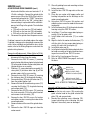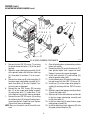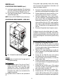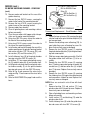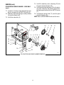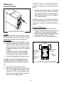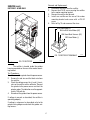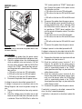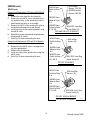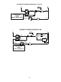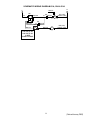
1
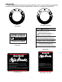
BUNN
®
G1,G2
& G3
STO
er.
pp
ho y.
the the tra
to
ws.
s in g on
g slo .
d. bean e ba
grin ffee st th
ensinically
disptomat
siredur co e. Re
as
e de po ut
es op au
t th d e ch
lec lid an r th itch. few timill st
1. Seft theg unde t sw er a der w
in
Li
ar
lev
ba
st
gr
2. ip
g e
the in
3. Sl ess clean g. Th
ba
e
4. Prp th e the
5. Fli mov
6. Re
TO
M
IC
AT
DRIP
FINE
E
ESS
O
R
C
U
SPR
A
P
SH
KI
REG
PER
C
EL
EC
P
E
R
TU
SPE
ING
AN
CLE
CIA
L
R
VE
LE
ND
OU E
GRFFE
CO
P
STO
er.
hopp y.
the the tra
to
ws.
s in g on
g slo .
d. bean ba
grin ffee st the
ensinically
disptomat
siredur co e. Re
as
e de po ut
es op au
t th d e ch
lec lid an r th itch. few timill st
Se
w
e
de
a
r
th
1. ft g un t sw er de
in
2. Li ip ba e staring lev e gr
th
3. Sl ess clean g. Th
ba
e
4. Prp th e the
5. Fli mov
FINE
DRIP
6. Re
TIC
TO
M
A
E
ESS
O
R
C
U
SPR
A
SH
KI
REG
PER
C
EL
EC
P
E
R
TU
SPE
G
IN
AN
CLE
CIA
L
R
VE
LE
ND
OU E
GRFFE
CO
OPERATING & SERVICE MANUAL
BUNN-O-MATIC CORPORATION
POST OFFICE BOX 3227
SPRINGFIELD, ILLINOIS 62708-3227
PHONE: (217) 529-6601 FAX: (217) 529-6644
10191.0000Q 1/00 ©1995 Bunn-O-Matic Corporation
INTRODUCTION
This equipment will grind whole bean coffee to a user-selectable setting and dispense it into a bag. The
equipment is only for indoor use on a sturdy counter or shelf. Adequate space must be available above the
grinder to raise the lid when adding beans.
BUNN-O-MATIC COMMERCIAL GRINDER WARRANTY
Bunn-O-Matic Corp. (“Bunn”) warrants the equipment manufactured by it to be commercially free from
defects in material and workmanship existing at the time of manufacture and appearing within one year from the
date of installation. In addition, Bunn warrants that the grinding burrs will grind coffee to meet original factory
screen sieve analysis for three years from date of installation or for 30,000 pounds of coffee, whichever comes
first. This warranty does not apply to any equipment, component or part that was not manufactured by Bunn or
that, in Bunn’s judgement, has been affected by misuse, neglect, alteration, improper installation or operation,
improper maintenance or repair, damage or casualty.
THE FOREGOING WARRANTY IS EXCLUSIVE AND IS IN LIEU OF ANY OTHER WARRANTY, WRITTEN OR
ORAL, EXPRESS OR IMPLIED, INCLUDING, BUT NOT LIMITED TO, ANY IMPLIED WARRANTY OF EITHER MERCHANTABILITY OR FITNESS FOR A PARTICULAR PURPOSE. The agents, dealers or employees of Bunn are not
authorized to make modifications to this warranty or to make additional warranties that are binding on Bunn.
Accordingly, statements by such individuals, whether oral or written, do not constitute warranties and should not
be relied upon.
The Buyer shall give Bunn prompt notice of any claim to be made under this warranty by telephone at (217)
529-6601 or by writing to Post Office Box 3227, Springfield, Illinois, 62708-3227. If requested by Bunn, the
Buyer shall ship the defective equipment prepaid to an authorized Bunn service location. If Bunn determines, in
its sole discretion, that the equipment does not conform to the warranty, Bunn shall repair the equipment with no
charge for parts during the one year warranty period and no charge for labor by a Bunn Authorized Service
Representative during the one year warranty period. If Bunn determines that repair is not feasible, Bunn shall, at
its sole option, replace the equipment or refund the purchase price for the equipment.
THE BUYER’S REMEDY AGAINST BUNN FOR THE BREACH OF ANY OBLIGATION ARISING OUT OF THE
SALE OF THIS EQUIPMENT, WHETHER DERIVED FROM WARRANTY OR OTHERWISE, SHALL BE LIMITED, AS
SPECIFIED HEREIN, TO REPAIR OR, AT BUNN’S SOLE OPTION, REPLACEMENT OR REFUND. Bunn shall not be
liable for any other damage or loss, including, but not limited to, lost profits, lost sales, loss of use of equipment,
claims of Buyer’s customers, cost of capital, cost of down time, cost of substitute equipment, facilities or services, or any other special, incidental or consequential damages.
2
USER NOTICES
Carefully read and follow all notices on the grinder and in this manual. They were written for your protection.
All notices on the grinder are to be kept in good condition. Replace any unreadable or damaged labels.
C
P
FI
NE
EL
E
M AT I C D R I P
AU TO
C
ER
ES
ESS
PER
C
PR
REG
O
SH
TURKI
SPECIAL
11075.0004 (SPECIAL)
11075.0000
WARNING
Use only on a properly protected circuit
capable of the rated load.
Electrically ground the chassis.
Follow national/local electrical codes.
Do not use near combustibles.
PLEASE CLOSE LID
BEFORE GRINDING
PERSONAL INJURY HAZARD
Keep Fingers & Foreign Objects
out of Hopper or Chute Opening
An extension cord, when used, must be shorter
than 20 feet if 16-gage 3-conductor wire, or
shorter than 10 feet if 18-gage 3-conductor wire.
PLEASE DO NOT POUR GROUND
COFFEE BACK INTO GRINDER
FAILURE TO COMPLY RISKS EQUIPMENT
DAMAGE, FIRE, OR SHOCK HAZARD
!
CAUTION
READ THE ENTIRE OPERATING MANUAL
INCLUDING THE LIMIT OF WARRANTY AND
LIABILITY BEFORE BUYING OR USING THIS PRODUCT
11076.0000
20545-0000 7/90 © 1990 Bunn-O-Matic Corporation
20545.0000
1. Select the desired grind.
2. Lift the lid and pour coffee beans into the hopper.
3. Slip bag under the chute. Rest the bag on the tray.
4. Press the start switch.
5. Flip the cleaning lever a few times as dispensing slows.
6. Remove the bag. The grinder will stop automatically.
1. Select the desired grind.
2. Lift the lid and pour coffee beans into the hopper.
3. Slip bag under the chute. Rest the bag on the tray.
4. Press the start switch.
5. Flip the cleaning lever a few times as dispensing slows.
6. Remove the bag. The grinder will stop automatically.
25152.0000 - G1
25153.0000 - G2 & G3
3
ELECTRICAL REQUIREMENTS
The 120 volt and 240 volt grinders have an attached cordset and requires 2-wire, grounded service rated 120
volts ac and 240 volts ac, 15 amp, single phase, 60 Hz. The 230 volt grinders have a power connector and
requires 2-wire, grounded service rated 230 volts ac, 15 amp, single phase, 50 Hz.
INITIAL SET-UP
CAUTION - Unplug the grinder throughout the initial set-up.
1.
2.
3.
4.
5.
6.
7.
8.
Open the top lid. Clear all foreign objects and shipping materials from the hopper compartment and the
entrance to the grind chamber.
Tip the machine gently, on its back, so it rests with approximately one inch of the bottom overhanging the
work surface.
Remove the drawer from the base assembly.
Place the base against the grinder bottom and align the four sets of holes.
Securely fasten the base to the grinder bottom using the four screws and washers provided.
Raise the grinder to the upright position.
Insert the drawer into the base assembly.
The grinder can now be plugged-in and put into service.
OPERATING CONTROLS
Off/On/Start Switch
OFF - (upper position)
Switching to this position stops the operation of the grinder.
ON - (center, resting position)
The switch will return to this position after a grind cycle has begun and will remain in this position after grinding
has ceased.
START - (lower, momentary position)
Pressing the switch initiates grinding only when a bag is in place behind the chute.
Grind Selector
Allows the user to vary the grind for each bag of coffee. Each setting will provide precisely the same grind every
time it is selected.
Bag Sensor
Prevents the grinder from operating unless the back of a bag is in place behind the dispense chute.
Do not attempt to bypass this safety device.
CLEANING
The use of a damp cloth rinsed in any mild, non-abrasive, liquid detergent is recommended for cleaning all
surfaces on Bunn-O-Matic equipment. Regular cleaning will keep your grinder looking new for years
4
COFFEE GRINDING
1.
2.
3.
Turn the selector knob to align the red arrow with the desired grind.
Raise the top lid and add the whole bean coffee. Close the top lid.
Locate the back of a bag behind the dispense chute. (The grinder will not operate unless the bag is
behind the chute.)
4. Allow the bag to rest on the screen beneath the chute.
5. Press the start switch.
6. Flip the cleaning lever a few times as dispensing slows.
7. Remove the bag when ground coffee is no longer dispensed from the chute. The grinder will stop
automatically as the bag is removed.
NOTE - The start switch will have to be pressed again to continue the cycle if the bag is removed while
grinding.
ADJUSTMENT
1.
2.
3.
4.
Place an empty bag on the screen, with the back of the bag behind the dispense chute.
Start the grinder to clear the grind chamber. Leave grinder “ON”.
Turn the Grind Selector knob to the “TURKISH” (fully clockwise) position.
Using a small flat blade screwdriver, loosen the two set screws on the left side of the grind selector
knob.
5. Hold the knob in the “TURKISH” (fully clockwise) position with one hand.
6. Using a large flat blade screwdriver, slowly turn the adjusting screw in the center of the grind selector
knob to the right (clockwise) until a metallic whine can be heard due to the rubbing of the grinding burrs.
7. While holding the knob in the “TURKISH” (fully clockwise) position, back off the screw to the left (counterclockwise) just until the metallic whine ceases.
8. Turn-off the grinder.
9. Push the knob against the dial plate and tighten both set screws on the left side of the grind selector
knob.
10. Turn the grinder on and listen again for the metallic whine with the grind selector knob in the turkish
(fully clockwise) position. If the metallic whine is heard, repeat steps 7 through 10 until the sound
ceases.
11. If no metallic whine is heard, the grinding burrs are adjusted properly.
5
TROUBLESHOOTING
A troubleshooting guide is provided to suggest probable causes and remedies for the most likely problems
encountered. If the problem remains after exhausting the troubleshooting steps, contact the Bunn-O-Matic
Technical Service Department.
•
Inspection, testing, and repair of electrical equipment should be performed only by qualified service personnel.
WARNING – • Exercise extreme caution when servicing electrical equipment.
• Disconnect the grinder from the power source when servicing, except when electrical tests
are specified.
• Follow recommended service procedures
• Replace all protective shields or safety notices
PROBLEM
PROBABLE CAUSE
REMEDY
Grinder will not start.
1. No power or incorrect voltage.
(A) Plug-in the grinder.
(B) Check the voltage at the wall
outlet with a voltmeter. It must be
120 volts ac for two wire 120 volt
models or 230 volts ac for two wire
230 volt 50 Hz models or 240 volts
ac for two wire 240 volt 60 Hz
models.
2. Off/On/Start Switch.
(A) Press the switch to the
“START” position.
(B) Refer to Service - Off/On/Start
Switch for testing procedures. See
page 16.
3. Bag sensor.
(A) The receiving bag must be
placed on the tray screen and have
the back of the bag behind the dispense chute to activate the sensor
switch.
6
TROUBLESHOOTING (cont.)
PROBLEM
PROBABLE CAUSE
REMEDY
Grinder will not start. (cont.)
3. Bag Sensor. (cont.)
(B) Refer to Service - Bag Sensor
Switch for testing and adjustment
procedures. See page 9.
4. Motor overload protector.
Remove the plug located on the
right side of the housing. Press the
red “Reset” button visible through
the opening. Listen carefully for a
“click”. This resets the motor protection circuit and may indicate
that an overload has been encountered by the motor. (An overload
can occur when something other
than coffee is inserted into the
hopper for grinding. Refer to Service - Motor for disassembly.) See
page 10 for AC Motors or see page
13 for DC Motors.
1. Off/On/Start Switch
(A) Move the switch to the “OFF”
position.
Grinder will not shut off.
(B) Refer to Service - Off/On/Start
Switch for testing procedures. See
page 16.
2. Bag Sensor
(A) Remove bag from under the
dispense chute.
(B) Refer to Service - Bag Sensor
Switch for testing procedures. See
page 9.
3. Relay
Refer to Service - Relay for testing procedures. See page 18.
7
TROUBLESHOOTING (cont.)
PROBLEM
PROBABLE CAUSE
REMEDY
Grinder starts, but will not dispense.
1. Hopper
Coffee must be poured into hopper
before grinding.
2. Entrance to grind chamber
Foreign materials must not block the
opening at the bottom of the hopper.
3.Shear Plate
Remove both black fillister head
screws holding the grinder selector
dial plate to the grinder. Carefully
remove the dial plate and rotor cup.
Inspect the shear plate for wear.
Replace if excessively worn or damaged.
8
BAG SENSOR SWITCH
SERVICE
This section provides procedures for testing and
replacing various major components used in this
grinder should service become necessary. Refer to
Troubleshooting for assistance in determining the
cause of any problem.
COMPONENT ACCESS
STO
er.
hopp y.
the the tra
to
ws.
s in g on
g slo .
d. bean e ba
grin ffee st th
ensinically
disptomat
siredur co e. Re
as
e de po ut
es op au
t th d e ch
st
lec lid an r th itch. few tim
will
1. Seft theg unde t sw er a der
in
Li
ar
2. ip ba e st ng lev e gr
th
3. Sl ess cleani g. Th
Pr the e ba
4. p e th
5. Fli mov
FINE
DRIP
6. Re
TIC
TO
M
A
E
O
R
C
U
ESS
A
SPR
WARNING - Unplug the grinder before the removal of
any panel or the replacement of any component.
P
KI
SH
EL
EC
P
E
R
TU
REG
PER
C
All components are accessible by the removal of
the top lid, hopper, and rear panel.
SPE
ING
AN
CLE
The top lid is attached with two #6-32 screws, the
hopper assembly is attached with four #6-32 screws
and the rear panel is attached with ten #8-32 screws.
CIA
L
R
VE
LE
ND
OU E
GRFFE
CO
CONTENTS
Bag Sensor Switch ............................................ 9
Motor and Grind Chamber (AC) ....................... 10
Motor and Grind Chamber (DC) ....................... 13
Off/On/Start Switch .......................................... 16
Rectifier ........................................................... 17
Relay................................................................ 18
Wiring Diagrams ......................................... 20,21
FIG. 2 BAG SENSOR SWITCH
P1704
Location:
The bag sensor switch is located inside the lower
front of the grinder housing behind the coffee dispensing chute.
Test Procedure:
1. Disconnect the grinder and place a coffee bag
behind the dispense chute.
2. Remove the white/violet wire from the bag sensor switch.
3. Check the voltage across the white/violet wire
from the bag sensor switch and the white wire,
red/black wire or red wire on the relay coil with a
voltmeter. Hold the Off/On/Start switch in the
“START” (lower) position and connect the grinder
to the power source. The indication must be:
a. 120 volts ac for two wire 120 volt models.
b. 230 volts ac for two wire 230 volt models.
c. 240 volts ac for two wire 240 volt models.
4. Disconnect the grinder from the power source.
P
STO
er.
hopp y.
the the tra
to
ws.
s in g on
g slo .
d. bean e ba
grin ffee st th
ensinically
disptomat
siredur co e. Re
as
e de po ut
es op au
t th d e ch
lec lid an r th itch. few timill st
Se
w
e
de
a
r
th
1. ft g un t sw er de
in
2. Li ip ba e staring lev e gr
th
3. Sl ess clean g. Th
ba
e
4. Prp th e the
5. Fli mov
FINE
DRIP
6. Re
TIC
TO
M
A
E
ESS
U
SPR
O
A
SH
C
R
KI
REG
PER
C
EL
EC
P
E
R
TU
SPE
CIA
L
ER
V
ING
LE
AN
CLE
ND
OU E
GRFFE
CO
FIG. 1 COMPONENT ACCESS
P1724
9
AC MOTOR AND GRIND CHAMBER
SERVICE (cont,)
BAG SENSOR SWITCH (cont.)
If voltage is present as described, proceed to
#5.
If voltage is not present as described, refer to
the Wiring Diagrams and check the grinder wiring harness.
STO
TO
M
A
E
O
R
C
U
ESS
A
SPR
Check for continuity across the terminals on the
bag sensor switch.
P
KI
SH
P
E
R
TU
REG
PER
C
EL
EC
5.
er.
hopp y.
the the tra
to
ws.
s in g on
g slo .
d. bean e ba
grin ffee st th
ensinically
disptomat
siredur co e. Re
as
e de po ut
es op au
t th d e ch
lec lid an r th itch. few timill st
1. Seft theg unde t sw er a der w
in
2. Li ip ba e staring lev e gr
th
3. Sl ess clean g. Th
ba
e
4. Prp th e the
5. Fli mov
FINE
DRIP
6. Re
TIC
If continuity is present as described, reconnect the
wires, the switch is operating properly.
If continuity is not present as described, replace the
switch.
SPE
ING
L
AN
CLE
ND
OU E
GRFFE
CO
Removal and Replacement:
1. Remove the wires from the switch.
2. Remove the two #8-32 keps nuts securing the
bag sensor assembly to the grinder housing.
3. Remove the two #2-56 screws, nuts and external tooth lockwashers securing the switch to the
bag sensor assembly.
4. Mount the new switch to the bag sensor assembly using two #2-56 screws, nuts and external
tooth lockwashers. Adjust the assembly by locating the corner of the switch housing to the
top edge of the black metal mounting bracket.
5. Reattach the sensor assembly to the grinder
housing and secure with two #8-32 keps nuts.
6. Refer to Fig. 3 when reconnecting the wires.
P1704
FIG. 4 AC MOTOR AND GRIND CHAMBER
Location:
The motor is located inside the upper part of the
grinder housing.
Test Procedure:
1. Remove the plug located on the right side of the
housing. Press the red “Reset” button visible
through the opening. Listen carefully for a “click”.
This resets the motor protection circuit and may
indicate that something other than coffee was
inserted into the hopper for grinding.
WHI/VIO from
Off/On/Start
Switch
WHI/ORA to
Terminal “A”
on Relay
FIG. 3 BAG SENSOR SWITCH TERMINALS
CIA
R
VE
LE
If the grinder remains unable to start, proceed to #2.
If the grinder stops operating shortly after starting,
refer to removal and replacement instructions and inspect for foreign materials.
2.
P1705
3.
4.
10
Disconnect the grinder from the power source
and place a coffee bag behind the dispense chute.
Remove the electrical access panel at the rear of
the motor.
Check the voltage across the white, red or red/
11. Clean all grinding burrs and mounting surfaces
before reassembly.
12. Install the four .250"-20 cage nuts on the new
motor.
13. Place the new motor with hopper collar and
bushing into position on the bushings on the
motor mounting bracket.
14. Using four .250"-20 screws, flat washers and
rubber washers secure the motor to the mounting bracket.
15. Install stationary burr (9) to the grind chamber
housing using two .250"-20 screws.
16. Install burr (7) and burr auger rotor/spring assembly (3) on to motor shaft.
17. Install motor shaft extension (11) on motor
shaft.
18. Align the slot in the motor shaft extension (11)
with the slot in the burr auger rotor/spring assembly (6) and install shear plate (4).
19. Install burr rotor cup (5).
20. Install grind selector dial plate and grind selector knob assembly on the grind chamber housing and secure with two .250"-20 screws.
21. Refer to Fig. 5 and reconnect the wires.
22. Refer to ADJUSTMENTS on page 5 and reset
the burrs.
SERVICE (cont,)
AC MOTOR AND GRIND CHAMBER (cont.)
5.
black and white/blue wires on terminals L1 &
L2 with a voltmeter. Connect the grinder to the
power source. When the Off/On/Start switch is
momentarily placed in the “START” (lower) position and then left in the “ON” (center) position and a bag is in place behind the coffee dispense chute.Plug-in the grinder. The indication
must be:
a. 120 volts ac for two wire 120 volt models.
b. 230 volts ac for two wire 230 volt models
c. 240 volts ac for two wire 240 volt models.
Disconnect the grinder from the power source.
If voltage is present as described replace the motor.
If voltage is not present as described, reconnect the
white, red or red/black and white/blue wires to the
motor, refer to the Wiring Diagrams and check the
grinder wiring harness.
Removal and Replacement - Motor (Refer to FIG.6):
1. Remove the plate on the rear of the motor and
disconnect all wires from the motor.
2. Remove the two .250"-20 screws (1) securing
grind selector dial plate and grind selector knob
(2) to the grind chamber. Remove dial plate and
selector knob as an assembly.
3. Slide burr (7), auger rotor/spring assembly (3),
shear plate (4) and burr rotor cup (5) off the
grinder motor shaft as an assembly.
4. Remove the two .250"-20 screws (8) securing
the stationary burr (9) to the grind chamber.
5. Remove bushing (10) and shaft extension (11)
from the grinder motor shaft.
6. Remove the two #8 thread forming screws (12)
securing the fill plate (13) to grinder housing
and remove plate (13).
7. Remove the four #10-24 screws (14) securing
the chute assembly (15) to the grind chamber
and remove chute assembly (15).
8. Remove the four .250"-20 screws, flat washer
and rubber washers securing the motor to the
mounting bracket.
9. Remove motor out the rear of the grinder housing.
10. Remove the four .250"-20 cage nuts from the
motor mount.
WHI/BLU to
Relay N.O.(K4)
WHI to Cordset (120V)
RED/BLK to Cordset (230V)
GRN to Ground (120V)
GRN/YEL to Ground (230V)
FIG. 5 AC MOTOR TERMINALS
P1310
Removal and Replacement - Grind Chamber - Refer
to Fig. 6:
1. Loosen the two set screws (16) securing the
grind selector knob to the grind selector dial
plate (18) and remove knob.
2. Remove the adjusting screw w/bearing (19).
Inspect adjusting screw w/bearing for wear.
Replace if excessively worn or damaged.
11
SERVICE (cont.)
AC MOTOR AND GRIND CHAMBER (cont.)
18 1 19 17
P
STO
er.
hopp y.
the the tra
to
ws.
s in g on
g slo .
d. bean e ba
grin ffee st th
ensinically
disptomat
siredur co e. Re
as
e de d po chut
es op au
t th
e
lec lid an r th itch. few timill st
1. Seft theg unde t sw er a der w
in
Li
ar
lev
ba
st g e gr
2. ip
the in
3. Sl ess clean g. Th
ba
e
4. Prp th e the
5. Fli mov
6. Re
20 7 6 4
5
11 10 9 8
3
R
KI
SH
TU
SPE
CIA
L
2
14
U
TO
M
16
E
O
A
1
FINE
ESS
LE
DRIP
SPR
R
VE
ING
AN
IC
AT
CLE
C
R
KI
SH
R
TU
EL
EC
P
E
15
PER
C
13
REG
ND
OU E
GRFFE
CO
7
SPE
CIA
L
12
FIG. 6 GRIND CHAMBER COMPONENTS
3.
Remove the two .250"-20 screws (1) securing
the grind selector dial plate (18) to the grind
housing.
4. Slide burr auger rotor/spring assembly (3) off
of the grinder motor shaft with burr rotor cup
(5), shear plate (4) and burr (7) as an assembly.
5. Remove burr rotor cup (5) and shear plate (4)
from burr auger rotor/spring assembly (6). Inspect shear plate (4) for wear. Replace if excessively worn or damaged.
6. Remove the two .250" screws (20) securing
burr (7) to burr auger rotor/spring assembly
(6) and remove burr (7). Inspect burr (7) for
wear. Replace if excessively worn or damaged.
7. Remove the two .250"-20 screws (8) securing
the stationary burr (9) to grind chamber housing and remove burr. Inspect for wear. Replace
if excessively worn or damaged.
NOTE: Burrs are serviced in sets of two with hardware.
8.
9.
10.
11.
12.
13.
14.
15.
16.
12
P1708
Clean all grinding burrs and mounting surfaces
before reassembly.
Remove bushing (10) and shaft extension (11)
from grinder motor shaft. Inspect for wear.
Replace if excessively worn or damaged.
Install shaft extension (11) and bushing (10)
onto the grinder motor shaft.
Install stationary burr (9) inside the grind chamber and secure with two .250" -20 screws (8).
Install burr (7) on burr auger rotor/spring assembly (6) securing with two .250"-20 screws
(20).
Slide burr auger rotor/spring assembly and burr
(3) onto the motor shaft.
Align the slot in the shaft extension and the slot
in the burr auger rotor/spring assembly and
install shear plate (4).
Install burr rotor cup (5) onto the burr auger
rotor/spring assembly (6).
Install the adjusting screw w/bearing (19) into
the grind selector dial plate (18).
If the grinder stops operating shortly after starting,
refer to removal and replacement instructions and
inspect for foreign materials.
SERVICE (cont.)
AC MOTOR AND GRIND CHAMBER (cont.)
17. Install grind selector dial plate (18) with adjusting screw w/bearing (19) onto the grind chamber and secure with two .250"-20 screws (1).
18. Install grind selector knob (17) onto the grind
selector dial plate (18).
NOTE: Refer to ADJUSTMENTS and reset the burrs.
2.
3.
4.
DC MOTOR AND GRIND CHAMBER - G1MD ONLY
5.
STO
er.
hopp y.
the the tra
to
ws.
s in g on
g slo .
d. bean e ba
grin ffee st th
ensinically
disptomat
siredur co e. Re
as
e de po ut
es op au
t th d e ch
lec lid an r th itch. few timill st
Se
w
e
de
1. ft th g un t sw er a der
in
2. Li ip ba e staring lev e gr
th
3. Sl ess clean g. Th
ba
e
4. Prp th e the
5. Fli mov
FINE
DRIP
6. Re
TIC
TO
M
A
E
ESS
U
If voltage is present as described replace the motor.
If voltage is not present as described, reconnect the
white or red and white/blue wires to the motor, refer
to the Wiring Diagrams and check the grinder wiring
harness.
SPR
O
A
P
SH
C
R
KI
REG
PER
C
EL
EC
P
E
R
TU
SPE
ING
AN
CLE
CIA
Disconnect the grinder from the power source
and place a coffee bag behind the dispense chute.
Remove the black wire from the rectifier (+) terminal and the red wire from the (-) terminal.
Check the voltage across the (+) and (-) terminals with a voltmeter. Connect the grinder to the
power source. When the Off/On/Start switch is
momentarily placed in the “START” (lower) position and then left in the “ON” (center) position
and a bag is in place behind the coffee dispense
chute. The indication must be approximately 108
volts dc.
Disconnect the grinder from the power source.
L
R
VE
LE
ND
OU E
GRFFE
CO
Removal and Replacement - Motor (Refer to Fig. 9)
1. Disconnect all wires from the motor.
2. Remove the two .250"-20 screws (1) securing
grind selector dial plate and grind selector knob
(2) to the grind chamber. Remove dial plate and
selector knob as an assembly.
3. Slide burr (7), auger rotor/spring assembly (3)
and burr rotor disc (4) off the grinder motor shaft
as an assembly.
4. Remove the two .250"-20 screws (8) securing
the stationary burr (9) to the grind chamber.
5. Remove bushing (10) and washer (11) from the
grinder motor shaft.
6. Remove the two #8 thread forming screws (12)
securing the fill plate (13) to grinder housing and
remove plate (13).
7. Remove the four #10-24 screws (14) securing
the chute assembly (15) to the grind chamber
and remove chute assembly (15).
8. Disconnect all the wires from the rectifier (23).
9. Remove the four .312"-18 screws (20), rubber
washers (22) and flat washers (21) securing the
motor and bracket to the grinder housing bracket.
P1706
FIG. 7 DC MOTOR AND GRIND CHAMBER
Location:
The motor is located inside the upper part of
the grinder housing.
Test Procedures:
1. Remove the rear panel. Press the red “Reset”
button visible on the rear of the motor. Listen
carefully for a “click”. This resets the motor
protection circuit and may indicate that something other than coffee was inserted into the
hopper for grinding.
If the grinder remains unable to start, proceed to
#2.
13
SERVICE (cont,)
BLU to BLU from Rectifier
BLU to WHI/BLU from
Relay (3)
RED to Rectifier (-)
BLK to Rectifier (+)
DC MOTOR AND GRIND CHAMBER - G1MD ONLY
(cont.)
10. Remove motor and bracket out the rear of the
grinder housing.
11. Remove the two .250"-20 screws securing the
motor to the front of the mounting bracket.
12. Remove the two #10-32 screws securing the
motor to rear of the mounting bracket.
13 Remove motor from bracket.
14. Clean all grinding burrs and mounting surfaces
before reassembly.
15 Place the new motor with hopper collar into position on the motor mounting bracket.
16. Using two .250"-20 screws secure the motor to
the front of the mounting bracket.
17. Using two #10-32 screws secure the motor to
the rear of the mounting bracket
18. Install motor and bracket through the rear of the
grinder, position on the grinder housing bracket
and secure with four .312"-18 screws (20), rubber washers (22) and flat washers (21).
19. Install stationary burr (9) to the grind chamber
housing using two .250"-20 screws (8).
20. Install burr (7), burr auger rotor/spring assembly (3) and burr rotor disc (4) on to motor shaft.
21. Install grind selector dial plate and grind selector knob assembly (2) on the grind chamber
housing and secure with two .250"-20 screws.
22. Refer to Fig. 8 and reconnect the wires to the
motor and Fig. 13 and reconnect the wires to the
rectifier.
23. Refer to ADJUSTMENTS on page 5 and reset the
burrs.
P1710
FIG. 8 DC MOTOR TERMINALS
Removal and Replacement - Grind Chamber - Refer
to Fig. 9:
1. Loosen the two set screws (16) securing the grind
selector knob to the grind selector dial plate (18)
and remove knob.
2. Remove the adjusting screw w/bearing (19). Inspect adjusting screw w/bearing for wear. Replace if excessively worn or damaged.
3. Remove the two .250"-20 screws (1) securing
the grind selector dial plate (18) to the grind housing and remove plate.
4. Slide burr auger rotor/spring assembly (3) off of
the grinder motor shaft with burr (7) as an assembly.
5. Remove the two .250"-20 screws (5) securing
burr (7) to burr auger rotor/spring assembly (6),
remove burr (7) and burr rotor disc (4). Inspect
burr (7) for wear. Replace if excessively worn or
damaged.
6. Remove the two .250"-20 screws (8) securing
the stationary burr (9) to grind chamber housing
and remove burr. Inspect for wear. Replace if excessively worn or damaged.
NOTE: Burrs are serviced in sets of two with hardware.
7. Remove bushing (10) and washer (11) from
grinder motor shaft. Inspect for wear. Replace if
excessively worn or damaged.
8. Clean all grinding burrs and mounting surfaces
before reassembly.
9. Install washer (11) and bushing (10) onto the
grinder motor shaft.
10. Install stationary burr (9) inside the grind chamber and secure with two .250" -20 screws (8).
14
14. Install the adjusting screw w/bearing (19) into
the grind selector dial plate (18).
15. Install grind selector dial plate (18) with adjusting screw w/bearing (19) onto the grind chamber housing and secure with two .250"-20 screws
(1).
16. Install grind selector knob (17) onto the grind
selector dial plate (18).
NOTE: Refer to ADJUSTMENTS and reset the burrs.
SERVICE (cont,)
DC MOTOR AND GRIND CHAMBER - G1MD ONLY
(cont.)
11. Install burr (7) on burr auger rotor/spring assembly (6) securing with two .250"-20 screws (5).
12. Slide burr auger rotor/spring assembly and burr
(3) onto the motor shaft.
13. Install burr rotor disc (4).
18
6
M
IC
AT
DRIP
FINE
E
O
SH
EL
EC
P
E
R
C
KI
R
TU
REG
PER
C
7
TO
17
ESS
5
U
19
SPR
A
1
P
STO
er.
hopp y.
the the tra
to
ws.
s in g on
g slo .
d. bean ba
grin ffee st the
ensinically
disptomat
siredur co e. Re
as
e de po ut
es op au
t th d e ch
lec lid an r th itch. few timill st
1. Seft theg unde t sw er a der w
in
2. Li ip ba e staring lev e gr
th
3. Sl ess clean g. Th
ba
e
Pr
4. p th e the
5. Fli mov
6. Re
23
SPE
9
CIA
L
8 11 10 3
22
4
21
16
U
TO
M
E
O
A
FINE
ESS
7
DRIP
SPR
SH
P
E
R
C
KI
R
TU
EC
ND
OU E
GRFFE
CO
IC
AT
13
12
EL
R
VE
LE
C
ING
AN
CLE
PER
14
15
1
REG
20
2
SPE
CIA
L
P1711
FIG. 9 MOTOR AND GRIND CHAMBER REMOVAL
15
If continuity is present as described, proceed to #6.
If continuity is not present as described, replace the
switch.
SERVICE (cont,)
OFF/ON/ START SWITCH
6.
STO
er.
hopp y.
the the tra
s.
to
s in g on
slow
d. bean e ba
ng ly.
th
grin e
ensi ical
red coffe Rest
disptomat
as
desi ur ute.
es op au
the d poe ch
lect lid an r th itch. few timill st
1. Seft theg unde t sw r a der w
ve
in
2. Li ip ba e starng le e gr
th
3. Sl ess cleani g. Th
ba
e
Pr
e
4. ip th e th
5. Fl mov
FINE
DRIP
6. Re
TIC
TO
M
A
If continuity is present as described, the Off/On/Start
switch is operating properly, reconnect the four wires.
If continuity is not present as described, replace the
switch.
E
ESS
U
P
SPR
O
A
C
R
KIS
H
REG
PER
C
EL
EC
P
E
R
TU
SPE
CIA
Check for continuity across the two 3/16" terminals when the switch is held in the “START”
(lower) position. Continuity must not be present
across these terminals in the “OFF” (upper) or
“ON” (center) positions.
L
R
VE
ING
LE
AN
CLE
Removal and Replacement:
1. Remove all wires from the switch terminals.
2. Compress the clips inside the front wrapper and
gently push the switch through the opening.
3. Push the new switch into the opening and spread
the clips to hold the switch in the hood.
4. Refer to Fig. 11 when reconnecting the wires.
ND
OU E
GRFFE
CO
FIG.10 OFF/ON/START SWITCH
P1724
Location:
The Off/On/Start switch is located in the upper front wrapper above and to the right of the grind
selector knob (left side when viewed from rear).
Test Procedure:
1. Disconnect the grinder from the power source.
2. Check the voltage across the black wire on the
Off/On/Start switch and the white wire or the red/
black on the relay coil with a voltmeter. Connect
the grinder to the power source. The indication
must be:
a. 120 volts ac for two wire 120 volt models.
b. 230 volts ac for two wire 230 volt models.
c. 240 volts ac for two wire 240 volt models.
3. Disconnect the grinder from the power source.
WHI/RED
WHI/VIO to
Bag Sensor
Switch
BLK to
Cordset
WHI/VIO to
Relay 6
If voltage is present as described, proceed to #4.
If voltage is not present as described, refer to the
Wiring Diagrams and check the grinder wiring harness.
4.
5.
WHI/RED to
Relay 7
P606
FIG. 11 OFF/ON/START SWITCH TERMINALS
Remove all four wires from the switch.
Check for continuity across the two 1/4" terminals when the switch is held in both the “ON”
(center) and “START” (lower) positions. Continuity must not be present across these terminals in the “OFF” (upper) position.
16
Removal and Replacement:
1. Disconnect the wires from the rectifier.
2. Remove the #10-32 screw securing the rectifier
to the motor mounting bracket.
3. Remove the rectifier and discard.
4. Install new rectifier on the rear of the motor
mounting bracket and secure with a #10-32
screw.
5. Refer to Fig. 13 and reconnect the wires.
SERVICE (cont.)
RECTIFIER - G1MD ONLY
P
STO
er.
hopp y.
the the tra
to
ws.
s in g on
g slo .
d. bean e ba
grin ffee st th
ensinically
disptomat
siredur co e. Re
as
e de po ut
es op au
t th d e ch
lec lid an r th itch. few timill st
Se
w
e
de
a
r
1. ft th g un t sw er de
in
Li
2. ip ba e staring lev e gr
th
3. Sl ess clean g. Th
ba
e
4. Prp th e the
5. Fli mov
FINE
DRIP
6. Re
TIC
TO
M
A
BLK from Motor (+)
BLU to BLU from Motor (AC)
E
ESS
U
SPR
O
A
SH
C
R
KI
PER
C
EL
EC
P
E
R
TU
REG
WHI from Main Harness (AC)
SPE
ING
AN
CIA
L
RED from Motor (-)
R
VE
LE
CLE
ND
OU E
GRFFE
CO
C
A
+
C
A
FIG. 13 RECTIFIER TERMINALS
Location:
FIG. 12 RECTIFIER
P1706
The rectifier is located inside the grinder
housing mounted on the rear of the motor mounting bracket.
Test Procedures:
1. Disconnect the grinder from the power source.
2. Remove the red wire and the black wire from
the rectifier.
3. Check the voltage across the (+) and (-) terminals on the rectifier with a voltmeter. Connect
the grinder to the power source and start the
grinder motor. The indication must be approximately 108 volts dc.
4. Disconnect the grinder from the power source.
If voltage is present as described, the rectifier is
operating properly.
If voltage is not present as described, refer to the
grinder wiring diagram and check the grinder wiring harness.
17
P1381
SERVICE (cont,)
RELAY
OP
ST
er.
pp
ho y.
the the tra
.
to
ws
s in g on
g slo .
d. bean e ba
grin ffee st th
ensinically
disptomat
siredur co e. Re
as
e de po ut
es op au
t th d e ch
lec lid an r th itch. few tim ll st
1. Seft theg unde t sw er a der wi
in
Li
ar
lev
2. ip ba e st ing e gr
th
3. Sl ess clean g. Th
ba
e
4. Prp th e the
5. Fli mov
FINE
DRIP
Re
6.
TIC
TO
M
A
E
ESS
O
R
C
U
SPR
A
KI
SH
C
EL
EC
P
E
R
TU
PER
6.
7.
REG
SPE
G
IN
AN
AN
CLE
CIA
L
R
VER
VE
LE
ND
OU E
GRFFE
CO
FIG.14 RELAY
P1704
P1704
8.
Location:
The relay is located on the grinder base inside
the lower housing.
“ON” (center) position or “START” (lower) position. Connect the grinder to the power source.
The indication must be:
a. 120 volts ac for two wire 120 volt models.
b. 230 volts ac for two wire 230 volt 50 Hz models.
c. 240 volts ac for two wire 240 volt 60 Hz models.
Disconnect the grinder from the power source.
Check the voltage across terminal B and the remaining white/red wire with a voltmeter. Place
the Off/On/Start switch in either the “ON” (center) position or “START (lower) position. Connect the grinder to the power source. The indication must be:
a. 120 volts ac for two wire 120 volt models.
b. 230 volts ac for two wire 230 volt 50 Hz models.
c. 240 volts ac for two wire 240 volt 60 Hz models.
Disconnect the grinder from the power source.
If voltage is present as described, proceed to #9.
If voltage is not present as described, refer to the Wiring Diagrams and check the grinder wiring harness.
Test Procedure:
1. Disconnect the grinder from the power source
and place a coffee bag behind the dispense chute.
2. Check the voltage across the white/orange and
white or red/black wires on terminals A & B of
the relay with a voltmeter. Hold the Off/On/Start
switch in the “START” (lower) position and connect the grinder to the power source. The indication must be:
a. 120 volts ac for two wire 120 volt models.
b. 230 volts ac for two wire 230 volt models.
c. 240 volts ac for two wire 240 volt models
3. Disconnect the grinder from the power source.
9.
Remove the white/violet wire from terminal 6 and
white/blue wire from terminal 4.
10. Check for continuity across terminals 7 & 4.
Connect the grinder to the power source.
Continuitymust be present when the Off/On/Start
switch is momentarily placed in the “START”
(lower) position and a bag is in place behind the
coffee dispense chute.
11. Check for continuity across terminals 9 & 6.
Connect the grinder to the power source. Continuity must be present when the Off/On/Start
switch is momentarily placed in the “START”
(lower) position and a bag is in place behind the
coffee dispense chute.
12. Disconnect the grinder from the power source.
If voltage is present as described, proceed to #4.
If voltage is not present as described, refer to the
Wiring Diagrams and check the grinder wiring harness.
4. Remove the white/red wires from relay contacts
7 & 9.
5. Check the voltage across the white wire or red/
black on terminal B and either white/red wire with
a voltmeter. Place the Off/On/Start in either the
If continuity is present as described, reconnect the
wires, the relay is operating properly.
If continuity is not present as described, replace the
relay.
18
SERVICE (cont,)
WHI/VIO from
Switch to Relay
K-6
RELAY (cont.)
Removal and Replacement (120 Volt and 240V 60 Hz
Models):
1. Remove the wires from the relay terminals.
2. Remove the two #6-32 screws securing the relay bracket w/relay to the grinder base and remove bracket and relay as an assembly.
4. Remove the #6-32 screw securing the relay to
the bracket and remove relay and discard.
5. Install new relay to the mounting bracket using
one #6-32 screw,
6. Mount the new relay w/bracket to the grinder base
using two #6-32 screws.
7. Refer Fig. 15 when reconnecting the wires.
WHI to Main
Harness 120V (B)
RED/BLK to Main
Harness 240V (B)
WHI/BLU from
Motor to Relay
K-4
WHI/RED from
WHI/ORN from Bag
Switch to Relay
Sensor Switch (A)
K-7 & K-9
120V AND 240 VOLT AC MODELS
WHI/VIO from
Switch to Relay
K-6
Removal and Replacement (230 volt 50 Hz Models):
1. Remove the wires from the relay terminals.
2. Remove the two #6-32 screws securing the relay to the grinder base.
4. Remove relay and discard.
5. Install new relay to the grinder base using two
#6-32 screw.
6. Refer Fig. 15 when reconnecting the wires.
WHI to Main
Harness (B)
WHI/BLU from
Motor to Relay
K-4
WHI/RED from
Switch to Relay
K-7 & K-9
WHI/ORN from Bag
Sensor Switch (A)
120 VOLT DC MODELS
WHI/VIO from
Switch to Relay
K-6
RED from Main
Harness (B)
WHI/BLU from
Motor to Relay
K-4
WHI/RED from
Switch to Relay
K-7 & K-9
WHI/ORN from Bag
Sensor Switch (A)
230 VOLT AC 50 Hz MODELS
FIG. 15 RELAY TERMINALS
19
P1707
(Revised January 2000)
SCHEMATIC WIRING DIAGRAM G1, G2 & G3
L1
N
GRN
SW1
WHI/RED K-7
BLK
WHI/BLU
L1
K-4
120 VOLT AC
2 WIRE
SINGLE PHASE 60 HZ
WHI
M
L2
WHI/VIO K-6
K-9
SW2
WHI/ORA
WHI/VIO
A
10190.0000F 9/91 © 1985 BUNN-O-MATIC CORPORATION
WHI
K
B
SCHEMATIC WIRING DIAGRAM G1-MD
L1
N
GRN
BLK
BLK
SW1
BLK
WHI/RED
K-7
BLU
BLU
M
BLU
BLU
K-4
RED
WHI/VIO K-6
K-9
SW2
WHI/VIO
- RECT +
WHI
WHI/ORA
A
120 VOLTS AC
2 WIRE
SINGLE PHASE 60 HZ
RED
WHI
K
B
10621.0000C 10/98 © 1992 BUNN-O-MATIC CORPORATION
20
SCHEMATIC WIRING DIAGRAM G1A, G2A & G3A
L1
L2
GRN/YEL
SW1
BLK
WHI/RED
WHI/VIO
WHI/VIO
K-7
N.O.
WHI/BLU
M
K-4
L1
N.O.
WHI/RED
K-6
K-9
SW2
WHI/ORA
230 VOLTS AC
240 VOLTS AC
2 WIRE
SINGLE PHASE
L2
RED (230V)
RED/BLK (240V)
K
A
RED (230V)
RED/BLK (240V)
B
10754.0000D 12/99 © 1993 BUNN-O-MATIC CORPORATION
21
(Revised January 2000)