1
$5
DLC SERIES
MS/IS-808
*
~~~~~INSTRUCTION
and
SERVICE MANUAL
C)
*
Clear-Comr
Intercom systems
1111 1 7th Street * San Francisco, California 941070 415-861-6666
CLEAR-COM 810003
808/9-84 REV D
CLEAR-COM
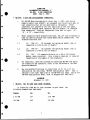
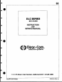
DOCUMENTATION ADDENDUM "C"
3S-808: 6-PIN CONNECTORS
DATE: JULY 1, 1987
*
MS-808:
6-PIN IFB/ISO/ACCESSORY CONNECTORS.
1.
All MS-808 Main Stations built after July 1, 1987, with serial
numbers higher than 6330407, are equipped with three 6-pin male XL
type connectors that are not mentioned in the manual. These
connectors are located on the left hand side of the rear panel,
between the Program Input connector and the channel 1-4 Intercom
Line connectors. They are designated, from left to right, "J3",
"J4", k "j5". respectively.
2.
These connectors have standard functions, but are also occasionally
used for special purpose and custom modification connections. The
standard functions are:
41
*
2.1
J3: "IFB 1-4". (J3 accesses the operating module that is
connected to J105 on the I/0 board.)
2.2
34: "IFB 5-8". (J4 accesses the operating module that is
connected to J106 on the I/O board.)
2.3
J5: "ISO". (J5 connects directly to a ISO-4 Iso Control
Module (when installed). Only a single connector is required
regardless of the number of ISO-4 modules.)
3.
For
3.
For additional, detailed information concerning MS-808 IFB and/or
ISO connection and operation, refer to the PIC-4000B or ISO-4000
Operation Manuals.
4.
Any non-standard functions or connections of J3, 34, & J5 are
indicated on the individual "MS-808 Configuration label" that is
affixed to the right hand side of the MS-808 rear panel, and on the
"MS-808 Configuration Sheet" that is shipped with each unit.
4*
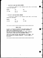
ADDENDUM
November 17, 1987
t
MS-808:
MIC TO LINE GAIN LEVEL INCREASE.
In effecting a 4dB Mic to Line increase in gain level, the
following changes have been made:
Change:
At:
To:
2.7K OHM
R37
3.9K OHM
10K OHM
R40
15K OHM
*
IFB-4 MIC TO LINE GAIN LEVEL INCREASE
In effecting a 4dB Mic to Line increase in gain level, the following
changes have been made:
Change:
At:
To:
4.7K OHM
R29, 31
6.8K OHM
@
33, 35
*
CH-4 MIC TO LINE GAIN LEVEL INCREASE
In effecting a 4dB Mic to Line increase in gain level, the following
changes have been made:
Change:
At:
To:
10K OHM
R37, 38,
39, 40
15K OHM
SPECIAL NOTE:
ON PAGE 13 OF THE MS-808 INSTRUCTION AND SERVICE MANUAL (PART
NUMBER 810003) UNDER THE SECTION "DLC SYSTEM INTERCONNECT",
DELETE THE THIRD SENTENCE WHICH READS:
With each DLC station, we supply two 30-pin female connectors
(these attach to each end of the interconnect cable)."
CLEAR-COM NO LONGER PROVIDES THESE CONNECTORS AT NO CHARGE. THEY
MUST BE ORDERED AND PURCHASED SEPARATELY. THE PART NUMBER IS:
DLC/82001 8.
2
4
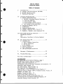
THE DLC SERIES
OPERATION MANUAL
Table of Contents
I.
Introduction
.
.
A. Circuit Flow Description (MS-808)
B. MS-808 Specifications
C Technical Overview
1
II.
Intercom System Set-Up .................... 7
A. System Interconnection
1. MS-808 & Standard Remote Stations... 7
1.1 Station Capacity
1.2 Interconnect Cable
1.3 Interconnection Procedures
2. DLC System Interconnection ......... 13
B- Assigning Channel I.D.'s
C- Termination
D. Program Send/Receive
E. Channel Sidetone Null ("A.S.T.")
F. Headsets, Speaker, and Gooseneck Mic
III. MS/IS-808 Operating Controls ............. 23
Unlabelled Button
ISO
Conversion from Mono to Stereo Headset
IV.
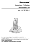
DLC System With IFB ...................... 35
A. Introduction
1. PIC-4 Program Controller
2. Talent Receivers
3. DLC System
B. System Connections
C. PIC-4 Operation
D. IFB System Specifications
V.
Warranty & Maintenance ................... 39
VI.
Trouble-Shooting ......................... 40
VII. Bill of Materials ........................ 43
ILLUSTRATIONS
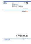
DLC Mainframe with Control Modules, page 2
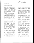
MS-808 Power Supply Capacity (graph), 7
Belden Cable Specifications, 9
Two-Channel Station Wiring, Permanent Installation, 10
Four-Pair Cable Detail, 12
DLC Interconnect Cable Wiring, 14
DLC Connector Pin Assignments, 15
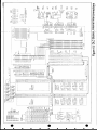
Input/Output ("I/O") Printed Circuit Board, 17
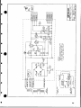
Intercom Control Module (CH-4) Printed Circuit Board, 18
Headset "Y" Cable, 22
Headset Extension Cable, 22
MS/IS Front Panel Controls, 24
Point-to-Point System Interconnection, 27
I/O Printed Circuit Board Stuffing Diagram, 29
Internal Wiring of DLC Station, 31
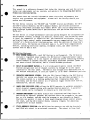
I.
0
INTRODUCTION
This manual is a reference document that helps the intercom user and the service
technician understand, set up, operate, and maintain the Clear-Com DLC Series
Production Intercom System.
This manual does not contain information about electrical adjustments that
require test procedures and equipment. Please call the factory should your
system need adjustment.
The DLC Series contains the "MS-808" and "IS-808" Station mainframes; the CH-4
and IFB-4 Control Modules; the SP-4 Speaker Module; and related accessories
including a Four-Wire Interface Unit (Model IF4-4) and a fully-integrated Program Interrupt System (Model PIC-4 IFB Controller and IFB Talent Receivers TR50/TR-62).
The DLC Series is a high-performance intercom system designed for teleproduction
and broadcast studios, although its features, versatility, and reliability make
it ideal for commercial or industrial use. Its innovative solid-state circuitry
and digital logic control enable programmable two-way communications in a "Party-Line" or a Point-to-Point intercom system. With the addition of Clear-Com's
interface units, the System can link with many 2, 3, and 4-wire communications
devices, including television cameras, telephone lines, and other intercom
systems such as RTS or Roh.
DLC Station Features:
1) FULL SYSTEM CAPABILITY-- each DLC Station is self-powered. The IS Station
contains a regulated power supply; the MS Station's regulated power supply
is slightly larger, so it can support an intercom system containing standard
remote headset or speaker stations. Each MS/IS mainframe provides "power on"
and short-circuit indication, and is circuit-breaker-protected.
2) BUILT-IN ASSIGNMENT MATRIX--a 9 x 10 slide-switch matrix inside the MS/IS
Station assigns each set of channel controls (A through H) to the inputs
connected to the rear panel. The Matrix also assigns your dedicated line to
the desired destination, or lets you "park" it in an "OFF" (disabled) position.
3) VERSATILE MONITORING SYSTEM-- With the CH-4 Control Module, the DLC Station
operator can access any channel with one of the two switches assigned to it.
The Listen control is a locking pushbutton that illuminates dimly when
activated, and the Talk control is a 3-position toggle switch with lock-on,
momentary-on, and off settings.
4) HANDS-FREE DEDICATED LINE--allows the MS/IS operator to maintain permanent,
point-to-point communications with another Station operator. A point-topoint system can be configured to contain up to nine stations.
5) PROGRAM MONITORING--the MS/IS Station has a balanced auxiliary input for
monitoring an external program; the operator hears the program in the speaker or in a headset, and may send the program to any channels so Remote
Stations can monitor it also. A front panel Program volume control adjusts
the level, and the CH-4 Control Module contains trimpots for adjusting
program level on each channel.
0
6)
STAGE ANNOUNCE FUNCTION--the MS/IS Station operator can add the Station's
amplified mic output to an external connector. The output is line-level
balanced, and works in conjunction with a "speaker mute" function provided
on the rear panel.
7)
VISUAL CALL SIGNALLING--attracts the attention of other Station operators;
also used to activate remote control of KB-112 Stations.
8)
ULTRA-STABLE SIDETONE CONTROL--suppresses feedback when using a mic and
speaker simultaneously
9)
MIC LIMITER-- part of the Station's mic preamplifier, the mic limiter prevents overload and maintains constant signal levels
10) GOOSENECK MIC--a noise-cancelling electret mic on an field-adjustable flexible extension is permanently attached to the MS/IS mainframe.
11)
EXTERNAL SPEAKER--the MS/IS Station provides a jack on the rear panel for
connecting the Station to an external speaker
Special DLC System Features:
1)
CHANNEL ISO-- allows the Station operator to hold a private conversation
with any channel(s) without having to turn off the "talk" monitor switches
for all other channels.
2)
OPTIONAL PROGRAM INTERRUPT (IFB) PACKAGE--includes the IFB-4 Control Module,
the PIC-4 Program Interrupt Controller, and one or more Talent Receivers,
for a fully-integrated IFB System with four channels of intercom and four
channels of IFB. Other combinations are possible. The DLC System is
available with up to eight intercom channnels and eight IFB channels.
3)
CAMERA INTERFACE--the IF4-4 Four-Wire Interface allows TV camerapeople (operating three-wire or four-wire systems) to communicate with Clear-Com
System operators
Interconnect Cable Required:
DLC Stations interconnect with 12-pair cable; the rear panel of each unit has
one or two 30-pin male connectors for output/input. This manual provides detailed diagrams to help the user construct the DLC interconnect cable, putting a
FEMALE 30-pin ("Tuchel" type) connector at each end.
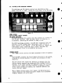
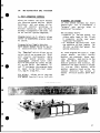
Figure 1
8 with one lF134 Module and one CH-4 Module
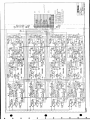
I.A. HS-808 CIRCUIT FLOW DESCRIPTION
The
MS/IS-808 Station circuitry
contains three major components:
the input/output ("I/O") board, the
four-channel intercom modules, and
the power supply.
*
The 1/0 board contains the microphone preamplifier, the power amplifier, bias supply circuits, and
the dedicated line monitoring circuit.
*
The
four-channel intercom board
(Model CH-4) contains four identical channel monitoring circuits,
each of which consists of switches
and logic that control, for each
channel:
--the monitoring of the talk/listen
circuits
--the DC "call" signalling
--the termination
--the program distribution
*
*
*
0
w
.
There are
two mic inputs to the
intercom station: one is the mic on
the headset, which is connected to
pins 1 and 2 on the station's front
panel headset connector;
it
is
input to the mic preamp (IC-IB) via
header J109.
The second input is
to the built-in electret gooseneck
mic, which is,
like the headset's
mic, mixed into the summing input
(pin 6) of IC-lB. The gooseneck mic
input
level is adjustable through
trimpot P5.
The electret mic
is
controlled
by
the mic
on/off
switch, which controls the power to
the gooseneck mic. The signal input
then goes through the mic preamp,
where it is amplified approximately
54 dB. The signal is controlled by
the limiter (Ql), which maintains
the output near 0 dB level.
The mic preamp output then goes to
the 4-channel boards, to the individual channel talk analog switches
(IC-1, IC-3, IC-5, and IC-7). The
then out to the intercom line. The
impedance is raised approximately
15k ohms by the receive buffer
(IC8), which feeds its associated
circuitry, composed of 1% precision
resistors (R172, R36, and R156).
Sidetone
Sidetone null balance is achieved
by taking a portion of the signal
from the output of the line driver
(IC8)
and adjusting its level and
phase with the sidetone control
(P8) until it balances out the
signal in the line driver; the
resultant output at pin I is fed to
the listen analog switch (IC7).
It
is then mixed together with the
signals from the other channels
through resistor R35 to a summing
amplifier (IC7). The summing amp's
output is fed through headset volume control
(P3) into the 4-watt
power amplifier (IC8).
The signal
is then applied to the station's
speaker and through a separate op
amp to the headset connector (pins
3 and 4).
Signalling
Signalling is achieved by applying
a DC voltage on the intercom line.
This voltage is applied when the
front panel "call" button is depressed, which turns on transistor
Q12 (see channel D in schematic)
which applies approximately 15 VDC
to the intercom line of that channel.
A receiving station sees the
15V on the intercom line;
the voltage is sensed by amplifier IC14,
which turns on an NPN transistor.
This in turn causes the call lamp
to shine brightly (04).
Program
An external program is fed to the
program connector (3-pin XLR female) on the rear panel;
the input
signals then go through line driver
is a balanced one,
amplifiers which feed the intercom
lines through 1.5k resistors, and
From there, the signal is
fied, passes the program
-20 to 0
dBm.
amplimaster
3
I.A. MS-808 CIRCUIT FLOW DESCRIPTION, continued
gain control (P6), and then to
another amplifier (IC5, section A
on the I/O PCB schematic) which
feeds the program buss and the
program volume control on the station's front panel.
The signal at
that point gets mixed into the
output of the summing amplifier
where it is combined with the intercom signal.
From there, the
signal can go directly to the headset/speaker power amp, OR it can go
into a separate program amplifier
(ICIlB) and then feed directly to
one side of a split phone headset.
The feed to the program buss from
4
ICSA goes to the 4-channel boards
(CH-4 Control Modules) and program
is sent with intercom to any or all
of the channels depending on the
setting(s) of the program level
trimpot(s).
Stage Announce
When the Stage Announce button is
pressed, the output of the mic
preamp is also fed to a buffer amp
which provides the rear panel 1/4"
phone jack with a balanced linelevel signal at 600 ohm impedance.
The mic preamp continues to feed
the intercom line as well.
I.B
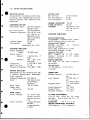
MS-808 SPECIFICATIONS
AMPLIFIER DESIGN
IC amplifiers including solid-state
switching and signalling circuitsCurrent-limited and short-circuit
protected.
*
MICROPHONE PRE-AMP:
Microphone Input:
0
200 ohm nominal
dynamic type
Mic Input Level:
-55 dB nominal
Frequency Response: 250-12k Hz with
mic limiter to
maintain level
and to prevent
overload
Limiter Range:
25 dB
t
SdB
Gain Adjust:
(gooseneck mic only)
HEADPHONE AMPLIFIER
Output Impedance
Range:
50-2000 ohms
Output Level-Speaker:
4 watts into 8
ohms
Headset:
+20
dBm into
600 ohms
<.25% THD @ 1kHz
Distortion:
Amplifier Gain:
35 dB
Frequency Response: 150-18kHz ±2dB
v
PROGRAM AMPLIFIER:
Switchable for 0-4 channels per CH4 Control Module with individual
level controls
Frequency Response: 150-18k Hz
50k ohms transInput:
former-less,
balanced
-20 to 0 dBm
Input Level:
Common Mode
Rejection:
>50 dB
P
POWER SUPPLY:
Output Voltage:
*
Output Current:
_
30 volts regulated; circuitbreaker protected
2 amps maximum,
MS-808
1 amp maximum,
IS-808
VOLTAGE GAIN:
Mic-to-line;
Mic Gain Adjust:
Line-to-output:
37 dB nominal
+5 dB
37 dB
a50 dB
>55 dB
adjustable from
>25 dB null to
fulL on
CHANNEL SEPARATION:
SIGNAL-TO-NOISE:
SIDETONE:
OPERATING CONDITIONS:
Channel Monitoring
Programmable channels with illuminated locking monitor switches
Sending Call Signal
Follows
position
of
"listen"
monitor switches
Call Light Sensitivity: 4 VDC
Signalling Voltage: 11 VDC
Capacity (MS-808)
Will
support up to 100 remote
headset
stations or 20
remote
speaker stations
System Impedance
200 ohms or 15k ohms bridging,
switchable
System Level
-15 dB nominal; 0 dB before
~~~~~~~~~~~~~clipping
CONNECTIONS:
Headset Inputs:
Stage Announce:
Speaker Mute:
(1) XLR male 4pin
(9) XLR male 3pin
(1) 30-pin male
(1) XLR female
3-pin
1/4" Jack
1/4" jack
External Speaker:
1/4" Jack
Line Outputs:
Program Input:
AC POWER REQUIREMENTS:
105-130 VAC; 48-62 Hz;
80 watts
maximum.
May be modified for 210
to 260 VAC.
DIMENSIONS:
19" x 3.5" x 9"
AMBIENT TEMPERATURE TOLERANCE:
0-50 degrees C. 32-12 degrees F
5
I.C
THE CLEAR-ICOM CONCEPT: TECHNICAL OVERVIEW
The DLC Series is a closed-circuit
intercom system that provides highly-intelligible two-way communicaA basic
tions in all environments.
system consists of:
--an MS-808 Main Station connected
to a number of Clear-Com Remote
Stations and/or various DLC System
Accessories, or
--an interconnected group of IS-808
Intercom Stations.
circuit shuts off the station's mic
preamp when the mic or headset is
disconnected, so an unused, on-line
mic does not add background noise.
Low impedance mic input lines (200
ohms) make the audio channels virtually immune to RF and dimmer
Each bridging circuit is
noiseterminated with a low impedance to
prevent crosstalk between station
pairs that have been simultaneously
selected for monitoring.
System Interconnection
All units in the DLC Series (MS/IS808, IF4-4, and PIC-4) interconnect
with a single cable which carries
up to seventeen audio "channels"
IFB, one
intercom, eight
(eight
point-to-point) plus DC power. Each
intercom station location may be
assigned to the point-to-point audio channel, which is referred to
as a "dedicated line."
Clear-Com prevents audio feedback
between the station's mic and speaker with individual anti-sidetone
circuits on each intercom channel.
Analog logic circuitry determines
the direction of the intercom sigregulating the gain circuitry
nal,
for the highest performance.
Most Remote Headset and/or Speaker
Stations connect to the MS-808 with
shielded
two-conductor
standard
One wire carmicrophone cable.
the other wire carries DC power,
and the
ries the audio channel,
shield acts as common ground.
needed
Only one termination is
throughout the system, and is accomplished at the MS- or IS-808.
Performance
The DLC Series is a distributed
each intercom
amplifier system;
station houses its own mic preamplifier with limiter, power ampli(for the headset or internal/
fier
and visual sigexternal speaker),
Electrical isonalling circuitry.
lation between the talk and listen
circuits is achieved, prior to the
switch matrix, by the individual
The mic limiter preamplifiers.
overload and maintains a
vents
transmit level from each
steady
station.
ThP "automatic headset
detection"
Power Supplies
IS-808 Stations are self-powered
and incorporate regulated DC power
supplies (I amp) for operation with
50-60 Hz line power.
115-120 VAC,
MS-808 Stations have regulated power supplies (2 amps) and the connectors to support up to 100 standard remote headset stations or 20
remote speaker stations distributed
Remote staalong a mile of wire.
tions bridge the intercom line at a
very high impedance and place a
Audio
minimum load on the line.
level always remains constant, even
when stations leave/join the line.
Both the MS-808 and the IS-808 are
short-circuit-protected, providing
an LED for "short" indication and a
circuit breaker re-set button.
The 28-30 VDC provided by the MSto
808 enables Remote Stations
operate with minimal current (headset stations, 10 milliamps; speaker
20 milliamps) while genstations,
listen levels (greater
loud
erating
than 110 dB SPL). The higher voltage and low current keep voltage
losses to an absolute minimum in
long lines.
6~~~~~~~~~~~~~~~~~
II.
0
INTERCOM SYSTEM SET-UP
A.
SYSTEM INTERCONNECTION
1) MS-808 & Standard Remote Stations
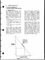
1.1 Station Capacity
The MS-808 has a regulated power
supply that delivers 30 volts at 2
amps. Therefore, it can support an
intercom system that contains any
combination of Clear-Com's 1-,
2-,
or 4-channel Remote Stations. The
number of Remote Stations that one
MS-808 can support depends upon 4
factors:
1) the current requirements of each
Remote Station
2) the length of the cable that
interconnects the Stations
3) the gauge of the interconnect
cable
4) the capacitance of the interconnect cable
Most intercom systems incorporate a
variety of headset and
speaker
stations. To determine the maximum
number that one MS-808 can support,
see the graph in Figure 2.
Match
the number of speaker stations in
your system to the number of headset stations.
If the intersection
falls within the graph's shaded
section, one MS-808 can support all
the stations in your system.
In systems where interconnect lines
between stations are longer than
1000 feet, we recommend you add a
second power source to act as a
back-up supply; this doubles the
system's capacity, allowing you to
include more Remote Stations. Main
Stations and Power Supplies can be
paralleled in the intercom system.
If your system includes two MS808's or one MS-808 plus another
power source (PS-452, MS-200, etc),
the system termination occurs in
only ONE of the power sources.
If your MS-808 is to support remote
headset stations only (MR-102A, RS100A, RS-201, etc), the system can
contain up to 100 units.
If your
MS-808 is going to support remote
speaker stations only (KB-llA, RM400, RM-120, etc), the system can
hold up to 20 units.
1OO
90
*
Example: If have
40 headset stations,
how many speaker
stations can my system
\support? Answert? 12 speaker
stations.
\
70
HEADSET
STATIONS
\
1,.X
60
30
40
~
~
.
.0
>
10~~~~~~~~~~~
40
20
0
1
2
3
4
78
56
9
10 11 12 13 14 is 18lW 18 19 2
SPEAKER STATIONS
ns
Figure 2fMaximum Amount of Remote Stations
1I.
Intercom System Set-Up, continued
1.2 INTERCONNECT CABLE
When
choosing interconnect
cable,
Each intercom channel is normally
fed
on standard
two-conductor,
shielded mic cableThis cable is
routed from a 3-pin male connector
on an MS-808 rear panel to a Remote
Station's input connector. One wire
in the cable carries DC power and
tile other wire carries the audio
signal; the shield serves as circuit ground.
keep in mind the following
derations:
consi-
The pin assignments on ALL 3-pin,
XLR intercom connectors (male and
female):
PIN 1-- COMMON
PIN 2-- +30 VDC
PIN 3-- INTERCOM AUDIO
2) The capacitance of the interconnect cable affects the frequency
response and sidetone stability
of the Remote Stations.
Total
capacitance should be .25 microfarads or less (capacitance between the conductor and shield;
equivalent to an intercom system
with 5000 feet of 50 pF/foot of
cable.
The MS-808 provides 28-30 VDC to
run the Remote Stations. Each one
uses minimal current (headset stations,
10
milliamps quiescent;
speaker stations, 20 mA quiescent)
and generates loud listen levels
(greater than 110 dB SPL).
The
higher voltage and low current keep
voltage losses to an absolute minimum in long lines.
If the voltage
drops because you've added many
extra Remote Stations or
great
lengths of cable, the stations in
the system continue to operate normally even with less than 12 volts
available.
CHOOSING CABLE
The MS-808 contains nine XLR, 3-pin
male connectors, one for each of
the eight channels and one for the
dedicated line.
Depending upon
what stations are in your system,
you will:
1) route each channel on a separate
two-conductor cable that goes to
single-channel Remote Stations,
or
2) route two channels together on
multi-pair cable to two-channel
Remote Stations, or
3) route Eour channels together on
multi-pair cable to the fourchannel Remote Stations.
8
1) DC resistance affects crosstalk.
In permanent installations, do
not use cable smaller than 20
gauge, stranded (except on runs
shorter than 100 feet).
Keep
the total resistance under 100
ohms.
3) Standard Clear-Com Remote Stations operate with cable that
has no more than 35 pF from
conductor to conductor, and no
more than 70 pF from conductor
to shield.
Cable for Portable Installations:
Typical cable for connecting the
MS-808 to portable single-channel
Remote Stations is rubber-jacketed,
two-conductor, shielded mic cable.
We suggest you try BELDEN 8413 or
the equivalent (24 gauge, stranded)
for connections of 500 feet or
less.
For connections that run
between 500 and 5000 feet, we suggest BELDEN 8412 or the equivalent
(20 gauge, stranded).
Cable for Permanent Installations:
We recommend you use vinyl-insulated
and jacketed
cable
for
interconnecting all permanently installed Remote Stations (wall-mount
or custom-mount units). This cable
costs less and is easier to pull
through conduit than the rubberinsulated type.
As
explained
before,
low-capaci-
0
0
TI. Intercom System Set-Up
continued
tance
We sug-
cable must be used.
have
gest BELDEN 8762 or the equivalent
(20 gauge, stranded) for up to 500
feet, or BELDEN 8760 or the equivalent (18 gauge, stranded) for up to
5000 feet.
low DC resistance--less
than
15 ohms per 1000 feet, with large
diameter conductors.
Cable should
have low interconductor
capacitance--less than or equal
to 55
pF/foot of cable, capacitance between conductor and shield.
If you don't use Belden cable, use
a similar type with the equivalent
wire gauge and capacitance.
Cable
(especially in longer runs) should
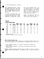
Consult the Belden wire specs in
Figure 3 to ensure that the substitute cable is the equivalent.
Figure 3
Belden Shielded Cables
Trade
#
Trade
# of
# of
Cond.
AWO
Inslaion
AWG & Thickness
(Stranding)
(inch)
Ja&et
Thickness
(Inch)
Nom.
O.D.
(Inch)
44
Shield
Coverage
Sugsed
Working
Voltage
Nom.
Cap.'
(p/ft.)
Nom.
cap...
(pI/ft.)
8413
2
24(45x40)
.019
.025
.190
100
300
30
55
8412
2
*a
20(26x34)
020
.043
268
84
600
30
55
8762
2
20 (7x28)
.014
.028
.196
100
350
27
49
W
8760
2
16(16x30)
.018
.028
.222
100
450
24
44
8725
8
20 (7x28)
.015
.030
.360
100
400
27
49
8723
4
22 (7x30)
.008
.019
.165
100
400
35
62
'Capacitance between conductors,
Capacitance between 1conductor and other conductor connected to shield.
Cable for Multi-Channel Lines:
When installing a system that contains two- or four-channel Remote Stations, you
can send each channel in its own two-conductor shielded mic cable, OR you can:
1) route 2
(Belden
2) route 4
(Belden
channels together in a two-pair, individually shielded cable
8723)
channels together in a four-pair, individually shielded cable
8725).
Whichever method you chose, make sure that the cable you select provides A
SEPARATE SHIELD FOR EACH CHANNEL.
See Figures 4 and 5, Two-Pair and Four-Pair
Cable.
0
9
Z 00 M~~~~~~~~
w
zC~~~~~~~
110<ic ><mw0
0
OX~~
c~~~~~
a
_
_
_
_
_
-4-to
0
om~z
zm-l
~
-r
mco
m0
~
zr
-to
zr
z
C
S~~~~~m
r
-u
_
~~~
0
S
Z~~m
~~rn
0~~~~
0~~~Dz
z
10~~~~~~~~~~~~~~
--lo
z~~~P1
m-m
0
*
0m rm0
II. Intercom System Set-Up, continued
1.3
INTERCONNECTION PROCEDURES
1) When routing cable from the MS-808 to the Remote Stations, allow at
least three inches behind rack-mount units for cables to extend from the
rear panels. Avoid sharp bends in the cabling.
2) Always route cables away from heavy AC power sources,
panels or electric motors.
such as lighting
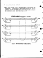
3) Portable and rack-mount Remote Stations have female/male pairs of input/output XLR connectors; when installing a system with these units,
it's easy to "daisy-chain" several stations along one interconnect path.
I STATION |1Ho
DAISY CHAIN
**
Alternately you might try Clear-Com's Quadropuss Splitter to feed lines
to individual Stations (the Quadropuss is a line splitter with one input
and three outputs, and is plugged directly into the MS-808 or installed
along the line). Both these methods lessen the amount of cable you need,
and also simplify installation.
4) Use of Conduit:
Wall-mounted and custom-mounted Remote Stations connect
to
the intercom system via 5-pin terminal strips instead of XLR connectors.
If you're using these in an installation site that has conduit,
run interconnect cables through the conduit. If the conduit has existing
wire, you can use that whether it's shielded or not.
Be sure
codes.
to install cable in accordance with
approved
local
building
5) Not Using Conduit?:
In installations where conduit is NOT used, and
equipment doesn't share a common ground, it is good engineering practice
to run an additional ground wire to tie all chasses together. This
decreases susceptibility to electrical noise fields.
6) IMPORTANT:
"Chassis ground" and "signal ground" (Pin 1 on intercom XLR
connectors) are NOT the same point.
DO NOT connect the chassis and Pin
I together.
The chassis is insulated from the signal ground with a
capacitor (.01 microfarad, 1.4 kV). This eliminates the hum and potential shock hazards that might arise should the Stations be at different
ground potentials.
Refer to the Permanent Installation Wiring Diagram (Fig.
connections.
O
7) Crosstalk:
amount
4) when making
When routing two or more channels to one Remote Station, the
of crosstalk is proportional to the amount of DC
resistance
in
the ground return.
Two ohms of resistance or less is ideal; two ohms
will give 40 dB of isolation.
Anything greater than two ohms will
increase crosstalk. Be sure to route each channel in its own shield.
II. Intercom System Set-Up. continued
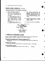
8) When using four-pair cable, you should connect all the shields and
This effectively lowers ground resistance and improves
ground wires.
crosstalk. See the Interconnect Cable Detail diagram, Fig. 5. Also, tie
any unused wires in the interconnect cable to Ground (Pin 1 on intercom
XLR connectors), thereby further improving crosstalk.
4-PAIR CABLE Belden 8725 or equivalent
A3F
'
'
I
A3F
A3M
/2
1
A3M
,"
,-2$
/|
A3F
A3F
,/,
Figure5
-INTERCONNECT
A3M
A3M
CABLE DETAIL
II. Intercom System Set-Up, continued
2) DLC SYSTEM INTERCONNECTION
DLC Stations and the PIC-4 Program
Controller connect to each other
with 12-pair shielded cable.
The
cable is input to the 30-pin male
connector on the Station's rear
panel.
With each DLC Station, we
supply two 30-pin female connectors
(these are attached to each end of
the interconnect cable).
*
*
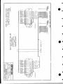
The following pages contain illustrations to help you construct the
interconnect cable.
We recommend
you use Belden 9768 or the equivalent
(twelve-pair,
individuallyshielded,
22 gauge).
*
a
g
Cable. especially in longer runs,
should have low DC resistance-1000 feet,
less than 15 ohms per
with
large
diameter
The IS-808 Station provides two 30pin connectors, one for "input" and
one for "output," so you can daisychain the unit with other IS Stations.
See the Daisy-Chain diagram
in the previous section.
The PIC-4 Program Controller contains one 30-pin connector for DLC
intercom/IFB input.
Since each MS-808 and IS-808 contains its own power supply, there
is no limit to the amount of mainframes that can be interconnected
within a system. (systems with IFB
must contain at least one MS-808
to provide power for the Program
Controller
and Talent Receivers;
see Section IV.)
conductors.
Cable should have low inter-conductor
capacitance-- less than
or
equal to 55 pF/foot of cable, capacitance
between
conductor
and
shield.
*
The MS-808 provides one
30-pin
connector for output to DLC Series
components.
Always route the interconnect cable
away from heavy AC power sources,
such as lighting panels or electric
motors.
Avoid sharp bends in the cabling.
Allow at least 3 inches behind each
DLC Station for cable to extend
from the rear panel.
0
13
Z
0
C
21
cLn
<
Q)
;0
<
F AK3PD-|iW
NW
Tl
<
E
-ER
C
3 I t(LFA
L P -ARa>>S222°D
(1l11
On
0
z~~~~~~~~~,
ELAC
E
r
F
WO
C OLO
O
LAEK
'FD -K
<
E3R~
L WN
_~~~~~~~~~~~~~~~~~~~I
_
IG
~[fTLEA
-- z
¢
L
...
IMS
R
0L
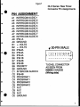
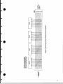
Figure7
DLC Series: Rear Panel
Connector Pin Assignments
PIN ASSIGNMENT
*
Al
A2
A3
A4
A5
A6
A7
A8
A9
AO
Bi
B2
B3
INTERCOM
INTERCOM
INTERCOM
INTERCOM
INTERCOM
INTERCOM
INTERCOM
INTERCOM
IFB-1A
GROUND
+ VOLTS
+ VOLTS
IFB-2A
~B4
IF6-3A/2
b
AUDIO
AUDIO
AUDIO
AUDIO
AUDIO
AUDIO
AUDIO
AUDIO
1
2
3
4
5
6
7
8
B4 IFB-3A
B5
B6
B7
B8
B9
IFB-4A
IFB-1B
IFB-2B
IFB-3B
PRIORITY
BO
C2
C3
C4
C5
C6
C7
C8
C9
GROUNDM AUDIO 9
IFB-4B
PROGRAM 1
PROGRAM 1
PROGRAM 2
PROGRAM 2
N/C
N/C
N/C
f 30-PIN MALE
o,
3 4 5 6 7 8 9
~~~2
- -_
__
0
-B
-
TUCHEL CONNECTOR
AS SEEN FROM
INSIDE CHASSIS
(Wiring side)
CO GROUND
15
II. Intercom System Set-Up, continued
B. ASSIGNING CHANNEL I.D.'s
The
MS/IS
Station with
two
CH-4
Matrix disables one
of
the circuits within the unit, disentirely from the
connecting it
should be used as a
It
system.
line
place to "park" the dedicated
slideswitch in systems that do not
use point-to-point communications-
The dedicated line has no external
it remains permacontrols for it;
nently "on," allowing the DLC Station operator to main tain constant
point-to-point communications with
another Station operator-
we set up the MaAt the factory,
lines in the
intercom
the
so
trix
assigned to
are
30-pin connector
the channels in a straight-forward
manner:
Intercom line I = Channel A
Intercom line 2 = Channel B
Intercom line 3 = Channel C
Intercom line 4 = Channel D
Intercom line 5 - Channel E
Intercom line 6 = Channel F
Intercom line 7 = Channel G
Intercom line 8 = Channel H
Intercom line 9 = Dedicated Line
When you interconnect DLC Stations,
the lines in the cable are not
to the specific
hard-wire-assigned
H) which are
through
(A
"channels"
controlled via the front panel.
Assigning each set of channel controTs on the CH-4 module to the
the
audio lines in the cable (and
Stations connected to the lines) is
done via the Station's Assignment
Matrix.
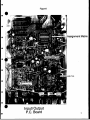
The Matrix is located on the Input/
Output Circuit Board inside the DLC
the top cover of
Station. Remove
the Station, and you'll see the
See
labelled Assignment Matrix.
Figure 8, Input/Output Board, for
exact location.
the horOn the Assignment Matrix,
corre1-9
labelled
izontal rows
spond with the nine intercom lines
run through the 30-pin connector on
the Station's rear panel (MS or IS
mainframe). Refer to the pin-out
chart, Figure 7, to see which pins
to
on the connector correspond
which intercom linesThe vertical columns on the Matrix
are labelled with alphabet letters
A-H and "D0/.." They correspond with
the
monitored via
the channels
CH-4 Modules.
The
16
Assignment
Control Modules provides two-way
communicating abilities on eight
intercom channels and a dedicated
The Modules let you pre-set
line.
the channel functions and control
channel monitoring.
position marked "off"
on
the
If you have an MS-808 that connects
to standard remote headset/speaker
System
stations instead of DLC
components, there's no need for you
to re-set the Assignment Matrix.
The 3-pin, XLR connectors on the
Station's rear panel directly correspond with the intercom lines; in
the line run through
other words,
XLR connector #1 is monitored via
the Channel A buttons, the line to
XLR connector #2 is monitored via
the line to
the Channel B buttons,
XLR connector #3 is monitored via
and so on.
the Channel C buttons,
XLR connector #9 is for the dedicated line.
To change the channel/line assignuse the point of a pencil
ments:
to
(or end of a paper clip, etc.)
or
up
push each Matrix slide-switch
thereby assigning
down its column,
a channel ID to each intercom line
run through the 30-pin connector
(it is possible to assign more than
one line to the same channel; you
can assign two sets of talk/listen
controls to one XLR input).
0
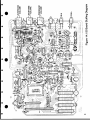
Figure8
i
i
i
~~~<
Matrix
' .Assignment
..
PormMsErGi
GoosneckMic Trim
19 N9
~Sidtn
Null
Input/Output
P.C. Board
17
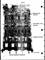
Figure 9
00
~~~~~~~~~~~SERIALNOSCC33t11
'I
Sidetone Null
Termination. Talk
a
:
A B
>
>
E
g
~~~~~Controls
Program Controls
5.-t
&
a
0
-
CH-4 Control Module
18
0
(front panel)
a
II. Intercom System Set-Up, continued
*_ C.TERMINATION
After completion of cable routing
you
and system interconnection,
must make sure that the system is
properly terminated once at a point
in the system.
Only one termination per channel is
All channels should be
neededterminated at any one of the MS or
IS Stations or other Main Stations
in the system, or at the MS-808 if
it's the only power source-
*
*
*
*
a
W
Termination for each intercom channel is accomplished with a dipswitch which is located on the CH-4
Control Module's printed circuit
Loosen the screws that hold
board.
the DLC
the Control Module onto
gently
and
Station's front panel,
the slot
pull the Module out of
until you have access to the dip
of 4,
(grouped in sets
switches
there is one set for each channel).
See Figure 9, CH-4 Circuit Board,
for exact location of dip switches.
The circuit board is labelled on
its far left side (next to the
first set of dip switches) with the
0.
*
Make sure a termination switch is
ofon" for all intercom channels in
Even if a channel is
your system.
not in use, you should terminate
it.
At all other DLC Stations in the
(also at all Main Stations,
system
Switchboard Stations, or Power Supplies, if part of the system), the
termination switches should be OFF
("open" position).
important to remember that
is
It
each channel, whether in use or
not, should be terminated ONCE at
intercom
some point within the
that point need not
system (note:
be the same for each channel).
In DLC Systems using IFB-4 Control
the IFB channels are terModules,
minated by the PIC-4 Program Controller.
PROGRAM SEND/RECEIVE
The rear panel of each MS/IS mainframe contains a 3-pin female XLR
connector for a balanced, auxiliary
The Station operaprogram input.
tor hears the program in the headset and/or speaker.
tial amplifier to accept a balanced
signal without using a transformer.
A -25 dB signal will drive the line
The input impeto full output.
dance of the program amplifier is
approximately 50k ohms-
headset
the
cases,
most
In
connector on the DLC mainframe's
front panel has the intercom and
program signals combined onto one
pin (pin 4), although the DLC mainframe is optionally available with
a 6-pin headset connector that has
The speaker output always combines
the intercom and program signals,
although the relative levels of
the
upon
dependent
are
each
settings of both volume controls on
the front panel (Intercom Volume,
Program Volume).
*
*
switch functions. Dip switch #4 in
set is for that channel's
each
termination
Each
termination"on" or
the
to
set
must be
switch
"closed" (not "open") position.
O
separate
program and intercom pins
for use with binaural headsetsThe
program input uses a differen-
The program level heard in the
the
headset is affected only by
However,
Program Volume control19
II. Intercom System Set-Up, continued
PROGRAM SEND/RECEIVE, continued
the program level heard in the
speaker is affected by the setting
of the Intercom Volume control.
If you're using a binaural headset
the Interwith the DLC mainframe,
com Volume has no effect whatsoever
upon the program level, whether in
the speaker or the headset.
The
DLC mainframe operator can
combine the the program with the
intercom on any or all of the chanIf he decides to do so, the
nelsprogram and intercom signals are
mixed at the Station and the ensuing signal is sent to the Remote
Stations on the desired channel(s).
To send the program on any channel,
CH-4
slide out the appropriate
The control to
Control Module.
adjust is a light-blue trimpot,
located close to the front panel
(see Fig. 9, for exact location of
all controls on CH-4 Module). Turn
and
the trimpot fully clockwise,
the associated channel will receive
the program signal at maximum leTurn the trimpot fully counvel.
and the associated
ter-clockwise,
channel will not hear the program.
Program can not
dedicated line.
be sent
on
the
Note: the Program Input XLR connector is wired in parallel with the
"program 1" lines in the mainframe's 30-pin connector (see Fig.
7 for specific pins).
E. CHANNEL SIDETONE NULL
Sidetone control enables the Station operator to vary the level of
his/her voice as heard in. his headset or speaker.
The CH-4 Module provides a sidetone
null trimpot for each channel. This
the
light-blue trimpot looks like
is located
Program trimpot, but
towards the rear end of the Control
Module circuit board (see
8 for exact location).
Figure
These trimpots adjust the sidetone
level for the individual channels.
Turn a sidetone null trimpot clockwise to decrease the sidetone heard
At the
on its associated channel.
factory, we set all these trimpots
for maximum null.
F. HEADSETS, SPEAKERS, & GOOSENECK MIC
An electret mic on a gooseneck
extension is permanently attached
to the front panel of the DLC StaThe length of the extension
tion.
is adjustable; loosen the screws
that hold the base to the front
panel, and you can slide the gooseThe gooseneck mic
neck tn or out.
is controlled by a Mic On/Off toggle switch next to the gooseneck
hase.
200
Beneath the gooseneck mic is a
for use with a
headset connector,
The headset condynamic headset.
nector's pin assignments are:
Pin I - Mic Common
Pin 2 - Mic Hot
Pin 3 - Headphone Common
Pin 4 - Headphone Hot
Do not use the mic or headset withtransin two feet of an AC power
0
II. Intercom System Set-Up, continued
UIADSETS, SPnAn
former,
hum.
a
& GOOSENECK KIC, continued
or the mic(s) will pick up
sponse.
See Figure 11, Headset
Extension Cord Construction.
The Station's headset/speaker amplifier can drive a headset to levels greater than 110 dB SPL.
When
the headset jack is not used, the
Station's amplifier gain is reduced
from 50 dB to unity gain, eliminating pick-up from the unused input.
All dynamic headset connectors in
Clear-Com Stations are 4-pin XLR
male connectors. These are for use
with monaural headsets, but can be
adapted for use with stereo (binau0ral) headets (see Section G).
If you want to connect an external
speaker to the MS/IS mainframe, use
one with impedance of 8 ohms or
more. Connect the two wires from
the speaker to the tip and sleeve
of a 1/4" phone plug, then plug it
into the external speaker jack on
the Station's rear panel.
The
external speaker always remains on,
and does not affect operation or
performance of the Station's builtin speaker (which is included when
the MS/IS mainframe contains an SP4 Speaker Module).
To assure proper level and performance, the headsets (or handsets or
mica) should have the following
The mainframe is easily adapted for
use with a stereo (binaural) headset. You will need:
characteristics:
characteristics:
Microphone Type:
Impedance:
Output Level:
Headphone Type:
output Impedance:
dynamic
150-250 ohms
-55 dB
dynamic
300-2000 ohms
Clear-Com can supply you with the
Model YC-l00 "Y" Cable, which allows you to plug two headsets into
the one 4-pin connector on the
Station's front panel.
Alternately, you can construct your own Ycable; we recommend you use Belden
8416 or the equivalent (2-conductor, 25 gauge) or Belden 8734 or
the equivalent (3-conductor,
22
gauge).
See Figure 10, Y-Cable
Cbnstruction.
*
You can also build an extension
cord for the headset, using the
same cable specified for the Ycable.
Limit the extension length
to 15 feet or less; greater lengths
lead to possible capacity coupling
between the mic signal and the
headset signal, which causes oscillation or a loss in frequency re-
-6-pin insert (male, Switchcrafttype) for the connector
-one jumper
-one capacitor, 100 pF 1kV
-small-blade screwdriver
--small needle-nose pliers
--solder iron and wick
To switch from mono to binaural:
1)
remove top cover from mainframe
2)
remove set screw from top of
headset connector shell (inside
front panel)
3)
remove 4-pin insert from connector shell by gently pulling
its wires towards rear of mainframe
4)
carefully unsolder all 4 wires
from the insert
5)
prepare the 6-pin insert by
soldering the 100 pF capacitor
between the insert's ground tab
and Pin I (see diagram next page)
(continued)
21
II. Intercom System Set-Up, continued
HEADSETS, SPEAKER & GOOSENECKC
IC, continued
(adapting mainframe to stereo headset connector)
6)
solder the headset connection
wires to the 6-pin insert:
a-- black & blue twisted-wire
pair to Pin I (black) and Pin
2 (blue);
b- other black wire to Pin 3;
c-- spare white/yellow wire to
Pin 4 (spare wire is tucked
inside the mainframe, in the
same
bundle as the
other
wires);
d-- orange wire to Pin 5;
e--jumper between Pins 3 and 6.
ORN~~~~~o
8~~~~~LK
WHH
7)
use pliers to move jumper JP2
from the MIX position to the
SEPARATE position (located on
I/0 PC Board between the Sidetone and Intercom Volume controls)
8)
Slide' the 6-pin insert through
headset connector shell; secure
with set screw
9)
replace top cover of mainframe.
10pF, I KV CAP
T/LU
0
HEADSET CONNECTOR
6-PIN INSERT:
WIRING SIDE
C. TRnnos ON I/O (INPUT/OUnPUy)
PC BOARn
There are three trimponts on the 1/0 Board that are set at the factory for
optimum operation (refer to Figure 14 for their location).
Dedicated Line Sidetone Null (reference designator, P4):
Adjusts the sidetone null on the dedicated line; should not require readjustment.
Gooseneck Mic Trim (P5):
Sets the level for the gooseneck mic sensitivity over a 10 dB range.
Master Program Gain (P6):
Adjusts the program gain from full off to full on,
>60 dB.
22
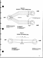
Figure 10
HEADSET "Y"CABLE CONNECTIONS
A4M
S~~~~~~~~~~~~~~~~~~~~~~~~~~~~~~~~~~~~~~~
A4F
O
~~~~~~~~~~~~~~~~PAIR
/
A<
t
BELDEN 8416
Note: Headset leads do not have
to be shielded on Belden 8734
CAUTION: DO NOT CONNECT
MIC GROUND & HEADPHONE
GROUND TOGETHER AT
ANY POINT
PIN 1: MIC GROUND
PIN 2: MIC HOT
PIN 3: HEADPHONE GROUND
Pin 4: HEADPHONE HOT
PAIR
PAIR
Figure 11
HEADSET EXTENSION CORD
15
OR
A4F
LESS
4g
SHIELDED PAIR
PIN 2: MIC HOT
PIN 3: HEADPHONE GROUND
Pin 4: HEADPHONE HOT
A
CAUTION: DO NOT CONNECT
MIC GROUND & HEADPHONE
GROUND TOGETHER.
23
III. MS-808/IS-808 OPERATING CONTROLS
The mainframe and CH-4 Module controlM are described as they
appear from left to right, viewing the front panel of the MS/IS-808.
...
-
~
~
~
~
~
-g
POWER SWITCH
PUSH-TO-RESET CIRCUIT BREAKER
CALL SHORT IND ICATOR
LED
The MS/IS mainframe has a power cord that connects to a source of
105-125 VAC, 50-60 Hz. When the power switch is turned on, it
illuminates, indicating the Station is ready to run.
The MS/IS mainframe provides a red LED that illuminates when the
Station's circuit breaker pops, indicating a short circuit or
phase reversal in the cabling. If the LED lights up, inspect the
interconnect cable, remove the short circuit, and press the
Circuit Breaker re-set to re-establish the system.
SPEAKER ON/OFF
This toggle
switch controls the MS/IS mainframe's built-in speaker.
CALPressing Call activates the Visual Signal Circuitry in the system,
allowing the Station operator to attract the attention of other
operators.
The Call button will signal the operators on channels that the
calling Station operator has chosen with CH-4 locking "Listen"
buttons. If the Listen buttons for Channels D and E are on, pressing Call will signal only those Stations on Channels fland E.
If all Listen buttons are enabled, all connected Stations will
receive the Call signal.
When a Remote Station sends a Call signal, the MS/IS Station's
Listen button for that Remote Station's channel will illuminate
brightly (whether it's on or off).
24
-
III.
MS/IS-808 Operating Controls, continued
S/A-- STAGE ANNOUNCE
"Stage Announce" allows the MS/IS Station operator to add his
words spoken into the mic to the intercom system to an external
output. When the operator presses the S/A button, the mic preamp
output is added to the rear panel Stage Announce connector (1/4"
phone jack) as a balanced, line-level signal, with 600 ohms impedance. The S/A function has no sidetone.
The MS/IS mainframe rear panel also provides a 1/4" phone jack for
"Speaker Mute." Speaker Mute provides a contact closure when the
Stage Announce function is activated, allowing you to use a relay
that will shut off or mute an external speaker located close to
the MS/IS Station (so there's no feedback). The Speaker Mute phone
jack should not be used to send a signal to a speaker.
UNLABELLED BUTTON
On the front panel of the MS/IS mainframe, there is an unlabelled
button. Depending upon the specified configuration when your
system was ordered, this button is any of the following:
0
a) unwired
b) "All Page" (talk to all channels at once)
c) "All IFB" (dip program and cue all talent at once)
You might choose to wire up this button yourself; if so, call our
Sales or Engineering Department (415-861-6666) for assistance.
PROGRAM VOLUME
This front panel knob adjusts the overall volume level of the
auxiliary Program signal in the Station's speaker or headset.
SIDETONE VOLUME
This knob controls the overall volume level of the operator's
voice as he hears it in the Station headset/speaker. Sidetone
control also prevents feedback when the Station is used with an
external speaker.
The sidetone control does not affect the level
of the operator's voice heard by other Stations or the level of
incoming signals.
As you turn the knob clockwise
overall sidetone level increases.
Sidetone can be varied from fully off to fully on, "no null"
level. For maximum speaker output without feedback, turn the
sidetone knob fully counter-clockwise (maximum null).
INTERCOM VOLUME
This knob adjust the overall volume of the channels monitored in
the speaker/headset of the DLC Station.
25
III.
MS/IS-808 Operating Controls, continued
CH-4 Control Module: TALK/LISTEN MONITOR CONTROLS
The front panel of the Control Module contains four pairs of intercom channel controls.
For each channel, there is a "Listen"
push-button and a "Talk" toggle switch.
When a square "Listen" button is activated, it dimly illuminates,
locks into place, and allows the operator to listen to activity on
the associated channel. The operator can listen to as many channels as needed.
NOTE: the positions of the Listen buttons determine which channels
will receive a visual signal when the MS/IS operator presses Call;
the Call signal travels only on channels whose Listen buttons are
ON.
The "Talk" toggle switch has three positions: on, off, and momentary on. The Station operator can talk on as many channels at the
same time as s/he wants.
Activating the "momentary Talk" function automatically dips the
Station's speaker output approximately 6 dB so you don't get feedback.
ISO OPTION
The CH-4 Module contains a certain jumper within the electronics for each channel. When removed, the channel becomes
an ISO line. To access an ISO channel, set that channel's
"talk" toggle switch to the momentary on position. This
lets you talk to the Stations on the ISO line only, and
disables your "talk" and "listen" ability on all other
channels, regardless of their "talk" and "listen" switch
positions. You can still hear the external program (if
input to the auxiliary input) while communicating with an
ISOlated channel.
Please call the factory at the above number if you'd like
to modify any of your channels for ISO operation.
26
4
E
1921
-
~ ~~~~~~~~~~~~~
_0
---
-I---_
_
*~~
-
Cs
0)
c {~~~~~~~L
M
-
---
_-----
_
0~~~
- -
ooE~~
*
I
C
- -
U
-
-
4
E~~~~~~~~~~~~~~~~~~~~~~~o
0
-~~~~~~~~~2
wJx
z-
u
L
z
0
M
C^)2~~05
1U
GU o
~
<
>
>
Z >h
wri~
0oD
8
~
e a. n l
C/
~
2 4tt wuwt@ i.+X.................... g4@== . fi iw~fimu.S....................... = .
/fiX@
t
b
hwwg n-a
#g
i
g
t
t yt
t
x
j''.'W
R6
1
ww
:5,.Xfi
ff
iw
X
a
g'
u t
i
2~~~~'
i
&2
.00)
2 U7Z rmt
'l
8~~~~~~~~~~4ttI
d
n?
a~u~ ,__
g4~
?
_~
o
~~
2 88
2?E|8§
2
-|2
Q(;L
t
.
QI
II}H? "e,
9E:Et i |
gfi-mN
~~
??
J
.
2i?
IW°
<NC
~~~~~~~~~~
,d'7
G
......
t%
8
r?88 lg 6.
/~~~~~~
N
IN
S
i.??'
?
S
ww
aw
2/d,,d jE
it
w'D
t
xd
Std0,
;
/9"l2,
,
<td
oZD
i g
icm?
i
ii
22i0iB>B2a
d
We -/
.
?
1
2 ^
* '~~~sD
9
2
3
2
2
2-2,
?gs
?
/D
d
e'D ?2t21/
'0
?
|w
~~~~~d ~~g3W
Egi
}2?3W2z2
S 2 '22,w
g22
2
gsk;it
?|D218
r
'*?
2,
0 |&2
*w,,*la n
3NNVHO
Dw Ggr
,?,<B|N'g<
E
g
,DrgD
s'gj
D. //r
w
?
w wwwwwwww ww
~
w
~tD2
r
X
?ww O >Stu/Sw
<5tZII~~~~~g
w.
'+63
?.
.S?'
133
S82H
J ?.
,g=,.8
I
?
. t~~~~~~~~~~~_7,
i
w >2
//S H:a
4; ? ~
G~~l _ ffi
Gjn
St
j
,Ei
g
'
@
fmGiaftim
R
U0
Ot}
>~~~~~~~~-etn
i
4
Il.0 4I
mSa
T N~w }
t},°o
eE
f~
vw.l
X
v@,
:
: 0
rk2
g'X
9~~~~~~~
> >>
g
_g~~~~~f
,
X
d yS +gy+e+'>0~~~~~~~w
Jg
0X~
0
g
]~~~~~~~~~~~~~~~~~~~
t 3]0
3
t<
l0l
_~~~~~~~~~~~~~~~~~~
X__<:, J ,0
cc
20~~~~~~~~~~3
IMP
r
w I
C3
LJ
OH
u
0
j
0 N
u
Qz
IC3
If
C
XL
Li In
1
0Ln
j:I
(L Z
M
0
"I
.1-0
P. C)
C.)
CD
-3 N
z
0
Li
Li 0
Lnu
C3
EOL(l
V/s
U0
0
Z
0
L
a
0
0
C.)
to
003
w
>
Q Ng
CD
Ng
j li
10H
C+
rl
13
J
- - - - - - - - - - - - - - - - - - - - - - - - 0 9 0
0 0 0
I FU 00 0
00
cc u * 00a**
0
co * 0000q
**qe
*f00
< o o0000
0
n
00
j
w
z
2
4
I
u-
90
l7Lo
MSLl (2
zZ
In <
00
Z
N 0
z0
IC 2
jY j
wx>
z
0
7
0
Li
u
> 1,9
ko,
C]
33
9 0 0 0 0
0 0 0 * 0 J
00
0 0 J
u 0 0
cl * 0
C3
4C2-,n0
x ZLI C3d
w 0xmm
2
Ln
co
C
Q
Q
C
U a
7 z Li
CL Li
-CO3
<
co
Ir
co
Ln
6-
C-
LJ
0
CC
EC
zDL co
CL
co
I
'u
Ul
I
.j
z
z
j
D 0
<
rile
0
14
LO
A
0
- - - - - - - - - - - - - - - - - - -u- - - - - - - - - - w0T
13
LI
Z
EO
z wL,
-co
0
z
w
71
0
000
wUZU
0
a<
<
z Z
>n o
- I>>
>
>
'N
0co
Li
=3
Po<L
41 I, Si
CZ,co q, 'D
v - w tq
j 2
co co co to co ID co to
L
I U19
>
- - - - - - - <
.j en
ci I > > jj Q 7 m
Z Z 0 0
m C
q
I
1IT COI Q
- - -
7
Z
M
0)
LL
q
C
11 jI
00,
a0q
r
NNN
NWj-
- - - - -
---------N
a
N 0 C
a
j
C] 0 co
10 0
co
co
k,
co
19 l
to
mco 0
0 M33
19 0 n n N
0 0, 'D
0m
0 0
N-
0
- -
a C
-
m
(C
HN-:H
L( t L
0
N
z
ED
co
6 da
n N
C
- -
T
-
n
-
Im
- -
L7
C
co
Nj
q
N
H-
- - - -j47nN00
- - - -
T
Li
c2j)
7
N -
1,
-J
I
cc
7
LIJ
C:]0
0
co
L- - - - - - - - - - - - - - - - - - - - - - - -
u
N -
61Q
0LLI
u
0 TC
00
111
LJ
NI
T
a
Q 0
q
I
L-
cq W
44'
4W
- - - - - - - - - - - - - - - - - - - - - - -
vI
q
V n N
N
0
Im
NJN
00
0
TP
0
j
w
z
z
3
co
GI
Z
Fu
C3 C]w
m
cc
z
O
L-
5;
- - - - - - - - - - - - - - - - - - - - - - -
L-
C]
Cj
- - - - - - - - - - - - - - - - - - - -
4 4,
W
4
10
>
11
z
4
a
w
cc
IA AOq:
QNLJ
jz
M3
K
co
u
Ld L
GK
Fz<J u j
GI
0
F- 0 K
G.
>
C
In
- -
0
U-~~~~~~~~~~~~~
SF2
22
~
WI
~
.
2
t~I2
ij
~ ~
^~~~~~~~~~~~~~~~~~~~~~~~
W
2U~
0~~~~~~~~~~~~~~~~~0:0~~~~~~~~~~~~~~~~~2
~~~~~2d
0C
10
I
*
-I
I~~~~~~~~~~~~~~~~~u~
-
0
-
-J~~~~~L
-
- s-
-
-
--
~~~~~~~~~~~~~
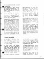
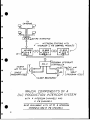
TV
CAMERAS
W4A 4zW/RE INTERFACE
*
IINTERCOM STATIONS WITH
t IFS CONTROL MODULES
,INTERCOM
*
.
-80
~~~M.
W/ CH4
W
PROGRAM INTERRUPT
P/C-4
iALENTr
with TR-50
A l
SINGLE
|CONTROLLER
TALENT
~~~~~~TR-62'1with
SPLIT
J_^((
(PROGRAM FEED)
SPROGRAM FEED)
TALENT RECEIVERS
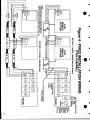
MAJOR COMPONENTS OF A
DLC PRODUCTION INTERCOM SYSTEM
WITH
4 INTERCOM CHANNELS AND
4 IFS CHANNELS
ALSO AVAILABLE WITH UP TO 8 INTERCOM
C CHANNELS AND 8 IFS CHANNELS
34
S
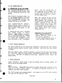
IV. DLC SYSTEM WITH IFB
A. INTRODUCTION TO THE IFH SYSTEM
The Clear-Com IFB System is a oneway program interrupt system that
is fully integrated within the DLC
System.
PIC-4.
The DLC System input is
only connected to the primary PIC4, which then connects to the secondary unit via a 25-pin D connector and ribbon cable.
This flexible IFB System sends one
of two program channels to talent,
and permits multiple intercom station operators to interrupt the
program and access the talent.
Split program feeds are possible,
which allow the talent to monitor a
program continuously in one ear and
have program interrupted in the
other ear.
When the director (a DLC Station
operator) presses a button on the
IFB-4 Module, the station's mic
activates and disconnects from the
"talk"
portion of the intercom
system to allow talent cueing. The
"listen" portion of the intercom is
not affected, which permits continuous monitoring of the intercom
during IFB use.
A system with one PIC-4 provides
four channel outputs to talent;
however, eight channels are possible by daisy-chaining two Program
Controllers (PIC-4) together.
One
is
called the "primary" PIC-4,
while the other is the "secondary"
Components of an IFB System:
--PIC-4 Program Controller
--Talent Receivers (TR-50 or TR62), up to 4 per PIC-4
--a DLC Intercom System with at
least one IFB-4 Control Module
1. PIC-4 Program Controller
The PIC-4 contains all the controls and connectors to provide the link between
the IFB/intercom stations and the talent receivers. Each PIC-4 has four outputs
to Talent.
With each Talent output, the PIC-4 provides a control for dip level and switches
for selecting which continuous and/or interruptable program feeds the Talent
will hear.
The PIC-4 is powered by Clear-Com, connected via the 12-pair DLC
System cable.
2. Talent Receivers
Talent Receivers allow talent to hear the program and cues coming through
PIC-4 from the intercom system.
the
TR-50
This miniature, lightweight belt-pack has volume control and a clip for attaching it to a belt or under a table.
It contains an earphone connector and is
supplied with Model TS-1 earpiece.
The TR-50 accepts one program channel,
two-conductor shielded mic cable.
and connects to the PIC-4 with standard
continued
35
IV. DLC System with IFB
2. Talent Receivers, continued
TR-62
The TR-62 is a compact two-channel belt-pack that allows the talent to monitor
uninterrupted program in one ear and interrupted program in the other ear.
Ideal for sportscasting, the TR-62 provides a separate volume control for each
program. It works with any binaural headset, 150 ohms or greater.
The TR-62 connects to the PIC-4 with individually-shielded two-pair cable.
3. DLC System With IFB
IFB-4 Control Module
This 4-channel module plugs into the DLC Station mainframe.
can be plugged in for accessing up to eight talent.
One or two Modules
The IFB-4 Module contains 4 momentary push-buttons, each of which is associated
with a separate IFB channel/Talent output.
The buttons glow continuously for
easy identification.
The DLC Station mainframe contains an ALL IFB pushbutton
accesses all talent.
that
simultaneously
B. IFB SYSTEM CONNECTIONS
The PIC-4 rear panel provides two
types of intercom input connectors:
3-pin, XLR-type female connectors
for
separate intercom
channels
(four), and the 30-pin male connector for the DLC System line.
The
PIC-4 is powered by Clear-Com.
1. Intercom System Input
Route 12-pair DLC interconnect cable from any MS/IS mainframe to the
PIC-4's 30-pin connector ("IFB Interconnect").
3. Talent Receiver Output
If a single program signal is fed
to Talent,
then the Receiver used
is a TR-50 with TS-1 earpiece,
and
the Talent Out connector on the
PIC-4 is a 3-pin XLR male.
Interconnect
cable is standard twoconductor shielded mic cable.
If a split program is fed to Talent
(both program inputs used),
then
the Receiver is a TR-62
with a
binaural headset, and the Talent
Out
2. ProgramInput
The PIC-4 has two 3-pin female XLR
connectors for balanced
program
inputs.
The program input uses a
differential amplifier to accept
two separate,
balanced signals,
without using a transformer.
A
signal
ranging from -18 dB to +16
dB will drive the line to full
output. The input impedance of the
program amplifier is approximately
50k ohms bridging.
36
connector on the PIC-4 is a 6-
pin XLR male.
Interconnect cable
is two-pair,
individually shielded
cable.
NOTE: On the DLC mainframe rear
panel,
the auxiliary program input
(3-pin XLR-type female) is wired to
the Program 1 pins in the 30-pin
male connector.
IV.
DLC System with IFB, continued
C. PIC-4 OPERATING CONTROLS
After you connect the PIC-4 between
the intercom system and the Talent
Receivers, and you adjust all levels and controls according
to
desired operation, then the PIC-4
becomes "transparent" and need not
be an "active" system component.
Program Select Toggle Switches
Each Talent Output (AB, C, and D)
is associated with three controls.
The secondary PIC-4:
--connects to the DLC System via
ribbon cable input to the 25-pin
D connector on the rear panel
(labelled "extender")
-- is
modified (by Clear-Com)
with
the addition of four jumpers
(at
JP1-JP4 on PCB) that permit
the
system extension.
The "Non-Int" switch allows you to
select which one program the TR-62
will receive continuously, while
the "Int" switch selects
which
interrupted
program (plus cues)
will be monitored by either the TR62, or the TR-50. The numbers "I"
To send program and cues to eight
talent people, two IFB-4 Control
Modules are required;
these modules, however, need not be in the
same DLC MS/IS mainframe.
One
Station operator (the director, for
instance) can have access to Talent
Program Level 1 & 2: Adjusts volume
level of associated program inputs
#1 and #2.
0
8-CHANNEL IFB SYSTEM
If your system includes two PIC-4
Controllers, one is considered a
"primary" unit and the other is
considered "secondary."
and "2" designate the program feeds
1-4
as input to the PIC-4 rear
(ie, Pgm #1 & Pgm #2).
another operator (such as the assistant director) has access to
Talent 5-8 with another IFB-4 Module.
panel
Dip Adjust: Allows you to vary the
dip amount from full on to full off.
via one
IFB-4
Module,
while
37
IV. DLC System with IFB, continued
0
D. IFB SYSTEM SPECIFICATIONS
Frequency Response:
Distortion:
Signal-to-Noise Ratio:
IFB Line Level:
100-15k Hz, +/-1 dB
<.1% THD @ lkHz
better than -55 dB
-10 dB
Pic-4
Program Inputs:
two, selectable to each talent
1 for interrupt, 1 for non-interrupt
Program Input Level:
-20 to +15 dBm, 50k ohms bridging, balanced
Program Output on IFB Line: -10 dBm
Program Dip Range:
0 to -40 dB
Power Required:
27 ma quiescent @ 28VDC supplied
by Clear-Com line
Dimensions:
19"W x 1. 75"H x 4.5"D
Connectors:
Program Input:
Intercom Input:
Talent Output:
DLC Input:
Extension:
(2) 3-pin XLR female
(4) 3-pin XLR female
(4 total) 3-pin XLR male (single program feeds)
or 6-pin XLR male (optional split-feed program feed)
(1) 30-pin connector
(1) 25-pin "D" connector for
extension to second PIC-4
IFB-4 MODULE
Controls:
IFB interconnect:
(4) momentary push-buttons (glowing)
20-pin ribbon cable
TR-50 TALENT RECEIVER
Earphone Type:
Earphone Impedance:
Max. Output Level:
Power Required:
Headset Connector:
IFB Connector:
dynamic
30 ohms or greater
+20 dBm
10 ma quiescent @ 28VDC supplied by Clear-Com line
1/8" miniature jack
3-pin XLR male
TR-62 TALENT RECEIVER
Headset Type:
Headset Impedance:
Max. Output Level:
Power Required:
Headset Connector:
IFB Connector:
dynamic
>150 ohms
+20 dBm
15 ma quiescent @28VDC supplied by Clear-Com line
6-pin XLR male
6-pin XLR male
Specifications are subject to change without notice
3B
4
4
0
V. WARRANTY & MAINTENANCE
Your Clear-Com System contains modular, solid-state equipment that
allows system expansion and field
serviceability. Efficient ventilation is inherent in chassis design.
Rugged packaging guards
against
abuse.
The intercom station chassis is constructed of .090 5052-H32
aluminum,
and it contains doublesided,
glass epoxy
plug-in PC
Boards. Our circuitry is conservatively engineered to assure the
longest component life.
We shield
heavily against hum, RF pick-up,
and solid-state dimmer noise.
Before shipping, we test each unit
to ensure that it
individually
meets or exceeds all specifications. All units are guaranteed by
Clear-Com against defects in materiaTs and workmanship for a period
of one year following date of purchase
(90 days for headsets-- see
the warranty card enclosed with the
unit).
Our Engineering and Service Departments will gladly give you technical advice and assistance.
If you
have any questions regarding operation, modifications, or applications of your intercom system, call
us between 9 a.m. and 5 p.m. at
(415) 861-6666 (Pacific Standard
Time).
0
.@
39
VI.
TROUBLESHOOTING
Symptom
Cause
Remedy
a. Plug unit into dependable AC source
b. Replace fuse; if it
b. Internal fuse is
blows repeatedly,
blown; could be
bridge rectifier
caused by power
or other component
supply failure.
probably shorted
inside power supply.
Have power supply
fixed.
___________________________________________________________________________0
a. Remove cables, one at
a. Shorted or mis-wired
Circuit breaker
a time, from Main
interconnect cable
trips repeatedly;
Station until faulty
short circuit LED
line is located. Check
remains lit
for shorts between
Pins I and 2.
b. Defective remote unit b. Check remote unit.
System is nonoperable; power
switch is not
illuminated
a. Loss of AC power
Hum or buzz in system
a. Inductive pick-up
caused by close
proximity of Main or
Remote Station to
a. Relocate offending
unit.
power lines or
transformers.
b. Due to ground loop,
caused by improper
grounding of system.
b. Reverse power cord,
lift ground (see
Installation Instructions.
c. Check resistance
c. 10 ohm chassis
between chassis and
ground resistor (R14)
Pin I of connector,
in power supply is
make sure it's ten
open*
If not,open
ohms.
power supply and
replace resistor.
d. Move mic away from
d. inductive pick-up
"hum field" or use
by headset mic; check
carbon or electret
by switching mic on
headset.
and off
_________________________________________________________________________6
a. Move closer to
a. distance from mic to
Excessive background
mic
lips is too far
noise pick-up by mic
b. Lower headset/
b. volume too high
speaker volume
c. Turn off all unused
c. too many mics "on"
mics
in entire system
…_________________________________________________________________________
(continued)
40
0
TROUBLESIOOTING
Cause
Symptom
Remedy
a. Check sidetone levels
b. Check termination
c. Volume too high at
one station
d. Two or more speaker
stations have mics
on simultaneously;
speak one at a time
(per channel)
0____________________________________________________________________________
System Feedback
Acoustical
* Power Supply's 10-ohm resistor is opened when the system
ground comes in contact with something "hot," with respect to the Main Station Earth Ground.
Should this
occur, we recommend you carefully check the system
ground and AC distribution in the area. NOTE: THIS IS A
POTENTIALLY DANGEROUS SITUATION; IF IT OCCURS, A SHOCK
HAZARD MAY OCCUR BETWEEN METAL BOON OF HEADSET AND
GROUND.
41
PILL OF MATERI ALS
6AsSEmb
150041
0
~~~~~~~
410017
410018
410020
410021
RES
RES
RES
PES
CF
CF
CF
CF
1/414
1/4W4
1/14W
1/4W4
52
5%
5%
5%
410022
410023
410024
410025
410026
410027
410028
PEG
RES
RES
RES
RES
RES
PES
CF
CF
CF
CF
CF
CF
CF
1/414
1/4W4
i/4W4
1/4W4
I/4W4
1/4W4
1/4W4
5%
5%
S%
52
5%
52
52
27K OHMS
561< OHMS
100OK OHMS
608< OHMS
150K< OHMS
1801< OHMS
2201< OHMS
6
1
2
1
1
2
10
RES CF
1/4W4
5%
4701< OHMS
3
3
2
1
6
I
2
2
1
3
2
I
2
I
3
1
1
3
1
I
1
1
I
1
1
1
1
1
2
3
16
410032
410033
410036
410038
410039
410040
410041
410044
410046
410049
410055
410056
410059
410063
410065
41006?
410071
410077
410082
410083
410084
~~~~~~~
410086
410095
410097
470033
470034
470040
480000
~
£67
C72
£73 £63
£0
C1?
C21
C64
C31
£36
£42
C4
£2? C14
Cs
C25
£26
C24
£12
£2 C?
£70
£49
£46
C69
£50
£9
£41
£30
£75
R(ES CF
410030
0
2
2
I
2
1
4
2
2
6
4
I
2
1
1
410016
~~~~~~~
0
10% SOO
C22
C74
£52
£61
£65
£55
£15
C29
£13
C59
£62
£23
£33
£36
£57
410010
410011
410013
~~~~~~~
0
DISC
~~~150043
CAN .471W MONOLYTHIC SOY
35V P.L,
480001
480008
400012
480018
480021
~~~~410007
1/4W4 52
15K OHMS
22K< OHMS
33K< OHMS
47K OHMS.
121< OHMS
~~~~~~410031
PES CF 1/4W4 5%
181< OHMS
[RES CF 1/4W4 5%
330K• OHMS
[RES CF 1/414 5%
6.81< OHMS
RES CF 1/414 S%
82
OHMS
RES CF 1/14W 5%
47 OHMS
RES CF 1/14W 5%
2.71< OHMS
RES CF 1/4W4 5Z
1,2K< OHMS
RES CF 1/14W 5%
RES CF 1/414 5% 680 OHMS
OHMS
560
RES CF 1/4U4 52
91K OHMS
RES CF 1/414 5%
1.5K< OHMS
RES CF 1/4W4 52
I MEGAOHM
RES CF 1/4W4 52
MEGAOHM
ID
[RES CF 1/4W4 5%
PES CF 1/8W14 I 6.81K OHMS
22 OHMS
1/2W4 52
PES CF
1.8 MEGAOHMS
RES CF 1/4W4 5%
100 OHMS
RES CF 2/4W4 5%
4.7 MEGAOHMS
RES CF 1/4W4 52
PEG CF 1/2W4 S% 470 OHMS
RES CF 1/4W 5% 24K< OHMS
[RES CF 1/4W4 52 431< OHMS
RES CF 1/81W 1% 2.67K OHMS
RES CF 1/814 1X 20.01< OHMS
RES CF 5% 1/4 WATT 1.2 MEGAOHM
RES CF 1/4W4 5% 2401< OHMS
REV 21< TRIMFOT BECKMAN4 #91AR21<
REY SON< TRIMPOT CTS/BECKMAN *9IAPSO1<
REV 100K< POT PC MTG CLAROSTAT ff0415
DID 1N4148 SIGNAL DIODE
~~~~410085
1N4001 RECTIFIER DIODE
MPS-A63 TRANSISTOR
LH384 IC POWER AMP 14-PIN DIP
LM741 IC OP AMP 8-FIN DIP
NE5534 OF AMP LOW NOISE
DI0 1lN957 7ENEP DIODE d.SY .4U4
ICS RC£4559108 DUAL OF AMP 8-PIN DIP
TNN 2N5639 N4CHANNEL JFET
AAA ICS NE5532 DUAL LO NOI E OP AMP
[CS [IG306A ANALOG SWITCH QUD
ICS CD40498 CMOS HEX INVERT BUFFER
TRA UPC7SLlSH NEC VOLT PEG. ISV 10OMA
TRA J174 P-CHANNEL JFET
914T I'PDT SNAP ACTION £11K 48221YAY2
SWT SPOT SNAP ACTION £SK#8I21YAV2
OWL1 1OXIO MIN4I MATRIX AMP#436270-1
DIG
[PA
YES
ICS
ICS
~~~~~~ ~~400026
480056
400069
480070
400073
400076
480078
480079
510041
510043
510046
10K OHMS
OFF ['CS IO
I
3
3
3
2
6
1
3
3
2
1
2
3
3
S
CAT 4.7 (IF TANTALUM
CAD 680FF DISC 10% SOY
CAC 2.2UF N.P. ELECTROLYTIC 5OV
CAE jGOur 20%MAX 25V MNI NP
CAM 1 RED CERAMIC MONO 15% SOY RADIAL
CAM .01 MONOLYTHIC lox 5OV
CAM .04? MONOLYTHIC 10% SOY
CAM ,22UF MOIJOLYTHIC 1O4ZU IOYV
CAE 47 UP 35Y ELECTROLYTIC CAP (SMALL)
CAM .022 UF MONO C1<05 10x SOY
CAD .002 UP DISC OP MONO CNOS 102 SOY
CAM .1UF MONO CK<05 10Y 10%
PCI' DLC I/O CIRCUIT BOARD
TER DIP 16 PIN DIP SOCKET2
50£ 8 PIN DIP SOCKET
TER 3M 26 PIN(0I'L ROW)3M*3491-1002
SOC SINGLE PIN SOCKET FOR DLC OPTION4 JUMPS
TER HEADER MULTI PIN HEADERIMIN IS PIN)
LBL DLC I/O BOARD MATRIX SWIT LABEL
3.9 OHMS
PES CF 1/4W4 5X
22 OHMS
5%
RES CF 1/4W
OHMS
220
52
RES CF 1/4W
11< OHMS
5%
1/4W4
CF
RES
2.2K OHMS
RES CF 1/414 52
4,7K< OHMS
RES CF 1/4W4 52
150044
150061
150065
150072
150073
150076
150070
150080
150081
150062
150084
ISOOGS
170075
210075
210101
210102
210109
210112
250216
410001
410004
0
OIT,
20FF DISC 10%
100FF DISC 10%.
20011' DISC 10%
IUF TANTALUM 35V A.L.
22UF ELECTROLYTIC 16V 0,L.
I00UF ELECTROLYTIC 35V'.),L.
15FF 1I5£ 102
470FF CERAMIC DISC l0% SOY
.005UF DISC 10%
2.21F TAN4TALUM 35V
220UF ELECTROLYTIC 35V R.L.
39PF ['1C5£ S
jour ELECTROLYTIC 16V ROL.
.221F MOJOLYTHIC 5OV
.IUF MOIJOLYTHIC 1042U 50V
CAD 47PF
AGEI
A
M~ODUILE'IV.6
('ESCRIFTI ION
CAl,
150001
CAlR
150006
CAD
150007
CAI
150009
CAP
ISO0lO
CAE
150011~~~~~~~lbol
CAl'
150013
CAI'
150014
CAD,
150016
CAI
150019
CAL
150021
CAD'
150026
£AE
150027
CAN
150034
CAM
15003b
.
S
ASY DIEC I/Cl
71014 4
PIN
4
20
59
1
4
1
4
2
B
V
3
4
I
8
I
1
I
I
I
1
3
I
2
1
I
1
1
1
2
1
J103
£3')
C:20
C2>
C66
C68
£45
C60
CA
C18
C34
£56
£10
£16
£3
£19
£44
£53
J106
C37
CIL
C43
£48
£32
£71
C54
C47
£40
£35
J105
C51
J104
R110
0111
012
R101
R47
R17
P39
RI
R93
R38
032
R(48 R46
R50 R49
R106
0112 RIO?
40
RB?7 RI?
096
R86
R103 0102
0104
R98
P11
P114
P68 R67
RDA P4
PS9
R30
PIS
A100 R59
76
P83
P84
[(65 P64
RIO7 R66
PS
P35
P69
R78
P34
0113
062
061
R23
R56
P70
074 072
R88
R91
094 R92
R99
081
016
R57
R58
R75
P2 RIO
R27
R25
R20
[(45 031
R21
053
P85
R22
[(3? R24
R73
P54
R29 R55
P5I
P52
R60
033
042
R97
R71
R28
RO0
R36
R10S
R90
R95
P14
P43
R82
P105
R77
09
07
R41
R79
P13
PS
F4
P6
P3
P2 El
(13 (12 Dl
04
05
D18
D12
SIT
(114 ['13
D15
D7 0.6
D9
D8
D17
02
[C8
IClo
1C2
O1d
ICS
1C4
1C3
01
ICI
ICIl
lCd
IC?
IC?
03
62
53
S1
S4
R44
R15
PS
063
R3
P26
[.10
43
BILL OF MATERIALS
ASSEMBLY
ASY P1LC-4/CH MODULE
710137
REV.A
OTY
DESCRIPTION
PIN
3
4
4
4
4
8
10O0UF ELECTROLYTIC 35V R.L.
.OO5UF DISC 10%
2.2UF TANTALUM 35V
IOUF ELECTROLYTIC 169 R.L.
.033UF DISC 30V 10%
,22UF MONOLYTHIC 509
150011
150016
150019
150027
150031
150034
CAE
CAD
CAT
CAE
CAD
CAN
150035
CAN .IUF MDNdt.YTUIC 104ZU 50V
-150044
150061
150073
CAT 4.7-UF TANTALUM,35V A.L.
CADO68OPF ["SC 10% SOD
CAM 1 MFD CERAMIC MONO 15% 509 RADIAL
150074
150077
150070
CAM 220 PP MONDLYTHIC 10% 50V
CAM 15 Pr DIPPED MICA/CERAMIC
CAM .047 MONOLYTHIC 10% 509
170069
210000
210075
210101
210102
210112
410007
410011
410013
PCD
DIP
TEA
SOC
TEA
TER
RES
RES
RES
410016
RES CF 1/4W
5%
410017
RES CF 1/4W
5Z
15K OHMS
8
410010
RES CF 1/4W
5%
22K OHMS
16
410021
RES CF 1/4W
5%
47K OHMS
16
410022
410023
410024
RES CF
RES CF
RES CF
114W
1/4W
1/4W
5%
5%
5%
27K OHMS
56K OHMS
1OOK OHMS
4
4
44
410025
410027
AES CF
RES CF
1/4W
1/4W
5%
5%
66K OHMS
1801• OHMS
4
10
410028
RES CF
1/4W
5%
220K OHMS
12
410033
410036
41003?
410041
410055
410059
RES
RES
RES
RES
RES
RES
CF
CF
CF
CF
CF
CF
1/4U
1/4W
1/4W
1/4W
1/4W
1/4W
5%
5%
5%
5%
5%
5%
330K OHMS1
6.8K OHMS
47
OHMS
1.2K OHMS
1.5K OHMS
10 MEGAOHM
4
4
4
4
4
12
410082
410084
410085
410086
410093
470034
RES
RES
RES
RES
AES
REV
OHMS
410063
1/OW
1%
RES6.81K
CF
IZ 6.91K
CP
OHMS
410063
1/BW RES
CF 1/2W 5% 470 OHMS
CF 114W 5% 431• OHMS
CF 1/8W 1% 2.67K OHMS
CF 1/BW It 20.0K OHMS
CF 5% 1/4 WATT 3.9 MEG
501• TRIMPOT CTS/BECKMAH #91AR50K
480000
610
1N414B SIGNAL
480004
TRA MPS-A13 TRANSISTOR
480008
480056
480073
480074
480075
510025
510027
510043
TRA
ICS
ICS
ICS
ICS
SWT
SWT
SWT
20
10% 5OY
DLC-4/CN CIRCUIT BOARD
14-PIN DIP SOCKET
DIP 16 PIN DIP SOCKET
8 PIN DIP SOCKET
3M 26 PIN(DBL R0W)3M#3491-1002
HEADER MULTI PIN HEADER(MIN 10 PIN)
220
OHMS
CF 1/4W 5%
2.2K OHMS
CF 114W 5%
4.7K• OHMS
CF 114W 5%
4
4
8
4
4
12
4
4
8
I
20
4
4
16
12
IOK OHMS
4
4
4
4
4
4
8
40
DIODE
8
MPS-A63 TRANSISTOR
RC4559NB DUAL OP AMP 8-PIN DIP
DO30RA ANALOG SWITCH OUAD
CD4081B QUAD DUAL INPUT HAND GATE
LM358 DUAL GND SEIJSING OP AMP
SCH#4-FL-17. 5-FRV-BLK-CLR-4U-EE
MINI DIP SWITCH GRAYHILL#76SR04
SPOT SNAP ACTION CIN#8121YAV2
4
4
4
4
4
1
4
4
PILL OF MATERIALS
ASY
ASSEMBLY 720031
P/N
44
~
210046
210082
210088
210i15
2A0;17
210110
240020
250168
250175
250208
250211
290067
640023
710044
710144
IS-SOR CHASSIS
ASSY
DESCRIPTION
AMP 7 PIN MIA HOUSING *640440-7
TER SLIP-ON CRIMP TERMINAL HOLLINGSW4ORTHOS09619SF
TER CRIMP SPADE HOLLINGSWORTH #5S2902BSF
AMP 16 PIN MTA HOUSING *1-640440-6
AM? 6 PIN MTA HOUSING AMP #640440-6
AMP S FIN MTA HOUSING AMF #640440-S
KNB RED BUTTON FOR CSR SWITCH #8121
MET 3 1/2 INCH RACK CHASSIS MS-SOC
MET COVER FOR 3 I/2X13 INCH RACK CHASSIS
MET POWER SUPPLY COVER DLC/B CH
MET BRACKET CR11 CAGE DLC2
HDS DRESS CONE NUT 011• 07025
PROS 9.350IN PC SLIDE CALABRO PLASTICS *LI-6200
ASY 1/2 REO POWER SUPPLY MODULE REV.I1
ASY DLC I/O MODULE REV.AI
F
Ji
9
I
I
4
1I
REF
DESIG
C83 CR2
COl
C20 C19
C18 C17
C22 C21
C24
C23
C48 C46
C52 C50
C7s
C77 C79 CBO
014 C1!
065 C6S
C15 016
C67
C66
C6
CS
C4
C3
CB C?
Cl
C32
030
C28
C26
C2
C25
C12
C1I
C31
C29
027
C?
CIO
C63
C62
C61 C64
C55
053
059 C5?
C45
C34
C36
C35
C51 -C33
C47
049
056 C54
C58 C60
C72
C74
C76
C7O
C44
C37
C40 C42
C73 038
C71
C75
039
C41
C43
C69
H?
R126
R136
8185
8130
R35
824
RID
860
R50
R125
825
R107
8120
876
R48
8197
8174
8205
8101
8173
8177
R112
R95
879
R38
8160
883
8S0
8189
8191
872
816
811
A92
8100
8183
8128 R124
R122
8135 8134
8133
8140
8139
8188
1817 R186
R131
8130
8129
R137
R132
R33 831
R29
RI?
822
R21
R20
R23
855 8454 853
R17
856
851
858
857
R52
859
849
867
881
883
R95
R127
828
8105 A106
R26
82?
8108
R121
8123
880
R78
8118
R116
8114
864 863
862
861
874
845
847
R46
8200
8199 8198
8180
R178
R176
8208
8207 R117 All?
8206
8113 A1l5
8102
8103 R104
8179
R203
8202 R201
8204
8146
8145
8175
8148 R147
RIO9
899
897
8111 8110
841
893
844
843
842
875
A73
840
839
877
1137
8158
8157
8159
867
866
865
805
R68
886
884
882
R193
8192
8196
8195
8194
R10 R8 86
8190 812
A70
869
871
815
R14
813
89 817 85
R90
R89
891
898
896
894
8169
8181
R171
R184
8182
8143 8142
8~~~~~167
8165
8144
8155 8154
8153
8156
83
82
RI
84
8162 8161
8164
A163
8166
8172
8170 8168
836
834
832
830
8150
8149
8152
R151
P4
PS
P6
P2
Pi P3
P7
PO
036
1035
038
1137
t'40 0139
0130
029
034
1133
032
031
0-23
028
027
026
025 0124
019 0118
017
D22
021
020
['12 DI'l
1116
0115
014
D13
09
D8
07
06
IlS
1110
01
08
07
04
03
02
06 05
a11
010 09
012
IC2
ICO
106
1C4
IC3
ICI
1C7
105
IC?
1C12
ICII
1010
1013
IC16
IC15 1C14
65678
911
510
99
S12
S1
64
S3 62
8141
0
PILL OF MATERIALS
ASY
A-1GjUCHLY 710044
i/N
1/2 RFO POLER SUPFLY
rODULr
PEF IiESIL
OTY
DESCRIPTION
0
HTS HEATSINK 1/2 REG PS AAVIII*5630D
CAE 2200UF ELECTROLYIC 50v A5L.
CAD .OIUF DISC i.4KVDLC 150VAC UL APPROVED
CAE 2200UF ELECTROLYTIC 35V A.L.
CAN .47UF MONOLYTHIC 50v
FCB 1/2 REG. POWER SUIFFLY REV.A CIRCUIT BOARD
TUR DIODE TURRET CAMBI(N*140-1528-02-01-00
TER P.C. OUICK-CONNECT TAB NEYSTONE01285
KNS RUBBER FOOT .50 INCH SO. MOUSERtS17-8018
10 OHMS
SZ
RES CF 1/4W
OHMS
270
5%
RES CF 1/4W
IC OHMS
RES CF 1/4W 5%
4.7b OHMS
5%
RES CF 1/4W
10K OHMS
5%
RES CF 1/4U
82 OHMS
RES CF 1/4W 5%
OHMS
100
5%
RES CF 1/4W
.39 OHMS
2W 5%
RES CF
1.5K OHMS
RES CF 1/2W 5%
RES CF 1/2W 5% 1.3K OHMS
.5 OHMS
5%
RES CF 2W
D10 IN4001 RECTIFIER DIODE
D10 1N5401 RECTIFIER DIODE 3A 100PIV
SCR TECCOR#52010LS2 10A SENSITIVE
TRA MOTO MJE 4350 TRANSISTOR T0218C PXs
PS-A5ss TRANSISTOR
TRA
TRA TIP1OB TRANSISTOR T0220 PKG
TRA MPS-AO5 TRANSISTOR
010 1N524SF ZENER 15V 5%.sWATTS
DIO 1452579 ZEIIER 33V 5Z .SWATTS
FUS FUSE CLIP KEYSTONE #3530
FUS lRA I AMP SLOW BLOW 931301.0
STR CABLE TIE TYTONtT4OR
140002
150022
150029
150036
150043
170037
210079
210080
240010
410002
410009
410010
410013
410016
410038
410071
410073
410074
410075
410076
480001
480005
480048
480049
480050
460051
480052
480053
480054
520017
520021
640016
Cl
r4
C3
C.
2
I
1
1
I
a
C2
14
1
1
I
2
I
I
I
1
2
1
I
2
I
4
I
I
1
1
1
1
I
2
1
2
R14
Rll
Rs RIO
R6
R7
R3
R4
R2
RI
R8
R9
R13
R12
Ds
R12 Dl
114 03
SCRI
1
02
a3
04
D6
DS
Fl
BILL OF MATERIALS
ASY 1/2 REG POWER SUPPLY MODULE
ASSEMBLY 710044
P/N
140002
150022
150029
150036
150043
170037
210079
210080
240010
410002
410009
410010
410013
410016
410038
410071
410073
410074
410075
410076
480001
480005
480048
480049
480050
480051
480052
480053
480054
520017
520021
640016
HTS
CAE
CAD
CAL
CAN
PCB
TUR
TER
KNS
RES
RES
RES
RES
RES
RES
RES
RES
RES
RES
RES
D10
DID
SCR
TRA
TRA
TRA
TRA
D10
010
FUS
FUS
STR
HEATSINK 1/2 REa PS AAVII'#563OD
220OUF ELECTROLYTIC 5OV A.L.
OIUF DISC 1.4KVDC 1s5VAC UL APPROVED
2200UF ELECTROLYTIC 3sV A.L.
.47UF MONOLYTHIC sov
1/2 REG. POWER SUPPLY REV.A CIRCUIT BOARD
DIODE TURRET CAMEIONO140-1578-02-Ol-0O
P.C. OUICb-CONNECT TAB KEYSTONE#1285
RUBBER FOOT .50 INCH SO. MOUSER0517-8018
OHMS
10
5%
CF 1/4W
OHMS
270
5%
CF 1/4W
IK OHMS
sx
CF 1/4W
4.7K OHMS
5%
CF 1/4W
IOK OHMS
5%
CF 1/4W
OHMS
82
5%
CF 1/4W
100 OHMS
CF 1/4W 5%
CF 2W 5x .39 OHMS
CF 1/2W 5% I.sK OHMS
CF 1/2W 5% 1.3K OHMS
.5 OHMS
2W
5X
CF
1N4001 RECTIFIER DIODE
1Ns401 RECTIFIER DIODE 3A 1OOPIV
TECCORtS2010LS2 10A SENSITIVE
MOTO MJE 4350 TRANSISTOR T021AC PKD
MPS-A55 TRANSISTOR
TIP3OB TRANSISTOR T0220 PKO
MFS-AO5 TRANSISTOR
IN5245B ZE1IER IsV 5s.5WATTS
IN5257B ZEHER l3V 5% .5WATTS
3530
FUSE CLIP KEYSTONE
3RA I AMP SLOW BLOW I31301.0
CABLE TIE TYTON6T40R
FGI
ASSEMBLY IFB-4
ASSEMBLY
MET
MET
HDS
HDS
ASY
FaI
4 CHANNEL
MET
HDS
HOS
ASY
ASY
C2
C3
Cs
I
S
14
1
I
I
2
I
I
I
I
2
I
I
2
I
4
I
I
1
I
1
I
I
2
I
2
R14
Rll
RS RIO
R6
R7
R3
R4
R2
Rl
RS
R9
RAl
R12
Ds
1183 D2
4
SCRI
01
02
03
04
D6
DS
DI
Fl
2
2
2
1
INSERT
DESCRIPTION
P/N
250212
280004
280005
710137
735005
Cl
C4
OTY
DLC SERIES 4 CHAN BOARD-TO-PLATE BRACKET
IFB-4 FRONT PANELI
4-40 CAPTIVE PANEL SCREW-BLK RAF#369-SS-26
CAPT PNL SCRW RETAINER-BLK RAF*1000-125-SS-26
IFB-4 MODULE REV.C
CH-4
2
2
I
I
I
4 CHANNEL TALENT 1FB MODULE
DESCRIPTION
PiN
250183
250184
280004
280005
710142
REF DESIO
OTY
DESCRIPTION
FRONT PLATE CH-4 L'LC
4-40 CAPTIVE PANEL SCREW-BLK RAF#369-55-26
CAPT PNL SCRW RETAINER-BLI. RAFOI000-125-SS-26
DLC-4/CH MODULE REV.A
CH-4 HARNESS FLAT CABLE
OTY
I
2
2
I
I
45
BILL
AOSEFBLY 820017
P/N
240015
240020
390005
470020
470034
480004
4UOOOB
480044
400047
4B0056
480069
480070
480073
4B0074
480075
400076
480078
510027
510028
510041
510043
510044
510046
510050
DESCRIPTION
KNB ROGAN$RB-67-0-DC-ML.125 1/2 w/1/B SHAFT
RED BUTTON FOR CGI SWITCH #8121
LAMP FOR CCtSI2s 24V 20hA SCHADIOW072524
REV 1OOK LINEAR PC MTD CTS#FB6645
SOK TRIMrOT CTS/BECKMAN t91ARsoK
MFS-A13 TRANSISTOR
MF:S-A63 TRANSISTOR
2N5021 JFET
2N4401 MPH TRANSISTOR
ICS RC4559JN DUAL OF AMP B-PIN DIP
TRN 2N5639 N CHANNEL JFET
AAA ICS NEss32 DUAL LO NOISE OF AMP
ICS DDJOSA ANALOG SWITCH OUA['
ICB CD40SID QUAD DUAL INPUT NAND SATE
ICS LM358 DUAL DND SENSING OP AMP
IcS CD4049B CMOS HEX INVERT BUFFER
IRA UPC7BLISH NEC VOLT REG. 1SV IOOMA
SWT MINI [IP SWITCH GRAYHILLt76BP04
AAA SBT SNAP-ACTION CIK#812IW8O2SRE23
SW1 DPDT SNAP ACTION ClK *6221YAV2
SWI SPOT SNAP ACTION CIKB121 YAV2
TWISP31
8N-OFF-(ON) CIK#71O7P3YW
SWU 1OXIO MINI MATRIX AMF#436270-1
srUT SCHtF-N-00-2U-EE-N-21-01-16-01-S-AG-3-03
ASSEMBLY 820018
ASY
TER
TUC
TUC
TUc
TUC
TUc
TUC
TUC
NAN
CAD
AAA
TER
HAN
AAA
KNB
KNB
MET
TBA
MET
MET
MET
MET
MET
HDS
LED
AAA
IC
SUT
SWI
SWT
FUS
PUS
46
ASY MS-8O0/
IS-BOB FRONT
FOR WIRE
I
I
I
2
3
2
1
I
FANEL ASSY
OTY
IOOPF IKV 20% RF CAP
SwC 84M CONNECTOR
CRIMP LUG SLIPONBS SMITH42717
PANEL HANDLE 2 INCH SMTHt1638
KNB ROGANtRB-67-0-DC-ML.125 1/2 W/I/8 SHAFT
RED BUTTON FOR CGh SWITCH *8121
BLACK BUTTON FOR ClK SWITCH $8121
ELECTRET MIC COLLAR
SEE 280068
BRACKET ISIDESI SUBPANEL DLC
- SUBPLATE SPK MTG - DLC
SPEAKER PANEL INSERT DLC
SPK SCREEN DLC
FRONT PANEL DLC/16 E
CH
DRESS CONE NUT CIK t7025
PANEL MOUNTED RED LED IDI#51OOHI
SPK 3INCH ROUND SPEAKER CTS*3A2479
PRIMO MICROPHONE W/GSHII tEM4544 STANDARD
POWER ILLUM. ROCKER ARCOL.t403SCBR2
MINI-TOG W/ LOND LEAD'S CIKf7lOlP3YW
SP3T ON-OFF-ION) CIKt7107P3YW
PLASTIC PLATE FOR CB ALLIED#851-8200
CIRCUIT BREAKER LITTELFUSE#81502.5
720030
ASY MS-808
I
I
3
2
3
1
2
3
I
I
I
I
2
I
1
I
I
1
1
1
1
CHASSIS ASSY
DESCRIPTION
TRN
AMP
TER
TER
AMP
AMP
AMP
KNB
MET
MET
MEI
MET
HDS
HDS
ASY
ASY
I
I
1
1
I
2
1
1
4
PTr
DESCRIPTION
P/N
180000
210046
210082
210088
210115
210117
210118
240020
250168
250175
250208
250211
280067
640023
710044
710144
ASSY FEMALE
I
1
B
I
2
2
2
I
I
3
I
2
3
2
30 PIN DIN RECEPTACLE
CONNECTOR SNELL-RIGHT HALF W/THROUGH HOLES
CONNECTOR SHELL-LEFT HALF U/STRAIN RELIEF
1/2 SELF TAPPING SCREW FOR CONNECTOR
5/8 SELF TAPPING SCREW FOR CONNECTOR SHELL
3/8 SELF lAPPING SCREW FOR STRAIN RELIEF
RUBBER BUSHING FOR TUCHEL
STRAIN RELIEF BRACKET FOR TUCHEL
TUCHEL WIRING INSTRUCTIONS DLC ICW-T-C
ASSEMBLY 720029
ASSEMBLY
TUCHEL CONNECTOR
DESCRIPTION
PIN
150048
210013
210089
240007
240015
240020
240021
250157
250166
250202
250203
250204
250207
250210
280067
390007
500089
500090
510002
510006
510044
520018
520019
OTY
AAA
fNB
LAM
AAA
REV
TRA
TRA
TRA
IRA
P/N
210096
210119
210120
280008
280009
280010
640025
640026
810006
OF MATERIALS
ASY MS-802 SPARE PARTS KIT
FILTER CHOKE 15MH CARSONt 6450
7 PIN MIA HOUSING $640440-7
SLIP-ON CRIMP TERMINAL HOLLINGSWORTH#S09619SF
CRIMP SPADE HOLLINGSWORTH *SS29028SF
16 PIN MTA HOUSING *1-640440-6
6 PIN NTA HOUSING AMP #640440-6
8 PIN MTA HOUSING AMP #640440-0
RED BUTTON FOR CIK SWITCH $9121
3 1/2 INCH RACK CHASSIS MS-BOO
COVER FOR 3 1/2X13 INCH RACK CHASSIS
POWER SUPPLY COVER DLC/D CH
BRACKET CRD CAGE DLC
DRESS CONE NUT CIK $7025
9.3501N PC SLIDE CALABRO PLASTICS #LI-6200
1/2 REG POWER SUPPLY MODULE REV.D
DLC 1/O MODULE REV.A
DTY
1
3
9
2
1
1
2
2
I
I
I
2
2
4
I
I
0
hILL OF MATERIALS
ASSEMEBLY
ASY IF'-4 MODULE REU.C
10142
QTY
DESCRIFTION
P/N
150025
150030
150035
150073
CAD 330PF DISC SZ
CAT 4.7UF TANTALUM 16V
CAN .IUF MNl OLITHIC 104ZU 50
CAM I MFD CERAMIC MONO 15% 50V RADIAL
150080
170074
210102
210112
410016
CAM
PCh
TER
fEN
RER
.22UF MOIIOLYTHIC 104ZU lOY
IFB-4 CIRCUIT BOARD
3M 26 PIN(DEIL ROW13Mf3491-1002
18 PIN)
HEADER MULII FIN HEA['ER8_[NI
IOK OHMS
5%
CF 1/4W
410017
410018
410019
4100219
410021
RES
RES
RES
RES
RES
CF
CF
CF
CF
CF
410024
410026
410028
410032
410036
410041
410049
410055
410082
410086
480000
RES
RES
RES
RES
RES
RES
RES
RES
RES
RES
D10
1OOK OHMS
CF 1/4U 5%
15OK OHMS
CF 1/4W 5X
220K OHMS
5X
CF 1/4w
12K OHMS
CF 1/4W 5X
6.8K OHMS
CF 1/4W 5X
1.2K OHMS
CF 1/4U 5X
91K OHMS
CF 1/4U 5X
1.5K OHMS
%
CF 1/41W
CF 1/2W 5% 470 OHMS
CF 1/8W IX 20.0K ONES
IN4148 SIGNAL DIODE
480008
48001B
480047
480056
480073
510025
TRA MPS-A63 TRANSISTOR
ICS LM741 IC OP AMP 8-PI1l DIP
TRA 2N4401 IPI TRANSISTOR
ICS RC4559NB DUAL OP AMP B-PINI DIP
ICS D0308A ANALOG SWITCH OUAD
SWT SCHt4-FL-17.5-FRW-BLK-CLR-4U-EE
1/4W
1/4W
1/414
1/414
1/4W
ASSEKPLY
SX
5%
5X
5%
sx
210002
210055
210082
210095
210098
250215
510002
560016
610000
640000
4
4
2
4
4
4
4
4
2
4
13
4
I
4
4
1
I
REF DESIG
C2
Ci
C6
C21
C12
CS
C4
C7
020
022
C14 C17
R31
R45
R69
R36
R23
R44
840
R2
CS
R29
846
R17
R34
R24
842
R3B
C3
c9
Cl? C18
013
C16 C15
010
CCl
R48
R35
R33
847
R18
832
R22
816
R56
R19
R30
R21
R53
R13
R20
854
R14
855
R15
R12
R11
R9 RIO
RB R7 R6 R5
R3
84
R57
R59 R58
R60
R27 R26 R25
R28
R64 R62 R68 R66
R39 R37 R41 R43
863
R67 861
865
R2 RI
R52 R49 R50 R51
D7
D6
D5
D3 D4
02
012
O1l
010
DO 09
D13
Di
05 06 07 oe
1C1
03
04
01
02
IC5
IC3 IU6
IC4
IC2
S1234
ASY MS-soo REAR PANEL ASSY
OTY
DESCRIPTION
AAA SWC D3F CONNECTOR
AAA SUC Dm3M COIINECTOR
SWCO PHONE JACK FOR CARDON MOD SUTCtTJ1I2D
swC JACK FOR SPEAKER EXT.U/SWITCH $N112A
IER SLIP-OH CRIMP TER8MVHAL HOLL1IUGSUORTHso09619SF
IER 30 PIN D[IN PLUG
TER 30 P1IN D1I RASE
MEl REAR FPAEL MS/Rn 800
IRN POWER XFORMER CARSOllt 6832
CBL POWER CORD SET 3-COND BELDEllt 17237
SIR STRAIN RELIEF FOR POWER CORD HEYCO SR-5I-4
ASY iS-B00
ASSEMBLY 720032
P/N
4
I
1
12
o
5
4
4
12
OHMS
OHMS
OHMS
OHMS
OHMS
720011
P/N
210002
210003
210050
210055
210082
210095
210098
250142
560011
610000
640000
15K
22K
39S
47K
47K
4
I
A
9
I
9
2
1
3
I
I
1
1
1
REAR FPAEL ASSY
DESCRIPTION
AAA SWC D3F CONNECTOR
5140 JACK FOR SPEAKER EXT.W4/SWITCH *N112A
TERMINAL NOLLINOSWORTHN*5096195F
TER SLIP-ON CRIMF
TER 30 PIN DIN PLUG2
TER 30 FIN DIN BASE
MET IS-808 REAR PANEL
SWT POWER ILLUM. ROCKER ARCOL_.403SCPR2
IRN XFORMER POWER I AMP CARSON#6969
CBL POWER CORD SET 3-COND BELDEllt 17237
STR STRAIN RELIEF FOR POWER CORD HEYCO SR-51P-4
OTY
I
I
3
2
I
1
1
1
I
NOTICE:
"While Clear-Com maaes every attempt to maintain the accuracy
of the information contained in its product manuals, the
information is subject to change without notice:'
47
LS-H~~~~~~~~~~~~1
t
1'
He~~~~~~~~~~~~~~~~~~~~~~~~~~~~~~~~~~O
*.
*~~~~~o
W4
t 6 t 0
...
-i
Li
z
R
I-
w
LUC,,
%J zo:
0w
(3
>
0
3i
>
q
ri
z
w
>
w
cc
Z
0
g
j<
O <r
wco
0
a
kn-W
0
--------rn
0u
-IN
> 0 C,
dig
to
cl
'n
N
f17
0
v
(O
0 IC.
T 2ww
T>w El
Z0< C
In ccU,0 W
Mw
cl
M
10< Lo
J Ul
ul
cl
.91
fjol y
cc
D
0
N
NY
TTT
w
M
j
w :3
u
w
2
rl
93 1,
di
_j!:
cl
-12
> >
0
19
IC
i9u
en
14AN <ZWn 0
tt
ac
"j
Lo
0 -;;.
13
%I
N(q
N4
said
T
z
to
Up
:13
cau
>
d
LSD
CO
w w
0
V
0 Q
F, rq
N
I
iz
C,0
T -
22
N
-
N
In
j
fir v
u J
cn
w
to
03
In
5;uTo IC
M
q
foo
rn
n g,
0
rn
O
in
'o
19
M022
In
Y
co
Lq
_rN
In
lMO
5
F, A
Im
V-i
19
<
,.n
02
'A21
Ir
en
19
0
M21
coEC o
O
In 2
4
J-7Z.
J-20
910
4-1
91
V
tj
C3
VI
'Uiil
Ncl
Ei
1,
0
0
Z
Li
ANT
zcl
M2/juosq:
C3
til
C3 t
D
C3
9.1
M aID
'to
ul
lk
- - - - TT
2
4 001
LU
Ul
0
0
0
0
cl
Li
J0 R
a O21h
a
FZK
Z3
0
-j
To
u
lLczzj,
x
Li
z
Li
z
i
U
7n
LD
IF--
w
LI
u
la
Ojslu
19
M
Cr
co
w
In
u
w
0
tj
-4i mlvdold,
N
u
j
to
Ln
In 0
u
j
oft
Ar co"
In
22
14M,2
GSD
0
lu
to
Ln
T
0
TO
C3
Ku
el
rn 0
CQ
Ul
to
wa
Lr
<
21
En 0
9
VIb
41
03w
9
O
0
LI
2
0918
m
0
9)-20
GI
3-1
--- q
J-17
I 0
0,1120
m0
N
19
0
IC
en
b.
0:7
CC In
0
0
4
cl
0
19
m2/1
u C;q: II'A
LIInui
w
to
2wn'3
LO
'z
%OLD
DC,)enr
wo62
C4No
z.
aNuN
ti
U8-
>
lJL
P
uN
0,
rl
Lo.5
T o'
qw
u
2
z
iov
cc
Ld
0
1)
lj
1-0
CN
cl
fl
E20
4i
J
0
u
ul 0
JLo en 0
ul
0cc
--. VV-A I
fl
azw
.J to 'ouj
w J do
t 1,
i- 30
LI
W'j
.0i
'o
LL<
C,
J
Sn
C
0
t EL
If)14u
,J
J< <
y
WN
V:
M
1)
0 Ll
1-Fw
po
ul
0N
V)
zz
Lf)
0
o
of
Cl
'4-)402-2 >
CL
ED
iffc8l!
>
uo;i
0
y) Y
V.
I 2
In
Him
w
1-1411'LL
IC
UO
>
LL
7
9UP
VR
N
>
I ed I 111111
Vo
U_
T!
H i l lI I. I. I . I. III 1111111111111111 1 1 1 1 1 1 1 I
1 11 1 1 11 I I
L II II I
VA
Ig Ll I I I I Im I I I I 11111111
>+
0
>
D2u
n
:i::izzzz
D:l zi
H'Mwncwo
000
Uo
'0