1
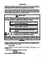
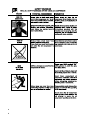
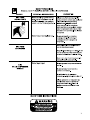
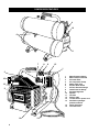
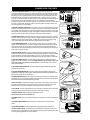
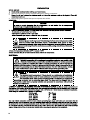
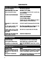
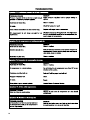
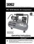
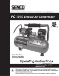
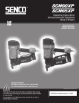
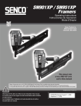
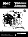
Senco Products Inc.
8485 Broadwell Road
Cincinnati, Ohio 45244
PC1131 Electric
Air Compressor
Operating Instructions
C
US
© 2006, 2007 by Senco Products, Inc.
Warnings for the safe use of this tool are included in this manual.
Questions? Comments?
call SENCO’S toll-free Action-line: 1-800-543-4596
or e-mail: [email protected] Visit our Website www.senco.com
PC1131 Electric Compressor -Revised 11/5/07
(Replaces 10/18/06)
3
4
5
6
7
COMPRESSOR FEATURES
4
10
6
11
7
8
9
15
1
3
5
1
2
3
4
5
6
7
8
9
10
11
12
13
14
16
12
2
15
16
14
13
8
Motor/Pressure Switch
Motor Thermal Overload
Air Intake Filter
Air Compressor Pump
Safety relief valve
Air Tank Drain Valves
Air Tank Pressure Gauge
Outlet Pressure Gauge
Pressure Regulator
Dipstick
Oil Drain
Delivery tube
115 Volt electric power cord
Ventilation openings/
protective shroud
Quick disconnect
Cold start valve
COMPRESSOR FEATURES
1) MOTOR/PRESSURE SWITCH: This switch is used to start or stop the air
compressor. Moving the switch to the "Auto" (On) position will provide automatic power to
the pressure switch which will allow the motor to start when the air tank pressure is below
the factory set "cut-in" pressure. When in the On Position, the pressure switch stops the
motor when the air tank pressure reaches the factory set "cut-out" pressure. For safety
purposes, this switch also has a pressure release valve located below the switch designed
to automatically release compressed air from the air compressor pump head and its
discharge line when the air compressor reaches "cut-out" pressure or is shut off. This allows
the motor to restart freely. Moving the switch to the "Off" position will remove power from
the motor and stop the air compressor.
2) MOTOR THERMAL OVERLOAD: The electric motor has a manual resettable overload
protector. If the motor draws excessive current for any reason, the thermal overload will
cut off power, thus preventing the motor from being damaged. Wait until the motor is cool
before pressing the reset button to begin working again. If multiple reset result in consistent
trips, check service and/or reference extension cord sizing recommendations.
3) AIR INTAKE FILTER: This filter is designed to clean air coming into the pump. To ensure
the pump continually receives a clean, cool, dry air supply this filter must always be clean and
ventilation opening free from obstructions. The filter can be removed for cleaning by using
warm, soapy water. Rinse the filter and air dry. Replace filter when necessary.
4) AIR COMPRESSOR PUMP: To compress air, the piston moves up and down in the
cylinder. On the downstroke, air is drawn in through the air intake valve while the exhaust
valve remains closed. On the upstroke, air is compressed, the intake valve closes and
compressed air is forced out through the exhaust valve, into the discharge line, through the
check valve and into the air tank.
1
3
4
2
8
9
7
5
5) SAFETY RELIEF VALVE: This valve is designed to prevent system failures by relieving
pressure from the system if compressed air reaches a predetermined level. The valve is preset
by the manufacturer and must not be modified in any way. To verify the valve is working
properly, pull on the ring. Air pressure should escape. When the ring is released, it will reseat.
6) AIR TANK DRAIN VALVE: The drain valve is used to remove moisture from the air
tank(s) after the air compressor is shut off. NEVER attempt to open the drain valve when
more than 10 PSI of air pressure is in the air tank! To open the drain valve, turn the
knob counterclockwise.
6
10
7) AIR TANK PRESSURE GAUGE: The air tank pressure gauge indicates the reserve air
pressure in the air tank (s).
11
8) OUTLET PRESSURE GAUGE: The outlet pressure gauge indicates the air pressure
available at the outlet side of the regulator. This pressure is controlled by the regulator and is
always less or equal to the air tank pressure.
9) PRESSURE REGULATOR: The air pressure coming from the air tank is controlled by the
regulator knob. Turn the pressure regulation knob clockwise to increase discharge pressure,
and counterclockwise to decrease discharge pressure.
13
10) OIL DIPSTICK: The dipstick will register the amount of oil in the pump. Oil level should
be checked on a daily basis to ensure that it does not exceed the maximum notch or fall
below the minimum notch on the dipstick. Air escaping from the vent is normal.
14
11) OIL DRAIN: The drain is provided to remove oil that has exceeded its service life. Drain
oil into approved container and dispose of properly. Refill prior to starting.
15
12) RISK OF BURNS Head and discharge lines can be very hot.
Do not touch until unit has cooled after use.
13) POWER CORD: Use only 115VAC 15A service. See extension cord recommendations on
page 10.
14) VENTILATION OPENING: Keep opening free of obstructions to provide maximum
cooling.
16
15) QUICK DISCONNECT: Spring loaded sealed coupling for easy hose removal. 1/4".
16) COLD START VALVE: The compressor is provided with a normally open valve. This
valve will relieve compressed air for a few seconds at compressor start up allowing the motor
to reach operating speed with low pump resistance.
12
2.
3.
Add entire contents of oil from enclosed bottle prior to starting compressor.
4.
Remove plug from cylinder head port and replace with air filter.
10
10
OPERATION
PRE-START CHECKLIST:
1. Check oil level. Add if necessary.
2. Remove any moisture in the air compressor air tank. Remove excessive pressure with an air tool, then open
the air tank drain valve in the bottom of the air tank. Close tightly when drained.
WARNING: Risk of bodily injury. NEVER attempt to open the drain valve when
more than 10 PSI of air pressure is in the air tank!
3.
4.
5.
6.
Make sure the air compressor Motor Switch is in the “OFF” position.
Make sure all safety valves are working correctly.
Make sure all guards and covers are in place and securely mounted.
Make sure that air filter is placed in proper opening. Remove plug before threading housing into compressor.
START-UP:
1. Ensure the lever on the pressure switch box is in the “OFF” position.
2. Plug the power cord into a grounded outlet.
3. Move the lever on the pressure switch box to the “ON” position.
4. START/STOP: Turn to the ON position. This will allow the air compressor to “START” building up pressure in
the air tanks and “STOP” when correct pressure is achieved. When pressure drops with usage, the air
compressor willautomatically “START” building up pressure again.
5. Set pressure by adjusting the pressure regulator knob counterclockwise for less pressure and clockwise for
more pressure.
6. If you notice any unusual noise or vibration, stop the air compressor and refer to “Troubleshooting”.
SHUTDOWN:
1. To stop the air compressor, move the lever on the pressure switch box to the “OFF” position. NEVER stop the
air compressor by unplugging it from the power source. This could result in risk of electrocution.
2. Drain air from the air tanks by releasing air with an attached air tool or by pulling on the safety relief valve rings.
3. Once pressure in the air tanks register under 10 psig, open the drain valve under each air tank to drain any
moisture.
4. Allow the air compressor to cool down.
5. Wipe air compressor clean and store in a safe, non-freezing area.
MAINTENANCE
Read the instruction manual before performing maintenance. The following procedures must be performed when
stopping the air compressor for maintenance or service.
1. Turn off air compressor.
WARNING: Never assume the air compressor is safe to work on just because
it is not operating. It could restart anytime!
2. Disconnect cord from main power supply.
3. Open all drains.
4. Wait for the air compressor to cool before starting service.
MAINTENANCE CHART
PROCEDURE
Check pump oil level
Oil leak inspection
Drain condensation in air tank(s)
Check for unusual noise/vibration
Check for air leaks
Inspect air filter
Clean exterior of compressor
Check safety relief valve
Change pump oil*
Replace air filter
DAILY
X
X
X
X
X
WEEKLY
X
X
MONTHLY
X
200 HOURS
X
X
*The pump oil must be changed after the first 50 hours of operation and every 200 hours or 3 months, whichever
comes first. Recommended non-detergent straight weights.
11
11
ON position, motor runs continuously.
12
12
13
13
14
14
PC1131
2.0 running, 2.5 peak
3400
Oil Capacity
90
12 oz.
3.7
70 seconds
16 seconds
60 lbs
65
Running Duty Type
Noise
20”x14.5”x16.5”
S1 @ 100 psig
79 dBA
15
15
Limited Warranty
SENCO® Pneumatic, DuraSpin®, Cordless Tools
& Compressors
Senco Products, Inc. (“SENCO”) designs and constructs its products using the highest standards of material and workmanship. SENCO
warrants to the original retail purchaser that the following products will be free from defects in material or workmanship for the warranty
period specified below:
SENCO® XP Series-Red Cap
SENCO PRO Series
SENCO Compressors
Five years
One year
One year
SENCO® XP Series-Black Cap SENCO DuraSpin®
SENCO Cordless
Two Years
One year
Two years
SENCO FP502
SENCO Reconditioned Products
Two Years
One Year
During the warranty period (which begins on the purchase date), SENCO will repair or replace, at SENCO’s option and expense, any product or part that
is defective in materials or workmanship after examination by a SENCO Authorized Warranty Service Center, subject to the exceptions, exclusions and
limitations described below. Any replacement product or part will carry a warranty for the balance of the warranty period applicable to the replaced
product or part. A DATED SALES RECEIPT OR PROOF OF PURCHASE FROM THE ORIGINAL RETAIL PURCHASER IS REQUIRED TO MAKE A
WARRANTY CLAIM. Warranty registration also is required and can be accomplished through on-line Product Registration at www.senco.com or by
completing and returning the postage paid warranty registration form included with your Operator’s manual/parts chart information, found inside the
product carton. To make a warranty claim, you must return the product, with proper receipt/proof of purchase and return transportation charges prepaid,
to a SENCO Authorized Warranty Service Center. A list of SENCO Authorized Warranty Service Centers can be found at www.senco.com or by calling
1-800-543-4596 toll free. SENCO will perform its obligations under this warranty, within a reasonable time after approval of the warranty claim.
Wheelbarrow Compressors:
1.
2.
Subject to the exceptions, exclusions and limitations described below, SENCO warrants that the compressor pump will be free from defects in
materials and workmanship for two years after the purchase date.
Defective parts of the compressor pump not subject to normal wear and tear will be repaired or replaced, at SENCO's option, during the two
year warranty period. If SENCO determines that repair or replacement is not feasible, SENCO will refund the purchase price less reasonable
depreciation based on actual use.
SENCO Cordless:
1.
2.
Subject to the exceptions, exclusions and limitations described below, SENCO warrants that the SENCO Cordless tool will be free from
defects in materials and workmanship for two years after the purchase date.
Subject to the exceptions, exclusions and limitations described below, SENCO warrants that the batteries and chargers used with SENCO
Cordless tools will be free from defects in material and workmanship for one year after the purchase date.
WARRANTY EXCLUSIONS
The following warranty exclusions apply:
1. Normal wear parts are not covered under this warranty. Normal wear parts include, for example, isolators, drive belts, air filters, rubber o-rings,
seals, driver blades, piston stops, and piston/driver assembly.
2. This warranty does not cover parts damaged due to normal wear, misapplication, misuse, accidents, operation at other than recommended
speeds or voltage (electric units only), improper storage, or damage resulting during shipping.
3. Products used in production/industrial applications as defined by SENCO are excluded from this warranty.
4. Labor charges or loss or damage resulting from improper operation, maintenance or repairs are not covered by this warranty.
5. SENCO does not warrant the Wheelbarrow Compressor Engine/Motor, but the Compressor Engine/Motor may be covered under a warranty
offered by its manufacturer.
GENERAL WARRANTY CONDITIONS
This warranty will be honored, only if:
A. Clean, dry, regulated compressed air has been used, at air pressure not exceeding the maximum indicated on the tool casting;
B. No evidence of abuse, abnormal conditions, accident, neglect, misuse or improper modifications or storage of the product; and
C. No Deviation from operating instructions, specifications, and maintenance schedules exists (read Operator Manual for use, specifications, and
maintenance instructions).
THIS WARRANTY IS THE ONLY WARRANTY ON THE PRODUCT, AND SENCO DISCLAIMS ALL OTHER WARRANTIES. ANY IMPLIED
WARRANTIES WILL BE LIMITED IN DURATION TO THE APPLICABLE WARRANTY PERIOD SPECIFIED ABOVE. SOME STATES DO NOT ALLOW
LIMITATIONS ON HOW LONG AN IMPLIED WARRANTY LASTS, SO THE ABOVE LIMITATION MAY NOT APPLY TO YOU. YOUR REMEDIES ARE
SOLELY AND EXCLUSIVELY AS STATED ABOVE. SENCO SHALL IN NO EVENT BE LIABLE FOR INCIDENTAL, CONSEQUENTIAL, INDIRECT,
OR SPECIAL DAMAGES. SOME STATES DO NOT ALLOW THE EXCLUSION OR LIMITATION OF INCIDENTAL OR CONSEQUENTIAL DAMAGES,
SO THE ABOVE LIMITATION OR EXCLUSION MAY NOT APPLY TO YOU. IN NO EVENT, WHETHER AS A RESULT OF A BREACH OF
CONTRACT, WARRANTY, TORT (INCLUDING NEGLIGENCE) OR OTHERWISE, SHALL SENCO’S LIABILITY EXCEED THE PRICE OF THE
PRODUCT WHICH HAS GIVEN RISE TO THE CLAIM OR LIABILITY. ANY LIABILITY CONNECTED WITH THE USE OF THIS PRODUCT SHALL
TERMINATE UPON THE EXPIRATION OF THE WARRANTY PERIOD SPECIFIED ABOVE. NO EMPLOYEE OR REPRESENTATIVE OF SENCO OR
ANY DISTRIBUTOR OR DEALER IS AUTHORIZED TO MAKE ANY CHANGE OR MODIFICATION TO THIS WARRANTY.
This warranty gives you specific legal rights, and you may also have other rights which vary from state to state.
REPLACEMENT OF TOOL DUE TO NATURAL DISASTER
SENCO will replace any tool destroyed by an Act of God such as flood, earthquake, hurricane or other disaster resulting only from the forces of nature.
Such a claim will be honored provided that such original retail purchaser had previously submitted a completed warranty registration card for the tool,
and then submits proof of ownership and an acceptable statement describing such Act of God documented by an insurance carrier, police department,
or other official governmental source. To obtain instructions for filing a claim call 1-800-543-4596.
CUSTOMER SATISFACTION
One hundred percent customer satisfaction is our #1 goal. If for any reason the product does not perform to the original purchaser’s satisfaction, it can
be returned to the place of purchase within thirty days with dated sales receipt for a full refund of the purchase price.
©2006, 2007 by SENCO PRODUCTS, INC.
CINCINNATI, OHIO 45244-1611 USA
www.senco.com
070607