1
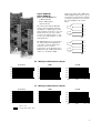
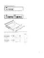
Agilent 34970A
Data Sheet
This document lists specifications for
the Agilent Technologies 34970A Data
Acquisition/Switch Unit and its modules. The explanations and examples
below are helpful in understanding
how to interpret these specifications:
• Measurement accuracy is specified
as percent of reading plus percent
of range, where reading is the actual measured value and range is the
name of the scale (1V, 10V, etc)—not
the full scale value (1.2V, 12V, etc.).
• DMM measurement accuracies
include all switching errors.
Switching errors are also listed separately in the module specifications
section. Temperature measurement
accuracies include ITS-90 conversion errors. The thermocouple accuracies include the reference junction error as well.
• Accuracies are listed as either
24-hour, 90-day, or 1-year specifications. This refers to the length of
time since the instrument’s last calibration. Use the specification that
matches your calibration cycle. The
24-hour specifications are useful for
determining short-term relative
performance.
EXAMPLE 1: Basic dcV accuracy
Calculate the accuracy of the
following measurement:
9 V dc input
10 V dc range
1 year accuracy specifications
Normal operating temperature
(18°C - 28°C)
From the following page, the 1-year
accuracy is
0.0035% of reading + 0.0005%
of range,
which translates into
(0.0035/100 x 9 V) +
(0.0005/100 x 10 V) = 365µV,
for a total accuracy of
365 µV / 9 V = 0.0041%.
For this example, assume a J-type
thermocouple input reading 150°C.
From the following page, total error is
Thermocouple probe accuracy
+ 1.0 °C.
EXAMPLE 2: Extreme operating
temperature
The probe vendor specifies accuracy
of 1.1°C or 0.4 %, whichever is
greater.
When the 34970A is used outside
of its 18ºC-28ºC temperature range,
there are additional temperature drift
errors to consider. Assume the same
conditions in example 1, but at a 35°C
operating temperature:
Total error is then
1.0°C + 1.1°C = 2.1°C total,
or 1.4%.
The basic accuracy is again
0.0035% of reading + 0.0005% of
range=365 µV.
Now, multiply the 10 V temperature
coefficient from the following page by
the number of degrees outside of operating range for additional error:
(0.0005% reading + 0.0001%
range)/°C x (35°C - 28°C) =
(0.0005% reading + 0.0001%
range)/°C x 7°C =
0.0035% reading + 0.0007% range =
385 µV.
Total error is then
365 µV + 385 µV = 750 µV or
0.008%.
EXAMPLE 3: Thermocouple
measurement accuracy
Calculating the total thermocouple
reading error is easy with the 34970A—
just add the listed measurement accuracy to the accuracy of your transducer.
Switching, conversion, and reference
junction errors are already included in
the measurement specification.
EXAMPLE 4: acV accuracy
The acV function measures the true
RMS value of the input waveform,
regardless of waveshape. Listed
accuracies assume a sinewave input.
To adjust accuracies for non-sinusoids,
use the listed crest factor adder.
For this example, assume a ±1 V
square wave input with 50% duty cycle
and a 1 kHz frequency.
Accuracy for 1 V, 1 kHz sinusoid is
0.06% reading + 0.04% range.
A 50% duty cycle squarewave has a
crest factor of
Peak Value / RMS value =
1V/1V=1
From Crest Factor table, add
0.05% of reading.
The total accuracy is
0.11% of reading + 0.04% of
range = 1.5 mV or 0.15%.
Accuracy Specifications ±(% of reading + % of range)[1]
Includes measurement error, switching error, and transducer conversion error
Frequency,
etc.
Range[3]
24 Hour [2]
23°C ± 1°C
90 Day
23°C ± 5°C
1 Year
23°C ± 5°C
Temperature
Coefficient
0°C – 18°C
28°C – 55°C
0.0030 + 0.0035
0.0020 + 0.0006
0.0015 + 0.0004
0.0020 + 0.0006
0.0020 + 0.0020
0.0040 + 0.0040
0.0030 + 0.0007
0.0020 + 0.0005
0.0035 + 0.0006
0.0035 + 0.0030
0.0050 + 0.0040
0.0040 + 0.0007
0.0035 + 0.0005
0.0045 + 0.0006
0.0045 + 0.0030
0.0005 + 0.0005
0.0005 + 0.0001
0.0005 + 0.0001
0.0005 + 0.0001
0.0005 + 0.0003
dc Voltage
100.0000 mV
1.000000 V
10.00000 V
100.0000 V
300.000 V
True rms
ac Voltage[4]
100.0000 mV
to 100.0000V
3 Hz - 5 Hz
5 Hz - 10 Hz
10 Hz - 20 kHz
20 kHz - 50 kHz
50 kHz - 100 kHz
100 kHz - 300 kHz[5]
1.00 + 0.03
0.35 + 0.03
0.04 + 0.03
0.10 + 0.05
0.55 + 0.08
4.00 + 0.50
1.00 + 0.04
0.35 + 0.04
0.05 + 0.04
0.11 + 0.05
0.60 + 0.08
4.00 + 0.50
1.00 + 0.04
0.35 + 0.04
0.06 + 0.04
0.12 + 0.05
0.60 + 0.08
4.00 + 0.50
0.100 + 0.004
0.035 + 0.004
0.005 + 0.004
0.011 + 0.005
0.060 + 0.008
0.20 + 0.02
300.0000V
3 Hz - 5 Hz
5 Hz - 10 Hz
10 Hz - 20 kHz
20 kHz - 50 kHz
50 kHz - 100 kHz
100 kHz - 300 kHz[5]
1.00 + 0.05
0.35 + 0.05
0.04 + 0.05
0.10 + 0.10
0.55 + 0.20
4.00 + 1.25
1.00 + 0.08
0.35 + 0.08
0.05 + 0.08
0.11 + 0.12
0.60 + 0.20
4.00 + 1.25
1.00 + 0.08
0.35 + 0.08
0.06 + 0.08
0.12 + 0.12
0.60 + 0.20
4.00 + 1.25
0.100 + 0.008
0.035 + 0.008
0.005 + 0.008
0.011 + 0.012
0.060 + 0.020
0.20 + 0.05
1 mA current source
1 mA
100 µA
10 µA
5.0 µA
500 nA
500 nA/10 MΩ
0.0030 + 0.0035
0.0020 + 0.0006
0.0020 + 0.0005
0.0020 + 0.0005
0.002 + 0.001
0.015 + 0.001
0.300 + 0.010
0.008 + 0.004
0.008 + 0.001
0.008 + 0.001
0.008 + 0.001
0.008 + 0.001
0.020 + 0.001
0.800 + 0.010
0.010 + 0.004
0.010 + 0.001
0.010 + 0.001
0.010 + 0.001
0.010 + 0.001
0.040 + 0.001
0.800 + 0.010
0.0006 + 0.0005
0.0006 + 0.0001
0.0006 + 0.0001
0.0006 + 0.0001
0.0010 + 0.0002
0.0030 + 0.0004
0.1500 + 0.0002
3 Hz - 5 Hz
5 Hz - 10 Hz
10 Hz - 40 Hz
40 Hz - 300 kHz
0.10
0.05
0.03
0.006
0.10
0.05
0.03
0.01
0.10
0.05
0.03
0.01
0.005
0.005
0.001
0.001
Resistance[6]
Frequency
or Period[7]
100.0000Ω
1.000000 kΩ
10.00000 kΩ
100.0000 kΩ
1.000000 MΩ
10.00000 MΩ
100.0000 MΩ
100 mV
to
300 V
dc Current
(34901A only)
10.00000 mA
100.0000 mA
1.000000 A
<0.1 V burden
<0.6V
<2 V
0.005 + 0.010
0.010 + 0.004
0.050 + 0.006
0.030 + 0.020
0.030 + 0.005
0.080 + 0.010
0.050 + 0.020
0.050 + 0.005
0.100 + 0.010
0.002+ 0.0020
0.002 + 0.0005
0.005 + 0.0010
True rms
ac Current
(34901A only)
10.00000 mA
and[4]
1.000000 A
3 Hz - 5 Hz
5 Hz - 10 Hz
10 Hz - 5 kHz
1.00 + 0.04
0.30 + 0.04
0.10 + 0.04
1.00 + 0.04
0.30 + 0.04
0.10 + 0.04
1.00 + 0.04
0.30 + 0.04
0.10 + 0.04
0.100 + 0.006
0.035 + 0.006
0.015 + 0.006
100.0000 mA[8]
3 Hz - 5 Hz
5 Hz - 10 Hz
10 Hz - 5 kHz
1.00 + 0.5
0.30 + 0.5
0.10 + 0.5
1.00 + 0.5
0.30 + 0.5
0.10 + 0.5
1.00 + 0.5
0.30 + 0.5
0.10 + 0.5
0.100 + 0.06
0.035 + 0.06
0.015 + 0.06
Temperature
Thermocouple
RTD
Thermistor
Type
1-Year Accuracy[9]
Extended Range 1-Year Accuracy[9]
B
E
J
K
N
R
S
T
-1100°C to 1820°C
-150°C to 1000°C
-150°C to 1200°C
-100°C to 1200°C
-100°C to 1300°C
-300°C to 1760°C
-400°C to 1760°C
-100°C to 400°C
1.2°C
1.0°C
1.0°C
1.0°C
1.0°C
1.2°C
1.2°C
1.0°C
R0 from 49 Ω to 2.1 kΩ
-200°C to 600°C
0.06°C
2.2 k, 5k, 10k
-80°C to 150°C
0.08°C
[1] Specifications are for 1 hr warm-up and 61/2 digits, Slow ac filter
[2] Relative to calibration standards
[3] 20% over range on all ranges except 300 Vdc and ac ranges and 1 Adc and ac current ranges
[4] For sinewave input > 5% of range. For inputs from 1% to 5% of range and < 50 kHz,
add 0.1% of range additional error
2
-400°C to 1100°C
-200°C to -150°C
-210°C to -150°C
-200°C to -100°C
-200°C to -100°C
-50°C to 300°C
-50°C to 400°C
-200°C to -100°C
1.8°C
1.5°C
1.2°C
1.5°C
1.5°C
1.8°C
1.8°C
1.5°C
Temperature Coefficient
0°C – 18°C, 28°C – 55°C
0.03 °C
0.003°C
0.002°C
[5] Typically 30% of reading error at 1 MHz, limited to 1 x 10⁸ V Hz
[6] Specifications are for 4- wire ohms function or 2-wire ohms using Scaling to remove
the offset. Without scaling, add 1 Ω additional error in 2-wire Ohms function
[7] Input > 100 mV. For 10 mV inputs multipy % of reading error x 10
[8] Specified only for inputs >10 mA
[9] For total measurement accuracy, add temperature probe error
Measurement Characteristics[8]
Operating Characteristics[4]
DC Voltage
Measurement Method:
Single Channel Measurement Rates[5]
Function
Resolution[9]
dcV, 2-wire Resistance
61/2 digits (10 plc)
51/2 digits (1 plc)
41/2 digits (0.02 plc)
Thermocouple
0.1°C (1 plc)
(0.02 plc)
RTD, Thermistor
0.01°C (10 plc)
0.1°C (1 plc)
1°C (0.02 plc)
acV
61/2 Slow (3 Hz)
61/2 Med (20 Hz)
61/2 Fast (200 Hz)
61/2 [6]
Frequency, Period
61/2 digits (1s gate)
51/2 digits (100 ms)
41/2 digits (10 ms)
Reading/s
6 (5)
57 (47)
600
57 (47)
220
6 (5)
57 (47)
220
0.14
1
8
100
1
9
70
System Speeds[7]
INTO Memory
Single Channel dcV
34902A Scanning dcV
34907A Scanning Digital in
34902A Scanning dcV with Scaling & 1 Alarm Fail
34907A Scanning Totalize
34902A Scanning Temperature
34902A Scanning acV[6]
34902A Scanning dcV/Ohms on Alternate Channels
34901A/34908A Scanning dcV
ch/s
600
250
250
220
170
160
100
90
60
INTO and OUT of Memory to GPIB or RS-232 (init, fetch)
34902A Scanning dcV
34902A Scanning dcV with Timestamp
180
150
OUT of Memory to GPIB
Readings
Readings with Timestamp
Readings with All Format Options ON
800
450
310
OUT of Memory to RS-232
Readings
Readings with Timestamp
Readings with All Format Options ON
600
320
230
DIRECT to GPIB or RS-232
Single Channel dcV
34902A Scanning dcV
Single Channel MEAS DCV 10 / MEAS DCV 1
Single Channel MEAS DCV/ MEAS OHMS
440
200
25
12
A-D Linearity:
Input Resistance:
100 mV, 1 V, 10 V ranges
100V, 300V ranges
Input Bias Current:
Input Protection:
True RMS AC Voltage
Measurement Method:
Crest Factor:
Additional Crest Factor
Errors (non-sinewave):
Input Impedance:
Input Protection:
Resistance
Measurement Method:
Offset Compensation:
Maximum Lead Resistance:
Input Protection:
Continuously Integrating Multi-slope
IIIA-D Converter
0.0002% of reading + 0.0001 % of range
Selectable 10 MΩ or > 10,000 MΩ
10 MΩ ± 1%
< 30 pA at 25°C
300 V all ranges
AC coupled True RMS — measures the
AC component of the input with up to
300 Vdc of bias on any range
Maximum of 5:1 at Full Scale
Crest Factor 1-2
0.05 % of reading
Crest Factor 2-3
0.15 % of reading
Crest Factor 3-4
0.30 % of reading
Crest Factor 4-5
0.40 % of reading
1 MΩ ± 2% in parallel with 150 pF
300 Vrms all ranges
Selectable 4-wire or 2-wire Ohms
Current source referenced to LO input
Selectable on 100Ω, 1kΩ, 10kΩ ranges
10% of range per lead for 100 Ω and
1 kΩ ranges. 1 kΩ on all other ranges
300 V on all ranges
Frequency and Period
Measurement Method:
Voltage Ranges:
Gate Time:
Measurement Timeout:
Reciprocal counting technique
Same as AC Voltage function
1s, 100 ms, or 10 ms
Selectable 3Hz, 20Hz, 200Hz LF limit
DC Current
Shunt Resistance:
Input Protection:
5 Ω for 10 mA, 100 mA; 0.1 Ω for 1 A
1A 250V fuse on the 34901A module
True RMS AC Current
Measurement Method:
Shunt Resistance:
Input Protection:
Direct coupled to the fuse and shunt.
AC coupled True RMS measurement
(measures the ac component only)
5 Ω for 10 mA; 0.1 Ω for 100 mA, 1 A
1A 250V fuse on the 34901A module
Thermocouple
Conversion:
Reference Junction Type:
Open Thermocouple Check:
ITS-90 software compensation
Internal, Fixed, or External
Selectable per channel. Open >5kΩ
Thermistor
44004, 44007, 44006 series
RTD
α = 0.00385 (DIN) and α = 0.00392
Measurement Noise Rejection 60 (50) Hz[1]
dc CMRR:
140 dB
ac CMRR:
70 dB
Integration Time
200 plc / 3.33s (4s)
100 plc / 1.67s (2s)
20 plc / 333 ms (400 ms)
10 plc / 167 ms (200 ms)
2 plc / 33.3 ms (40 ms)
1 plc / 16.7 ms (20 ms)
< 1 plc
[1] For 1 KΩ unbalance in LO lead
[2] For power line frequency ±0.1%
[3] For power line frequency ±1% use 80 dB or ±3% use 60 dB
[4] Reading speeds for 60 Hz and (50 Hz) operation
[5] For fixed function and range, readings to memory, scaling and alarms off, AZERO
OFF
[6] Maximum limit with default settling delays defeated
[7] Speeds are for 41/2 digits, delay Ø, display off, autozero off. Using 115 kbaud RS-232
setting
[8] Isolation voltage (ch - ch, ch - earth) 300 Vdc, ac rms
[9] 61/2 digits = 22 bits, 51/2 digits = 18 bits, 41/2 digits = 15 bits
Normal Mode Rejection[2]
110 dB [3]
105 dB [3]
100 dB [3]
95 dB [3]
90 dB
60 dB
0 dB
3
System Characteristics
Software
Scanning Inputs
Analog
HP BenchLink Data Logger (not included with Option 001)
Digital
Scan List
Scan Triggering
Source
Scan Count
Scan Interval
Channel Delay
External Trig Delay
External Trig Jitter
Alarms
Analog Inputs
Digital Inputs
Monitor Channel
Alarm Outputs
Latency
Agilent 34901A, 34902A, and 34908A
multiplexer channels
34907A digital in and totalize
Scans channels in ascending order
Interval, external, button press, software,
or on monitor channel alarm
1 to 50,000 or continuous
0 to 99 hours; 1ms step size
0 to 60 seconds per channel; 1 ms step size
<2 ms. With monitor on <200 ms
<2 ms
Hi, Lo, or Hi + Lo evaluated each scan
34907A digital in: maskable pattern
match or state change
34907A totalize: Hi limit only
Alarm evaluated each reading
4 TTL compatible
Selectable TTL logic Hi or Lo on fail
5 ms (typical)
System Requirements[2]
PC Hardware
Operating System
Instrument Support
Computer Interfaces[3]
GPIB
LAN -to- GPIB
RS-232 (Serial Port)
HP BenchLink Features
Configuration
States
Alarm Queue
System Features
Per-channel Math
Power Fail Recovery
Relay Maintenance
Real Time Clock
General Specifications
Power Supply
Power Line Frequency
Power Consumption
Operating Environment
Storage Environment
Weight
Safety
RFI and ESD
Warranty
Battery backed, 4 year typical life[1]
50,000 with timestamp
Readable during scan
5 instrument states with user label
Up to 20 events with channel number, reading, and timestamp
Individual Mx + B scaling and
Min/Max/Average calculated real time
Resumes scanning automatically
Counts each relay closure and stores
on module
User resettable.
Battery-backed, 4 year typical life[1]
100V / 120V / 220V / 240V ±10%
45 Hz to 66 Hz automatically sensed
12 W (25 VA peak)
Full accuracy for 0°C to 55°C
Full accuracy to 80% R.H. at 40°C
-40°C to 70°C[1]
Net: 3.6 kg (8.0 lbs)
Conforms to CSA, UL-1244, IEC 1010 Cat I
CISPR 11, IEC 801/2/3/4
3 years
[1] Storage at temperatures above 40°C will decrease battery life
[2] Software provided on CD-ROM and includes utility to create floppy disks
for installation
[3] Interface and driver must be purchased and installed separately
[4] 90 MHz Pentium, 20 MB RAM
[5] Requires VISA command library for IEEE-488
Windows, Windows 95, and Windows NT are registered trademarks of Microsoft Corp.
LabVIEW is a registered trademark of National Instruments Corporation.
4
82335B, 82340A/B/C, 82341A/B/C/D
National Instruments AT-GPIB/TNT,
PCI-GPIB, PC-MCIA
E2050A (Windows 95 and NT only)
PC COM 1-4
Spreadsheet-like setup page
Upload and Download intrument setups
Computed channels using _
+ - * / , dB, dBm, dBV, x2, √x
and full, 1/2, or 1/4 bridge strain
Graphical Displays
Real-time and historical data displays
Add, delete, size, and configure real time
Strip chart with markers and alarm indication, X-Y chart with curve fit, Histogram with
statistics, Bar meter, Digital meter, and Data
table
Graphical Controls
Sliders, switches, buttons, and LED lights
Alarm / Limit Testing
Start / Stop scanning on alarm condition
Control 34903A relay state or 34907A digital
output on alarm
Data
Real time streamed (saved) to disk
Copy data or graphics to windows clipboard
Export user-selected data to ASCII file,
CSV, TSV
Event Logging
Automatic entry of alarms and errors
Enter user notes real time
Printing
Setup spreadsheet, all graphics, and event
log entries
Memory
Readings
486, 66 MHz, 16 MB RAM, 12 MB
disk space
Windows® 3.1,Windows 95®,
Windows NT 4.0®
Single 34970A operation
Single program window
HP BenchLink Performance[4]
Scan and Save to Disk
100 ch/s 2 strip charts displayed
Readings Saved
Maximum 150M/file
Instrument Driver Support for Programming Languages
Universal
Compatible with Windows 95 and NT
Agilent VEE 3.2 or greater
Instrument Driver[5]
Visual Basic 4.0,
LabWindows CVI 4.0,
LabVIEW 4.0
Labview Driver (VI)
LabVIEW 4.0
Module Specifications
Up to three modules, in any combination, can be inserted into a single
mainframe. The 34970A's internal
DMM connections are accessible only
through the 34901A, 34902A, and
34908A low-frequency multiplexers.
The Agilent 34970A accuracy specifications already include the switching
offset and reference junction errors
shown below. These errors are listed
separately for determining system
error with external measurement
devices.
Multiplexer
On-module screw terminals accept
wire sizes from 16 gage to 22 gage. 20
gage wire is recommended for high
channel count applications. The
34905A and 34906A RF Multiplexers
use SMB connectors. A standard set
of (10) BNC-to-SMB adapter cables is
provided with each RF module for
convenient BNC connections.
Actuator
Matrix
RF Multiplexer
Multifunction
34905A 34906A
Dual 1 x 4
50 Ω
75 Ω
34907A
See
Page 22
for module
specifications
34901A
20 + 2
2/4 wire
•
60 ch/s
120/s
34902A[1]
16
2/4 wire
•
250 ch/s
120/s
34908A
40
1 wire
•
60 ch/s
70/s
34903A
20
SPDT
34904A
4x8
2 wire
120/s
120/s
60/s
INPUT
Voltage (dc, ac rms)[2]
Current (dc, ac rms)
Power (W, VA)
300V
1A
50W
300V
50mA
2W
300V
1A
50W
300V
1A
50W
300V
1A
50W
42
0.7A
20W
DC Characteristics
Offset Voltage [3]
Initial Closed Channel R [3]
Isolation ch-ch, ch-earth
< 3uV
< 6uV
<1Ω
<1Ω
> 10 G Ω > 10 G Ω
< 3uV
<1Ω
> 10 G Ω
< 3uV
< 3uV
< 0.2 Ω
<1Ω
> 10 G Ω > 10 G Ω
10 MHz
10 MHz
10 MHz
GENERAL
Number of Channels
Connects to Internal DMM
Scanning Speed
Open/Close Speed
AC Characteristics
Bandwidth[4]
Insertion Loss (dB)
< 6uV
< 0.5 Ω
>1GΩ
10 MHz
100 MHz
500 MHz
1 GHz
1.5 GHz
2 GHz
2 GHz [5]
-0.1
-0.4
-0.6
-1
-1.2
-3
2 GHz [5]
-0.1
-0.4
-0.5
-1
-1.5
-2
SWR
10 MHz
100 MHz
500 MHz
1 GHz
1.5 GHz
2 GHz
1.02
1.05
1.20
1.20
1.30
1.40
1.02
1.05
1.25
1.40
1.40
2.00
ch-ch Cross Talk (dB)[4]
10 MHz
100 MHz
500 MHz
1 GHz
1.5 GHz
2 GHz
-100
-85
-65
-55
-45
-35
-85
-75
-65
-50
-40
-35
Risetime
Signal Delay
Capacitance
HI - LO
LO - Earth
Volt-Hertz limit
OTHER
T/C Cold Junction Accuracy[3] (typical)
Switch Life
No Load (typical)
Rated Load (typical)[7]
Temperature
Humidity
-45
10 MHz
-45
-18[6]
-45
10 MHz
-33
< 50 pF
< 80 pF
108
< 50 pF
< 80 pF
108
< 50 pF
< 80 pF
108
< 10 pF
< 80 pF
108
< 50 pF
< 80 pF
108
0.8°C
100M
100k
0.8°C
100M
100k
0.8°C
100M
100k
100M
100k
100M
100k
Operating
Storage
(non-condensing)
[1] Not recommended for connection to ac line without external transient suppression
[2] Channel-to-channel or channel-to-earth
[3] Errors included in DMM measurement accuracy specifications
[4] 50Ω source, 50Ω load
< 300 ps
< 3 ns
< 20 pF
—
1010
5M
100k
5M
100k
all cards — 0°C to 55°C
all cards — -20°C to 70°C
all cards — 40°C / 80% RH
[5] Bandwidth direct to card SMB connectors
[6] Isolation within channel 1 to 20 or 21 to 40 banks is -40 dB
[7] Applies to resistive loads only
5
Multiplexer Selection Guide
Choose between the broad functionality of the 34901A, the high speed
scanning of the 34902A, or the singleended density of the 34908A. These
three modules are the only way to
connect to the 34970A internal DMM.
They can be used to scan with external instruments as well.
All multiplexer modules employ
break-before-make scanning, ensuring
only one closed channel (or channel
pair) at a time. Multiple channel closures are allowed on the 34901A and
34902A modules when not configured
for scanning.
Number of Channels
Max scan speed
Number of contacts
34901A
34902A
34908A
20 + 2
60 ch/s
2 or 4
16
250 ch/s
2 or 4
40
60 ch/s
1
•
•
•
•
•
•
•
•
•
•
•
•
•
•
•
•
•
•
•
•
•
•
•
•
Temperature
Thermocouple
2-wire RTD
4-wire RTD
Thermistor
dc Volts
ac Volts
2-wire Ohms
4-wire Ohms
Frequency
Period
dc current
ac current
•
•
•
•
•
•
The 34908A does not allow multiple
channel closures at any time.
Agilent 34901A
20-Channel
General-Purpose Multiplexer
• 60 ch/s scanning
• Two- and four-wire scanning
Backplane Switches
Channel Switches
H
L
Internal
DMM Input
• Built-in thermocouple reference
junction
The 34901A is the most versatile multiplexer for general purpose scanning.
It combines dense,
multi-function switching with
60 channel/second scan rates to
address a broad spectrum of data
acquisition applications.
Two- and four-wire channels can
be mixed on the same module.
Two additional fused inputs (22 channels total) route up to 1A of current
to the internal DMM, allowing ac and
dc current measurements without the
need for external shunt resistors.
6
01
H
L
10
H
L
T
• 300 V switching
H
L
H
L
Reference
Junction
Sensor
H
L
Internal
DMM Input
(4W Sense)
Com
Bank Switch
H
L
Com
(4W Sense)
11
H
L
20
I
L
21
Shunt Switches
Fuse
I
L
Internal
DMM Input
(Current)
Current
Channels
Fuse
I
L
22
I
L
Com
(Current)
Agilent 34902A
16-Channel
High-Speed Multiplexer
• 250 ch/s scanning
• Two- and four-wire scanning
• Built-in thermocouple reference
junction
The 34902A employs reed relays to
achieve scan rates up to 250 channels-per-second. Use this module for
high-throughput automated test
applications as well as high-speed
data logging and monitoring tasks.
Sixteen two-wire inputs switch up to
300 V. Two- and four-wire channels
may be mixed on the same module.
User provided shunt resistors are
required for current measurements.
Backplane Switches
H
L
Internal
DMM Input
T
Channel Switches
H
L 01
H
L 08
H
L Com
Bank Switch
H Com
L (4W Sens
H
L 09
Reference
Junction
Sensor
H
L
Internal
DMM Input
(4W Sense)
H
L 16
Note: Not recommended for connection to
ac line without external transient suppression.
Agilent 34908A
Channel Switches
H 01
40-Channel
Single-Ended Multiplexer
• 60 ch/s scanning
• Single-wire switching for commonlow applications
• Built-in thermocouple
reference junction
H 20
H Com
Backplane
Switch
H
L
Internal
DMM Input
L Com
Bank Switch
H 21
Use the 34908A for the greatest density in common-low applications,
such as battery test, component characterization, and benchtop testing.
Each module switches 40 one-wire
inputs. All two-wire internal measurements except current are supported.
The module low connection is isolated
from earth and can float up to 300V.
H 40
T
Reference
Junction
Sensor
Note: Thermocouples must be electrically isolated from each other to avoid current loops and
subsequent measurement errors.
7
Agilent 34903A
20-Channel Actuator/
General Purpose Switch
• SPDT (Form C) latching relays
NC
• 300 V, 1 A actuation and control
COM
This general-purpose switch module
has 20 independent single-pole, double-throw (SPDT) relays. Use it to
cycle power to products under test,
control indicator and status lights,
and to actuate external power relays
and solenoids. Combine it with
matrix and multiplexer modules to
build custom switch systems. Its
300V, 1A contacts can handle up to
50W, enough for many power line
switching applications.
Agilent 34904A
4x8 Two-wire Matrix Switch
• 32 two-wire crosspoints
NC
COM
20
NO
Col 1
H L
Col 2
H L
Col 8
H L
H
Row 1
L
• 300V, 1A switching
The 34904A gives you the most flexible connection path between your
device under test and your test
equipment, allowing different instruments to be connected to multiple
points on your DUT at the same time.
Rows or columns may be connected
between multiple modules to build
8x8, 4x16 or larger matrices, with up
to 96 crosspoints in a single frame.
01
NO
H
L Row 2
H
Row 3
L
H
Row 4
L
H
L
H
L
8
Channel 31
(Row 3, Column 1)
adapters provided with 1 GHz bandwidth. Multiple banks may be cascaded together for applications requiring
even larger topologies—create a stubless 16:1 multiplexer in a single
frame.
Agilent 34905A 50Ω
Agilent 34906A 75Ω
Dual 4-channel RF Multiplexers
• 2 GHz bandwidth
• BNC to SMB adapter
cables included
11
The 34905A and 34906A RF multiplexers offer broadband switching
capabilities for high-frequency and
pulsed signals. Use them to route test
signals between your device under
test and your signal generator, oscilloscope, spectrum analyzer, or other
instrumentation.
12
Com
13
14
21
The RF multiplexers are arranged as
two independent 1x4 multiplexers,
each with a common shield and a
switched center conductor.
Connections can be made directly to
SMB inputs with 2 GHz usable bandwidth, or to the BNC-to-SMB
22
Com
23
24
50Ω MUX Typical AC Performance Graphs
Insertion Loss
VSWR
0 dB
1.80
-1 dB
1.60
-2 dB
1.40
-3 dB
1.20
-4 dB
1.00
10 MHz
100 MHz
1 GHz
3 GHz
10 MHz
Crosstalk
-20 dB
-40 dB
-60 dB
-80 dB
-100 dB
100 MHz
1 GHz
3 GHz
10 MHz
100 MHz
1 GHz
3 GHz
1 GHz
3 GHz
75Ω MUX Typical AC Performance Graphs
Insertion Loss
VSWR
0 dB
1.80
-1 dB
1.60
-2 dB
1.40
-3 dB
1.20
-4 dB
1.00
Crosstalk
-20 dB
-40 dB
-60 dB
-80 dB
10 MHz
100 MHz
1 GHz
3 GHz
10 MHz
-100 dB
100 MHz
1 GHz
3 GHz
10 MHz
100 MHz
direct to card
using provided adapter cables
9
Agilent 34907A
Bit 0
Multifunction Module
• 16 bits of digital input and output
8
Port 1
Channel 01
• 100 kHz totalizer input
• Two ±12V analog outputs
The 34907A allows great flexibility
for a variety of sense and control
applications. It combines two 8-bit
ports of digital input and output, a
100 kHz gated totalizer, and two ±12V
analog outputs—all on a single earthreferenced module. The digital inputs
and totalizer input may be included
in a scan. Alarm limits for the digital
and event counter inputs are evaluated continuously, capturing and logging alarm conditions even between
scans.
DIO
Bit 7
Bit 0
8
Port 2
Channel 02
Bit 7
+IN
-IN
28 Bits
Channel 03
TOT
Gate
Gate
16
DAC 1
Channel 04
DAC 2
Channel 05
16
Digital Input/Ouput
Totalize Input
Analog Output
Use the digital outputs with an external power supply to control microwave
switches and attenuators, solenoids,
power relays, indicators, and more.
Use the digital inputs to sense limit
switch and digital bus status. There
are no complex handshake modes;
reads and writes are initiated either
from the front panel or the bus.
Count events from devices like photo
interrupters, limit switches, and
Hall-effect sensors.
Use the two electronically calibrated
analog outputs to source bias voltages
to your device under test, to control
your analog programmable power
supplies, or use the outputs as setpoints for your control systems. The
outputs are programmed directly in
volts, either from the front panel or
from the bus.
It keeps an updated total which can
be read via the front panel or programmatically at any time. With 26
bits of resolution, it can count events
at full speed for nearly 11 minutes
without an overflow.
Analog Output
Digital Input/Output
Totalize Input
Port 1, 2
Vin(L)
Vin(H)
Vout(L)
Vout(H)
Vout(H) max
Alarming
Speed
Latency
Read/Write Speed
10
8 bit, input or output, nonisolated
< 0.8V (TTL)
> 2.0V (TTL)
< 0.8V @ Iout = - 400 mA
> 2.4V @ Iout = 1 mA
< 42V with external open
drain pull-up
Maskable pattern match
or state change
4 ms (max) alarm
sampling
5 ms (typical) to 34970A
alarm output
95/s
Max Count
Totalize Input
Signal level
Threshold
Gate Input
Count Reset
Read Speed
226 - 1
100 kHz (max)
Rising or falling edge,
programmable
1 Vp-p (min)
42 Vpk (max)
0V or TTL,
jumper selectable
TTL-Hi, TTL-Lo, or none
Manual or Read + Reset
85/s9
DAC 1, 2
Resolution
IOUT 10 mA max
Settling time
Accuracy
1 year ±5°C
Temp. Coefficient
± 12V, non-isolated
1 mV
1 ms to 0.01% of
output
±(% of output + mV)
0.25% + 20 mV
± (0.015% + 1 mV)/°C
Rack Mounting and Dimensions
34970A
DATA ACQUISITION/SWITCH UNIT
To rack mount a single instrument, order adapter kit 5063-9240 (Option 1CM).
34970A
DATA ACQUISITION/SWITCH UNIT
34970A
DATA ACQUISITION/SWITCH UNIT
To rack mount two instruments side-by-side, order lock-link kit 5061-9694 and flange kit 5063-9212.
To install one or two instruments in a sliding support shelf, order shelf 5063-9255, and slide kit 14940015 (for single instrument, also order filler panel 5002-3999).
11
Ordering Information
Mainframe
34970
Data Acquisition/Switch Unit
Includes internal 61/2 digit DMM, Operating and Service Manuals,
Test report, power cord, and Quick Start package (includes HP Benchlink
Data Logger software, RS-232 Cable, Thermocouple, and screwdriver)
Modules are purchased separately and are required to operate.
Option 001 Delete Internal DMM
Same as above but deletes DMM and quick start package.
Order 34970-80010 to retrofit DMM at a later time.
Option 1CM Rack Mount Kit
Option 0B0 Delete Manual Set
Modules
34901A
34902A
34903A
34904A
34905A
34906A
34907A
34908A
20-Channel Armature Multiplexer
16-Channel Reed Multiplexer
20-Channel Actuator/General Purpose Switch
4 x 8 Two-Wire Matrix Switch
Dual 4-Channel RF Multiplexer, 50 Ohms
Dual 4-Channel RF Multiplexer, 75 Ohms
Multifunction Module
40-Channel Single-Ended Multiplexer
Our Promise
“Our Promise” means your Agilent test
and measurement equipment will meet its
advertised performance and functionality.
When you are choosing new equipment,
we will help you with product information, including realistic performance specifications and practical recommendations
from experienced test engineers. When
you use Agilent equipment, we can verify
that it works properly, help with product
operation, and provide basic measurement
iciently andfor
gain
competitive
edgecapabilassistance
thea use
of specified
ities, at no extra cost upon request. Many
self-help tools are available.
Accessories
34307A
34308A
34161A
34131A
34397A
E2050A
34970-80010
10-pack of J-type thermocouples
5-pack of 10 kΩ thermistors
Accessory Pouch
Hard Carrying Case (Transit Case)
dc-to-ac Inverter
LAN/GPIB Gateway
DMM Field Installation Kit
Fully calibrated with Test Report and Quick Start Kit
34905-60001 Kit of 10 SMB-to-BNC adapter cables, 50Ω
34906-60001 Kit of 10 SMB-to-BNC adapter cables, 75Ω
Related Literature
Accessories for the Agilent 34970A Data Acquisition/Switch Unit
Practical Temperature Measurements
Agilent Technologies’ Test and Measurement
Support, Services, and Assistance
Agilent Technologies aims to maximize
the value you receive, while minimizing
your risk and problems. We strive to
ensure that you get the test and measurement capabilities you paid for and obtain
the support you need. Our extensive support resources and services can help you
choose the right Agilent products for your
applications and apply them successfully.
Every instrument and system we sell has
a global warranty. Support is available
for at least five years beyond the production life of the product. Two concepts
underlie Agilent’s overall support policy:
“Our Promise” and “Your Advantage.”
Pub. Number
5966-4443EUS
5965-7822E
Your Advantage
“Your Advantage” means that Agilent
offers a wide range of additional expert
her professional
services.
test
and measurement
services, which you
can purchase according to your unique
technical and business needs. Solve problems eff
by contracting with us for calibration, extracost upgrades, out-of-warranty repairs, and
on-site education
and
as well
accuracy
for the life
of training,
those products.
as design, system integration, project management, and ot
Experienced Agilent engineers and technicians worldwide can help you maximize
your productivity, optimize the return on
investment of your Agilent instruments and
systems, and obtain dependable measurement
Get assistance with all your
test and measurement needs at:
www.agilent.com/find/assist
Product specifications and descriptions in
this document subject to change without notice.
Copyright © 1998, 2000 Agilent Technologies
Printed in U.S.A. 5/00
5968-2615EN