1
User’s Guide
Publication Number 34970-90003 (order as 34970-90101 manual set)
Edition 3, March 2003
© Copyright Agilent Technologies, Inc. 1997-2003
For Safety information, Warranties, and Regulatory information,
see the pages following the Index.
Agilent 34970A
Data Acquistion / Switch Unit
Cover Page for Web Version ONLY (User’s Guide)
Note: Unless otherwise indicated, this manual applies to all serial numbers.
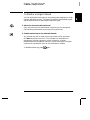
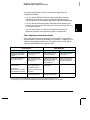
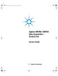
The Agilent Technologies 34970A combines precision measurement
capability with flexible signal connections for your production and
development test systems. Three module slots are built into the rear
of the instrument to accept any combination of data acquisition or
switching modules. The combination of data logging and data
acquisition features makes this instrument a versatile solution for your
testing requirements now and in the future.
Convenient Data Logging Features
• Direct measurement of thermocouples, RTDs, thermistors, dc voltage,
ac voltage, resistance, dc current, ac current, frequency, and period
• Interval scanning with storage of up to 50,000 time-stamped readings
• Independent channel configuration with function, Mx+B scaling,
and alarm limits available on a per-channel basis
• Intuitive user interface with knob for quick channel selection,
menu navigation, and data entry from the front panel
• Portable, ruggedized case with non-skid feet
• BenchLink Data Logger Software for Microsoft ® Windows ® included
Flexible Data Acquisition / Switching Features
• 61⁄2-digit multimeter accuracy, stability, and noise rejection
• Up to 60 channels per instrument (120 single-ended channels)
• Reading rates up to 600 readings per second on a single channel and
scan rates up to 250 channels per second
• Choice of multiplexing, matrix, general-purpose Form C switching,
RF switching, digital I/O, totalize, and 16-bit analog output functions
• GPIB (IEEE-488) interface and RS-232 interface are standard
• SCPI (Standard Commands for Programmable Instruments) compatibility
Agilent 34970A
Data Acquisition / Switch Unit
Page 1 (User’s Guide)
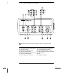
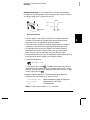
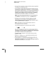
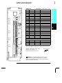
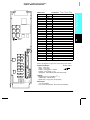
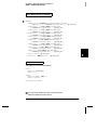
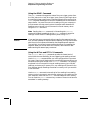
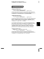
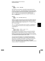
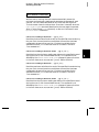
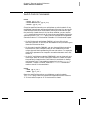
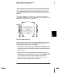
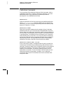
The Front Panel at a Glance
Denotes a menu key. See the next page for details on menu operation.
1 State Storage / Remote Interface Menus
2
3
4
5
6
7
2
Scan Start / Stop Key
Measurement Configuration Menu
Scaling Configuration Menu
Alarm / Alarm Output Configuration Menu
Scan-to-Scan Interval Menu
Scan List Single Step / Read Key
8
9
10
11
12
13
14
Advanced Measurement / Utility Menus
Low-Level Module Control Keys
Single-Channel Monitor On / Off Key
View Scanned Data, Alarms, Errors Menu
Shift / Local Key
Knob
Navigation Arrow Keys
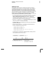
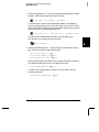
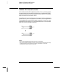
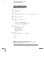
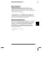
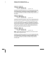
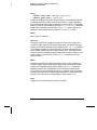
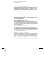
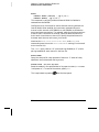
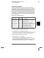
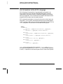
The Front-Panel Menus at a Glance
Several of the front-panel keys guide you through menus to configure
various parameters of the instrument (see previous page). The following
steps demonstrate the menu structure using the
key.
1 Press the menu key. You are automatically
guided to the first level of the menu.
Rotate the knob to view the other choices
on the first level of the menu.
The menu will automatically timeout after
about 20 seconds of inactivity. You will be
returned to the operation in progress prior
to entering the menu.
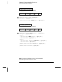
2 Press the same menu key again to move
to the next item of the menu. Typically,
this is where you choose parameter values
for the selected operation.
3 Rotate the knob to view the choices on this
level of the menu. When you reach the end
of the list, rotate the knob in the opposite
direction to view all of the other choices.
The current selection is highlighted for emphasis.
All other choices are dimmed.
4 Press the same menu key again to accept the
change and exit the menu. A brief confirmation
message is displayed.
Tip: To review the current configuration of a specific menu, press the menu key several times.
A message NO CHANGES is displayed when you exit the menu.
3
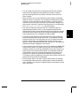
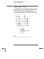
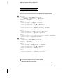
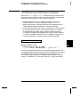
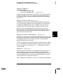
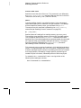
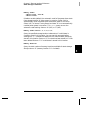
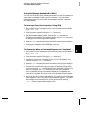
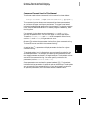
Display Annunciators
SCAN
MON
VIEW
CONFIG
ADRS
RMT
ERROR
EXT
ONCE
MEM
LAST
MIN
MAX
SHIFT
4W
OC
Scan is in progress or enabled. Press and hold
again to turn off.
Monitor mode is enabled. Press
again to turn off.
Scanned readings, alarms, errors, or relay cycles are being viewed.
Channel configuration is in progress on displayed channel.
Measurement is in progress.
Instrument is addressed to listen or talk over the remote interface.
Instrument is in remote mode (remote interface).
Hardware or remote interface errors are detected. Press
to read errors.
Instrument is configured for an external scan interval.
Scan Once mode is enabled. Press
to initiate and hold key to disable.
Reading memory overflow; new readings will overwrite the oldest readings.
Viewed data is the last reading stored during most recent scan.
Viewed data is the minimum reading stored during most recent scan.
Viewed data is the maximum reading stored during most recent scan.
has been pressed. Press
again to turn off.
4-wire function is in use on displayed channel.
Offset compensation is enabled on displayed channel.
Alarms are enabled on displayed channel.
Mx+B scaling is enabled on displayed channel.
HI or LO alarm condition has occurred on indicated alarms.
To review the display annunciators, hold down the
turn on the instrument.
4
key as you
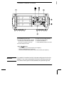
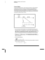
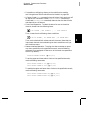
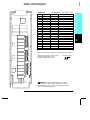
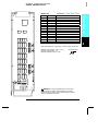
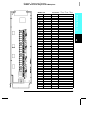
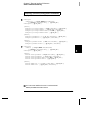
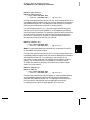
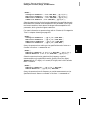
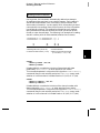
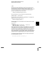
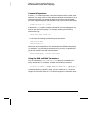
The Rear Panel at a Glance
1 Slot Identifier (100, 200, 300)
2 Ext Trig Input / Alarm Outputs / Channel
Advance Input / Channel Closed Output
(for pinouts, see pages 83 and 128)
3 RS-232 Interface Connector
4
5
6
7
Power-Line Fuse-Holder Assembly
Power-Line Voltage Setting
Chassis Ground Screw
GP-IB (IEEE-488) Interface Connector
Use the
Menu to:
• Select the GP-IB or RS-232 interface (see chapter 2).
• Set the GP-IB address (see chapter 2).
• Set the RS-232 baud rate, parity, and flow control mode (see chapter 2).
WARNING
For protection from electrical shock, the power cord ground must not be
defeated. If only a two-contact electrical outlet is available, connect the
instrument’s chassis ground screw (see above) to a good earth ground.
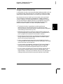
5
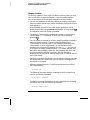
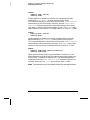
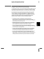
BenchLink Data Logger Software at a Glance
Agilent BenchLink Data Logger is a Windows-based application
designed to make it easy to use the 34970A with your PC for gathering
and analyzing measurements. Use the software to set up your test,
acquire and archive measurement data, and perform real-time display
and analysis of your incoming measurements.
BenchLink Data Logger’s key functions include the following:
• Configure measurements on the spreadsheet-like Scan Setup page.
• Display measurements graphically using the real-time Data Grid,
Strip Chart, Readout, Bar Meter, XY Plot, and Histogram windows.
• Add or configure graphics at any time.
• Use graphical controls to set output voltages, close channels, output
digital values, or view alarms.
• Copy measurement data and graphics to a file or to the Clipboard for
use in other applications.
• Add textual annotation and explanations to measurement results and
test reports.
• Track readings on a single channel through the Monitor toolbar.
• Enter information into the Event Log automatically or manually
while acquiring measurement data or during post-scan analysis.
• Print scan setups, event logs, and graphics.
• Communicate with the instrument using GPIB, RS-232, modem,
or LAN (using a LAN-to-GPIB gateway).
To install the software, refer to “Installing BenchLink Data Logger
Software” on page 18.
To learn more about the software and its capabilities, refer to the
On-Line Help System for BenchLink Data Logger.
6
The Plug-In Modules at a Glance
For complete specifications on each plug-in module, refer to the module
sections in chapter 9.
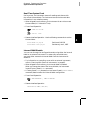
34901A 20-Channel Armature Multiplexer
• 20 channels of 300 V switching
• Two channels for DC or AC current measurements (100 nA to 1A)
• Built-in thermocouple reference junction
• Switching speed of up to 60 channels per second
• Connects to the internal multimeter
• For detailed information and a module diagram, see page 164.
Each of the 20 channels switches both HI and LO inputs, thus providing
fully isolated inputs to the internal multimeter. The module is divided
into two banks of 10 two-wire channels each. When making four-wire
resistance measurements, channels from Bank A are automatically
paired with channels from Bank B. Two additional fused channels are
included on the module (22 channels total) for making calibrated DC or
AC current measurements with the internal multimeter (external shunt
resistors are not required). You can close multiple channels on this
module only if you have not configured any channels to be part of the
scan list. Otherwise, all channels on the module are break-before-make.
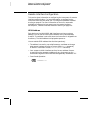
34902A 16-Channel Reed Multiplexer
• 16 channels of 300 V switching
• Built-in thermocouple reference junction
• Switching speed of up to 250 channels per second
• Connects to the internal multimeter
• For detailed information and a module diagram, see page 166.
Use this module for high-speed scanning and high-throughput
automated test applications. Each of the 16 channels switches both
HI and LO inputs, thus providing fully isolated inputs to the internal
multimeter. The module is divided into two banks of eight two-wire
channels each. When making four-wire resistance measurements,
channels from Bank A are automatically paired with channels from
Bank B. You can close multiple channels on this module only if you have
not configured any channels to be part of the scan list. Otherwise, all
channels on the module are break-before-make.
7
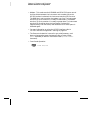
34903A 20-Channel Actuator / General-Purpose Switch
• 300 V, 1 A actuation and switching
• SPDT (Form C) latching relays
• Breadboard area for custom circuits
• For detailed information and a module diagram, see page 168.
Use this module for those applications that require high-integrity
contacts or quality connections of non-multiplexed signals. This module
can switch 300 V, 1 A (50 W maximum switch power) to your device
under test or to actuate external devices. Screw terminals on the module
provide access to the Normally-Open, Normally-Closed, and Common
contacts for each of the 20 switches. A breadboard area is provided near
the screw terminals to implement custom circuitry, such as simple
filters, snubbers, or voltage dividers.
34904A 4x8 Two-Wire Matrix Switch
• 32 two-wire crosspoints
• Any combination of inputs and outputs can be connected at a time
• 300 V, 1 A switching
• For detailed information and a module diagram, see page 170.
Use this module to connect multiple instruments to multiple points on
your device under test at the same time. You can connect rows and
columns between multiple modules to build larger matrices such as
8x8 and 4x16, with up to 96 crosspoints in a single mainframe.
34905/6A Dual 4-Channel RF Multiplexers
• 34905A (50Ω) / 34906A (75Ω)
• 2 GHz bandwidth with on-board SMB connections
• 1 GHz bandwidth with SMB-to-BNC adapter cables provided
• For detailed information and a module diagram, see page 172.
These modules offer wideband switching capabilities for high frequency
and pulsed signals. Each module is organized in two independent banks
of 4-to-1 multiplexers. Both modules offer low crosstalk and excellent
insertion loss performance. To create larger RF multiplexers, you can
cascade multiple banks together. Only one channel in each bank may be
closed at a time.
8
34907A Multifunction Module
• Two 8-bit Digital Input/Output ports, 400 mA sink, 42 V open collector
• 100 kHz Totalize input with 1 Vpp sensitivity
• Two ±12 V Calibrated Analog Outputs
• For detailed information and module block diagrams, see page 174.
Use this module to sense status and control external devices such as
solenoids, power relays, and microwave switches. For greater flexibility,
you can read digital inputs and the count on the totalizer during a scan.
34908A 40-Channel Single-Ended Multiplexer
• 40 channels of 300 V single-ended (common LO) switching
• Built-in thermocouple reference junction
• Switching speed of up to 60 channels per second
• Connects to the internal multimeter
• For detailed information and a module diagram, see page 176.
Use this module for high-density switching applications which require
single-wire inputs with a common LO. All relays are break-before-make
to ensure that only one relay is connected at any time.
9
In This Book
Quick Start Chapter 1 helps you get familiar with a few of the
instrument’s front-panel features. This chapter also shows how to
install the BenchLink Data Logger software.
Front-Panel Overview Chapter 2 introduces you to the front-panel
menus and describes some of the instrument’s menu features.
System Overview Chapter 3 gives an overview of a data acquisition
system and describes how parts of a system work together.
Features and Functions Chapter 4 gives a detailed description of the
instrument’s capabilities and operation. You will find this chapter
useful whether you are operating the instrument from the front panel or
over the remote interface.
Remote Interface Reference Chapter 5 contains reference
information to help you program the instrument over the remote
interface using the SCPI language.
Error Messages Chapter 6 lists the error messages that may appear
as you are working with the instrument. Each listing contains enough
information to help you diagnose and solve the problem.
Application Programs Chapter 7 contains several remote interface
program examples to help you develop programs for your application.
Tutorial Chapter 8 discusses measurement considerations and
techniques to help you obtain the best accuracies and reduce sources of
measurement noise.
Specifications Chapter 9 lists the technical specifications for the
mainframe and plug-in modules.
If you have questions relating to the operation of the 34970A,
call 1-800-452-4844 in the United States, or contact your nearest
Agilent Technologies Sales Office.
If your 34970A fails within three years of original purchase, Agilent will
either repair or replace it free of charge. Call 1-877-447-7278 and ask
for “Express Exchange” or contact your local Agilent office.
10
Contents
Chapter 1 Quick Start
To Prepare the Instrument for Use 17
Installing BenchLink Data Logger Software 18
To Connect Wiring to a Module 20
To Set the Time and Date 22
To Configure a Channel for Scanning 23
To Copy a Channel Configuration 25
To Close a Channel 26
If the Instrument Does Not Turn On 27
To Adjust the Carrying Handle 29
To Rack Mount the Instrument 30
Chapter 2 Front-Panel Overview
Contents
Front-Panel Menu Reference 35
To Monitor a Single Channel 37
To Set a Scan Interval 38
To Apply Mx+B Scaling to Measurements 39
To Configure Alarm Limits 40
To Read a Digital Input Port 42
To Write to a Digital Output Port 43
To Read the Totalizer Count 44
To Output a DC Voltage 45
To Configure the Remote Interface 46
To Store the Instrument State 48
Chapter 3 System Overview
Data Acquisition System Overview 50
Signal Routing and Switching 57
Measurement Input 60
Control Output 67
11
Contents
Contents
Chapter 4 Features and Functions
SCPI Language Conventions 73
Scanning 74
Single-Channel Monitoring 93
Scanning With External Instruments 95
General Measurement Configuration 98
Temperature Measurement Configuration 106
Voltage Measurement Configuration 113
Resistance Measurement Configuration 115
Current Measurement Configuration 116
Frequency Measurement Configuration 118
Mx+B Scaling 119
Alarm Limits 122
Digital Input Operations 133
Totalizer Operations 135
Digital Output Operations 138
DAC Output Operations 139
System-Related Operations 140
Remote Interface Configuration 150
Calibration Overview 155
Factory Reset State 160
Instrument Preset State 161
Multiplexer Module Default Settings 162
Module Overview 163
34901A 20-Channel Multiplexer 164
34902A 16-Channel Multiplexer 166
34903A 20-Channel Actuator 168
34904A 4x8 Matrix Switch 170
34905A/6A Dual 4-Channel RF Multiplexers 172
34907A Multifunction Module 174
34908A 40-Channel Single-Ended Multiplexer 176
12
Contents
Chapter 5 Remote Interface Reference
Contents
SCPI Command Summary 181
Simplified Programming Overview 201
The MEASure? and CONFigure Commands 207
Setting the Function, Range, and Resolution 214
Temperature Configuration Commands 219
Voltage Configuration Commands 223
Resistance Configuration Commands 224
Current Configuration Commands 224
Frequency Configuration Commands 225
Scanning Overview 226
Single-Channel Monitoring Overview 237
Scanning With an External Instrument 239
Mx+B Scaling Overview 244
Alarm System Overview 247
Digital Input Commands 255
Totalizer Commands 256
Digital Output Commands 258
DAC Output Commands 258
Switch Control Commands 259
State Storage Commands 261
System-Related Commands 264
Interface Configuration Commands 269
RS-232 Interface Configuration 270
Modem Communications 274
The SCPI Status System 275
Status System Commands 286
Calibration Commands 292
Service-Related Commands 294
An Introduction to the SCPI Language 296
Using Device Clear 302
Chapter 6 Error Messages
Execution Errors 305
Instrument Errors 309
Self-Test Errors 314
Calibration Errors 315
Plug-In Module Errors 317
13
Contents
Chapter 7 Application Programs
Example Programs for Excel 7.0 321
Example Programs for C and C++ 328
Chapter 8 Tutorial
Contents
System Cabling and Connections 335
Measurement Fundamentals 343
Low-Level Signal Multiplexing 378
Actuators and General-Purpose Switching 384
Matrix Switching 388
RF Signal Multiplexing 390
Multifunction Module 392
Relay Life and Preventative Maintenance 399
Chapter 9 Specifications
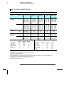
DC, Resistance, and Temperature Accuracy Specifications 404
DC Measurement and Operating Characteristics 405
AC Accuracy Specifications 406
AC Measurement and Operating Characteristics 407
Measurement Rates and System Characteristics 408
Module Specifications 409
BenchLink Data Logger Software Specifications 412
Product and Module Dimensions 413
To Calculate Total Measurement Error 414
Interpreting Internal DMM Specifications 416
Configuring for Highest Accuracy Measurements 419
Index
14
1
1
Quick Start
Quick Start
One of the first things you will want to do with your instrument is to
become acquainted with the front panel. We have written the exercises
in this chapter to prepare the instrument for use and help you get
familiar with some of its front-panel operations.
The front panel has several groups of keys to select various functions
and operations. A few keys have a shifted function printed in blue below
the key. To perform a shifted function, press
(the SHIFT annunciator
will turn on). Then, press the key that has the desired label below it.
For example, to select the Utility Menu, press
.
If you accidentally press
annunciator.
, just press it again to turn off the SHIFT
This chapter is divided into the following sections:
• To Prepare the Instrument for Use, on page 17
• Installing BenchLink Data Logger Software, on page 18
• To Connect Wiring to a Module, on page 20
• To Set the Time and Date, on page 22
• To Configure a Channel for Scanning, on page 23
• To Copy a Channel Configuration, on page 25
• To Close a Channel, on page 26
• If the Instrument Does Not Turn On, on page 27
• To Adjust the Carrying Handle, on page 29
• To Rack Mount the Instrument, on page 30
16
Chapter 1 Quick Start
To Prepare the Instrument for Use
1
To Prepare the Instrument for Use
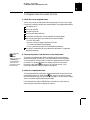
1 Check the list of supplied items.
Verify that you have received the following items with your instrument.
If anything is missing, contact your nearest Agilent Technologies Sales Office.
One power cord.
This User’s Guide.
One Service Guide.
One Quick Reference Guide.
Certificate of Calibration (if you ordered the internal DMM).
Quick Start Package (if you ordered the internal DMM):
• One RS-232 cable.
• BenchLink Data Logger Software CD-ROM.
To install the software, see page 18.
• One J-type thermocouple and a flatblade screwdriver.
Any plug-in modules that you ordered are delivered in a separate
shipping container.
On/Standby
Switch
WARNING
Note that this switch
is Standby only.
To disconnect the
mains from the
instrument, remove
the power cord.
2 Connect the power cord and turn on the instrument.
The front-panel display will light up briefly while the instrument
performs its power-on self-test. The GPIB address is also displayed.
The instrument initially powers up with all measurement channels
turned off. To review the power-on display with all annunciators
turned on, hold down
as you turn on the instrument. If the
instrument does not turn on properly, see page 27.
3 Perform a complete self-test.
The complete self-test performs a more extensive set of tests than those
performed at power-on. Hold down
as you turn on the instrument
and hold down the key until you hear a long beep. The self-test will begin
when you release the key following the beep.
If the self-test fails, see the 34970A Service Guide for instructions on
returning the instrument to Agilent for service.
17
Chapter 1 Quick Start
Installing BenchLink Data Logger Software
Installing BenchLink Data Logger Software
If you ordered the 34970A with the internal DMM, then the BenchLink
Data Logger software is included. The software is shipped on one
CD-ROM, but includes a utility to build installation floppy disks.
To install the software on your PC, you will need a minimum of 12 MB
of free disk space.
For system requirements and additional details on the features of the
software, refer to the specifications in chapter 9.
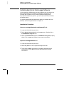
Installation Procedure
If you are running Windows 95 or Windows NT 4.0 ®
1. Insert the CD-ROM into your drive.
2. Select Settings | Control Panel from the Start menu. Double-click on
the Add/Remove Programs icon.
3. Select the Install/Uninstall tab on the Add/Remove Programs property
sheet. Click on Install and follow the on-screen instructions.
If you are running Windows ® 3.1
1. Insert the CD-ROM into your drive.
2. Select File | Run from the Program Manager menu bar.
3. Type <drive>:\setup, where drive is the letter representing your
CD-ROM drive. Click OK to continue and follow the on-screen
instructions.
18
Chapter 1 Quick Start
Installing BenchLink Data Logger Software
1
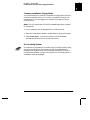
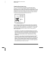
Creating Installation Floppy Disks
You have the option to create an installation on floppy disks from the
CD-ROM installation utility. This utility is provided so that you can
install BenchLink Data Logger on a computer that does not have a
CD-ROM drive.
Note: You will need a total of five (5) formatted floppy disks to create
an installation.
1. Go to a computer that is equipped with a CD-ROM drive.
2. Start the installation procedure as described on the previous page.
3. Select Create disks... on the initial display of the installation
procedures and follow the on-screen instructions.
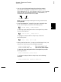
On-Line Help System
The software is shipped with an extensive on-line Help system to help
you learn the features of the software as well as troubleshoot any
problems that might arise as you are using the software. As you are
installing the software, you will notice that the on-line Help system is
available in several languages.
19
Chapter 1 Quick Start
To Connect Wiring to a Module
To Connect Wiring to a Module
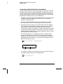
1 Remove the module cover.
2 Connect wiring to the screw terminals.
20 AWG Typical
6 mm
3 Route wiring through strain relief.
4 Replace the module cover.
Cable Tie Wrap
(optional)
5 Install the module into mainframe.
Channel Number:
Slot Channel
20
Wiring Hints...
• For detailed information on each module,
refer to the section starting on page 163.
• To reduce wear on the internal DMM relays,
wire like functions on adjacent channels.
• For information on grounding and shielding,
see page 335.
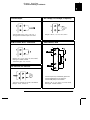
• The diagrams on the next page show how to
connect wiring to a multiplexer module for
each measurement function.
Chapter 1 Quick Start
To Connect Wiring to a Module
1
Thermocouple
Thermocouple Types: B, E, J, K, N, R, S, T
See page 351 for thermocouple color codes.
2-Wire Ohms / RTD / Thermistor
DC Voltage / AC Voltage / Frequency
Ranges: 100 mV, 1 V, 10 V, 100 V, 300 V
4-Wire Ohms / RTD
Ranges: 100, 1 k, 10 k, 100 k, 1 M, 10 M, 100 MΩ
RTD Types: 0.00385, 0.00391
Thermistor Types: 2.2 k, 5 k, 10 k
DC Current / AC Current
Channel n (source) is automatically paired with
Channel n+10 (sense) on the 34901A or
Channel n+8 (sense) on the 34902A.
Valid only on channels 21 and 22 on the 34901A.
Ranges: 10 mA, 100 mA, 1A
Ranges: 100, 1 k, 10 k, 100 k, 1 M, 10 M, 100 MΩ
RTD Types: 0.00385, 0.00391
21
Chapter 1 Quick Start
To Set the Time and Date
To Set the Time and Date
All readings during a scan are automatically time stamped and stored
in non-volatile memory. In addition, alarm data is time stamped and
stored in a separate non-volatile memory queue.
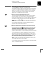
1 Set the time of day.
Utility
Use
and
to select the field to modify and turn the knob to change
the value. You can also edit the AM/PM field.
7,0(30
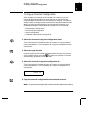
2 Set the date.
Utility
Use
and
the value.
to select the field to modify and turn the knob to change
-81
22
Chapter 1 Quick Start
To Configure a Channel for Scanning
1
To Configure a Channel for Scanning
Any channel that can be “read” by the instrument can also be included
in a scan. This includes readings on multiplexer channels, a read of a
digital port, or a read of the count on a totalizer channel. Automated
scanning is not allowed with the RF multiplexer, matrix, actuator,
digital output, or voltage output (DAC) modules.
1 Select the channel to be added to the scan list.
Turn the knob until the desired channel is shown on the right side of
front-panel display. The channel number is a three-digit number;
the left-most digit represents the slot number (100, 200, or 300) and the
two digits on the right indicate the channel number (102, 110, etc.).
Note: You can use
or next slot.
and
to skip to the beginning of the previous
For this example, assume that you have the 34901A multiplexer
installed in slot 100 and select channel 103.
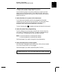
2 Select the measurement parameters for the selected channel.
Use the knob to scroll through the measurement choices on each level
of the menu. When you press
to make your selection, the menu
automatically guides you through all relevant choices to configure a
measurement on the selected function. When you have finished
configuring the parameters, you are automatically exited from the menu.
The current selection (or default) is displayed in full bright for easy
identification. When you make a different selection, the new choice is
shown in full bright and it becomes the default selection. The order of
the choices always remains the same; however, you always enter the
menu at the current (full bright) setting for each parameter.
Note: The menu will timeout after about 20 seconds of inactivity and
any changes made previously will take effect.
For this example, configure channel 103 to measure a J-type thermocouple
with 0.1 °C of display resolution.
23
Chapter 1 Quick Start
To Configure a Channel for Scanning
Note: Press
to sequentially step through the scan list and take a
measurement on each channel (readings are not stored in memory).
This is an easy way to verify your wiring connections before initiating
the scan.
3 Run the scan and store the readings in non-volatile memory.
The instrument automatically scans the configured channels in
consecutive order from slot 100 through slot 300 (the SCAN annunciator
turns on). Channels that are not configured are skipped during the scan.
In the default configuration, the instrument continuously scans the
configured channels at a 10-second interval.
Press and hold
to stop the scan.
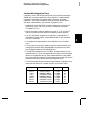
4 View the data from the scan.
All readings taken during a scan are automatically time stamped and
stored in non-volatile memory. During the scan, the instrument
calculates and stores the minimum, maximum, and average on all
channels in the scan list. You can read the contents of memory at any
time, even during a scan.
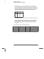
From the front panel, data is available for the last 100 readings on each
channel readings taken during a scan (all of the data is available from
the remote interface). From the View menu, select READINGS and press
again. Then press
and
to choose the data you want to view
for the selected channel as shown in the table below.
and
Select Channel
Last Reading on Channel
Time of Last Reading
Minimum Reading on Channel
Time of Minimum Reading
Maximum Reading on Channel
Time of Maximum Reading
Average of Readings on Channel
Second Most Recent Reading on Channel
Third Most Recent Reading on Channel
99th Most Recent Reading on Channel
24
Chapter 1 Quick Start
To Copy a Channel Configuration
1
To Copy a Channel Configuration
After configuring a channel to be included in the scan list, you can
copy that same configuration to other channels in the instrument
(including digital channels on the multifunction module). This feature
makes it easy to configure several channels for the same measurement.
When you copy the configuration from one channel to another, the
following parameters are automatically copied to the new channel:
• Measurement configuration
• Mx+B scaling configuration
• Alarm configuration
• Advanced measurement configuration
1 Select the channel to copy the configuration from.
Turn the knob until the desired channel is shown on the right side of
front-panel display. For this example, let’s copy the configuration from
channel 103.
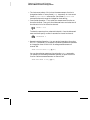
2 Select the copy function.
Use the knob to scroll through the measurement choices until you see
COPY CONFIG. When you press
to make your selection, the menu
automatically guides you to the next step.
3 Select the channel to copy the configuration to.
Turn the knob until the desired channel is shown on the right side of
front-panel display. For this example, let’s copy the configuration to
channel 105.
3$67(72
4 Copy the channel configuration to the selected channel.
Note: To copy the same configuration to other channels, repeat this procedure.
25
Chapter 1 Quick Start
To Close a Channel
To Close a Channel
On the multiplexer and switch modules, you can close and open individual
relays on the module. However, note that if you have already configured
any multiplexer channels for scanning, you cannot independently close
and open individual relays on that module.
1 Select the channel.
Turn the knob until the desired channel is shown on the right side of
front-panel display. For this example, select channel 213.
2 Close the selected channel.
3 Open the selected channel.
Note:
will sequentially open all channels on the module in the
selected slot.
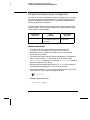
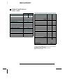
The table below shows the low-level control operations available for
each of the plug-in modules.
Plug-In Module
,
34901A 20-Channel Mux
•
•
•
•
34902A 16-Channel Mux
•
•
•
•
34908A 40-Channel Single-Ended Mux [1]
•
•
•
•
34903A 20-Channel Actuator
•
•
34904A 4x8 Matrix
•
•
[2]
•
34906A Dual 4-Channel RF Mux (75Ω) [2]
•
34905A Dual 4-Channel RF Mux (50Ω)
34907A Multifunction Module (DIO)
•
34907A Multifunction Module (Totalizer)
•
34907A Multifunction Module (DAC)
•
•
•
[1] Only one channel can be closed at a time on this module.
[2] Only one channel in each bank can be closed at a time on this module.
26
•
Chapter 1 Quick Start
If the Instrument Does Not Turn On
1
If the Instrument Does Not Turn On
Use the following steps to help solve problems you might encounter
when turning on the instrument. If you need more help, refer to the
34970A Service Guide for instructions on returning the instrument to
Agilent for service.
1 Verify that there is ac power to the instrument.
First, verify that the power cord is firmly plugged into the power
receptacle on the rear panel of the instrument. You should also make
sure that the power source you plugged the instrument into is
energized. Then, verify that the instrument is turned on.
The On/Standby switch
is located on the lower left side of the front panel.
2 Verify the power-line voltage setting.
The line voltage is set to the proper value for your country when the
instrument is shipped from the factory. Change the voltage setting if
it is not correct. The settings are: 100, 120, 220, or 240 Vac.
Note: For 127 Vac operation, use the 120 Vac setting.
For 230 Vac operation, use the 220 Vac setting.
See the next page if you need to change the line voltage setting.
3 Verify that the power-line fuse is good.
The instrument is shipped from the factory with a 500 mA fuse installed.
This is the correct fuse for all line voltages.
See the next page if you need to replace the power-line fuse.
To replace the 500 mAT, 250 V fuse, order Agilent part number 2110-0458.
27
Chapter 1 Quick Start
If the Instrument Does Not Turn On
1 Remove the power cord. Remove the
fuse-holder assembly from the rear panel.
2 Remove the line-voltage selector from
the assembly.
Fuse: 500 mAT (for all line voltages)
Agilent Part Number: 2110-0458
3 Rotate the line-voltage selector until the
correct voltage appears in the window.
4 Replace the fuse-holder assembly in
the rear panel.
100, 120 (127), 220 (230) or 240 Vac
Verify that the correct line voltage is selected and the power-line fuse is good.
28
Chapter 1 Quick Start
To Adjust the Carrying Handle
1
To Adjust the Carrying Handle
To adjust the position, grasp the handle by the sides and pull outward.
Then, rotate the handle to the desired position.
Bench-top viewing positions
Carrying position
29
Chapter 1 Quick Start
To Rack Mount the Instrument
To Rack Mount the Instrument
You can mount the instrument in a standard 19-inch rack cabinet using
one of three optional kits available. Instructions and mounting
hardware are included with each rack-mounting kit. Any Agilent System II
instrument of the same size can be rack-mounted beside the 34970A.
Note: Remove the carrying handle, and the front and rear rubber bumpers,
before rack-mounting the instrument.
To remove the handle, rotate it to the vertical position and pull the ends outward.
Front
Rear (bottom view)
To remove the rubber bumper, stretch a corner and then slide it off.
30
Chapter 1 Quick Start
To Rack Mount the Instrument
1
To rack mount a single instrument, order adapter kit 5063-9240.
To rack mount two instruments side-by-side, order lock-link kit 5061-9694 and
flange kit 5063-9212. Be sure to use the support rails inside the rack cabinet.
To install one or two instruments in a sliding support shelf, order shelf 5063-9255,
and slide kit 1494-0015 (for a single instrument, also order filler panel 5002-3999).
31
32
2
2
Front-Panel
Overview
Front-Panel Overview
This chapter introduces you to the front-panel keys and menu operation.
This chapter does not give a detailed description of every front-panel
key or menu operation. It does, however, give you a good overview of the
front-panel menu and many front-panel operations. See chapter 4
“Features and Functions,” starting on page 71, for a complete discussion
of the instrument’s capabilities and operation.
This chapter is divided into the following sections:
• Front-Panel Menu Reference, on page 35
• To Monitor a Single Channel, on page 37
• To Set a Scan Interval, on page 38
• To Apply Mx+B Scaling to Measurements, on page 39
• To Configure Alarm Limits, on page 40
• To Read a Digital Input Port, on page 42
• To Write to a Digital Output Port, on page 43
• To Read the Totalizer Count, on page 44
• To Output a DC Voltage, on page 45
• To Configure the Remote Interface, on page 46
• To Store the Instrument State, on page 48
34
Chapter 2 Front-Panel Overview
Front-Panel Menu Reference
Front-Panel Menu Reference
This section gives an overview of the front-panel menus. The menus are
designed to automatically guide you through all parameters required to
configure a particular function or operation. The remainder of this
chapter shows examples of using the front-panel menus.
Configure the measurement parameters on the displayed channel.
•
•
•
•
•
•
Select measurement function (dc volts, ohms, etc.) on the displayed channel.
Select transducer type for temperature measurements.
Select units (°C, °F, or K) for temperature measurements.
Select measurement range or autorange.
Select measurement resolution.
Copy and paste measurement configuration to other channels.
Configure the scaling parameters for the displayed channel.
• Set the gain (“M”) and offset (“B”) value for the displayed channel.
• Make a null measurement and store it as the offset value.
• Specify a custom label (RPM, PSI, etc.) for the displayed channel.
Configure alarms on the displayed channel.
• Select one of four alarms to report alarm conditions on the displayed channel.
• Configure a high limit, low limit, or both for the displayed channel.
• Configure a bit pattern which will generate an alarm (digital input only).
Configure the four Alarm Output hardware lines.
• Clear the state of the four alarm output lines.
• Select the “Latch” or “Track” mode for the four alarm output lines.
• Select the slope (rising or falling edge) for the four alarm output lines.
Configure the event or action that controls the scan interval.
• Select the scan interval mode (interval, manual, external, or alarm).
• Select the scan count.
35
2
Chapter 2 Front-Panel Overview
Front-Panel Menu Reference
Configure the advanced measurement features on displayed channel.
•
•
•
•
•
•
•
•
•
Set the integration time for measurements on the displayed channel.
Set the channel-to-channel delay for scanning.
Enable/disable the thermocouple check feature (T/C measurements only).
Select the reference junction source (T/C measurements only).
Set the low frequency limit (ac measurements only).
Enable/disable offset compensation (resistance measurements only).
Select the binary or decimal mode for digital operations (digital input/output only).
Configure the totalizer reset mode (totalizer only).
Select which edge is detected (rising or falling) for totalizer operations.
Configure system-related instrument parameters.
•
•
•
•
•
Set the real-time system clock and calendar.
Query the firmware revisions for the mainframe and installed modules.
Select the instrument’s power-on configuration (last or factory reset).
Enable/disable the internal DMM.
Secure/unsecure the instrument for calibration.
View readings, alarms, and errors.
•
•
•
•
View the last 100 scanned readings from memory (last, min, max, and average).
View the first 20 alarms in the alarm queue (reading and time alarm occurred).
View up to 10 errors in the error queue.
Read the number of cycles for the displayed relay (relay maintenance feature).
Store and recall instrument states.
• Store up to five instrument states in non-volatile memory.
• Assign a name to each storage location.
• Recall stored states, power-down state, factory reset state, or preset state.
Configure the remote interface.
• Select the GPIB address.
• Configure the RS-232 interface (baud rate, parity, and flow control).
36
Chapter 2 Front-Panel Overview
To Monitor a Single Channel
To Monitor a Single Channel
You can use the Monitor function to continuously take readings on a single
channel, even during a scan. This feature is useful for troubleshooting your
system before a test or for watching an important signal.
1 Select the channel to be monitored.
Only one channel can be monitored at a time but you can change the
channel being monitored at any time by turning the knob.
2 Enable monitoring on the selected channel.
Any channel that can be “read” by the instrument can be monitored
(the MON annunciator turns on). This includes any combination of
temperature, voltage, resistance, current, frequency, or period
measurements on multiplexer channels. You can also monitor a digital
input port or the totalizer count on the multifunction module.
To disable monitoring, press
again.
37
2
Chapter 2 Front-Panel Overview
To Set a Scan Interval
To Set a Scan Interval
You can set the instrument’s internal timer to automatically scan at a
specific interval (e.g., start a new scan sweep every 10 seconds) or when
an external TTL trigger pulse is received. You can configure the
instrument to scan continuously or to stop after sweeping through the
scan list a specified number of times.
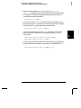
1 Select the interval scan mode.
For this example, select the Interval Scan mode which allows you to set
the time from the start of one scan sweep to the start of the next scan
sweep. Set the interval to any value between 0 and 99 hours.
,17(59$/6&$1
2 Select the scan count.
You can specify the number of times that the instrument will sweep
through the scan list (the default is continuous). When the specified
number of sweeps have occurred, the scan stops. Set the scan count to
any number between 1 and 50,000 scans (or continuous).
6&$16
3 Run the scan and store the readings in memory.
38
Chapter 2 Front-Panel Overview
To Apply Mx+B Scaling to Measurements
To Apply Mx+B Scaling to Measurements
The scaling function allows you to apply a gain and offset to all readings
on a specified multiplexer channel during a scan. In addition to setting
the gain (“M”) and offset (“B”) values, you can also specify a custom
measurement label for your scaled readings (RPM, PSI, etc.).
1 Configure the channel.
You must configure the channel (function, transducer type, etc.) before
applying any scaling values. If you change the measurement
configuration, scaling is turned off on that channel and the gain and
offset values are reset (M=1 and B=0).
2 Set the gain and offset values.
The scaling values are stored in non-volatile memory for the specified
channels. A Factory Reset turns off scaling and clears the scaling values
on all channels. An Instrument Preset or Card Reset does not clear the
scaling values and does not turn off scaling.
, Set Gain
,9'& Set Offset
3 Select the custom label.
You can specify an optional three-character label for your scaled
readings (RPM, PSI, etc.). The default label is the standard engineering
unit for the selected function (VDC, OHM, etc.).
/$%(/$6/%6
4 Run the scan and store the scaled readings in memory.
39
2
Chapter 2 Front-Panel Overview
To Configure Alarm Limits
To Configure Alarm Limits
The instrument has four alarms which you can configure to alert you
when a reading exceeds specified limits on a channel during a scan.
You can assign a high limit, a low limit, or both to any configured
channel in the scan list. You can assign multiple channels to any of the
four available alarms (numbered 1 through 4).
1 Configure the channel.
You must configure the channel (function, transducer type, etc.) before
setting any alarm limits. If you change the measurement configuration,
alarms are turned off and the limit values are cleared. If you plan to use
Mx+B scaling on a channel which will also use alarms, be sure to
configure the scaling values first.
2 Select which of the four alarms you want to use.
86($/$50
3 Select the alarm mode on the selected channel.
You can configure the instrument to generate an alarm when a
measurement exceeds the specified HI or LO limits (or both) on a
measurement channel.
+,$/$5021/<
40
Chapter 2 Front-Panel Overview
To Configure Alarm Limits
4 Set the limit value.
The alarm limit values are stored in non-volatile memory for the
specified channels. The default values for the high and low limits are “0”.
The low limit must always be less than or equal to the high limit, even if
you are using only one of the limits. A Factory Reset clears all alarm
limits and turns off all alarms. An Instrument Preset or Card Reset does
not clear the alarm limits and does not turn off alarms.
,°&
5 Run the scan and store the readings in memory.
If an alarm occurs on a channel as it is being scanned, then that
channel’s alarm status is stored in reading memory as the readings are
taken. Each time you start a new scan, the instrument clears all
readings (including alarm data) stored in reading memory from the
previous scan. As alarms are generated, they are also logged in an
alarm queue, which is separate from reading memory. Up to 20 alarms
can be logged in the alarm queue. Reading the alarm queue using the
View menu clears the alarms in the queue.
41
2
Chapter 2 Front-Panel Overview
To Read a Digital Input Port
To Read a Digital Input Port
The multifunction module (34907A) has two non-isolated 8-bit
input/output ports which you can use for reading digital patterns.
You can read the live status of the bits on the port or you can configure
a scan to include a digital read.
1 Select the Digital Input port.
Select the slot containing the multifunction module and continue
turning the knob until DIN is displayed (channel 01 or 02).
2 Read the specified port.
You can specify whether you want to use binary or decimal format.
Once you have selected the number base, it is used for all input or
output operations on the same port. To change the number base,
press the
key and select USE BINARY or USE DECIMAL.
' , 1 Binary Display Shown
Bit 7
Bit 0
The bit pattern read from the port will be displayed until you press
another key, turn the knob, or until the display times out.
Note: To add a digital input channel to a scan list, press
the DIO READ choice.
42
and select
Chapter 2 Front-Panel Overview
To Write to a Digital Output Port
To Write to a Digital Output Port
The multifunction module (34907A) has two non-isolated 8-bit
input/output ports which you can use for outputting digital patterns.
2
1 Select the Digital Output port.
Select the slot containing the multifunction module and continue
turning the knob until DIN is displayed (channel 01 or 02).
2 Enter the bit pattern editor.
Notice that the port is now converted to an output port (DOUT).
' 2 8 7 Binary Display Shown
Bit 7
Bit 0
3 Edit the bit pattern.
Use the knob and
or
keys to edit the individual bit values.
You can specify whether you want to use binary or decimal format.
Once you have selected the number base, it is used for all input or
output operations on the same port. To change the number base,
press the
key and select USE BINARY or USE DECIMAL.
'287
Decimal Display Shown
4 Output the bit pattern to the specified port.
The specified bit pattern is latched on the specified port. To cancel an
output operation in progress, wait for the display to time out.
43
Chapter 2 Front-Panel Overview
To Read the Totalizer Count
To Read the Totalizer Count
The multifunction module (34907A) has a 26-bit totalizer which can
count pulses at a 100 kHz rate. You can manually read the totalizer
count or you can configure a scan to read the count.
1 Select the totalizer channel.
Select the slot containing the multifunction module and continue
turning the knob until TOTALIZE is displayed (channel 03).
2 Configure the totalize mode.
The internal count starts as soon as you turn on the instrument.
You can configure the totalizer to reset the count to “0” after being read
or it can count continuously and be manually reset.
5($'5(6(7
3 Read the count.
The count is read once each time you press
; the count does not
update automatically on the display. As configured in this example,
the count is automatically reset to “0” each time you read it.
727
The count will be displayed until you press another key, turn the knob,
or until the display times out. To manually reset the totalizer count,
press
.
Note: To add a totalizer channel to a scan list, press
TOT READ choice.
44
and select the
Chapter 2 Front-Panel Overview
To Output a DC Voltage
To Output a DC Voltage
The multifunction module (34907A) has two analog outputs capable of
outputting calibrated voltages between ±12 volts.
2
1 Select a DAC Output channel.
Select the slot containing the multifunction module and continue
turning the knob until DAC is displayed (channel 04 or 05).
2 Enter the output voltage editor.
9'$&
3 Set the desired output voltage.
Use the knob and
or
keys to edit the individual digits.
9 ' $ &
4 Output the voltage from the selected DAC.
The output voltage will be displayed until you press another key or turn
the knob. To manually reset the output voltage to 0 volts, press
.
45
Chapter 2 Front-Panel Overview
To Configure the Remote Interface
To Configure the Remote Interface
The instrument is shipped with both an GPIB (IEEE-488) interface
and an RS-232 interface. Only one interface can be enabled at a time.
The GPIB interface is selected when the instrument is shipped from
the factory.
GPIB Configuration
1 Select the GPIB (HPIB) interface.
+3,%
2 Select the GPIB address.
Interface
You can set the instrument’s address to any value between 0 and 30.
The factory setting is address “9”.
$''5(66
3 Save the change and exit the menu.
Interface
Note: Your computer’s GPIB interface card has its own address.
Be sure to avoid using the computer’s address for any instrument on the
interface bus. Agilent’s GPIB interface cards generally use address “21”.
46
Chapter 2 Front-Panel Overview
To Configure the Remote Interface
RS-232 Configuration
1 Select the RS-232 interface.
2
56
2 Select the baud rate.
Interface
Select one of the following: 1200, 2400, 4800, 9600, 19200, 38400,
57600 (factory setting), or 115200 baud.
%$8'
3 Select the parity and number of data bits.
Interface
Select one of the following: None (8 data bits, factory setting),
Even (7 data bits), or Odd (7 data bits). When you set the parity,
you are also indirectly setting the number of data bits.
(9(1,%,76
4 Select the flow control method.
Interface
Select one of the following: None (no flow control), RTS/CTS, DTR/DSR,
XON/XOFF (factory setting), or Modem.
)/2:'75'65
5 Save the changes and exit the menu.
Interface
47
Chapter 2 Front-Panel Overview
To Store the Instrument State
To Store the Instrument State
You can store the instrument state in one of five non-volatile storage
locations. A sixth storage location automatically holds the power-down
configuration of the instrument. When power is restored, the instrument
can automatically return to its state before power-down (a scan in
progress before power-down will also be resumed).
1 Select the storage location.
From the front panel, you have the ability to assign names (up to 12
characters) to each of the five stored states.
1$0(67$7(
7(67BUDFNB
The storage locations are numbered 1 through 5. The power-down
state is automatically stored and can be recalled from the front panel
(the state is named LAST PWR DOWN).
6725(67$7(
67$7(
2 Store the instrument state.
The instrument stores all channel configurations, alarm values, scaling
values, scan interval setups, and advanced measurement configurations.
&+$1*(6$9('
48
3
3
System Overview
System Overview
This chapter provides an overview of a computer-based system and
describes the parts of a data acquisition system. This chapter is divided
into the following sections:
• Data Acquisition System Overview, see below
• Signal Routing and Switching, starting on page 57
• Measurement Input, starting on page 60
• Control Output, starting on page 67
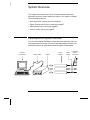
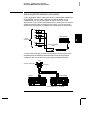
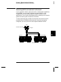
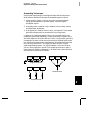
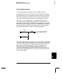
Data Acquisition System Overview
You can use the Agilent 34970A as a stand-alone instrument but there are
many applications where you will want to take advantage of the built-in PC
connectivity features. A typical data acquisition system is shown below.
Computer
and Software
Interface Cable
50
34970A
Plug-in
Modules
System
Cabling
Transducers,
Sensors,
and Events
Chapter 3 System Overview
Data Acquisition System Overview
The system configuration shown on the previous page offers the
following advantages:
• You can use the 34970A to perform data storage, data reduction,
mathematical calculations, and conversion to engineering units.
You can use the PC to provide easy configuration and data presentation.
• You can remove the analog signals and measurement sensors from
the noisy PC environment and electrically isolate them from both the
PC and earth ground.
• You can use a single PC to monitor multiple instruments and
measurement points while performing other PC-based tasks.
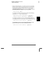
3
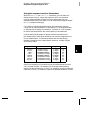
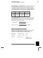
The Computer and Interface Cable
Since computers and operating systems are the subject of many books
and periodicals, they are not discussed in this chapter. In addition to the
computer and operating system, you will need a serial port (RS-232) or
GPIB port (IEEE-488) and an interface cable.
Serial (RS-232)
Advantages
Disadvantages
GPIB (IEEE-488)
Advantages
Disadvantages
Often built into the computer;
no additional hardware is
required.
Cable length is limited
to 45 ft (15 m). *
Speed; faster data and
command transfers.
Cable length is limited
to 60 ft (20 m). *
Drivers usually included in
the operating system.
Only one instrument or
device can be connected
per serial port.
Additional system flexibility,
multiple instruments can
be connected to the
same GPIB port.
Requires an expansion
slot plug-in card in PC
and associated drivers.
Cables readily available
and inexpensive.
Cabling is susceptible to
noise, causing slow or
lost communications.
Direct Memory Transfers
are possible.
Requires special cable.
The 34970A is
shipped with a serial cable
(if internal DMM is ordered).
Varying connector pinouts
and styles.
Data transfers up to
85,000 characters/sec.
Data transfers up to
750,000 characters/sec.
* You can overcome these cable length limitations using special communications hardware.
For example, you can use the Agilent E5810A LAN-to-GPIB Gateway interface or a serial modem.
51
Chapter 3 System Overview
Data Acquisition System Overview
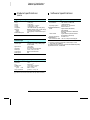
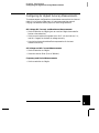
Measurement Software
A variety of software is available to configure your data acquisition
hardware and manipulate and display your measurement data.
Data Logging and Monitoring
Agilent BenchLink Data Logger is a Windows®-based application
designed to make it easy to use the 34970A with your PC for gathering
and analyzing measurements. The software is included with the 34970A
when you order the internal DMM. Use this software to set up your test,
acquire and archive measurement data, and perform real-time display
and analysis of your incoming measurements.
Agilent BenchLink Data Logger
Automated Testing with Multiple Instruments
• Agilent VEE
• TransEra HTBASIC® for Windows
• National Instruments LabVIEW
• Microsoft® Visual Basic or Visual C++
52
Chapter 3 System Overview
Data Acquisition System Overview
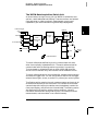
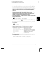
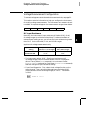
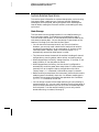
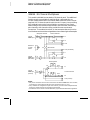
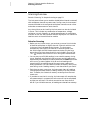
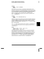
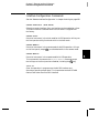
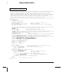
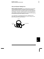
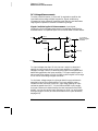
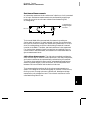
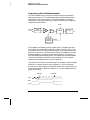
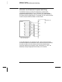
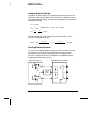
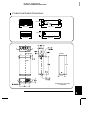
The 34970A Data Acquisition / Switch Unit
As shown below, the logic circuitry for the 34970A is divided into two
sections: earth-referenced and floating. These two sections are isolated
from each other in order to maintain measurement accuracy and
repeatability (for more information on ground loops, see page 341).
External Trigger
Optional
OUT
IN
Alarms
3
Floating
Logic
Control
GPIB
To Computer
Earth
Referenced
Logic
Internal
DMM
Digital
Bus
RS-232
Analog Bus
100
AC Power
200
= Optical Isolators
Plug-In
Slots
300
The earth-referenced and floating circuitry communicate with each
other via an optically-isolated data link. The earth-referenced section
communicates with the floating section to provide PC connectivity.
The instrument is shipped with both an GPIB (IEEE-488) interface
and an RS-232 interface. Only one interface can be enabled at a time.
The earth-referenced section also provides four hardware alarm outputs
and external trigger lines. You can use the alarm output lines to trigger
external alarm lights, sirens, or send a TTL pulse to your control system.
The floating section contains the main system processor and controls all
of the basic functionality of the instrument. This is where the instrument
communicates with the plug-in modules, scans the keyboard, controls the
front-panel display, and controls the internal DMM. The floating section
also performs Mx+B scaling, monitors alarm conditions, converts
transducer measurements to engineering units, time stamps scanned
measurements, and stores data in non-volatile memory.
53
Chapter 3 System Overview
Data Acquisition System Overview
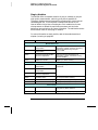
Plug-In Modules
The 34970A offers a complete selection of plug-in modules to give you
high-quality measurement, switching, and control capabilities.
The plug-in modules communicate with the floating logic via the internal
isolated digital bus. The multiplexer modules also connect to the
internal DMM via the internal analog bus. Each module has its own
microprocessor to offload the mainframe processor and minimize
backplane communications for faster throughput. The table below shows
some common uses for each plug-in module.
For more information on each module, refer to the module sections in
chapter 4, starting on page 163.
Model Number
Module Name
Common Uses
Measurement Input
34901A
20-Channel Mux with T/C
Compensation
Scanning and direct measurement of
temperature, voltage, resistance, frequency,
and current (34901A only) using the
internal DMM.
34902A
16-Channel Reed Mux with T/C
Compensation
34908A
40-Channel Single-Ended Mux
with T/C Compensation
Scanning and direct measurement of
temperature, voltage, and resistance using
the internal DMM.
34907A
Multifunction Module
Digital Input, Event Counting.
Signal Routing
34901A
20-Channel Mux with T/C
Compensation
Multiplexing of signals to or from external
instruments.
34902A
16-Channel Reed Mux with T/C
Compensation
34908A
40-Channel Single-Ended Mux
with T/C Compensation
34904A
4x8 Matrix Switch
32 Crosspoint Matrix switching.
34905A
Dual 4-Channel RF Mux (50Ω)
50Ω high-frequency applications (< 2 GHz).
34906A
Dual 4-Channel RF Mux (75Ω)
75Ω high-frequency applications (< 2 GHz).
Control Output
34903A
20-Channel Actuator
General-purpose switching and control
using Form C (SPDT) switches.
34907A
Multifunction Module
Digital Output, Voltage (DAC) Outputs.
54
Chapter 3 System Overview
Data Acquisition System Overview
System Cabling
The plug-in modules have screw-terminal connectors to make it easy to
connect your system cabling. The type of cabling that you use to connect
your signals, transducers, and sensors to the module is critical to
measurement success. Some types of transducers, such as thermocouples,
have very specific requirements for the type of cable that can be used to
make connections. Be sure to consider the usage environment when
choosing wire gauge and insulation qualities. Wire insulation typically
consists of materials such as PVC or Teflon®. The table below lists
several common cable types and describes their typical uses.
Note: Wiring insulation and usage is described in more detail in
“System Cabling and Connections” starting on page 335.
Cable Type
Common Uses
Comments
Thermocouple
Extension Wire
Thermocouple measurements.
Available in specific thermocouple types.
Also available in a shielded cable for
added noise immunity.
Twisted Pair,
Shielded Twisted Pair
Measurement inputs, voltage
outputs, switching, counting.
Most common cable for low-frequency
measurement inputs. Twisted pair
reduces common mode noise.
Shielded-twisted pair provides additional
noise immunity.
Shielded Coaxial,
Double-Shielded
Coaxial
VHF signal switching.
Most common cable for high-frequency
signal routing. Available in specific
impedance values (50Ω or 75Ω).
Provides excellent noise immunity.
Double-shielded cable improves
isolation between channels. Requires
special connectors.
Flat Ribbon,
Twisted Pair Ribbon
Digital Input/Output
Often used with mass termination
connectors. These cables provide little
noise immunity.
Teflon is a registered trademark of E.I. duPont deNemours and Company.
55
3
Chapter 3 System Overview
Data Acquisition System Overview
Transducers and Sensors
Transducers and sensors convert a physical quantity into an electrical
quantity. The electrical quantity is measured and the result is then
converted to engineering units. For example, when measuring a
thermocouple, the instrument measures a dc voltage and mathematically
converts it to a corresponding temperature in °C, °F, or K.
Measurement
Temperature
Typical Transducer Types
Typical Transducer Output
Thermocouple
0 mV to 80 mV
RTD
2-wire or 4-wire resistance
from 5Ω to 500Ω
Thermistor
2-wire resistance from
10Ω to 1 MΩ
Pressure
Solid State
±10 Vdc
Flow
Rotary Type
Thermal Type
4 mA to 20 mA
Strain
Resistive Elements
4-wire resistance from
10Ω to 10 kΩ
Events
Limit Switches
Optical Counters
Rotary Encoder
0V or 5V Pulse Train
Digital
System Status
TTL Levels
Alarm Limits
The 34970A has four alarm outputs which you can configure to alert you
when a reading exceeds specified limits on a channel during a scan.
You can assign a high limit, a low limit, or both to any configured
channel in the scan list. You can assign multiple channels to any of the
four available alarms (numbered 1 through 4). For example, you can
configure the instrument to generate an alarm on Alarm 1 when a limit
is exceeded on any of channels 103, 205, or 320.
You can also assign alarms to channels on the multifunction module.
For example, you can generate an alarm when a specific bit pattern or
bit pattern change is detected on a digital input channel or when a specific
count is reached on a totalizer channel. With the multifunction module,
the channels do not have to be part of the scan list to generate an alarm.
56
Chapter 3 System Overview
Signal Routing and Switching
Signal Routing and Switching
The switching capabilities of the plug-in modules available with the
34970A provide test system flexibility and expandability. You can use
the switching plug-in modules to route signals to and from your test
system or multiplex signals to the internal DMM or external instruments.
Relays are electromechanical devices which are subject to wear-out
failure modes. The life of a relay, or the number of actual operations
before failure, is dependent upon how it is used – applied load, switching
frequency, and environment. The 34970A Relay Maintenance System
automatically counts the cycles of each relay in the instrument and
stores the total count in non-volatile memory on each switch module.
Use this feature to track relay failures and to predict system maintenance
requirements. For more information on using this feature, refer to
“Relay Cycle Count” on page 147.
Switching Topologies
Several switching plug-in modules are available with different
topologies for various applications. The following switching topologies
are available:
• Multiplexer (34901A, 34902A, 34905A, 34906A, 34908A)
• Matrix (34904A)
• Form C – Single Pole, Double Throw (34903A)
The following sections describe each of these switching topologies.
57
3
Chapter 3 System Overview
Signal Routing and Switching
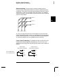
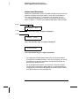
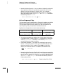
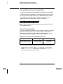
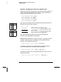
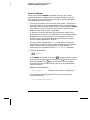
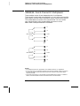
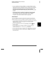
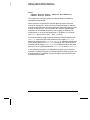
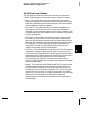
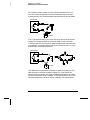
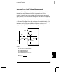
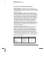
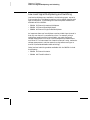
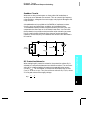
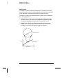
Multiplexer Switching Multiplexers allow you to connect one of
multiple channels to a common channel, one at a time. A simple 4-to-1
multiplexer is shown below. When you combine a multiplexer with a
measurement device, like the internal DMM, you create a scanner.
For more information on scanning, see page 62.
Channel 1
Common
Channel 2
Channel 3
Channel 4
Multiplexers are available in several types:
• One-Wire (Single-Ended) Multiplexers for common LO measurements.
For more information, see page 379.
• Two-Wire Multiplexers for floating measurements. For more
information, see page 379.
• Four-Wire Multiplexers for resistance and RTD measurements.
For more information, see page 380.
• Very High Frequency (VHF) Multiplexers for switching frequencies
up to 2.8 GHz. For more information, see page 390.
58
Chapter 3 System Overview
Signal Routing and Switching
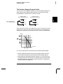
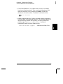
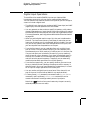
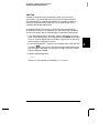
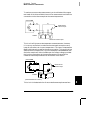
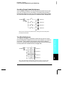
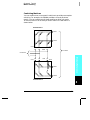
Matrix Switching A matrix switch connects multiple inputs to
multiple outputs and therefore offers more switching flexibility than a
multiplexer. Use a matrix for switching low-frequency (less than 10 MHz)
signals only. A matrix is arranged in rows and columns. For example,
a simple 3x3 matrix could be used to connect three sources to three test
points as shown below.
Source 1
3
Source 2
Source 3
Test 1
Test 2
Test 3
Any one of the signal sources can be connected to any one of the test
inputs. Be aware that with a matrix, it is possible to connect more than
one source at the same time. It is important to make sure that dangerous
or unwanted conditions are not created by these connections.
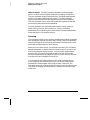
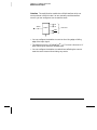
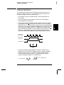
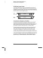
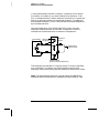
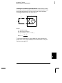
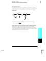
Form C (SPDT) Switching The 34903A Actuator contains 20 Form C
switches (also called single-pole, double-throw). You can use Form C
switches to route signals but they are typically used to control external
devices.
Channel Open
(NC Contact Connected)
NO = Normally Open
NC = Normally Closed
Channel Closed
(NO Contact Connected)
NO
NO
NC
NC
COM
COM
59
Chapter 3 System Overview
Measurement Input
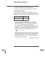
Measurement Input
The 34970A allows you to combine a DMM (either internal or external)
with multiplexer channels to create a scan. During a scan, the instrument
connects the DMM to the configured multiplexer channels one at a time
and makes a measurement on each channel.
Any channel that can be “read” by the instrument can also be included
in a scan. This includes any combination of temperature, voltage,
resistance, current, frequency, or period measurements on multiplexer
channels. A scan can also include a read of a digital port or a read of the
totalizer count on the multifunction module.
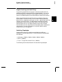
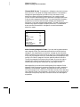
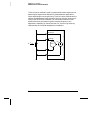
The Internal DMM
A transducer or sensor converts a physical quantity being measured
into an electrical signal which can be measured by the internal DMM.
To make these measurements, the internal DMM incorporates the
following functions:
• Temperature (thermocouple, RTD, and thermistor)
• Voltage (dc and ac up to 300V)
• Resistance (2-wire and 4-wire up to 100 MΩ)
• Current (dc and ac up to 1A)
• Frequency and Period (up to 300 kHz)
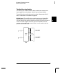
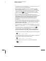
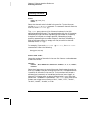
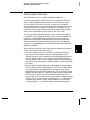
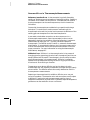
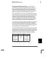
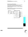
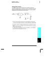
The internal DMM provides a universal input front-end for measuring
a variety of transducer types without the need for additional external
signal conditioning. The internal DMM includes signal conditioning,
amplification (or attenuation), and a high resolution (up to 22 bits)
analog-to-digital converter. A simplified diagram of the internal DMM is
shown below.
Analog
Input
Signal
Signal
Conditioning
Amp
Analog to
Digital
Converter
Main
Processor
To / From
Earth
Referenced
Section
= Optical Isolators
60
Chapter 3 System Overview
Measurement Input
Signal Conditioning, Ranging, and Amplification Analog input
signals are multiplexed into the internal DMM’s signal-conditioning
section – typically comprising switching, ranging, and amplification
circuitry. If the input signal is a dc voltage, the signal conditioner
is composed of an attenuator for the higher input voltages and a
dc amplifier for the lower input voltages. If the input signal is an
ac voltage, a converter is used to convert the ac signal to its equivalent
dc value (true RMS value). Resistance measurements are performed by
supplying a known dc current to an unknown resistance and measuring
the dc voltage drop across the resistor. The input signal switching and
ranging circuitry, together with the amplifier circuitry, convert the
input to a dc voltage which is within the measuring range of the
internal DMM’s analog-to-digital converter (ADC).
You can allow the instrument to automatically select the measurement
range using autoranging or you can select a fixed measurement range
using manual ranging. Autoranging is convenient because the instrument
automatically decides which range to use for each measurement based
on the input signal. For fastest scanning operation, use manual ranging
for each measurement (some additional time is required for autoranging
since the instrument has to make a range selection).
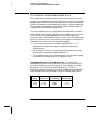
Analog-to-Digital Conversion (ADC) The ADC takes a prescaled
dc voltage from the signal-conditioning circuitry and converts it to digital
data for output and display on the front panel. The ADC governs some of
the most basic measurement characteristics. These include measurement
resolution, reading speed, and the ability to reject spurious noise. There
are several analog-to-digital conversion techniques but they can be
divided into two types: integrating and non-integrating. The integrating
techniques measure the average input value over a defined time
interval, thus rejecting many noise sources. The non-integrating
techniques sample the instantaneous value of the input, plus noise,
during a very short interval. The internal DMM uses an integrating
ADC technique.
You can select the resolution and reading speed from 6 digits (22 bits) at
3 readings per second to 4 digits (16 bits) at up to 600 readings per second.
The Advanced menu from the 34970A front panel allows you to control
the integration period for precise rejection of noise signals.
61
3
Chapter 3 System Overview
Measurement Input
Main Processor The main processor, located in the floating logic
section, controls the input signal conditioning, ranging, and the ADC.
The main processor accepts commands from, and sends measurement
results to, the earth-referenced logic section. The main processor
synchronizes measurements during scanning and control operations.
The main processor uses a multi-tasking operating system to manage
the various system resources and demands.
The main processor also calibrates measurement results, performs
Mx+B scaling, monitors alarm conditions, converts transducer
measurements to engineering units, time stamps scanned measurements,
and stores data in non-volatile memory.
Scanning
The instrument allows you to combine a DMM (either internal or external)
with multiplexer channels to create a scan. During a scan, the instrument
connects the DMM to the configured multiplexer channels one at a time
and makes a measurement on each channel.
Before you can initiate a scan, you must set up a scan list to include all
desired multiplexer or digital channels. Channels which are not in the
scan list are skipped during the scan. The instrument automatically
scans the list of channels in ascending order from slot 100 through
slot 300. Measurements are taken only during a scan and only on those
channels which are included in the scan list.
You can store up to 50,000 readings in non-volatile memory during
a scan. Readings are stored only during a scan and all readings are
automatically time stamped. Each time you start a new scan, the
instrument clears all readings stored in memory from the previous scan.
Therefore, all readings currently stored in memory are from the most
recent scan.
62
Chapter 3 System Overview
Measurement Input
You can configure the event or action that controls the onset of each
sweep through the scan list (a sweep is one pass through the scan list):
• You can set the instrument’s internal timer to automatically scan at
a specific interval as shown below. You can also program a time delay
between channels in the scan list.
Scan Count
(1 to 50,000 scans, or continuous)
3
Scan List (1 sweep)
t
Scan-to-Scan Interval
(0 to 99:59:59 hours)
• You can manually control a scan by repeatedly pressing
the front panel.
from
• You can start a scan by sending a software command from the
remote interface.
• You can start a scan when an external TTL trigger pulse is received.
• You can start a scan when an alarm condition is logged on the
channel being monitored.
63
Chapter 3 System Overview
Measurement Input
Scanning With External Instruments
If your application doesn’t require the built-in measurement capabilities
of the 34970A, you can order it without the internal DMM. In this
configuration, you can use the 34970A for signal routing or control
applications. If you install a multiplexer plug-in module, you can use the
34970A for scanning with an external instrument. You can connect an
external instrument (such as a DMM) to the multiplexer COM terminal.
H
L
H
Input
Channels
External DMM
L
H
Common Terminals
(COM)
L
H
L
To control scanning with an external instrument, two control lines are
provided. When the 34970A and the external instrument are properly
configured, you can synchronize a scan sequence between the two.
GND
Channel Closed OUT
Ext Trig IN
External DMM
34970A
VM Complete OUT
64
Ext Trig IN
Chapter 3 System Overview
Measurement Input
The Multifunction Module
The multifunction module (34907A) adds two additional measurement
input capabilities to the system: digital input and event totalize.
The multifunction module also contains a dual voltage output (DAC)
which is described in more detail on page 68.
Digital Input The multifunction module has two non-isolated 8-bit
input/output ports which you can use for reading digital patterns.
You can read the live status of the bits on the port or you can configure
a scan to include a digital read. Each port has a separate channel
number on the module and contains 8-bits. You can combine the two
ports to read a 16-bit word.
Bit 0
8
Port 1 (LSB)
Channel 01
Digital
Input
Bit 7
Bit 0
8
Port 2 (MSB)
Channel 02
Bit 7
65
3
Chapter 3 System Overview
Measurement Input
Totalizer The multifunction module has a 26-bit totalizer which can
count pulses at a 100 kHz rate. You can manually read the totalizer
count or you can configure a scan to read the count.
+IN
-IN
26 Bits
Channel 03
Totalize
Gate
Gate
• You can configure the totalizer to count on the rising edge or falling
edge of the input signal.
• The maximum count is 67,108,863 (226- 1). The count rolls over to “0”
after reaching the maximum allowed value.
• You can configure the totalizer to read without affecting the count or
reset the count to zero without losing any counts.
66
Chapter 3 System Overview
Control Output
Control Output
In addition to signal routing and measurement, you can also use the
34970A to provide simple control outputs. For example, you can control
external high-power relays using the actuator module or a digital output
channel.
The Multifunction Module
3
The multifunction module (34907A) adds two additional control output
capabilities to the system: digital output and voltage (DAC) output.
The multifunction module also contains digital input and event totalizer
capabilities which are described in more detail on pages 65 and 66.
Digital Output The multifunction module has two non-isolated 8-bit
input/output ports which you can use to output digital patterns. Each
port has a separate channel number on the module and contains 8-bits.
You can combine the two ports to output a 16-bit word.
Bit 0
8
Port 1 (LSB)
Channel 01
Digital
Output
Bit 7
Bit 0
8
Port 2 (MSB)
Channel 02
Bit 7
67
Chapter 3 System Overview
Control Output
Voltage (DAC) Output The multifunction module has two analog
outputs capable of outputting calibrated voltages between ±12 volts with
16 bits of resolution. Each DAC (Digital-to-Analog Converter) channel can
be used as a programmable voltage source for analog input control of
other devices. A simplified diagram is shown below.
16
DAC 1
Channel 04
DAC 2
Channel 05
16
• You can set the output voltage to any value between +12 Vdc and
-12 Vdc, in 1 mV steps. Each DAC is earth referenced, it cannot float.
• Each DAC channel is capable of supplying 10 mA maximum current.
Note: You must limit the output current to 40 mA total for all three
slots (six DAC channels).
68
Chapter 3 System Overview
Control Output
The Actuator / General-Purpose Switch
You can think of the 34903A Actuator as a control output because it is
often used to control external power devices. The actuator provides
20 independent, isolated Form C (SPDT) switches.
Channel Open
(NC Contact Connected)
NO = Normally Open
NC = Normally Closed
Channel Closed
(NO Contact Connected)
NO
NO
NC
NC
COM
COM
3
Each channel can switch up to 300V dc or ac rms. Each switch can also
switch up to 1 A dc or ac rms up to 50 W maximum. For example, the
maximum current that you can switch at 120 V is 0.45 A as shown below.
Voltage
Current
For control applications, the actuator has the following advantages:
• Higher voltage and power rating than the digital output channels.
The actuator switches can also be used to control power devices.
• When used with high-power devices, however, it is critical that you
provide protection to the switch from capacitive and inductive loads
to ensure maximum relay life (for more information on attenuators,
see the discussion on page 387).
69
70
4
4
Features and
Functions
Features and Functions
You will find that this chapter makes it easy to look up all the details
about a particular feature of the 34970A. Whether you are operating
the instrument from the front panel or over the remote interface, this
chapter will be useful. This chapter is divided into the following sections:
• SCPI Language Conventions, on page 73
• Scanning, starting on page 74
• Single-Channel Monitoring, starting on page 93
• Scanning With External Instruments, starting on page 95
• General Measurement Configuration, starting on page 98
• Temperature Measurement Configuration, starting on page 106
• Voltage Measurement Configuration, starting on page 113
• Resistance Measurement Configuration, on page 115
• Current Measurement Configuration, starting on page 116
• Frequency Measurement Configuration, starting on page 118
• Mx+B Scaling, starting on page 119
• Alarm Limits, starting on page 122
• Digital Input Operations, starting on page 133
• Totalizer Operations, starting on page 135
• Digital Output Operations, on page 138
• DAC Output Operations, on page 139
• System-Related Operations, starting on page 140
• Remote Interface Configuration, starting on page 150
• Calibration Overview, starting on page 155
• Factory Reset State, on page 160
• Instrument Preset State, on page 161
• Multiplexer Module Default Settings, on page 162
• Module Overview, on page 163
• 34901A 20-Channel Multiplexer, starting on page 164
• 34902A 16-Channel Multiplexer, starting on page 166
• 34903A 20-Channel Actuator, starting on page 168
• 34904A 4x8 Matrix Switch, starting on page 170
• 34905A/6A Dual 4-Channel RF Multiplexers, starting on page 172
• 34907A Multifunction Module, starting on page 174
• 34908A 40-Channel Single-Ended Multiplexer, starting on page 176
72
Chapter 4 Features and Functions
SCPI Language Conventions
SCPI Language Conventions
Throughout this manual, the following conventions are used for
SCPI command syntax for remote interface programming:
• Square brackets ( [ ] ) indicate optional keywords or parameters.
• Braces ( { } ) enclose parameter choices within a command string.
• Triangle brackets ( < > ) enclose parameters for which you must
substitute a value.
• A vertical bar ( | ) separates multiple parameter choices.
Rules for Using a Channel List
Many of the SCPI commands for the 34970A include a scan_list
or ch_list parameter which allow you to specify one or more channels.
The channel number has the form (@scc), where s is the slot number
(100, 200, or 300) and cc is the channel number. You can specify a single
channel, multiple channels, or a range of channels as shown below.
4
• The following command configures a scan list to include only
channel 10 on the module in slot 300.
ROUT:SCAN (@310)
• The following command configures a scan list to include multiple
channels on the module in slot 200. The scan list now contains only
channels 10, 12, and 15 (the scan list is redefined each time you send
a new ROUTe:SCAN command).
ROUT:SCAN (@ 210,212,215)
• The following command configures a scan list to include a range of
channels. When you specify a range of channels, the range may
contain invalid channels (they are ignored), but the first and last
channel in the range must be valid. The scan list now contains
channels 5 through 10 (slot 100) and channel 15 (slot 200).
ROUT:SCAN (@ 105:110,215)
73
Chapter 4 Features and Functions
Scanning
Scanning
The instrument allows you to combine a DMM (either internal or external)
with multiplexer channels to create a scan. During a scan, the instrument
connects the DMM to the configured multiplexer channels one at a time
and makes a measurement on each channel.
Any channel that can be “read” by the instrument can also be included
in a scan. This includes any combination of temperature, voltage,
resistance, current, frequency, or period measurements on multiplexer
channels. A scan can also include a read of a digital port or a read of the
totalizer count on the multifunction module. Scanning is allowed with
the following modules:
•
•
•
•
34901A
34902A
34907A
34908A
20-Channel Multiplexer
16-Channel Multiplexer
Multifunction Module (digital input and totalizer only)
40-Channel Single-Ended Multiplexer
Automated scanning is not allowed with the actuator module, the matrix
module, or the RF multiplexer modules. In addition, a scan cannot
include a write to a digital port or a voltage output from a DAC channel.
However, you can write your own program to manually create a “scan”
to include these operations.
Rules for Scanning
• Before you can initiate a scan, you must set up a scan list to include
all desired multiplexer or digital channels. Channels which are not
in the scan list are skipped during the scan. The instrument
automatically scans the list of channels in ascending order from
slot 100 through slot 300. Measurements are taken only during a
scan and only on those channels which are included in the scan list.
The “ ” (sample) annunciator turns on during each measurement.
• You can store up to 50,000 readings in non-volatile memory during
a scan. Readings are stored only during a scan and all readings are
automatically time stamped. If memory overflows (the MEM annunciator
will turn on), a status register bit is set and new readings will
overwrite the first readings stored (the most recent readings are
always preserved). You can read the contents of memory at any time,
even during a scan. Reading memory is not cleared when you read it.
74
Chapter 4 Features and Functions
Scanning
• Each time you start a new scan, the instrument clears all readings
(including alarm data) stored in reading memory from the previous
scan. Therefore, the contents of memory are always from the most
recent scan.
• While a scan is running, the instrument automatically stores the
minimum and maximum readings and calculates the average for each
channel. You can read these values at any time, even during a scan.
• Mx+B scaling and alarm limits are applied to measurements during a
scan and all data is stored in non-volatile memory. You can read the
contents of reading memory or the alarm queue at any time, even
during a scan.
• In the Monitor function, the instrument takes readings as often as it
can on a single channel, even during a scan (see “Single-Channel
Monitoring” on page 93). This feature is useful for troubleshooting
your system before a test or for watching an important signal.
• If you abort a scan that is running, the instrument will complete the
one measurement in progress (the entire scan will not be completed)
and the scan will stop. You cannot resume the scan from where it
left off. If you initiate a new scan, all readings are cleared from memory.
• When you add a multiplexer channel to a scan list, that entire module
is dedicated to the scan. The instrument issues a Card Reset to open
all channels on that module. You cannot perform low-level close or
open operations on any channels on that module (even those channels
that are not configured).
• While a scan is running, you can perform some low-level control
operations on modules that do not contain channels in the scan list.
For example, you can open or close channels or issue a Card Reset
on switching modules that do not contain channels in the scan list.
However, you cannot change any parameters that affect the scan
(channel configuration, scan interval, scaling values, alarm limits,
Card Reset, etc.) while a scan is running.
75
4
Chapter 4 Features and Functions
Scanning
• When you add a digital read (multifunction module) to a scan list,
that port is dedicated to the scan. The instrument issues a Card
Reset to make that port an input port (the other port is not affected).
• While a scan is running, you can perform low-level control operations
on any channels on the multifunction module that are not in the scan.
For example, you can output a DAC voltage or write to a digital port
(even if the totalizer is part of the scan list). However, you cannot
change any parameters that affect the scan (channel configuration,
scan interval, Card Reset, etc.) while a scan is running.
• If a scan includes a read of the totalizer, multifunction module,
the count is reset each time it is read during the scan only when the
totalizer reset mode is enabled (TOTalize:TYPE RRESet command
or the Advanced menu for the totalizer).
• If you install a module while a scan is running, the instrument will
cycle power and resume scanning. If you remove a module while a
scan is running, the instrument will cycle power and resume
scanning (even if the removed module was part of the scan list).
• You can use either the internal DMM or an external DMM to make
measurements of your configured channels. However, the instrument
allows only one scan list at a time; you cannot scan some channels
using the internal DMM and others using an external DMM.
Readings are stored in 34970A memory only when the internal DMM
is used.
• If the internal DMM is installed and enabled, the instrument will
automatically use it for scanning. For externally-controlled scans,
you must either remove the internal DMM from the 34970A
or disable it (see “Internal DMM Disable” on page 145).
76
Chapter 4 Features and Functions
Scanning
Power Failure
• When shipped from the factory, the instrument is configured to
automatically recall the power-down state when power is restored.
In this configuration, the instrument will automatically recall the
instrument state at power-down and resume a scan in progress.
If you do not want the power-down state to be recalled when power
is restored, send the MEMory:STATe:RECall:AUTO OFF command
(also see the Utility menu); a Factory Reset (*RST command) is then
issued when power is restored.
Sweep 1:
Sweep 2:
Sweep 3:
Power Fails
• If the instrument is in the middle of a scan sweep when power fails,
all readings from that partially completed sweep will be discarded
(a sweep is one pass through the scan list). For example, assume that
your scan list includes four multiplexer channels and you want to
sweep through the scan list three times (see diagram). A power
failure occurs after the second reading in the third scan sweep.
The instrument will discard the last two of the 10 readings and will
resume scanning at the beginning of the third scan sweep.
• If you remove a module or move a module to a different slot while
power is off, the scan will not resume when power is restored.
No error is generated.
• If you replace a module with a module of the same type while power
is off, the instrument will continue scanning when power is restored.
No error is generated.
77
4
Chapter 4 Features and Functions
Scanning
Adding Channels to a Scan List
Before you can initiate a scan, you must configure the channels to be
scanned and set up a scan list (these two operations occur simultaneously
from the front panel). The instrument automatically scans the
configured channels in ascending order from slot 100 through slot 300.
To Build a Scan List From the Front Panel:
To add the active channel to the scan list, press
. Select the
function, range, resolution, and other measurement parameters for this
channel. You can also press
to sequentially step through the scan
list and take a measurement on each channel (readings are not stored in
memory). This is an easy way to verify your wiring connections and
channel configuration (also valid during a scan).
• When you reconfigure a channel and add it to the scan list, it is
important to note that the previous configuration on that channel
is lost. For example, assume that a channel is configured for
dc voltage measurements. When you reconfigure that channel for
thermocouple measurements, the previous range, resolution, and
channel delay are set to their Factory Reset (*RST command) state.
• To remove the active channel from the scan list, press
and select
CHANNEL OFF. If you decide to add that channel back to the scan list
with the same function, the original channel configuration (including
scaling and alarm values) is still present.
• To initiate a scan and store all readings in memory, press
(the SCAN annunciator will turn on). Each time you initiate a
new scan, the instrument clears all previously stored readings.
• To stop a scan, press and hold
78
.
Chapter 4 Features and Functions
Scanning
To Build a Scan List From the Remote Interface:
• The MEASure?, CONFigure, and ROUTe:SCAN commands contain a
scan_list parameter which defines the list of channels in the scan list.
Note that each time you send one of these commands, it redefines the
scan list. To determine which channels are currently in the scan list,
you can send the ROUTe:SCAN? query command.
• To initiate a scan, execute the MEASure?, READ?, or INITiate
command. The MEASure? and READ? commands send readings
directly to the instrument’s output buffer but readings are not stored
in memory. The INITiate command stores readings in memory.
Use the FETCh? command to retrieve stored readings from memory.
See the examples starting on page 201 in chapter 5 for more
information on using these commands.
• When you reconfigure a channel and add it to the scan list using
MEASure? or CONFigure, it is important to note that the previous
configuration on that channel is lost. For example, assume that a
channel is configured for dc voltage measurements. When you
reconfigure that channel for thermocouple measurements,
the previous range, resolution, and channel delay are set to their
Factory Reset (*RST command) state.
4
• Each time you initiate a new scan, the instrument clears all
previously stored readings.
• To stop a scan, execute the ABORt command.
79
Chapter 4 Features and Functions
Scanning
Scan Interval
You can configure the event or action that controls the onset of each
sweep through the scan list (a sweep is one pass through the scan list):
• You can set the instrument’s internal timer to automatically scan at a
specific interval. You can also program a time delay between
channels in the scan list.
• You can manually control a scan by repeatedly pressing
the front panel.
from
• You can start a scan by sending a software command from the
remote interface (MEASure? or INITiate command).
• You can start a scan when an external TTL trigger pulse is received.
• You can start a scan when an alarm event is logged on the channel
being monitored.
Interval Scanning In this configuration, you control the frequency of
scan sweeps by selecting a wait period from the start of one sweep to the
start of the next sweep (called the scan-to-scan interval). The countdown time is shown on the front-panel display between one scan sweep
and the start of the next sweep. If the scan interval is less than the time
required to measure all channels in the scan list, the instrument will
scan continuously, as fast as possible (no error is generated).
Scan Count
(1 to 50,000 scans, or continuous)
Scan List (1 sweep)
t
Scan-to-Scan Interval
(0 to 99:59:59 hours)
80
Chapter 4 Features and Functions
Scanning
• You can set the scan interval to any value between 0 seconds
and 99:59:59 hours (359,999 seconds), with 1 ms resolution.
• Once you have initiated the scan, the instrument will continue
scanning until you stop it or until the scan count is reached.
See “Scan Count” on page 86 for more information.
• Mx+B scaling and alarm limits are applied to measurements during
a scan and all data is stored in non-volatile memory.
• The MEASure? and CONFigure commands automatically set the
scan interval to immediate (0 seconds) and the scan count to 1 sweep.
• From the front panel, a Factory Reset (Sto/Rcl menu) sets the scan
interval to 10 seconds and the scan count to continuous. From the
remote interface, a Factory Reset (*RST command) sets the
scan interval to immediate (0 seconds) and the scan count to 1 sweep.
• Front-Panel Operation: To select interval scanning and set a scan
interval time (hour:minutes:seconds), choose the following item.
4
INTERVAL SCAN
To initiate the scan and store all readings in memory, press
(the SCAN annunciator will turn on). Between scan sweeps,
the count-down time is shown on the front-panel (00:04 TO SCAN).
Note: To stop a scan, press and hold
.
• Remote Interface Operation: The following program segment
configures the instrument for an interval scan.
TRIG:SOURCE TIMER
TRIG:TIMER 5
TRIG:COUNT 2
INIT
Select the interval timer configuration
Set the scan interval to 5 seconds
Sweep the scan list 2 times
Initiate the scan
Note: To stop a scan, send the ABORt command.
81
Chapter 4 Features and Functions
Scanning
Scan Once In this configuration, the instrument waits for either a
front-panel key press or a remote interface command before sweeping
through the scan list.
• All readings from the scan are stored in non-volatile memory.
Readings accumulate in memory until the scan is terminated (until the
scan count is reached or until you abort the scan).
• You can specify a scan count which sets the number of front-panel
key presses or scan trigger commands that will be accepted before
terminating the scan. See “Scan Count” on page 86 for more
information.
• Mx+B scaling and alarm limits are applied to measurements during
a Scan Once operation and all data is stored in non-volatile memory.
• Front-Panel Operation:
MANUAL SCAN
To initiate the scan and store all readings in memory, press
.
The ONCE annunciator turns on as a reminder that a Scan Once
operation is in progress.
Note: To stop a scan, press and hold
.
• Remote Interface Operation: The following program segment
configures the instrument for a Scan Once operation.
TRIG:SOURCE BUS
TRIG:COUNT 2
INIT
Select the bus (once) configuration
Sweep the scan list 2 times
Initiate the scan
Then, send the *TRG (trigger) command to begin each scan sweep.
You can also trigger the instrument from the GPIB interface by
sending the IEEE-488 Group Execute Trigger (GET) message.
The following statement shows how to send a GET message.
TRIGGER 709
Group Execute Trigger
Note: To stop a scan, send the ABORt command.
82
Chapter 4 Features and Functions
Scanning
External Scanning In this configuration, the instrument sweeps
through the scan list once each time a low-going TTL pulse is received
on the rear-panel Ext Trig Input line (pin 6).
Input
5V
0V
Ext Trig Input
Gnd
> 1 µs
Ext Trig Connector
• You can specify a scan count which sets the number of external
pulses the instrument will accept before terminating the scan.
See “Scan Count” on page 86 for more information.
4
• If the instrument receives an external trigger before it is ready to
accept one, it will buffer one trigger before generating an error.
• All readings from the scan are stored in non-volatile memory.
Readings accumulate in memory until the scan is terminated
(until the scan count is reached or until you abort the scan).
• Mx+B scaling and alarm limits are applied to measurements during
the scan and all data is stored in non-volatile memory.
• Front-Panel Operation:
EXTERNAL SCAN
To initiate the scan, press
. The EXT annunciator turns on as a
reminder that an External Scan is in progress. When a TTL pulse is
received, the scan starts and readings are stored in memory. To stop
a scan, press and hold
.
• Remote Interface Operation: The following program segment
configures the instrument for an External Scan.
TRIG:SOURCE EXT
TRIG:COUNT 2
INIT
Select the external trigger configuration
Sweep the scan list 2 times
Initiate the scan
Note: To stop a scan, send the ABORt command.
83
Chapter 4 Features and Functions
Scanning
Scanning on Alarm In this configuration, the instrument sweeps the
scan list once each time a reading crossing an alarm limit on a channel.
You can also assign alarms to channels on the multifunction module.
For example, you can generate an alarm when a specific bit pattern
is detected or when a specific count is reached.
Note: For complete details on configuring and using alarms, refer to
“Alarm Limits” starting on page 122.
• In this scan configuration, you may use the Monitor function to
continuously take readings on a selected channel and wait for an
alarm on that channel. The monitored channel can be part of the scan
list but you can also use a channel on the multifunction module
(which does not have to be part of the scan list and you do not have to
use the Monitor function). For example, you can generate an alarm
on a totalizer channel which will initiate a scan when a specific count
is reached.
• You can specify a scan count which sets the number of alarms that
will be allowed before terminating the scan. See “Scan Count”
on page 86 for more information.
• All readings from the scan are stored in non-volatile memory.
Readings accumulate in memory until the scan is terminated
(until the scan count is reached or until you abort the scan).
• Mx+B scaling and alarm limits are applied to measurements during
the scan and all data is stored in non-volatile memory.
• Front-Panel Operation:
SCAN ON ALARM
To enable the Monitor function select the desired channel and then
press
. To initiate the scan, press
. When an alarm event
occurs, the scan starts and readings are stored in memory.
Note: To stop a scan, press and hold
84
.
Chapter 4 Features and Functions
Scanning
• Remote Interface Operation: The following program segment configures
the instrument to scan when an alarm occurs.
TRIG:SOURCE ALARM1
TRIG:COUNT 2
Select the alarm configuration
Sweep the scan list 2 times
Set the upper limit
CALC:LIM:UPPER 5,(@103)
CALC:LIM:UPPER:STATE ON,(@103) Enable the upper limit
OUTPUT:ALARM1:SOURCE (@103)
Report alarms on Alarm 1
ROUT:MON (@103)
ROUT:MON:STATE ON
Select monitor channel
Enable monitoring
INIT
Initiate the scan
Note: To stop a scan, send the ABORt command.
4
85
Chapter 4 Features and Functions
Scanning
Scan Count
You can specify the number of times the instrument will sweep through
the scan list. When the specified number of sweeps have occurred, the
scan stops.
• Select a scan count between 1 to 50,000 scan sweeps, or continuous.
• During an Interval Scan (see page 80), the scan count sets the number
of times the instrument will sweep through the scan list and therefore
determines the overall duration of the scan.
• During a Scan Once operation (see page 82), the scan count sets the
number of front-panel key presses or scan trigger commands that will
be accepted before terminating the scan.
• During an External Scan (see page 83), the scan count sets the
number of external trigger pulses that will be accepted before
terminating the scan.
• During an Alarm Scan (see page 84), the scan count sets the number
of alarms that will be allowed before terminating the scan.
• You can store up to 50,000 readings in non-volatile memory during
a scan. If you set a continuous scan and memory overflows (the MEM
annunciator will turn on), a status register bit is set and new
readings will overwrite the first readings stored (the most recent
readings are always preserved).
• The MEASure? and CONFigure commands automatically set the
scan count to 1.
• From the front panel, a Factory Reset (Sto/Rcl menu) sets the scan
count to continuous. From the remote interface, a Factory Reset
(*RST command) sets the scan count to 1 sweep.
• Front-Panel Operation:
00020 SCANS
The default is CONTINUOUS. To set the count to a value between
1 and 50,000 scans, turn the knob clockwise and enter a number.
• Remote Interface Operation:
TRIG:COUNT 20
Note: To configure a continuous scan, send TRIG:COUNT INFINITY.
86
Chapter 4 Features and Functions
Scanning
Reading Format
During a scan, the instrument automatically adds a time stamp to
all readings and stores them in non-volatile memory. Each reading is
stored with measurement units, time stamp, channel number, and
alarm status information. From the remote interface, you can specify
which information you want returned with the readings (from the front
panel, all of the information is available for viewing). The reading
format applies to all readings being removed from the instrument from
a scan; you cannot set the format on a per-channel basis.
• From the remote interface, the time stamp information is returned
either in absolute time (time of day with date) or relative time
(time since start of scan). Use the FORMat:READ:TIME:TYPE
command to select absolute or relative time. From the front panel,
the time stamp is always returned in absolute time.
• The MEASure? and CONFigure commands automatically turn off the
units, time, channel, and alarm information.
• A Factory Reset (*RST command) turns off the units, time, channel,
and alarm information.
• Remote Interface Operation: The following commands select the
format of readings returned from a scan.
FORMat:READing:ALARm ON
FORMat:READing:CHANnel ON
FORMat:READing:TIME ON
FORMat:READing:TIME:TYPE {ABSolute|RELative}
FORMat:READing:UNIT ON
The following is an example of a reading stored in memory with all
fields enabled (relative time is shown).
1 Reading with Units (26.195 °C)
2 Time Since Start of Scan (17 ms)
3 Channel Number
4 Alarm Limit Threshold Crossed
(0 = No Alarm, 1 = LO, 2 = HI)
87
4
Chapter 4 Features and Functions
Scanning
Channel Delay
You can control the pace of a scan sweep by inserting a delay between
multiplexer channels in the scan list (useful for high-impedance or
high-capacitance circuits). The delay is inserted between the relay
closure and the actual measurement on the channel. The programmed
channel delay overrides the default channel delay that the instrument
automatically adds to each channel.
Scan List
t
Ch 1 Ch 2 Ch 3 Ch 4 Ch 5 Ch 6
t
Channel Delay
• You can set the channel delay to any value between 0 seconds and
60 seconds, with 1 ms resolution. You can select a different delay for
each channel. The default channel delay is automatic; the instrument
determines the delay based on function, range, integration time,
and ac filter setting (see “Automatic Channel Delays” on the next page).
• The MEASure? and CONFigure commands set the channel delay
to automatic. A Factory Reset (*RST command) also sets the channel
delay to automatic.
• Front-Panel Operation:
CH DELAY TIME
• Remote Interface Operation: The following command adds a 2-second
channel delay to channel 101.
ROUT:CHAN:DELAY 2,(@101)
88
Chapter 4 Features and Functions
Scanning
Automatic Channel Delays
If you do not specify a channel delay, the instrument selects a delay
for you. The delay is determined by function, range, integration time,
and ac filter setting as shown below.
DC Voltage, Thermocouple, DC Current (for all ranges):
Integration Time
PLC > 1
PLC ≤ 1
Channel Delay
2.0 ms
1.0 ms
Resistance, RTD, Thermistor (2- and 4-wire):
Range
Channel Delay
(For PLC > 1)
Range
Channel Delay
(For PLC ≤ 1)
100Ω
1 kΩ
10 kΩ
100 kΩ
1 MΩ
10 MΩ
100 MΩ
2.0 ms
2.0 ms
2.0 ms
25 ms
30 ms
200 ms
200 ms
100Ω
1 kΩ
10 kΩ
100 kΩ
1 MΩ
10 MΩ
100 MΩ
1.0 ms
1.0 ms
1.0 ms
20 ms
25 ms
200 ms
200 ms
4
AC Voltage, AC Current (for all ranges):
AC Filter
Channel Delay
Slow (3 Hz)
Medium (20 Hz)
Fast (200 Hz)
7.0 sec
1.0 sec
120 ms
Frequency, Period:
AC Filter
Channel Delay
Slow (3 Hz)
Medium (20 Hz)
Fast (200 Hz)
0.6 sec
0.3 sec
0.1 sec
Digital Input, Totalize:
Channel Delay
0 sec
89
Chapter 4 Features and Functions
Scanning
• Front-Panel Operation:
CH DELAY AUTO
• Remote Interface Operation: The following command enables an
automatic channel delay on channel 01.
ROUT:CHAN:DELAY:AUTO ON,(@101)
Selecting a specific channel delay using the ROUTe:CHANnel:DELay
command disables the automatic channel delay.
Viewing Readings Stored in Memory
During a scan, the instrument automatically adds a time stamp to
all readings and stores them in non-volatile memory. Readings are
stored only during a scan. You can read the contents of memory at any
time, even during a scan.
• You can store up to 50,000 readings in non-volatile memory during
a scan. From the front panel, you can view the last 100 readings and
all of the readings are available from the remote interface. If memory
overflows (the MEM annunciator will turn on), a status register bit
is set and new readings will overwrite the first readings stored
(the most recent readings are always preserved).
• Each time you start a new scan, the instrument clears all readings
(including alarm data) stored in reading memory from the previous
scan. Therefore, the contents of memory are always from the most
recent scan.
• The instrument clears all readings in memory after a Factory Reset
(*RST command) or Instrument Preset (SYSTem:PRESet command).
Reading memory is not cleared when you read it.
• While a scan is running, the instrument automatically stores the
minimum and maximum readings and calculates the average for each
channel. You can read these values at any time, even during a scan.
• Each reading is stored with measurement units, time stamp, channel
number, and alarm status information. From the remote interface,
you can specify which information you want returned with the
readings (from the front panel, all of the information is available for
viewing). For more information, see “Reading Format” on page 87.
90
Chapter 4 Features and Functions
Scanning
• Readings acquired during a Monitor are not stored in memory
(however, all readings from a scan in progress at the same time are
stored in memory).
• The MEASure? and READ? commands send readings directly to the
instrument’s output buffer but readings are not stored in memory.
You will not be able to view these readings.
• The INITiate command stores readings in memory. Use the FETCh?
command to retrieve stored readings from memory (the readings
are not erased when you read them).
• Front-Panel Operation: From the front panel, data is available for
the last 100 readings on each channel readings taken during a scan
(all of the data is available from the remote interface). After turning
the knob to the desired channel, press the
and
keys to choose
the data that you want to view for the selected channel as shown below
(the LAST, MIN, MAX, and AVG annunciators turn on to indicate what
data is currently being viewed). Reading memory is not cleared when
you read it. Note that you can view readings from the front panel
even while the instrument is in remote.
READINGS
and
Select Channel
Last Reading on Channel
Time of Last Reading
Minimum Reading on Channel
Time of Minimum Reading
Maximum Reading on Channel
Time of Maximum Reading
Average of Readings on Channel
Second Most Recent Reading on Channel
Third Most Recent Reading on Channel
99th Most Recent Reading on Channel
91
4
Chapter 4 Features and Functions
Scanning
• Remote Interface Operation: The following command retrieves stored
readings from memory (the readings are not erased).
FETCH?
Use the following commands to query the statistics on the readings
stored in memory for a specific channel. These commands do not
remove the data from memory.
CALC:AVER:MIN? (@305)
Minimum reading on channel
CALC:AVER:MIN:TIME? (@305) Time minimum was logged
Maximum reading on channel
CALC:AVER:MAX? (@305)
CALC:AVER:MAX:TIME? (@305) Time maximum was logged
CALC:AVER:AVER? (@305)
Average of all readings on channel
CALC:AVER:COUNT? (@305)
Number of readings taken on channel
CALC:AVER:PTPEAK? (@305)
Peak-to-peak (maximum-minimum)
The following command retrieves the last reading taken on channel
301 during a scan.
DATA:LAST? (@301)
The following command clears the contents of statistics memory for
the selected channel.
CALC:AVER:CLEAR (@305)
Use the following command to determine the total number of
readings stored in memory (all channels) from the most recent scan.
DATA:POINTS?
The following command reads and clears the specified number of
readings from memory. This allows you to continue a scan without
losing data stored in memory (if memory becomes full, new readings
will overwrite the first readings stored). The specified number of
readings are cleared from memory, starting with the oldest reading.
DATA:REMOVE? 12
92
Chapter 4 Features and Functions
Single-Channel Monitoring
Single-Channel Monitoring
In the Monitor function, the instrument takes readings as often as it can
on a single channel, even during a scan. This feature is useful for troubleshooting your system before a test or for watching an important signal.
Any channel that can be “read” by the instrument can be monitored.
This includes any combination of temperature, voltage, resistance,
current, frequency, or period measurements on multiplexer channels.
You can also monitor a digital input port or the totalizer count on the
multifunction module. Monitoring is not allowed with the actuator
module, the matrix module, or the RF multiplexer modules.
• The Monitor function is equivalent to making continuous
measurements on a single channel with an infinite scan count.
Only one channel can be monitored at a time but you can change the
channel being monitored at any time.
• Readings acquired during a Monitor are not stored in memory but
they are displayed on the front panel (however, all readings from a
scan in progress at the same time are stored in memory).
• Mx+B scaling and alarm limits are applied to the selected channel
during a Monitor and all alarm data is stored in the alarm queue
(which will be cleared if power fails).
• A scan in progress always has priority over the Monitor function.
The instrument will take at least one monitor reading per scan sweep
and will take more as time permits.
• You can monitor a multiplexer channel only if the internal DMM is
installed and enabled (see “Internal DMM Disable” on page 145).
The channel must also be configured to be part of the scan list.
• You can monitor a digital input channel or totalizer channel even if
the channel is not part of the scan list (the internal DMM is not
required either). The count on a totalizer channel is not reset when it
is being monitored (the Monitor ignores the totalizer reset mode).
93
4
Chapter 4 Features and Functions
Single-Channel Monitoring
• In the Alarm Scan configuration (see “Scanning on Alarm” on page 84),
the instrument sweeps the scan list once each time a reading crosses
an alarm limit on a channel. In this configuration, you may use the
Monitor function to continuously take readings on a selected channel
and wait for an alarm on that channel. The monitored channel can be
part of the scan list but you can also use a channel on the multifunction
module (which does not have to be part of the scan list and you do not
have to use the Monitor function).
• Front-Panel Operation: To start a Monitor, press
. Turn the
knob to advance to the desired channel. The instrument begins
monitoring after you pause for a few seconds on a configured channel.
To stop a Monitor, press
again. Note that while the instrument
in in the remote mode, you can still turn on the Monitor function and
select the desired channel.
• Remote Interface Operation: The following program segment selects
the channel to be monitored (specify only one channel) and enables
the Monitor function.
ROUT:MON (@101)
ROUT:MON:STATE ON
To read the monitor data from the selected channel, send the
following command. This command returns the reading only;
the units, time, channel, and alarm information are not returned
(the FORMat:READing commands do not apply to monitor readings).
ROUT:MON:DATA?
94
Chapter 4 Features and Functions
Scanning With External Instruments
Scanning With External Instruments
If your application doesn’t require the built-in measurement capabilities
of the 34970A, you can order it without the internal DMM. In this
configuration, you can use the system for signal routing or control
applications. If you install a multiplexer plug-in module, you can use the
system for scanning with an external instrument. You can connect an
external instrument (such as a DMM) to the multiplexer COM terminal.
H
L
H
Input
Channels
External DMM
L
4
H
Common Terminals
(COM)
L
H
L
To control scanning with an external instrument, two control lines are
provided. When the 34970A and the external instrument are properly
configured, you can synchronize a scan sequence between the two.
GND
Channel Closed OUT
Ext Trig IN
External DMM
34970A
VM Complete OUT
Ext Trig IN
95
Chapter 4 Features and Functions
Scanning With External Instruments
In this configuration, you must set up a scan list to include all desired
multiplexer or digital channels. Channels which are not in the list are
skipped during the scan. The instrument automatically scans the list of
channels in ascending order from slot 100 through slot 300.
For an externally-controlled scan, you must either remove the internal
DMM from the 34970A or disable it (see “Internal DMM Disable” on
page 145). Since the internal DMM is not used, readings from
multiplexer channels are not stored in internal reading memory.
External connections are required to synchronize the scan sequence
between the 34970A and the external instrument. The 34970A must
notify the external instrument when a relay is closed and settled
(including channel delay). The 34970A outputs a Channel Closed pulse
from pin 5 on the rear-panel connector (see previous page). In response,
the external instrument must notify the 34970A when it has finished its
measurement and is ready to advance to the next channel in the scan list.
The 34970A accepts a Channel Advance signal on the External Trigger
input line (pin 6).
• You can configure the event or action that controls the onset of each
sweep through the scan list (a sweep is one pass through the scan list).
When the internal DMM is removed (or disabled), the default scan
interval source is “timer”. For more information, refer to “Scan Interval”
on page 80.
• You can configure the event or action that notifies the 34970A to
advance to the next channel in the scan list. Note that the Channel
Advance source shares the same sources as the scan interval.
However, an error is generated if you attempt to set the channel
advance source to the same source used for the scan interval.
• You can specify the number of times the instrument will sweep
through the scan list. When the specified number of sweeps have
occurred, the scan stops. For more information, refer to “Scan Count”
on page 86.
96
Chapter 4 Features and Functions
Scanning With External Instruments
• An externally-controlled scan can also include a read of a digital port
or a read of the totalizer count on the multifunction module. When
the channel advance reaches the first digital channel, the instrument
scans through all of the digital channels in that slot and stores the
readings in reading memory (only one channel advance signal is
required).
• You can configure the list of channels for 4-wire external scanning
without the internal DMM. When enabled, the instrument
automatically pairs channel n with channel n+10 (34901A) or n+8
(34902A) to provide the source and sense connections.
• Front-Panel Operation: To select the channel advance source, choose
from the following items.
AUTO ADVANCE , EXT ADVANCE
To initiate the scan, press
4
(the SCAN annunciator will turn on).
To configure the instrument for 4-wire external scanning, choose the
following item.
4W SCAN
• Remote Interface Operation: The following program segment
configures the instrument for an externally-controlled scan.
TRIG:SOUR TIMER
ROUT:CHAN:ADV:SOUR EXT
TRIG:TIMER 5
TRIG:COUNT 2
INIT
Select the scan interval
Select the channel advance source
Set the scan interval to 5 seconds
Sweep the scan list 2 times
Initiate the scan
To configure the instrument for 4-wire external scanning, send the
following command.
ROUTe:CHANnel:FWIRe {OFF|ON}[,(@<ch_list>)]
97
Chapter 4 Features and Functions
General Measurement Configuration
General Measurement Configuration
This section contains general information to help you configure the
instrument for making measurements during a scan. Since these
parameters are used by several measurement functions, the discussion
is combined into one common section. Refer to the later sections in this
chapter for more information on parameters that are specific to a
particular measurement function.
Note: It is important that you select the measurement function before
selecting other parameters on a given channel. When you change the
function on a channel, all other settings (range, resolution, etc.) are reset
to their default values.
Measurement Range
You can allow the instrument to automatically select the measurement
range using autoranging or you can select a fixed range using manual
ranging. Autoranging is convenient because the instrument decides
which range to use for each measurement based on the input signal.
For fastest scanning operation, use manual ranging on each
measurement (some additional time is required for autoranging since
the instrument has to make a range selection).
• Autorange thresholds:
Down range at <10% of range
Up range at >120% of range
• If the input signal is greater than can be measured on the selected
range, the instrument gives an overload indication: “±OVLD” from
the front panel or “±9.90000000E+37” from the remote interface.
• For a complete list of the measurement ranges available for each
function, refer to the instrument specifications in chapter 9.
• For temperature measurements, the instrument internally selects
the range; you cannot select which range is used. For thermocouple
measurements, the instrument internally selects the 100 mV range.
For thermistor and RTD measurements, the instrument autoranges
to the correct range for the transducer resistance measurement.
98
Chapter 4 Features and Functions
General Measurement Configuration
• For frequency and period measurements, the instrument uses one
“range” for all inputs between 3 Hz and 300 kHz. The range parameter
is required only to specify the resolution. Therefore, it is not
necessary to send a new command for each new frequency to
be measured.
• The MEASure? and CONFigure commands contain an optional range
parameter which allows you to specify the range or autoranging.
• The instrument returns to autoranging when the measurement
function is changed and after a Factory Reset (*RST command).
An Instrument Preset (SYSTem:PRESet command) or Card Reset
(SYSTem:CPON command) does not change the range setting.
• Front-Panel Operation: First, select the measurement function on
the active channel. You are automatically guided to the next level of
the menu where you can select a specific range or autorange.
4
100 mV RANGE
• Remote Interface Operation: You can select the range using
parameters in the MEASure? and CONFigure commands.
For example, the following statement selects the 10 Vdc range on
channel 301.
CONF:VOLT:DC 10,DEF,(@301)
99
Chapter 4 Features and Functions
General Measurement Configuration
Measurement Resolution
Resolution is expressed in terms of number of digits the instrument can
measure or display on the front panel. You can set the resolution to
4, 5, or 6 full digits, plus a “1⁄2” digit which can only be a “0” or “1”.
To increase your measurement accuracy and improve noise rejection,
select 61⁄2 digits. To increase your measurement speed, select 41⁄2 digits.
5 digits
9 ' &
“1⁄2” digit
This is the 10 Vdc range, 51 ⁄2 digits are displayed.
“1⁄2” digit
P9'&
This is the 100 mVdc range, 41 ⁄2 digits are displayed.
,2+0
This is the 100 ohm range, 61⁄2 digits are displayed.
• For temperature measurements taken from the remote interface,
the resolution is fixed at 61⁄2 digits. From the front panel, you can set
the resolution in terms of the number of digits displayed past the
decimal point (Measure menu).
• For ac voltage measurements, the resolution is fixed at 61⁄2 digits.
The only way to control the reading rate for ac measurements is by
changing the channel delay (see page 88) or by setting the ac filter to
the highest frequency limit (see page 114).
100
Chapter 4 Features and Functions
General Measurement Configuration
• The specified resolution is used for all measurements on the selected
channel. If you have applied Mx+B scaling or have assigned alarms to
the selected channel, those measurements are also made using the
specified resolution. Measurements taken during the Monitor
function also use the specified resolution.
• Changing the number of digits does more than just change the
resolution of the instrument. It also changes the integration time,
which is the period the instrument’s analog-to-digital (A/D) converter
samples the input signal for a measurement. See “Custom A/D
Integration Time,” on page 103 for more information.
• The MEASure? and CONFigure commands contain an optional
resolution parameter which allows you to specify the resolution.
• The instrument returns to 51⁄2 digits when the measurement function
is changed and after a Factory Reset (*RST command). An Instrument
Preset (SYSTem:PRESet command) or Card Reset (SYSTem:CPON
command) does not change the resolution setting.
• Front-Panel Operation: First, select the measurement function on
the active channel. You are automatically guided to the next level of
the menu where you can select the number of digits. The default is
51⁄2 digits.
6 1/2 DIGITS
For temperature measurements, go to the menu and select the number
of digits displayed past the decimal point on the selected channel.
DISPLAY 1 °C
101
4
Chapter 4 Features and Functions
General Measurement Configuration
• Remote Interface Operation: Specify the resolution in the same units
as the measurement function, not in number of digits. For example,
if the function is dc volts, specify the resolution in volts. For frequency,
specify the resolution in hertz.
You can select the resolution using parameters in the MEASure? and
CONFigure commands. For example, the following statement selects
the 10 Vdc range with 41⁄2 digits of resolution on channel 301.
CONF:VOLT:DC 10,0.001,(@301)
The following statement selects the 1 A range with 61⁄2 digits of
resolution on channel 221.
MEAS:CURR:AC? 1,1E-6,(@221)
You can also select the resolution using the SENSe commands.
For example, the following statement specifies a 4-wire ohms
measurement with 100Ω of resolution on channel 103.
SENS:FRES:RES 100,(@103)
102
Chapter 4 Features and Functions
General Measurement Configuration
Custom A/D Integration Time
Integration time is the period of time that the instrument’s analog-todigital (A/D ) converter samples the input signal for a measurement.
Integration time affects the measurement resolution (for better
resolution, use a longer integration time) and measurement speed
(for faster measurements, use a shorter integration time).
• Integration time is specified in number of power line cycles (PLCs).
Select from 0.02, 0.2, 1, 2, 10, 20, 100, or 200 power line cycles.
The default is 1 PLC.
• Only the integral number of power line cycles (1, 2, 10, 20, 100, or
200 PLCs) provide normal mode (line frequency noise) rejection.
• You can also specify integration time directly in seconds (this is
called aperture time). Select a value between 400 µs and 4 seconds,
with 10 µs resolution.
4
• For temperature measurements, the integration time is fixed at
1 PLC.
• The only way to control the reading rate for ac measurements is by
changing the channel delay (see page 88) or by setting the ac filter
to the highest frequency limit (see page 114).
• The specified integration time is used for all measurements on the
selected channel. If you have applied Mx+B scaling or have assigned
alarms to the selected channel, those measurements are also made
using the specified integration time. Measurements taken during the
Monitor function also use the specified integration time.
• The following table shows the relationship between integration time,
measurement resolution, number of digits, and number of bits.
Integration Time
Resolution
Digits
Bits
0.02 PLC
0.2 PLC
1 PLC
2 PLC
10 PLC
20 PLC
100 PLC
200 PLC
< 0.0001 x Range
< 0.00001 x Range
< 0.000003 x Range
< 0.0000022 x Range
< 0.000001 x Range
< 0.0000008 x Range
< 0.0000003 x Range
< 0.00000022 x Range
41⁄2 Digits
51⁄2 Digits
51⁄2 Digits
61⁄2 Digits
61⁄2 Digits
61⁄2 Digits
61⁄2 Digits
61⁄2 Digits
15
18
20
21
24
25
26
26
103
Chapter 4 Features and Functions
General Measurement Configuration
• The instrument selects 1 PLC when the measurement function is
changed and after a Factory Reset (*RST command). An Instrument
Preset (SYSTem:PRESet command) or Card Reset (SYSTem:CPON
command) does not change the integration time setting.
• Front-Panel Operation: First, select the measurement function on
the active channel. Then, go to the Advanced menu and select one of
the choices in PLCs for the active channel.
INTEG 2 PLC
To select the aperture time, select INTEGRATE T from the Advanced
menu and then specify a value in seconds for the active channel.
INTEGRATE T
• Remote Interface Operation: You can set the integration time using
the SENSe commands. For example, the following statement specifies
an integration time of 10 PLC for dc voltage measurements on
channel 301.
SENS:VOLT:DC:NPLC 10,(@301)
You can also select an aperture time using the SENSe commands.
For example, the following statement specifies an aperture time of
2 ms for resistance measurements on channel 104.
SENS:RES:APER 0.002,(@104)
104
Chapter 4 Features and Functions
General Measurement Configuration
Autozero
When autozero is enabled (default), the instrument internally
disconnects the input signal following each measurement, and takes a
zero reading. It then subtracts the zero reading from the preceding
reading. This prevents offset voltages present on the instrument’s input
circuitry from affecting measurement accuracy.
When autozero is disabled, the instrument takes one zero reading and
subtracts it from all subsequent measurements. It takes a new zero
reading each time you change the function, range, or integration time.
• Applies to temperature, dc voltage, 2-wire ohms, and dc current
measurements only. Autozero is enabled when you select 4-wire ohms
measurements.
• The autozero mode is set indirectly when you set the resolution and
integration time. Autozero is automatically turned off when you
select an integration time less than 1 PLC.
• You can set autozero from the remote interface only; you cannot
directly set autozero from the front panel.
• The autozero setting is stored in non-volatile memory, and does not
change when power has been off, after a Factory Reset (*RST
command), or after an Instrument Preset (SYSTem:PRESet
command).
• Remote Interface Operation: The OFF and ONCE parameters have a
similar effect. Autozero OFF does not issue a new zero measurement.
Autozero ONCE issues an immediate zero measurement.
ZERO:AUTO {OFF|ONCE|ON}[,(@<ch_list>)]
105
4
Chapter 4 Features and Functions
Temperature Measurement Configuration
Temperature Measurement Configuration
This section contains information to help you configure the instrument
for making temperature measurements. For more information on the
types of temperature transducers, see “Temperature Measurements”
starting on page 345 in chapter 8.
The instrument supports direct measurement of thermocouples, RTDs,
and thermistors. The instrument supports the following specific types
of transducers in each category:
Thermocouples
Supported
RTDs
Supported
B, E, J, K, N, R, S, T
R0 = 49Ω to 2.1 kΩ
α = 0.00385 (DIN / IEC 751)
α = 0.00391
Thermistors
Supported
2.2 kΩ, 5 kΩ, 10 kΩ,
44000 Series
Measurement Units
• The instrument can report temperature measurements in
°C (Celsius), °F (Fahrenheit), or K (Kelvins). You can mix
temperature units on different channels within the instrument
and on the same module.
• The instrument selects Celsius when the probe type is changed and
after a Factory Reset (*RST command). An Instrument Preset
(SYSTem:PRESet command) or Card Reset (SYSTem:CPON command)
does not change the units setting.
• Setting the Mx+B measurement label to °C, °F, or K has no effect on
the temperature measurement units currently selected.
• Front-Panel Operation: First, select the temperature function on the
active channel. Then, select the temperature units.
UNITS °F
• Remote Interface Operation:
UNIT:TEMP F,(@103)
106
Chapter 4 Features and Functions
Temperature Measurement Configuration
Thermocouple Measurements
To connect a thermocouple to the module’s screw terminals, see page 21.
• The instrument supports the following thermocouple types:
B, E, J, K, N, R, S, and T using ITS-90 software conversions.
The default is a J-Type thermocouple.
• Thermocouple measurements require a reference junction temperature.
For the reference junction temperature, you can use an internal
measurement on the module, an external thermistor or RTD
measurement, or a known fixed junction temperature.
• If you select an external reference, the instrument automatically
reserves channel 01 on the multiplexer in the lowest slot as the
reference channel (thermistor or RTD measurement). If you have
more than one multiplexer installed, channel 01 on the module in the
lowest slot is used as the reference for the entire instrument.
• Before configuring a thermocouple channel with an external
reference, you must configure the reference channel (channel 01)
for a thermistor or RTD measurement. An error is generated if you
attempt to select the external reference source before configuring the
reference channel. An error is also generated if you change the
function on the reference channel after selecting the external
reference for a thermocouple channel.
• If you select a fixed reference temperature, specify a value between
-20 °C and +80 °C (always specify the temperature in °C regardless
of the temperature units currently selected).
• The accuracy of the measurement is highly dependent upon the
thermocouple connections and the type of reference junction used.
Use a fixed temperature reference for the highest accuracy
measurements. The internal isothermal block reference provides
the lowest accuracy measurements. For more information on
reference junction temperature measurements and associated errors,
see the sections on pages 345 and 352.
• The thermocouple check feature allows you to verify that your
thermocouples are properly connected to the screw terminals for
measurements. If you enable this feature, the instrument measures
the channel resistance after each thermocouple measurement to
ensure a proper connection. If an open connection is detected (greater
than 5 kΩ on the 10 kΩ range), the instrument reports an overload
condition for that channel (or displays “OPEN T/C” on the front panel).
107
4
Chapter 4 Features and Functions
Temperature Measurement Configuration
• Front-Panel Operation: To select the thermocouple function on the
active channel, choose the following items.
TEMPERATURE , THERMOCOUPLE
To select the thermocouple type for the active channel, choose the
following item.
J TYPE T/C
To enable the thermocouple check feature on the active channel
(opens are reported as “OPEN T/C”), choose the following item.
T/C CHECK ON
To select the reference junction source for the active channel, choose
one of the following items.
INTERNAL REF , EXTERNAL REF , FIXED REF
Note: Before selecting an external source, be sure to configure
channel 01 in the lowest slot for a thermistor or RTD measurement.
108
Chapter 4 Features and Functions
Temperature Measurement Configuration
• Remote Interface Operation: You can use the MEASure? or
CONFigure command to select the probe type and thermocouple type.
For example, the following statement configures channel 301 for a
J-type thermocouple measurement.
CONF:TEMP TC,J,(@301)
You can also use the SENSe command to select the probe type and
thermocouple type. For example, the following statement configures
channel 203 for a J-type thermocouple measurement.
SENS:TEMP:TRAN:TC:TYPE J,(@203)
The following statements use the SENSe command to set a fixed
reference junction temperature of 40 degrees (always in °C) on
channel 203.
4
SENS:TEMP:TRAN:TC:RJUN:TYPE FIXED,(@203)
SENS:TEMP:TRAN:TC:RJUN 40,(@203)
The following statement enables the thermocouple check feature on
the specified channels (opens are reported as “+9.90000000E+37”).
SENS:TEMP:TRAN:TC:CHECK ON,(@203,301)
109
Chapter 4 Features and Functions
Temperature Measurement Configuration
RTD Measurements
To connect an RTD to the module’s screw terminals, see page 21.
• The instrument supports RTDs with α = 0.00385 (DIN / IEC 751)
using ITS-90 software conversions or α = 0.00391 using IPTS-68
software conversions. The default is α = 0.00385.
• The resistance of an RTD is nominal at 0 °C and is referred to as R0.
The instrument can measure RTDs with R0 values from 49Ω to 2.1 kΩ.
The default is R0 = 100Ω.
• “PT100” is a special label that is sometimes used to refer to an
RTD with α = 0.00385 and R0 = 100Ω.
• You can measure RTDs using a 2-wire or 4-wire measurement
method. The 4-wire method provides the most accurate way to
measure small resistances. Connection lead resistance is
automatically removed using the 4-wire method.
• For 4-wire RTD measurements, the instrument automatically pairs
channel n with channel n+10 (34901A) or n+8 (34902A) to provide
the source and sense connections. For example, make the source
connections to the HI and LO terminals on channel 2 and the sense
connections to the HI and LO terminals on channel 12.
• Front-Panel Operation: To select the 2-wire or 4-wire RTD function
for the active channel, choose the following items.
TEMPERATURE , RTD , RTD 4W
To select the nominal resistance (R0) for the active channel, choose
the following item.
Ro:100.000,0 OHM
To select the RTD type (α = 0.00385 or 0.00391) for the active
channel, choose the following item.
ALPHA 0.00385
110
Chapter 4 Features and Functions
Temperature Measurement Configuration
• Remote Interface Operation: You can use the MEASure? or
CONFigure command to select the probe type and RTD type.
For example, the following statement configures channel 301 for
2-wire measurements of an RTD with α = 0.00385 (use “85” to specify
α = 0.00385 or “91” to specify α = 0.00391).
CONF:TEMP RTD,85,(@301)
You can also use the SENSe command to select the probe type,
RTD type, and nominal resistance. For example, the following
statement configures channel 103 for 4-wire measurements of an
RTD with α = 0.00391 (channel 103 is automatically paired with
channel 113 for the 4-wire measurement).
SENS:TEMP:TRAN:FRTD:TYPE 91,(@103)
The following statement sets the nominal resistance (R0) to 1000Ω
on channel 103.
4
SENS:TEMP:TRAN:FRTD:RES 1000,(@103)
111
Chapter 4 Features and Functions
Temperature Measurement Configuration
Thermistor Measurements
To connect a thermistor to the module’s screw terminals, see page 21.
• The instrument supports 2.2 kΩ (44004), 5 kΩ (44007), and 10 kΩ
(44006) thermistors.
• Front-Panel Operation: To select the thermistor function for the
active channel, choose the following items.
TEMPERATURE , THERMISTOR
To select the thermistor type for the active channel, choose from the
following items.
TYPE 2.2 KOHM , TYPE 5 KOHM , TYPE 10 KOHM
• Remote Interface Operation: You can use the MEASure? or
CONFigure command to select the probe type and thermistor type.
For example, the following statement configures channel 301 for
measurements of a 5 kΩ thermistor:
CONF:TEMP THER,5000,(@301)
You can also use the SENSe command to select the probe type and
thermistor type. For example, the following statement configures
channel 103 for measurements of a 10 kΩ thermistor:
SENS:TEMP:TRAN:THERM:TYPE 10000,(@103)
112
Chapter 4 Features and Functions
Voltage Measurement Configuration
Voltage Measurement Configuration
To connect voltage sources to the module’s screw terminals, see page 21.
This section contains information to help you configure the instrument
for making voltage measurements. The instrument can measure dc and
true RMS ac-coupled voltages on the measurement ranges shown below.
100 mV
1V
10 V
100 V
300 V
Autorange
DC Input Resistance
Normally, the instrument’s input resistance is fixed at 10 MΩ for all
dc voltage ranges to minimize noise pickup. To reduce the effects of
measurement loading errors, you can set the input resistance to greater
than 10 GΩ for the 100 mVdc, 1 Vdc, and 10 Vdc ranges.
Applies to dc voltage measurements only.
Input Resistance
Setting
Input R Auto OFF
Input R Auto ON
Input Resistance
100 mV, 1 V, 10 V ranges
10 MΩ
> 10 GΩ
Input Resistance
100 V, 300 V ranges
10 MΩ
10 MΩ
• The instrument selects 10 MΩ (fixed input resistance on all
dc voltage ranges) when the measurement function is changed or
after a Factory Reset (*RST command). An Instrument Preset
(SYSTem:PRESet command) or Card Reset (SYSTem:CPON command)
does not change the input resistance setting.
• Front-Panel Operation: First, select the dc voltage function on the
active channel. Then, go to the Advanced menu and select 10 MΩ
(fixed resistance for all dc voltage ranges) or >10 GΩ. The default
is 10 MΩ.
INPUT R >10 G
113
4
Chapter 4 Features and Functions
Voltage Measurement Configuration
• Remote Interface Operation: You can enable or disable the automatic
input resistance mode on the specified channels. With AUTO OFF
(default), the input resistance is fixed at 10 MΩ for all ranges.
With AUTO ON, the input resistance is set to >10 GΩ for the three
lowest dc voltage ranges. The MEASure? and CONFigure commands
automatically select AUTO OFF.
INPUT:IMPEDANCE:AUTO ON,(@103)
AC Low Frequency Filter
The instrument uses three different ac filters which enable you to either
optimize low frequency accuracy or achieve faster ac settling times.
The instrument selects the slow, medium, or fast filter based on the
input frequency that you specify for the selected channels.
Applies to ac voltage and ac current measurements only.
Input Frequency
Default Settling Delay
Minimum Settling Delay
3 Hz to 300 kHz (Slow)
20 Hz to 300 kHz (Medium)
200 Hz to 300 kHz (Fast)
7 seconds / reading
1 second / reading
0.12 seconds / reading
1.5 seconds
0.2 seconds
0.02 seconds
• The instrument selects the medium filter (20 Hz) when the function
is changed or after a Factory Reset (*RST command). An Instrument
Preset (SYSTem:PRESet command) or Card Reset (SYSTem:CPON
command) does not change the setting.
• Front-Panel Operation: First, select the ac voltage (or ac current)
function on the active channel. Then, go to the Advanced menu and
select the slow filter (3 Hz), medium filter (20 Hz), or fast filter
(200 Hz) for the active channel. The default is the medium filter.
LF 3 HZ:SLOW
• Remote Interface Operation: Specify the lowest frequency expected in
the input signal on the specified channels. The instrument selects the
appropriate filter based on the frequency you specify (see table above).
The MEASure? and CONFigure commands automatically select the
20 Hz (medium) filter.
SENS:VOLT:AC:BAND 3,(@203)
114
Select the slow filter (3 Hz)
Chapter 4 Features and Functions
Resistance Measurement Configuration
Resistance Measurement Configuration
To connect resistances to the module’s screw terminals, see page 21.
This section contains information to help you configure the instrument
for making resistance measurements. Use the 2-wire method for ease of
wiring and higher density or the 4-wire method for improved
measurement accuracy. The measurement ranges are shown below.
100Ω
1 kΩ
10 kΩ
100 kΩ
1 MΩ
10 MΩ
100 MΩ
Autorange
Offset Compensation
Offset compensation removes the effects of any dc voltages in the circuit
being measured. The technique involves taking the difference between
two resistance measurements on the specified channels, one with the
current source turned on and one with the current source turned off.
Applies only to 2-wire and 4-wire ohms measurements on the 100Ω, 1 kΩ,
and 10 kΩ ranges.
• For detailed information about offset compensation, see page 371.
• The instrument disables offset compensation when the measurement
function is changed or after a Factory Reset (*RST command).
An Instrument Preset (SYSTem:PRESet command) or Card Reset
(SYSTem:CPON command) does not change the setting.
• Front-Panel Operation: First, select the 2-wire or 4-wire ohms
function on the active channel. Then, go to the Advanced menu and
enable or disable offset compensation.
OCOMP ON
• Remote Interface Operation:
RES:OCOM ON,(@203)
FRES:OCOM ON,(@208)
Enable offset compensation (2-wire)
Enable offset compensation (4-wire)
For 4-wire measurements, specify the paired channel in the lower
bank (source) as the ch_list parameter.
115
4
Chapter 4 Features and Functions
Current Measurement Configuration
Current Measurement Configuration
To connect a current source to the module’s screw terminals, see page 21.
This section contains information to help you configure the instrument
for making current measurements on the 34901A multiplexer module.
This module has two fused channels for direct dc and ac current
measurements on the measurement ranges shown below.
10 mA
100 mA
1A
Autorange
Note: Current measurements are allowed only on channels 21 and 22
on the 34901A module.
AC Low Frequency Filter
The instrument uses three different ac filters which enable you to either
optimize low frequency accuracy or achieve faster ac settling times.
The instrument selects the slow, medium, or fast filter based on the
input frequency that you specify for the selected channels.
Applies to ac current and ac voltage measurements only.
Input Frequency
Default Settling Delay
Minimum Settling Delay
3 Hz to 300 kHz (Slow)
20 Hz to 300 kHz (Medium)
200 Hz to 300 kHz (Fast)
7 seconds / reading
1 second / reading
0.12 seconds / reading
1.5 seconds
0.2 seconds
0.02 seconds
• The instrument selects the medium filter (20 Hz) when the function is
changed or after a Factory Reset (*RST command). An Instrument
Preset (SYSTem:PRESet command) or Card Reset (SYSTem:CPON
command) does not change the setting.
116
Chapter 4 Features and Functions
Current Measurement Configuration
• Front-Panel Operation: First, select the ac current (or ac voltage)
function on the active channel. Then, go to the Advanced menu and
select the slow filter (3 Hz), medium filter (20 Hz), or fast filter
(200 Hz) for the active channel. The default is the medium filter.
LF 3 HZ:SLOW
• Remote Interface Operation: Specify the lowest frequency expected in
the input signal on the specified channels. The instrument selects the
appropriate filter based on the frequency you specify (see table on
previous page). The MEASure? and CONFigure commands
automatically select the 20 Hz (medium) filter.
SENS:CURR:AC:BAND 3,(@221)
Select the slow filter (3 Hz)
4
117
Chapter 4 Features and Functions
Frequency Measurement Configuration
Frequency Measurement Configuration
To connect an ac source to the module’s screw terminals, see page 21.
Low Frequency Timeout
The instrument uses three different timeout ranges for frequency
measurements. The instrument selects a slow, medium, or fast timeout
based on the input frequency that you specify for the selected channels.
Input Frequency
Timeout
3 Hz to 300 kHz (Slow)
20 Hz to 300 kHz (Medium)
200 Hz to 300 kHz (Fast)
1s
100 ms
10 ms
• The instrument selects the medium timeout (20 Hz) when the
function is changed or after a Factory Reset (*RST command).
An Instrument Preset (SYSTem:PRESet command) or Card Reset
(SYSTem:CPON command) does not change the setting.
• Front-Panel Operation: First, select the frequency function on the
active channel. Then, go to the Advanced menu and select the slow
timeout (3 Hz), medium timeout (20 Hz), or fast timeout (200 Hz) for
the active channel. The default is the medium timeout value.
LF 3 HZ:SLOW
• Remote Interface Operation: Specify the lowest frequency expected in
the input signal on the specified channels. The instrument selects the
appropriate timeout based on the frequency you specify (see table
above). The MEASure? and CONFigure commands automatically
select the 20 Hz (medium) timeout.
SENS:FREQ:RANG:LOW 3,(@203)
118
Select the slow timeout (3 Hz)
Chapter 4 Features and Functions
Mx+B Scaling
Mx+B Scaling
The scaling function allows you to apply a gain and offset to all readings
on a specified multiplexer channel during a scan. In addition to setting
the gain (“M”) and offset (“B”) values, you can also specify a custom
measurement label for your scaled readings (RPM, PSI, etc.). You can
apply scaling to any multiplexer channels and for any measurement
function. Scaling is not allowed with any of the digital channels on the
multifunction module.
• Scaling is applied using the following equation:
Scaled Reading = (Gain x Measurement) - Offset
• You must configure the channel (function, transducer type, etc.)
before applying any scaling values. If you change the measurement
configuration, scaling is turned off on that channel and the gain and
offset values are reset (M=1 and B=0). Scaling is also turned off when
you change the temperature probe type, temperature units, or disable
the internal DMM.
• If you plan to use scaling on a channel which will also use alarms,
be sure to configure the scaling values first. If you attempt to assign
the alarm limits first, the instrument will turn off alarms and clear
the limit values when you enable scaling on that channel. If you
specify a custom measurement label with scaling, it is automatically
used when alarms are logged on that channel.
• If you remove a channel from the scan list (by selecting CHANNEL OFF
from the front panel or by redefining the scan list from the remote
interface), scaling is turned off for that channel but the gain and
offset values are not cleared. If you decide to add that channel back
to the scan list (without changing the function), the original gain and
offset values are restored and scaling is turned back on. This makes it
easy to temporarily remove a channel from the scan list without
entering the scaling values again.
• You can make a null measurement on a channel and store it as the
offset (“B”) for subsequent measurements. This allows you to adjust
for voltage or resistive offsets through your wiring to the point of the
measurement.
119
4
Chapter 4 Features and Functions
Mx+B Scaling
• During a Monitor operation, the gain and offset values are applied to
all readings on the specified channel.
• You can specify a custom label with up to three characters. You can
use letters (A-Z), numbers (0-9), an underscore ( _ ), or the “#” character
which displays a degree symbol ( ° ) on the front panel (displayed as a
blank space in an output string from the remote interface). The first
character must be a letter or the “#” character (the “#” character is
allowed only as the leftmost character in the label). The remaining
two characters can be letters, numbers, or an underscore.
Note: If you set the measurement label to °C, °F, or K, note that this
has no effect on the temperature units set in the Measure menu.
• Although the instrument does not directly support strain gage
measurements, you can measure a strain gage using a 4-wire
resistance measurement with scaling. For more information, refer to
“Strain Gage Measurements” on page 373.
Note: Agilent BenchLink Data Logger software has built-in
strain gage measurement capability.
Use the following equations to calculate the gain and offset.
M =
1
GF x R0
B= −
1
GF
Where GF is the gage factor and R0 is the unstrained gage resistance.
For example, a 350Ω strain gage with a gage factor of 2 would use the
following gain and offset values: M=0.001428571, B=-0.5 (be sure to
use 61⁄2 digits of resolution for this measurement).
• The maximum gain allowed is ±1E+15 and the maximum offset
allowed is ±1E+15.
• The MEASure? and CONFigure commands automatically set the
gain (“M”) to 1 and offset (“B”) to 0.
• A Factory Reset (*RST command) turns off scaling and clears the
scaling values on all channels. An Instrument Preset (SYSTem:PRESet
command) or Card Reset (SYSTem:CPON command) does not clear the
scaling values and does not turn off scaling.
120
Chapter 4 Features and Functions
Mx+B Scaling
• Front-Panel Operation: The menu automatically guides you through
the gain, offset, and measurement label settings.
SET GAIN , SET OFFSET , SET LABEL
To reset the gain, offset, and measurement label to their defaults,
go to the corresponding level in the menu and turn the knob. To turn
scaling off (without clearing the gain and offset values), go to the first
level in the menu and select SCALING OFF.
SET GAIN TO 1 , SET OFST TO 0 , DEFAULT LABEL
To make a null measurement and store it as the offset, go to
SET OFFSET in the menu and turn the knob.
MEAS OFFSET
4
• Remote Interface Operation: Use the following commands to set the
gain, offset, and custom measurement label.
CALC:SCALE:GAIN 1.2,(@101)
CALC:SCALE:OFFSET 10,(@101)
CALC:SCALE:UNIT ’PSI’,(@101)
After setting the gain and offset values, send the following command
to enable the scaling function on the specified channel.
CALC:SCALE:STATE ON,(@101)
To make a null measurement and store it as the offset, send the
following command.
CALC:SCALE:OFFSET:NULL (@101)
121
Chapter 4 Features and Functions
Alarm Limits
Alarm Limits
The instrument has four alarms which you can configure to alert you
when a reading exceeds specified limits on a channel during a scan.
You can assign a high limit, a low limit, or both to any configured
channel in the scan list. You can assign multiple channels to any of the
four available alarms (numbered 1 through 4). For example, you can
configure the instrument to generate an alarm on the Alarm 1 output
when a limit is exceeded on any of channels 103, 205, or 320.
You can also assign alarms to channels on the multifunction module.
For example, you can generate an alarm when a specific bit pattern or
bit pattern change is detected on a digital input channel or when a
specific count is reached on a totalizer channel. With the multifunction
module, the channels do not have to be part of the scan list to generate
an alarm. For complete details, see “Using Alarms With the Multifunction
Module” on page 130.
Alarm data can be stored in one of two locations depending on whether
a scan is running when the alarm occurs.
1. If an alarm event occurs on a channel as it is being scanned, then
that channel’s alarm status is stored in reading memory as the
readings are taken. Each reading that is outside the specified alarm
limits is logged in memory. You can store up to 50,000 readings in
memory during a scan. You can read the contents of reading memory
at any time, even during a scan. Reading memory is not cleared when
you read it.
2. As alarm events are generated, they are also logged in an alarm queue,
which is separate from reading memory. This is the only place where
non-scanned alarms get logged (alarms during a monitor, alarms
generated by the multifunction module, etc.). Up to 20 alarms can be
logged in the alarm queue. If more than 20 alarm events are generated,
they will be lost (only the first 20 alarms are saved). Even if the
alarm queue is full, the alarm status is still stored in reading memory
during a scan. The alarm queue is cleared by the *CLS (clear status)
command, when power is cycled, and by reading all of the entries.
A Factory Reset (*RST command) does not clear the alarm queue.
122
Chapter 4 Features and Functions
Alarm Limits
• You can assign an alarm to any configured channel and multiple
channels can be assigned to the same alarm number. However,
you cannot assign alarms on a specific channel to more than one
alarm number.
• When an alarm occurs, the instrument stores relevant information
about the alarm in the queue. This includes the reading that caused
the alarm, the time of day and date of the alarm, and the channel
number on which the alarm occurred. The information stored in the
alarm queue is always in absolute time format and is not affected by
the FORMat:READing:TIME:TYPE command setting.
• You must configure the channel (function, transducer type, etc.)
before setting any alarm limits. If you change the measurement
configuration, alarms are turned off and the limit values are cleared.
Alarms are also turned off when you change the temperature probe
type, temperature units, or disable the internal DMM.
• If you plan to use alarms on a channel which will also use scaling,
be sure to configure the scaling values first. If you attempt to assign
the alarm limits first, the instrument will turn off alarms and clear
the limit values when you enable scaling on that channel. If you
specify a custom measurement label with scaling, it is automatically
used when alarms are logged on that channel.
• If you remove a channel from the scan list (by selecting CHANNEL OFF
from the front panel or by redefining the scan list from the remote
interface), alarms are no longer evaluated on that channel (during a
scan) but the limit values are not cleared. If you decide to add that
channel back to the scan list (without changing the function), the
original limit values are restored and alarms are turned back on.
This makes it easy to temporarily remove a channel from the scan list
without entering the alarm values again.
• Each time you start a new scan, the instrument clears all readings
(including alarm data) stored in reading memory from the previous
scan. Therefore, the contents of reading memory are always from the
most recent scan.
123
4
Chapter 4 Features and Functions
Alarm Limits
• Alarms are logged in the alarm queue only when a reading crosses a
limit, not while it remains outside the limit and not when it returns
to within limits.
Alarm Event
No Alarm
Upper Limit
Lower Limit
• Four TTL alarm outputs are available on the rear-panel Alarms
connector. You can use these hardware outputs to trigger external
alarm lights, sirens, or send a TTL pulse to your control system.
You can also initiate a scan sweep (no external wiring required) when
an alarm event is logged on a channel. For complete details, refer to
“Using the Alarm Output Lines” on page 128.
• The following table shows the different combinations of front-panel
annunciators that may appear while using alarms.
An alarm is enabled on the displayed channel.
The indicated HI or LO limit is being configured on the indicated alarm
(shown while in the Alarm menu).
An alarm has occurred on one or more channels. The behavior of the
alarm output lines tracks the alarm annunciators on the front panel.
The alarm output lines have been cleared but alarms remain in the queue.
• In addition to being stored in reading memory, alarms are also
recorded in their own SCPI status system. You can configure the
instrument to use the status system to generate a Service Request
(SRQ) when alarms are generated. See “The SCPI Status System,”
starting on page 275 for more information.
• The default values for the upper and lower alarm limits are “0”.
The lower limit must always be less than or equal to the upper limit,
even if you are using only one of the limits.
124
Chapter 4 Features and Functions
Alarm Limits
• For details on configuring alarms on the multifunction module,
see “Using Alarms With the Multifunction Module” on page 130.
• A Factory Reset (*RST command) clears all alarm limits and turns off
all alarms. An Instrument Preset (SYSTem:PRESet command) or
Card Reset (SYSTem:CPON command) does not clear the alarm limits
and does not turn off alarms.
• Front-Panel Operation: To select the alarm for use on the active
channel, choose from the following items.
NO ALARM , USE ALARM 1 , ... USE ALARM 4
Then, choose from the following alarm conditions.
HI+LO ALARMS , HI ALARM ONLY , LO ALARM ONLY
Then, set the desired limit values and exit the menu. Note that the
instrument does not start evaluating the alarm conditions until you
exit the Alarm menu.
• Remote Interface Operation: To assign the alarm number to report
any alarm conditions on the specified channels, use the following
command (if not assigned, all alarms on all channels are reported on
Alarm 1 by default).
OUTPUT:ALARM2:SOURCE (@103,212)
To set the upper and lower alarm limits on the specified channels,
use the following commands.
CALC:LIMIT:UPPER 5.25,(@103,212)
CALC:LIMIT:LOWER 0.025,(@103,212)
To enable the upper and lower alarm limits on the specified channels,
use the following commands.
CALC:LIMIT:UPPER:STATE ON,(@103,212)
CALC:LIMIT:LOWER:STATE ON,(@103,212)
125
4
Chapter 4 Features and Functions
Alarm Limits
Viewing Stored Alarm Data
If an alarm occurs on a channel as it is being scanned, then that channel’s
alarm status is stored in reading memory as the readings are taken.
As alarm events are generated, they are also logged in an alarm queue,
which is separate from reading memory. This is the only place where
non-scanned alarms get logged (alarms during a monitor, alarms
generated by the multifunction module, etc.).
• You can store up to 50,000 readings in memory during a scan.
You can read the contents of reading memory at any time, even
during a scan. Reading memory is not cleared when you read it.
• Each time you start a new scan, the instrument clears all readings
(including alarm data) stored in reading memory from the previous
scan. Therefore, the contents of memory are always from the most
recent scan.
• Up to 20 alarms can be logged in the alarm queue. If more than
20 alarms are generated, they will be lost (only the first 20 alarms
are saved).
• The alarm queue is cleared by the *CLS (clear status) command,
when power is cycled, and by reading all of the entries. A Factory
Reset (*RST command) or Instrument Preset (SYSTem:PRESet
command) does not clear the alarm queue.
• Front-Panel Operation: From the front panel, you can view the first
20 alarms in the queue. After turning the knob to the desired
channel, press
and
to view either the alarm reading or the time
that the alarm occurred. Notice that the annunciators indicate which
alarm is being viewed.
ALARMS
Note: The alarm queue is cleared when you read the alarms.
126
Chapter 4 Features and Functions
Alarm Limits
• Remote Interface Operation: The following command reads data from
the alarm queue (one alarm event is read and cleared each time this
command is executed).
SYSTEM:ALARM?
The following is an example of an alarm stored in the alarm queue
(if no alarm data is in the queue, the command returns “0” for each field).
1 Reading with Units (31.009 °C)
2 Date (May 1, 1997)
3 Time (2:39:40.058 PM)
4 Channel Number
5 Limit Threshold Crossed (0 = No Alarm,
1 = LO, 2 = HI)
6 Alarm Number Reported (1, 2, 3, or 4)
4
The following command retrieves scanned readings and alarm data
from reading memory (the readings are not erased).
FETCH?
127
Chapter 4 Features and Functions
Alarm Limits
Using the Alarm Output Lines
Four TTL alarm outputs are available on the rear-panel Alarms
connector. You can use these hardware outputs to trigger external
alarm lights, sirens, or send a TTL pulse to your control system. You can
assign an alarm to any configured channel and multiple channels can be
assigned to the same alarm number. Each alarm output line represents
the logical “OR” of all channels assigned to that alarm number (an alarm
on any of the associated channels will pulse the line).
Alarm 4 Output
Alarm 3 Output
Alarm 2 Output
Alarm 1 Output
or
Gnd
Alarms Connector
You can configure the behavior of the alarm output lines as described
below. The behavior of the alarm annunciators on the front panel also
tracks the alarm output configuration. The configuration that you select
is used for all four alarm output lines. A Factory Reset (*RST command)
clears all four alarm outputs but does not clear the alarm queue in
either configuration.
• Latch Mode: In this mode, the corresponding output line is latched
true when the first alarm occurs and remains asserted until you clear
it by initiating a new scan or cycling power. You can manually clear the
output lines at any time (even during a scan) and the alarm data in
memory is not cleared (however, data is cleared when you initiate
a new scan).
• Track Mode: In this mode, the corresponding output line is asserted
only when a reading crosses a limit and remains outside the limit.
When a reading returns to within limits, the output line is automatically
cleared. You can manually clear the output lines at any time (even
during a scan) and the alarm data in memory is not cleared (however,
data is cleared when you initiate a new scan). The alarm outputs are
also cleared when you initiate a new scan.
128
Chapter 4 Features and Functions
Alarm Limits
• You can control the slope of the pulse from the alarm outputs
(the selected configuration is used for all four outputs). In the
falling edge mode, 0V (TTL low) indicates an alarm. In the rising edge
mode, +5V (TTL high) indicates an alarm. A Factory Reset (*RST
command) will reset the slope to falling edge.
Falling Edge
Rising Edge
Note: Changing the slope of the output lines may cause the lines
to change state.
• Front-Panel Operation: To specify if you want to manually clear
all four alarm outputs, choose from the following items.
4
DO NOT CLEAR , CLEAR OUTPUTS
To select the output configuration for all four output lines, choose
from the following items.
LATCH ON FAIL , TRACK PASS/F
To configure the slope of all four output lines, choose from
the following items.
FAIL = HIGH , FAIL = LOW
• Remote Interface Operation: To clear the specified output lines (or to
clear all four lines), use one of the following commands.
OUTPUT:ALARM2:CLEAR
OUTPUT:ALARM:CLEAR:ALL
Clear alarm output line 2
Clear all four alarm outputs
To select the output configuration for all four output lines, use the
following command.
OUTPut:ALARm:MODE {LATCh|TRACk}
To configure the slope of all four output lines, use the following
command.
OUTPut:ALARm:SLOPe {NEGative|POSitive}
129
Chapter 4 Features and Functions
Alarm Limits
Using Alarms With the Multifunction Module
You can configure the instrument to generate an alarm when a specific
bit pattern or bit pattern change is detected on a digital input channel
or when a specific count is reached on a totalizer channel. These channels
do not have to be part of the scan list to generate an alarm. Alarms are
evaluated continuously as soon as you enable them.
• The digital input channels are numbered “s01” (lower byte) and “s02”
(upper byte), where s represents the slot number. The totalizer
channel is numbered “s03”.
• Alarms are evaluated continuously on the multifunction module,
but alarm data is stored in reading memory only during a scan.
• Each time you start a new scan, the instrument clears all readings
(including alarm data) stored in reading memory from the previous
scan. However, alarm data stored in the alarm queue from the
multifunction module is not cleared. Therefore, although the contents
of reading memory are always from the most recent scan, the alarm
queue may contain data that occurred during previous scans or while
the instrument was not scanning.
• Front-Panel Operation: To configure an alarm on a digital input
channel, choose from the following items and then set the desired
bit pattern. Set each bit to “0”, “1”, or “X” (don’t care). You can either
specify that an alarm will occur when certain bits change or when a
specific 8-bit pattern is read.
NOT PATTERN , PATTERN MATCH
; % , 1 Bit 7
Bit 0
To configure an alarm on a totalizer channel, select a high limit and
then set the desired count for the selected alarm.
HI ALARM ONLY
130
Chapter 4 Features and Functions
Alarm Limits
• Remote Interface Operation (Digital Input Channel): To assign the
alarm number to report any alarm conditions on the specified digital
input channels, use the following command.
OUTPut:ALARm[1|2|3|4]:SOURce (@<ch_list>)
To configure alarms on the specified digital input channel, use
the following commands (also see the example on the following page).
CALCulate
:COMPare:TYPE {EQUal|NEQual}[,(@<ch_list>)]
:COMPare:DATA <data>[,(@<ch_list>)]
:COMPare:MASK <mask>[,(@<ch_list>)]
Select EQUal to generate an alarm when the data read from the port
is equal to CALC:COMP:DATA after being masked by CALC:COMP:MASK.
Select NEQual (not equal) to generate an alarm when the data read
from the port is not equal to CALC:COMP:DATA after being masked by
CALC:COMP:MASK.
Use CALC:COMP:MASK to designate the “don’t care” bits. Bits that you
set to “0” in the mask are ignored.
To enable the specified alarm mode, send the following command.
CALCulate:COMPare:STATe ON [,(@<ch_list>)]
131
4
Chapter 4 Features and Functions
Alarm Limits
Example: Configuring an Alarm on a Digital Input
Assume that you want to generate an alarm when a binary pattern of
“1000” is read on the upper four bits of port 1. Send the following
commands to configure the port for an alarm.
CALC:COMP:TYPE EQUAL,(@301)
CALC:COMP:DATA 128,(@301)
CALC:COMP:MASK 240,(@301)
OUTPUT:ALARM2:SOURCE (@301)
CALC:COMP:STATE ON,(@301)
A
B
X-OR
0
0
1
1
0
1
0
1
0
1
1
0
A
B
AND
0
0
1
1
0
1
0
1
0
0
0
1
Here are the calculations used to evaluate the alarm (assume that a
decimal 146 was read from the port):
Bit 7
Bit 0
10010010
10000000
00010010
11110000
00010000
Data read from port (decimal 146)
CALC:COMP:DATA command (decimal 128)
“X-OR” result
CALC:COMP:MASK command (decimal 240)
“AND” result (no alarm generated)
Since the calculations produce a non-zero result (decimal 16),
an alarm is not generated in this example.
• Remote Interface Operation (Totalizer Channel): To assign the alarm
number to report any alarm conditions on the specified totalizer
channels, use the following command.
OUTPut:ALARm[1|2|3|4]:SOURce (@<ch_list>)
To configure an alarm on a totalizer channel, specify the desired
count as the upper limit using the following command.
CALCulate:LIMit:UPPer <count>[,(@<ch_list>)]
To enable the upper limit on the specified totalizer channel, use the
following command.
CALCulate:LIMit:UPPer:STATe ON [,(@<ch_list>)]
132
Chapter 4 Features and Functions
Digital Input Operations
Digital Input Operations
The multifunction module (34907A) has two non-isolated 8-bit
input/output ports which you can use for reading digital patterns.
You can read the live status of the bits on the port or you can configure
a scan to include a digital read.
• The digital input channels are numbered “s01” (lower byte) and “s02”
(upper byte), where s represents the slot number.
• You can generate an alarm when a specific bit pattern or bit pattern
change is detected on an input channel. With the multifunction module,
the channels do not have to be part of the scan list to generate an alarm.
For more information, see “Using Alarms With the Multifunction Module”
on page 130.
• When you add a digital read to a scan list, that port is dedicated to
the scan. The instrument issues a Card Reset to make that port an
input port (the other port is not affected). While included in the scan
list, you can still perform low-level read operations on the port, but
you cannot perform write operations on the port.
• From the front panel, you can read data from only one 8-bit input
port at a time. From the remote interface, you can read both ports
simultaneously as a 16-bit word only if neither port is in the scan list.
If one or both ports are included in the scan list, you can read only
one 8-bit port at a time. However, if you have included both ports in
the scan list, the data will be read from both ports simultaneously
and will have the same time stamp. Therefore, you can externally
combine the two 8-bit quantities into a 16-bit quantity.
• From the front-panel only, you can specify whether you want to use
binary or decimal format (readings are always stored in memory in
decimal format). Once you have selected the number base, it is used
for all input or output operations on the same port.
• You can monitor a digital input channel even if the channel is not
part of the scan list (the internal DMM is not required either).
• A Factory Reset (*RST command), Instrument Preset (SYSTem:PRESet
command), and Card Reset (SYSTem:CPON command) from the
remote interface will reconfigure both ports as input ports.
Note that a
from the front panel resets only the port currently
selected (both ports are not reset).
133
4
Chapter 4 Features and Functions
Digital Input Operations
• Front-Panel Operation: After selecting the port, press
to read
the bit pattern (the least significant bit is on the right). The bit
pattern read from the port will be displayed until you press another
key, turn the knob, or until the display times out.
To add a digital read to a scan list, choose the following item.
DIO READ
From the front-panel only, you can specify whether you want to use
binary or decimal format.
USE DECIMAL , USE BINARY
• Remote Interface Operation: From the remote interface, you can read
an 8-bit byte from one port or a 16-bit word from both ports using the
following commands. If you are going to read both ports simultaneously,
you must send the command to port 01 and neither port can be
included in the scan list.
SENS:DIG:DATA:BYTE? (@302)
SENS:DIG:DATA:WORD? (@301)
Read port 02
Read both ports together
To redefine the scan list to include a digital read (8-bit read only),
send the following command.
CONF:DIG:BYTE (@302)
134
Add port 02 read to scan list
Chapter 4 Features and Functions
Totalizer Operations
Totalizer Operations
The multifunction module has a 26-bit totalizer which can count TTL
pulses at a 100 kHz rate. You can manually read the totalizer count
or you can configure a scan to read the count.
• The totalizer channel is numbered “s03”, where s represents the
slot number.
• You can configure the instrument to count on the rising edge or
falling edge of the input signal.
• You can control when the totalizer actually records counts by providing
a gate signal (G and G terminals on the module). A TTL high signal
applied to the “G” terminal enables counting and a low signal disables
counting. A TTL low signal applied to the “G” terminal enables counting
and a high signal disables counting. The totalizer only counts when
both terminals are enabled. You can use either the G terminal, the G
terminal, or both. When a gate is not connected, the gate terminal
floats to the enabled state, effectively creating a “gate always” condition.
Input Signal
(Rising Edge)
Gate Signal
(High True)
Totalizer Input
Add to Total
• Using the hardware jumper labeled “Totalize Threshold” on the
module, you can control the threshold at which an edge is detected.
Move the jumper to the “AC” position to detect changes through
0 volts. Move the jumper to the “TTL” position (factory setting)
to detect changes through TTL threshold levels.
2.5 V Threshold (TTL)
0 V Threshold (AC)
135
4
Chapter 4 Features and Functions
Totalizer Operations
• The maximum count is 67,108,863 (226-1). The count rolls over to “0”
after reaching the maximum allowed value.
• You can configure the totalizer to reset its count after it is read
without losing any counts (TOTalize:TYPE RRESet command).
Then, if the totalizer is included in a scan list, the count will be reset
on every scan sweep. The count is also reset whenever it is read
directly by pressing
from the front panel or when sending the
SENSe:TOTalize:DATA? command.
• You can configure the instrument to generate an alarm when a
specific count is reached on a totalizer channel. These channels do not
have to be part of the scan list to generate an alarm. Alarms are
evaluated continuously as soon as you enable them. For more
information, see “Using Alarms With the Multifunction Module”
on page 130.
• You can monitor a totalizer channel even if the channel is not part of
the scan list (the internal DMM is not required either). The count on a
totalizer channel is not reset when it is being monitored (the Monitor
ignores the totalizer reset mode).
• A Factory Reset (*RST command), Instrument Preset (SYSTem:PRESet
command), and Card Reset (SYSTem:CPON command) reset the count
to “0”.
• Front-Panel Operation: After selecting the totalizer, press
to read the count. If you have selected the READ + RESET mode,
the count is reset each time it is read. The count is displayed until
you press another key, turn the knob, or until the display times out.
To configure the totalizer reset mode, choose from the following items.
READ , READ + RESET
To configure the totalizer to count on the falling edge or rising edge of
the input signal, choose from the following items.
COUNT FALLING , COUNT RISING
To add a totalizer read to a scan list, choose the following item.
TOT READ
136
Chapter 4 Features and Functions
Totalizer Operations
• Remote Interface Operation: To read the count from the specified
totalizer channel, send the following command. The count may be
returned with time stamp, channel number, and alarm status
information depending on the FORMat:READing command setting
(see “Reading Format” on page 87 for more information).
SENS:TOT:DATA? (@303)
To configure the totalizer reset mode, send either of the following
commands (RRESet means “read and reset”).
SENSe:TOTalize:TYPE {READ|RRESet}[,(@<ch_list>)]
CONFigure:TOTalize {READ|RRESet} ,(@<scan_list>)
To configure the totalizer to count on the falling edge (negative) or
rising edge (positive) of the input signal, send the following command.
4
SENSe:TOTalize:SLOPe {NEG|POS} ,[(@<ch_list>)]
To immediately clear the count on the specified totalizer channel
(whether scanning or not), send the following command.
SENSe:TOTalize:CLEar:IMMediate [(@<ch_list>)]
137
Chapter 4 Features and Functions
Digital Output Operations
Digital Output Operations
The multifunction module (34907A) has two non-isolated 8-bit
input/output ports which you can use for outputting digital patterns.
• The digital output channels are numbered “s01” (lower byte)
and “s02” (upper byte), where s represents the slot number.
• You cannot configure a port for output operations if that port is
already configured to be part of the scan list (digital input).
• From the front panel, you can write to one 8-bit output port at a time.
From the remote interface, you can write to both ports simultaneously.
• From the front-panel only, you can specify whether you want to use
binary or decimal format. Once you have selected the number base,
it is used for all input or output operations on the same port.
• A Factory Reset (*RST command), Instrument Preset (SYSTem:PRESet
command), and Card Reset (SYSTem:CPON command) from the
remote interface will reconfigure both ports as input ports.
Note that a
from the front panel resets only the port currently
selected (both ports are not reset).
• Front-Panel Operation: After selecting the output port, press
to edit the bit pattern or decimal value (the least significant bit is on
the right). Press
again to output the bit pattern. To cancel an
output operation in progress, wait for the display to time out.
From the front-panel only, you can specify whether you want to use
binary or decimal format.
USE DECIMAL , USE BINARY
• Remote Interface Operation: From the remote interface, you can
output an 8-bit byte to one port or a 16-bit word to both ports
simultaneously using the following commands. You must specify a
decimal value (binary data is not accepted). If you are going to read
both ports simultaneously, you must send the command to port 01.
SOUR:DIG:DATA:BYTE 10 ,(@302)
Write to port 02
SOUR:DIG:DATA:WORD 10327 ,(@301) Write to both ports
138
Chapter 4 Features and Functions
DAC Output Operations
DAC Output Operations
The multifunction module (34907A) has two low-noise analog outputs
capable of outputting calibrated voltages between ±12 volts with 16 bits of
resolution. Each DAC (Digital-to-Analog Converter) channel can be
used as a programmable voltage source for analog input control of other
devices.
• On the multifunction module, the DAC channels are numbered “s04”
and “s05”, where s represents the slot number.
• You can set the output voltage to any value between +12 Vdc and
-12 Vdc, in 1 mV steps. Each DAC is earth referenced; it cannot float.
• Each DAC channel is capable of 10 mA maximum output current.
Note: You must limit the output current to 40 mA total for all
three slots (six DAC channels).
4
• A Factory Reset (*RST command), Instrument Preset (SYSTem:PRESet
command), and Card Reset (SYSTem:CPON command) from the
remote interface will reset both DACs to 0 Vdc.
Note that a
from the front panel resets only the DAC currently
selected (both channels are not reset).
• Front-Panel Operation: After selecting the desired DAC, press
to edit the output voltage. Press
again to output the specified
voltage from the DAC channel.
• Remote Interface Operation: The following command outputs
+2.5 Vdc from the DAC on channel 05.
SOURCE:VOLT 2.5,(@305)
139
Chapter 4 Features and Functions
System-Related Operations
System-Related Operations
This section gives information on system-related topics such as storing
instrument states, reading errors, running a self-test, displaying
messages on the front panel, setting the system clock, disabling the
internal DMM, reading the firmware revisions, and reading the relay
cycle count.
State Storage
The instrument has six storage locations in non-volatile memory to
store instrument states. The locations are numbered 0 through 5.
The instrument uses location “0” to automatically hold the state of the
instrument at power down. You can also assign a name to each of the
locations (1 through 5) for use from the front panel.
• You can store the instrument state in any of the six locations.
However, you can only recall a state from a location that contains
a previously stored state. You can use location “0” to store a sixth
instrument state. However, keep in mind that location “0” is
automatically overwritten when power is cycled.
• The instrument stores the state of all modules including all channel
configurations, scanning setups, alarm values, and scaling values.
• When shipped from the factory, storage locations “1” through “5” are
empty (location “0” has the power-on state).
• When shipped from the factory, the instrument is configured to
automatically recall the power-down state (state “0”) when power is
restored. You can change the factory configuration such that a
Factory Reset (*RST command) is issued when power is restored.
• Before recalling a stored state, the instrument verifies that the same
module types are installed in each slot. If a different module type is
installed, the instrument will perform the equivalent of a Card Reset
(SYSTem:CPON command) on that slot.
• You can assign a name to the storage locations (you cannot assign a
name to location “0”). You can name a location from the front panel or
over the remote interface but you can only recall a named state from
the front panel. From the remote interface, you can only recall a
stored state using a number (0 through 5).
140
Chapter 4 Features and Functions
System-Related Operations
• The name can contain up to 12 characters. The first character must
be a letter (A-Z), but the remaining 11 characters can be letters,
numbers (0-9), or the underscore character (“ _ ”). Blank spaces are
not allowed. An error is generated if you specify a name with more
than 12 characters.
• A Factory Reset (*RST command) does not affect the configurations
stored in memory. Once a state is stored, it remains until it is
overwritten or specifically deleted.
• Front-Panel Operation:
NAME STATE , STORE STATE , RECALL STATE
After recalling a stored state, you will notice that a new choice
(UNDO RECALL) is added under RECALL STATE. This allows you to
cancel the last recall operation and revert to the previous state.
You can also select LAST PWR DOWN to recall the state of the
instrument at the power-down.
4
To configure the instrument to recall the power-down state or issue a
Factory Reset when power is restored, select from the following.
PWR ON LAST , PWR ON RESET
• Remote Interface Operation: Use the following commands to store
and recall instrument states (state “0” is the state of the instrument
at power down).
*SAV {0|1|2|3|4|5}
*RCL {0|1|2|3|4|5}
To assign a name to a stored state to be recalled from the front panel,
send the following command. From the remote interface, you can only
recall a stored state using a number (0 through 5).
MEM:STATE:NAME 1,TEST_RACK_1
To configure the instrument to automatically issue a Factory Reset
(*RST command) when power is restored, send the following command.
MEMory:STATe:RECall:AUTO OFF
141
Chapter 4 Features and Functions
System-Related Operations
Error Conditions
When the front-panel ERROR annunciator turns on, one or more
command syntax or hardware errors have been detected. A record of
up to 10 errors is stored in the instrument’s error queue. See chapter 6
for a complete listing of the errors.
• Errors are retrieved in first-in-first-out (FIFO) order. The first error
returned is the first error that was stored. Errors are cleared as you
read them. When you have read all errors from the queue, the ERROR
annunciator turns off and the errors are cleared. The instrument
beeps once each time an error is generated.
• If more than 10 errors have occurred, the last error stored in the
queue (the most recent error) is replaced with “Error queue overflow”.
No additional errors are stored until you remove errors from the
queue. If no errors have occurred when you read the error queue,
the instrument responds with “No error”.
• The error queue is cleared by the *CLS (clear status) command or
when power is cycled. The errors are also cleared when you read the
queue. The error queue is not cleared by a Factory Reset (*RST
command) or an Instrument Preset (SYSTem:PRESet command).
• Front-Panel Operation:
ERRORS
to view the errors. Use the
If the ERROR annunciator is on, press
knob to scroll through the error numbers. Press
to view the text of
the error message. Press
again to increase the scrolling speed
(the final key press cancels the scroll). All errors are cleared when
you exit the menu.
• Remote Interface Operation:
SYSTem:ERRor?
Read and clear one error from the queue
Errors have the following format (the error string may contain
up to 80 characters):
-113,"Undefined header"
142
Chapter 4 Features and Functions
System-Related Operations
Self-Test
A power-on self-test occurs automatically when you turn on the
instrument. This limited test assures you that the instrument and
all installed plug-in modules are operational. This self-test does not
perform the extensive set of tests that are included as part of the
complete self-test described below.
A complete self-test runs a series of tests and takes approximately
20 seconds to execute. If all tests pass, you can have a high confidence
that the instrument and all installed plug-in modules are operational.
• If the complete self-test is successful, PASS is displayed on the front
panel. If the self-test fails, FAIL is displayed and the ERROR annunciator
turns on. See the 34970A Service Guide for instructions on returning
the instrument to Agilent for service.
• Front-Panel Operation: To perform the complete front-panel self-test,
hold down
as you turn on the instrument and hold down the key
until you hear a long beep. The self-test will begin when you release
the key following the beep.
• Remote Interface Operation:
*TST?
Returns “0” if the self-test is successful or “1” if it fails.
143
4
Chapter 4 Features and Functions
System-Related Operations
Display Control
For security reasons or for a slight increase in scanning rates, you may
want to turn off the front-panel display. From the remote interface,
you can also display a 13-character message on the front-display.
• You can only disable the front-panel display by sending a command
from the remote interface (you cannot disable the front panel while in
local operation).
• When disabled, the entire front-panel display goes blank and all
display annunciators except ERROR are disabled. All keys except
are locked out when the display is disabled.
• The display is automatically enabled when power is cycled, after a
Factory Reset (*RST command), or when you return to local by
pressing
.
• You can display a message on the front panel by sending a command
from the remote interface. The instrument can display up to
13 characters on the front panel; if you attempt to send more than
13 characters, an error is generated. You can use letters (A-Z),
numbers (0-9), and special characters like “@”, “%”, “*”, etc. Use the
“#” character to display a degree symbol ( ° ). Commas, periods, and
semicolons share a display space with the preceding character, and
are not considered individual characters. While a message is
displayed on the front panel, readings from a scan or monitor are not
sent to the display.
• Sending a message to the display from the remote interface overrides
the display state; this means that you can display a message even if
the display is turned off.
• Remote Interface Operation: The following command turns off the
front panel display.
DISPLAY OFF
The following command displays a message on the front panel and
turns on the display if disabled.
DISP:TEXT ’SCANNING ...’
To clear the message displayed on the front panel (without changing
the display state), send the following command.
DISPLAY:TEXT:CLEAR
144
Chapter 4 Features and Functions
System-Related Operations
Real-Time System Clock
During a scan, the instrument stores all readings and alarms with
the current time and date. The instrument stores the time and date
information in non-volatile memory.
• When shipped from the factory, the instrument is set to the current
time and date (U.S. Mountain Time).
• Front-Panel Operation:
TIME 03:45 PM
JUN 01 1997
• Remote Interface Operation: Use the following commands to set the
time and date.
SYST:TIME 15,45,00
SYST:DATE 1997,06,01
Set time to 3:45 PM
Set date to June 1, 1997
Internal DMM Disable
You can scan through the configured channels using either the internal
DMM or an external instrument. For externally-controlled scans,
you must either remove the internal DMM from the instrument or
disable it.
• For information on controlling a scan with an external instrument,
refer to “Scanning With External Instruments” on page 95.
• When shipped from the factory, the internal DMM is enabled.
When you change the state of the internal DMM, the instrument
issues a Factory Reset (*RST command).
• A Factory Reset (*RST command) or Instrument Preset (SYSTem:PRESet
command) does not affect the internal DMM configuration.
• Front-Panel Operation:
DMM ENABLED , DMM DISABLED
• Remote Interface Operation:
INSTrument:DMM {OFF|ON}
145
4
Chapter 4 Features and Functions
System-Related Operations
Firmware Revision Query
The instrument has three microprocessors for control of various internal
systems. Each plug-in module also has its own on-board microprocessor.
You can query the instrument and each module to determine which
revision of firmware is installed for each microprocessor.
• The instrument returns three revision numbers. The first number
is the firmware revision number for the measurement processor;
the second is the input/output processor; and the third is the
front-panel display processor. For each plug-in module, the
instrument returns one revision number for the on-board processor.
• Front-Panel Operation:
REV X.X-Y.Y-Z.Z
Turn the knob to read the firmware revision number for the module
installed in each of the three slots. If a slot does not contain a module,
EMPTY SLOT is displayed.
• Remote Interface Operation: Use the following command to read the
system firmware revision numbers (be sure to dimension a string
variable with at least 40 characters).
*IDN?
The above command returns a string in the form:
HEWLETT-PACKARD,34970A,0,X.X-Y.Y-Z.Z
Use the following command to read the firmware revision number of
the module in the specified slot (be sure to dimension a string
variable with at least 30 characters).
SYSTem:CTYPe? {100|200|300}
This command returns a string in the form:
HEWLETT-PACKARD,34901A,0,X.X
146
Chapter 4 Features and Functions
System-Related Operations
Relay Cycle Count
The instrument has a Relay Maintenance System to help you predict
relay end-of-life. The instrument counts the cycles on each relay in the
instrument and stores the total count in non-volatile memory on each
switch module. You can use this feature on any of the relay modules and
the internal DMM.
• In addition to the channel relays, you can also query the count on
backplane relays and bank relays. Note that you cannot control the
state of these relays from the front panel but you can query the count.
For more information on channel numbering and layout, refer to
“Module Overview” starting on page 163.
• You can also query the state of the three relays on the internal DMM.
These relays are numbered “1”, “2”, and “3” (which correspond to
relays K102, K103, and K104 respectively). These relays open or close
when a function or range is changed on a module.
• The 34908A multiplexer contains 40 channels which are switched
(HI only) using only 20 relays. Each relay is used to switch HI on two
different channels (and only one channel can be closed at a time).
The channels are arranged such that channels 01 and 21 use different
contacts on the same relay. The remaining channels are also paired in
the same manner (channels 02 and 22, channels 03 and 23, etc.).
Therefore, when you query the relay count on a channel, the number
reflects the number of times that the relay was closed. For example,
the relay count will always be the same on channels 01 and 21.
• You can reset the count (allowed only from remote) but the instrument
must be unsecured (see “Calibration Overview” on page 155 to
unsecure the instrument).
• For more information on relay life and load considerations, refer to
“Relay Life and Preventative Maintenance” starting on page 399.
147
4
Chapter 4 Features and Functions
System-Related Operations
• Front-Panel Operation: To read the count on the active channel,
choose the following item and then turn the knob. To read the count
on the internal DMM relays, turn the knob counterclockwise beyond
the lowest numbered channel in the instrument. To read the “hidden”
backplane and bank relays, turn the knob clockwise beyond the
highest numbered channel in the current slot.
RELAY CYCLES
• Remote Interface Operation: To read the relay count on either the
internal DMM (all three relays) or the specified module channels,
send the following commands.
DIAG:DMM:CYCLES?
DIAG:RELAY:CYCLES? (@305,399)
To clear the count on either the specified internal DMM relay or the
specified module channels (the instrument must be unsecured),
send the following commands.
DIAG:DMM:CYCLES:CLEAR 2
DIAG:RELAY:CYCLES:CLEAR (@305,399)
148
Chapter 4 Features and Functions
System-Related Operations
SCPI Language Version Query
The instrument complies with the rules and conventions of the present
version of SCPI (Standard Commands for Programmable Instruments).
You can determine the SCPI version with which the instrument is in
compliance by sending a command from the remote interface.
You cannot query the SCPI version from the front panel.
• The following command returns the SCPI version.
SYSTem:VERSion?
Returns a string in the form “YYYY.V”, where “YYYY” represents the
year of the version, and “V” represents a version number for that year
(for example, 1994.0).
149
4
Chapter 4 Features and Functions
Remote Interface Configuration
Remote Interface Configuration
This section gives information on configuring the instrument for remote
interface communication. For more information on configuring the
instrument from the front panel, see “To Configure the Remote Interface”
starting on page 46. For more information on the SCPI commands
available to program the instrument over the remote interface,
see chapter 5, “Remote Interface Reference” starting on page 179.
GPIB Address
Each device on the GPIB (IEEE-488) interface must have a unique
address. You can set the instrument’s address to any value between
0 and 30. The address is set to “9” when the instrument is shipped from
the factory. The GPIB address is displayed at power-on.
You can set the GPIB address from the front panel only.
• The address is stored in non-volatile memory, and does not change
when power has been off, after a Factory Reset (*RST command),
or after an Instrument Preset (SYSTem:PRESet command).
• Your computer’s GPIB interface card has its own address. Be sure
to avoid using the computer’s address for any instrument on the
interface bus. Agilent’s GPIB interface cards generally use address “21”.
• Front-Panel Operation:
ADDRESS 09
150
Chapter 4 Features and Functions
Remote Interface Configuration
Remote Interface Selection
The instrument is shipped with both an GPIB (IEEE-488) interface
and an RS-232 interface. Only one interface can be enabled at a time.
The GPIB interface is selected when the instrument is shipped from
the factory.
• The interface selection is stored in non-volatile memory, and does not
change when power has been off, after a Factory Reset (*RST command),
or after an Instrument Preset (SYSTem:PRESet command).
• If you select the GPIB interface, you must select a unique address for
the instrument. The GPIB address is displayed on the front panel
when you turn on the instrument.
• If you select the RS-232 interface, you must also set the baud rate,
parity, and flow control mode for the instrument. “RS-232” is
displayed on the front panel when you turn on the instrument.
4
• Front-Panel Operation:
HPIB / 488 , RS-232
• Remote Interface Operation:
SYSTem:INTerface {GPIB|RS232}
151
Chapter 4 Features and Functions
Remote Interface Configuration
Baud Rate Selection (RS-232)
You can select one of eight baud rates for RS-232 operation. The rate is
set to 57,600 baud when the instrument is shipped from the factory.
You can set the baud rate from the front panel only.
• Select one of the following: 1200, 2400, 4800, 9600, 19200, 38400,
57600 (factory setting), or 115200 baud.
• The baud rate selection is stored in non-volatile memory, and does not
change when power has been off, after a Factory Reset (*RST
command), or after an Instrument Preset (SYSTem:PRESet command).
• Front-Panel Operation:
19200 BAUD
Parity Selection (RS-232)
You can select the parity for RS-232 operation. The instrument is
configured for no parity with 8 data bits when shipped from the factory.
You can set the parity from the front panel only.
• Select one of the following: None (8 data bits), Even (7 data bits),
or Odd (7 data bits). When you set the parity, you are also indirectly
setting the number of data bits.
• The parity selection is stored in non-volatile memory, and does not
change when power has been off, after a Factory Reset (*RST
command), or after an Instrument Preset (SYSTem:PRESet command).
• Front-Panel Operation:
EVEN, 7 BITS
152
Chapter 4 Features and Functions
Remote Interface Configuration
Flow Control Selection (RS-232)
You can select one of several flow control methods to coordinate the
transfer of data between the instrument and your computer or modem.
The method that you select will be determined by the flow method used
by your computer or modem.
You can select the flow control method from the front panel only.
• Select one of the following: None (no flow control), XON/XOFF
(factory setting), DTR/DSR, RTS/CTS, or Modem.
• None: In this mode, data is sent and received over the interface
without any flow control used. When using this method, use a slower
baud rate (< 9600 baud) and avoid sending more than 128 characters
without stopping or reading a response.
• XON/XOFF: This mode uses special characters embedded in the
data stream to control the flow. If the instrument is addressed to
send data, it continues sending data until the “XOFF” character (13H)
is received. When the “XON” character (11H) is received, the instrument
resumes sending data.
• DTR/DSR: In this mode, the instrument monitors the state of the
DSR (data set ready) line on the RS-232 connector. When the line
goes true, the instrument sends data over the interface. When the line
goes false, the instrument stops sending information (typically within
six characters). The instrument sets the DTR line false when the
input buffer is almost full (approximately 100 characters) and
releases the line when space is available again.
• RTS/CTS: This mode operates the same as the DTR/DSR mode but
uses the RTS (request to send) and CTS (clear to send) lines on the
RS-232 connector instead. When the CTS line goes true, the instrument
sends data over the interface. When the line goes false, the instrument
stops sending information (typically within six characters).
The instrument sets the RTS line false when the input buffer is
almost full (approximately 100 characters) and releases the line when
space is available again.
153
4
Chapter 4 Features and Functions
Remote Interface Configuration
• Modem: This mode uses the DTR/DSR and RTS/CTS lines to control
the flow of data between the instrument and a modem. When the
RS-232 interface is selected, the instrument sets the DTR line true.
The DSR line is set true when the modem is on-line. The instrument
sets the RTS line true when it is ready to receive data. The modem
sets the CTS line true when it is ready to accept data. The instrument
sets the RTS line false when the input buffer is almost full
(approximately 100 characters) and releases the line when space is
available again.
• For more information on using the RS-232 interface, refer to
“RS-232 Interface Configuration” starting on page 270.
• The flow control selection is stored in non-volatile memory, and
does not change when power has been off, after a Factory Reset
(*RST command), or after an Instrument Preset (SYSTem:PRESet
command).
• Front-Panel Operation:
FLOW RTS/CTS
154
Chapter 4 Features and Functions
Calibration Overview
Calibration Overview
This section gives a brief introduction to the calibration features of the
instrument and plug-in modules. For a more detailed discussion of the
calibration procedures, see chapter 4 in the 34970A Service Guide.
Calibration Security
This feature allows you to enter a security code to prevent accidental or
unauthorized calibrations of the instrument. When you first receive
your instrument, it is secured. Before you can calibrate the instrument,
you must unsecure it by entering the correct security code.
If you forget your security code, you can disable the security feature by
adding a jumper inside the instrument. See the 34970A Service Guide
for more information.
• The security code is set to “HP034970” when the instrument is
shipped from the factory. The security code is stored in non-volatile
memory on the mainframe, and does not change when power has
been off, after a Factory Reset (*RST command), or after an
Instrument Preset (SYSTem:PRESet command).
• The security code may contain up to 12 alphanumeric characters.
The first character must be a letter, but the remaining characters can
be letters, numbers, or an underscore ( _ ). You do not have to use all
12 characters but the first character must always be a letter.
155
4
Chapter 4 Features and Functions
Calibration Overview
To Unsecure for Calibration You can unsecure the instrument
either from the front panel or over the remote interface. The instrument
is secured when shipped from the factory and the security code is set to
“HP034970”.
• Once you enter a security code, that code must be used for both
front-panel and remote operation. For example, if you secure the
instrument from the front panel, you must use that same code to
unsecure it from the remote interface.
• Front-Panel Operation:
UNSECURE CAL
When you first enter the Utility menu, the calibration entries toggle
between CAL SECURED and UNSECURE CAL. To unsecure the
instrument, select UNSECURE CAL and press
. After entering the
correct security code, press
again. When you return to the menu,
you will see new choices CAL UNSECURED and SECURE CAL.
Note: If you enter the wrong secure code, NO MATCH is displayed
and a new choice, EXIT, is shown.
• Remote Interface Operation: To unsecure the instrument, send the
following command with the correct security code.
CAL:SECURE:STATE OFF,HP034970
156
Chapter 4 Features and Functions
Calibration Overview
To Secure Against Calibration You can secure the instrument either
from the front panel or over the remote interface. The instrument is
secured when shipped from the factory and the security code is set to
“HP034970”.
• Once you enter a security code, that code must be used for both
front-panel and remote operation. For example, if you secure the
instrument from the front panel, you must use that same code to
unsecure it from the remote interface.
• Front-Panel Operation:
SECURE CAL
When you enter the Utility menu, the calibration entries toggle
between CAL UNSECURED and SECURE CAL. To secure the
instrument, select SECURE CAL and press
. After entering the
desired security code, press
again. When you return to the menu,
you will see new choices CAL SECURED and UNSECURE CAL.
• Remote Interface Operation: To secure the instrument, send the
following command with the desired security code.
CAL:SECURE:STATE ON,HP034970
To Change the Security Code To change the security code, you must
first unsecure the instrument, and then enter a new code. Make sure
you have read the security code rules described on page 155 before
attempting to change the security code.
• Front-Panel Operation: To change the security code, first make sure
that the instrument is unsecured. Go to the SECURE CAL entry, enter
the new security code, and press
(the instrument is now secured
with the new code). Changing the code from the front panel also
changes the code as seen from the remote interface.
• Remote Interface Operation: To change the security code, first
unsecure the instrument using the old security code. Then, enter the
new code as shown below.
CAL:SECURE:STATE OFF, HP034970
CAL:SECURE:CODE ZZ007943
Unsecure with old code
Enter new code
157
4
Chapter 4 Features and Functions
Calibration Overview
Calibration Message
The instrument allows you to store one message in calibration memory
in the mainframe. For example, you can store such information as the
date when the last calibration was performed, the date when the next
calibration is due, the instrument’s serial number, or even the name and
phone number of the person to contact for a new calibration.
• You can record a calibration message only from the remote interface
and only when the instrument is unsecured. You can read the
message from either the front-panel or over the remote interface.
You can read the calibration message whether the instrument is
secured or unsecured.
• The calibration message may contain up to 40 characters. From the
front panel, you can view 13 characters of the message at a time.
Press
to scroll through the text of the message. Press
again to
increase the scrolling speed.
• Storing a calibration message will overwrite any message previously
stored in memory.
• The calibration message is stored in non-volatile memory in the
mainframe, and does not change when power has been off, after a
Factory Reset (*RST command), or after an Instrument Preset
(SYSTem:PRESet command).
• Front-Panel Operation:
CAL MESSAGE
• Remote Interface Operation: To store the calibration message, send
the following command.
CAL:STRING ’CAL: 06-01-98’
158
Chapter 4 Features and Functions
Calibration Overview
Calibration Count
You can query the instrument to determine how many calibrations have
been performed. Note that your instrument was calibrated before it left
the factory. When you receive your instrument, be sure to read the
count to determine its initial value.
• The calibration count is stored in non-volatile memory in the
mainframe, and does not change when power has been off, after a
Factory Reset (*RST command), or after an Instrument Preset
(SYSTem:PRESet command).
• The calibration count increments up to a maximum of 65,535 after
which it rolls over to “0”. Since the value increments by one for each
calibration point, a complete calibration may increase the value by
many counts.
• The calibration count is also incremented with calibrations of the
DAC channels on the multifunction module.
4
• Front-Panel Operation:
CAL COUNT
• Remote Interface Operation:
CALibration:COUNt?
159
Chapter 4 Features and Functions
Factory Reset State
Factory Reset State
The table below shows the state of the instrument after a FACTORY RESET
from the Sto/Rcl menu or *RST command from the remote interface.
Measurement Configuration
Function
Range
Resolution
Integration Time
Input Resistance
Channel Delay
Totalizer Reset Mode
Totalizer Edge Detect
Factory Reset State
DC Volts
Autorange
51⁄2 digits
1 PLC
10 MΩ (fixed for all DCV ranges)
Automatic Delay
Count Not Reset When Read
Rising Edge
Scanning Operations
Scan List
Reading Memory
Min, Max, and Average
Scan Interval Source
Scan Interval
Factory Reset State
Empty
All Readings are Cleared
All Statistical Data is Cleared
Immediate
Front Panel = 10 Seconds
Remote = Immediate
Front Panel = Continuous
Remote = 1 Scan Sweep
Reading Only (No Units, Channel, Time)
Stopped
Scan Count
Scan Reading Format
Monitor in Progress
Mx+B Scaling
Gain Factor (“M”)
Scale Factor (“B”)
Scale Label
Factory Reset State
1
0
Vdc
Alarm Limits
Alarm Queue
Alarm State
HI and LO Alarm Limits
Alarm Output
Alarm Output Configuration
Alarm Output State
Alarm Output Slope
Factory Reset State
Not Cleared
Off
0
Alarm 1
Latched Mode
Output Lines are Cleared
Fail = Low
Module Hardware
34901A, 34902A, 34908A
34903A, 34904A
34905A, 34906A
34907A
Factory Reset State
Reset: All Channels Open
Reset: All Channels Open
Reset: Channels s11 and s21 Selected
Reset: Both DIO Ports = Input, Count = 0,
Both DACs = 0 Vdc
System-Related Operations
Display State
Error Queue
Stored States
Factory Reset State
On
Errors Not Cleared
No Change
160
Chapter 4 Features and Functions
Instrument Preset State
Instrument Preset State
The table below shows the state of the instrument after a PRESET from
the Sto/Rcl menu or SYSTem:PRESet command from the remote interface.
Measurement Configuration
Function
Range
Resolution
Advanced Settings
Totalizer Reset Mode
Totalizer Edge Detect
Preset State
No Change
No Change
No Change
No Change
Count Not Reset When Read
No Change
Scanning Operations
Scan List
Reading Memory
Min, Max, and Average
Scan Interval Source
Scan Interval
Scan Count
Scan Reading Format
Monitor in Progress
Preset State
No Change
All Readings are Cleared
All Statistical Data is Cleared
No Change
No Change
No Change
No Change
Stopped
Mx+B Scaling
Gain Factor (“M”)
Scale Factor (“B”)
Scale Label
Preset State
No Change
No Change
No Change
Alarm Limits
Alarm Queue
Alarm State
HI and LO Alarm Limits
Alarm Output Configuration
Alarm Output State
Alarm Output Slope
Preset State
No Change
No Change
No Change
No Change
Output Lines are Cleared
No Change
Module Hardware
34901A, 34902A, 34908A
34903A, 34904A
34905A, 34906A
34907A
Preset State
Reset: All Channels Open
Reset: All Channels Open
Reset: Channels s11 and s21 Selected
Reset: Both DIO Ports = Input, Count = 0,
Both DACs = 0 Vdc
System-Related Operations
Display State
Error Queue
Stored States
Preset State
On
Errors Not Cleared
No Change
4
161
Chapter 4 Features and Functions
Multiplexer Module Default Settings
Multiplexer Module Default Settings
The table below shows the default settings for each measurement
function on the multiplexer modules. When you configure a channel for
a particular function, these are the default settings.
Temperature Measurements
Temperature Units
Integration Time
Display Resolution
Thermocouple Type
Open T/C Detection
Reference Junction Source
RTD Type
RTD Reference Resistance
Thermistor Type
Channel Delay
Default Setting
°C
1 PLC
0.1°C
Type J
Off
Internal
α = 0.00385
R0 = 100Ω
5 kΩ
Automatic Delay
Voltage Measurements
Range
Resolution
Integration Time
Input Resistance
AC Low Frequency Filter
Channel Delay
Default Setting
Autorange
51⁄2 digits
1 PLC
10 MΩ (fixed for all DCV ranges)
20 Hz (medium)
Automatic Delay
Resistance Measurements
Range
Resolution
Integration Time
Offset Compensation
Channel Delay
Default Setting
Autorange
51⁄2 digits
1 PLC
Off
Automatic Delay
Frequency/Period Measurements
Range
Resolution
AC Low Frequency Filter
Channel Delay
Default Setting
Autorange
51⁄2 digits (frequency), 61⁄2 digits (period)
20 Hz (medium)
Automatic Delay
Current Measurements
Range
Resolution
Integration Time
AC Low Frequency Filter
Channel Delay
Default Setting
Autorange
51⁄2 digits
1 PLC
20 Hz (medium)
Automatic Delay
162
Chapter 4 Features and Functions
Module Overview
This section gives a description of each plug-in module, including
simplified schematics and block diagrams. A wiring log is also included
to make it easy to document your wiring configuration for each module.
For complete specifications on each plug-in module, refer to the module
sections in chapter 9.
• 34901A 20-Channel Multiplexer, starting on page 164
Module Reference
Module Overview
• 34902A 16-Channel Multiplexer, starting on page 166
• 34903A 20-Channel Actuator, starting on page 168
• 34904A 4x8 Matrix Switch, starting on page 170
4
• 34905A/6A Dual 4-Channel RF Multiplexers, starting on page 172
• 34907A Multifunction Module, starting on page 174
• 34908A 40-Channel Single-Ended Multiplexer, starting on page 176
163
Chapter 4 Features and Functions
34901A 20-Channel Multiplexer
34901A 20-Channel Multiplexer
This module is divided into two banks of 10 channels each. Two additional
fused channels are available for making direct, calibrated dc or ac
current measurements with the internal DMM (external shunts are not
required). All 22 channels switch both HI and LO inputs, thus providing
fully isolated inputs to the internal DMM or an external instrument.
When making 4-wire resistance measurements, the instrument automatically
pairs channel n with channel n+10 to provide the source and sense
connections. The module has a built-in thermocouple reference junction
to minimize errors due to thermal gradients when measuring thermocouples.
Backplane Switches
Internal
DMM Input
Channel Switches
01
98
10
Com
Reference
Junction
Sensor
99
Bank Switch
Com (4W Sense)
11
Internal
DMM Input
(4W Sense)
20
97
Shunt Switches
95
Internal
DMM Input
(Current)
21
Fuse
21
Current Channels
96
22
Fuse
22
Com (Current)
NOTES:
• Only one of channels 21 and 22 can be connected to the internal DMM and/or Com at a time;
connecting one channel will close the other (thus shorting the input “I” to “LO”).
• If any channels are configured to be part of the scan list, you cannot close multiple channels;
closing one channel will open the previously closed channel.
• Connections to ac line are not recommended unless you provide external transient suppression.
164
Chapter 4 Features and Functions
34901A 20-Channel Multiplexer
Not Used
❒ 300
Module Reference
Not Used
WIRING LOG
Slot Number: ❒ 100 ❒ 200
Ch
Name
Function
Comments
01
02
03
04
05
06
07
08
09
10
H COM
L COM
11 *
12 *
13 *
14 *
15 *
16 *
17 *
18 *
19 *
20 *
H COM
L COM
Current Channels Only :
21
22
I COM
L COM
* 4W Sense Channels are paired to Channel (n-10).
4
Refer to the diagrams on page 20 to connect wiring to the module.
Maximum Input Voltage: 300 V (CAT I)
Maximum Input Current: 1 A
Maximum Switching Power: 50 W
20 AWG Typical
6 mm
WARNING: To prevent electrical shock, use only wire
that is rated for the highest voltage applied to any channel.
Before removing a module cover, turn off all power to external
devices connected to the module.
165
Chapter 4 Features and Functions
34902A 16-Channel Multiplexer
34902A 16-Channel Multiplexer
This module is divided into two banks of eight channels each. All 16
channels switch both HI and LO inputs, thus providing fully isolated
inputs to the internal DMM or an external instrument. When making
4-wire resistance measurements, the instrument automatically pairs
channel n with channel n+8 to provide the source and sense connections.
The module has a built-in thermocouple reference junction to minimize
errors due to thermal gradients when measuring thermocouples.
Backplane Switches
Internal
DMM Input
Channel Switches
01
98
08
Reference
Junction
Sensor
99
100Ω
100Ω
Com
100Ω
100Ω
Com (4W Sense)
Bank Switch
09
Internal
DMM Input
(4W Sense)
16
97
NOTES:
• If any channels are configured to be part of the scan list, you cannot close multiple channels;
closing one channel will open the previously closed channel.
• Current measurements on this module will require external shunt resistors.
• Connections to ac line are not recommended unless you provide external transient suppression.
166
Chapter 4 Features and Functions
34902A 16-Channel Multiplexer
❒ 300
Module Reference
WIRING LOG
Slot Number: ❒ 100 ❒ 200
Ch
Name
Function
Comments
01
02
03
04
05
06
07
08
H COM
L COM
09 *
10 *
11 *
12 *
13 *
14 *
15 *
16 *
H COM
L COM
* 4W Sense Channels are paired to Channel (n-8).
4
Refer to the diagrams on page 20 to connect wiring to the module.
Maximum Input Voltage: 300 V (CAT I)
Maximum Input Current: 50 mA
Maximum Switching Power: 2 W
20 AWG Typical
6 mm
WARNING: To prevent electrical shock, use only wire
that is rated for the highest voltage applied to any channel.
Before removing a module cover, turn off all power to external
devices connected to the module.
167
Chapter 4 Features and Functions
34903A 20-Channel Actuator
34903A 20-Channel Actuator
This module contains 20 independent, SPDT (Form C) latching relays.
Screw terminals on the module provide access to the Normally-Open,
Normally-Closed, and Common contacts for each switch. This module
does not connect to the internal DMM.
A breadboard area is provided near the screw terminals to implement
custom circuitry, such as simple filters, snubbers, and voltage dividers.
The breadboard area provides the space necessary to insert your own
components but there are no circuit board traces here. You must add
your own circuitry and signal routing.
01
20
NOTES:
• You can close multiple channels at the same time on this module.
• The channel CLOSE and OPEN commands control the state of the Normally Open (NO)
to COM connection on each channel. For example, CLOSE 201 connects the
Normally Open contact to COM on channel 01.
168
Chapter 4 Features and Functions
34903A 20-Channel Actuator
NC
Slot Number:
COM
❒ 100 ❒ 200 ❒ 300
Comments
Module Reference
WIRING LOG
Ch
NO
01
02
03
04
05
06
07
08
09
10
11
12
4
13
14
15
16
17
18
19
20
NO = Normally Open, NC = Normally Closed
Refer to the diagrams on page 20 to connect wiring to the module.
Maximum Input Voltage: 300 V (CAT I)
Maximum Input Current: 1 A
Maximum Switching Power: 50 W
20 AWG Typical
6 mm
WARNING: To prevent electrical shock, use only wire
that is rated for the highest voltage applied to any channel.
Before removing a module cover, turn off all power to external
devices connected to the module.
169
Chapter 4 Features and Functions
34904A 4x8 Matrix Switch
34904A 4x8 Matrix Switch
This module contains 32 two-wire crosspoints organized in a 4-row by
8-column configuration. You can connect any combination of inputs and
outputs at the same time. This module does not connect to the internal
DMM. Each crosspoint relay has its own unique channel label
representing the row and column. For example, channel 32 represents
the crosspoint connection between row 3 and column 2 as shown below.
Col 1
Col 2
Col 8
Row 1
Row 2
Row 3
Row 4
Channel 32
(Row 3, Column 2)
NOTES:
• You can close multiple channels at the same time on this module.
170
Chapter 4 Features and Functions
34904A 4x8 Matrix Switch
Slot Number: ❒ 100
Comments
❒ 200 ❒ 300
Module Reference
WIRING LOG
Row
Name
1
2
3
4
Column
Name
Comments
1
2
3
4
5
6
7
8
Example: Channel 32 represents Row 3 and Column 2.
4
Refer to the diagrams on page 20 to connect wiring to the module.
Maximum Input Voltage: 300 V (CAT I)
Maximum Input Current: 1 A
Maximum Switching Power: 50 W
20 AWG Typical
6 mm
WARNING: To prevent electrical shock, use only wire
that is rated for the highest voltage applied to any channel.
Before removing a module cover, turn off all power to external
devices connected to the module.
171
Chapter 4 Features and Functions
34905A/6A Dual 4-Channel RF Multiplexers
34905A/6A Dual 4-Channel RF Multiplexers
These modules consist of two independent 4-to-1 multiplexers.
The channels in each bank are organized in a “tree” structure to provide
high isolation and low VSWR. Both banks have a common earth ground.
This module does not connect to the internal DMM. You can connect
your signals directly to the on-board SMB connectors or to the
SMB-to-BNC cables provided with the module.
11
12
99
Bank Switch
Com1
13
14
21
22
98
Bank Switch
Com2
23
24
NOTES:
• The 34905A is used for 50Ω applications. The 34906A is used for 75Ω applications.
• You can close only one channel per bank at a time on these modules; closing one channel
in a bank will open the previously closed channel. One channel in each bank is always
connected to COM.
• This module responds only to the CLOSE command (OPEN does not apply). To OPEN a
channel, send the CLOSE command to another channel in the same bank.
172
Chapter 4 Features and Functions
34905A/6A Dual 4-Channel RF Multiplexers
Slot Number:
Comments
❒ 100 ❒ 200 ❒ 300
Module Reference
WIRING LOG
Ch
Name
11
12
13
14
COM1
21
22
23
24
COM2
Refer to the diagrams on page 20 to connect wiring to the module.
Maximum Input Voltage: 42 V
Maximum Input Current: 700 mA
Maximum Switching Power: 20 W
4
SMB-to-BNC Cable
Ten color-coded cables are included with the module. To order
additional cables, use the following cable kit part numbers
(10 cables are included):
34905-60001 (50Ω cables)
34906-60001 (75Ω cables)
173
Chapter 4 Features and Functions
34907A Multifunction Module
34907A Multifunction Module
This module combines two 8-bit ports of digital input/output, a 100 kHz
totalizer, and two ±12 analog outputs. For greater flexibility, you can read
digital inputs and the totalizer count during a scan.
Digital Input/Output
Bit 0
8
Port 1 (LSB)
Channel 01
DIO
Bit 7
Bit 0
8
Port 2 (MSB)
Channel 02
The DIO consists of two 8-bit ports with
TTL-compatible inputs and output. The opendrain outputs can sink up to 400 mA. From the
front panel, you can read data from only one 8-bit
input port at a time. From the remote interface,
you can read both ports simultaneously as a
16-bit word only if neither port is in the scan list.
Bit 7
Totalize Input
+IN
-IN
26 Bits
Channel 03
TOT
Gate
Gate
16
16
The 26-bit totalizer can count pulses at a 100 kHz
rate. You can configure the totalizer to count on
the rising edge or falling edge of the input signal.
A TTL high signal applied to the “G” terminal
enables counting and a low signal disables
counting. A TTL low signal applied to the “G”
terminal enables counting and a high signal
disables counting. The totalizer only counts
when both terminals are enabled. Move the
Totalize Threshold jumper to the “AC” position to
detect changes through 0 volts. Move the jumper
to the “TTL” position (factory setting) to detect
changes through TTL threshold levels.
Analog Output (DAC)
DAC 1
Channel 04
DAC 2
Channel 05
174
The two analog outputs are capable of outputting
calibrated voltages between ±12 volts with 16 bits
of resolution. Each DAC channel is capable of
10 mA maximum current. You must limit the
DAC output current to 40 mA total for all three
slots (six DAC channels).
Chapter 4 Features and Functions
34907A Multifunction Module
02 (DIO 2)
Threshold
Jumper
03 (Totalizer)
04 (DAC 1)
05 (DAC 2)
Name
Bit 0
Bit 1
Bit 2
Bit 3
Bit 4
Bit 5
Bit 6
Bit 7
GND
Bit 0
Bit 1
Bit 2
Bit 3
Bit 4
Bit 5
Bit 6
Bit 7
GND
Input (+)
Input (-)
Gate
Gate
Output
GND
Output
GND
Slot Number: ❒ 100
Comments
❒ 200 ❒ 300
Module Reference
WIRING LOG
Ch
01 (DIO 1)
4
Threshold Jumper Position: ❒ TTL ❒ AC
Refer to the diagrams on page 20 to connect wiring to the module.
20 AWG Typical
Digital Input / Output:
Vin(L): <0.8V (TTL)
Vin(H): >2.0V (TTL)
Vout(L): <0.8V @ Iout = -400 mA
6 mm
Vout(H): >2.4V @ Iout = 1 mA
Vin(H) Max: <42V with external open-drain pull-up
Totalizer:
Maximum Count: 67,108,863 (226 -1)
Totalize Input: 100 kHz (max)
Signal Level: 1 Vp-p (min), 42 Vpk (max)
DAC Output:
±12V, non-isolated
Iout: 10 mA max per DAC; 40 mA max per mainframe
175
Chapter 4 Features and Functions
34908A 40-Channel Single-Ended Multiplexer
34908A 40-Channel Single-Ended Multiplexer
The module is divided into two banks of 20 channels each. All of the
40 channels switch HI only, with a common LO for the module.
The module has a built-in thermocouple reference junction to minimize
errors due to thermal gradients when measuring thermocouples.
Channel Switches
01
20
Com
Backplane
Switch
Com
Bank Switch
Internal
DMM Input
99
98
21
40
Reference
Junction
Sensor
NOTES:
• Refer to the diagrams on page 20 to connect wiring to the module.
• Only one channel can be closed at a time; closing one channel will open the previously
closed channel.
• This module cannot be used to directly measure current or any 4-wire measurements.
• When connecting thermocouples to the screw terminals on this module (not recommended
due to the common LO configuration), be sure to provide electrical isolation between
thermocouples to avoid current loops and subsequent measurement errors.
• Connections to ac line are not recommended unless you provide external transient suppression.
Maximum Input Voltage: 300 V (CAT I)
Maximum Input Current: 1 A
Maximum Switching Power: 50 W
20 AWG Typical
6 mm
WARNING: To prevent electrical shock, use only wire that is rated for the highest voltage
applied to any channel. Before removing a module cover, turn off all power to external devices
connected to the module.
176
Chapter 4 Features and Functions
34908A 40-Channel Single-Ended Multiplexer
Slot Number:
Function
❒ 100 ❒ 200 ❒ 300
Comments
Module Reference
WIRING LOG
Ch
Name
01
02
03
04
05
06
07
08
09
10
11
12
13
14
15
16
17
18
19
20
21
22
23
24
25
26
27
28
29
30
31
32
33
34
35
36
37
38
39
40
LO
H COM
L COM
4
177
178
5
5
Remote Interface
Reference
Remote Interface Reference
• SCPI Command Summary, starting on page 181
• Simplified Programming Overview, starting on page 201
• The MEASure? and CONFigure Commands, starting on page 207
• Setting the Function, Range, and Resolution, starting on page 214
• Temperature Configuration Commands, starting on page 219
• Voltage Configuration Commands, on page 223
• Resistance Configuration Commands, on page 224
• Current Configuration Commands, on page 224
• Frequency Configuration Commands, on page 225
• Scanning Overview, starting on page 226
• Single-Channel Monitoring Overview, starting on page 237
• Scanning With an External Instrument, starting on page 239
• Mx+B Scaling Overview, starting on page 244
• Alarm System Overview, starting on page 247
• Digital Input Commands, on page 255
• Totalizer Commands, starting on page 256
• Digital Output Commands, on page 258
• DAC Output Commands, on page 258
• Switch Control Commands, on page 259
• State Storage Commands, on page 261
• System-Related Commands, starting on page 264
• Interface Configuration Commands, on page 269
• RS-232 Interface Configuration, on page 270
• Modem Communications, on page 274
• The SCPI Status System, starting on page 275
• Status System Commands, starting on page 286
• Calibration Commands, starting on page 292
• Service-Related Commands, starting on page 294
• An Introduction to the SCPI Language, starting on page 296
• Using Device Clear, on page 302
If you are a first-time user of the SCPI language, you may want to refer to these
sections to become familiar with the language before attempting to program the
instrument.
180
Chapter 5 Remote Interface Reference
SCPI Command Summary
SCPI Command Summary
Throughout this manual, the following conventions are used for
SCPI command syntax for remote interface programming:
• Square brackets ( [ ] ) indicate optional keywords or parameters.
• Braces ( { } ) enclose parameter choices within a command string.
• Triangle brackets ( < > ) enclose parameters for which you must
substitute a value.
• A vertical bar ( | ) separates multiple parameter choices.
Rules for Using a Channel List
Many of the SCPI commands for the 34970A include a scan_list
or ch_list parameter which allow you to specify one or more channels.
The channel number has the form (@scc), where s is the slot number
(100, 200, or 300) and cc is the channel number. You can specify a single
channel, multiple channels, or a range of channels as shown below.
• The following command configures a scan list to include only
channel 10 on the module in slot 300.
5
ROUT:SCAN (@310)
• The following command configures a scan list to include multiple
channels on the module in slot 200. The scan list now contains only
channels 10, 12, and 15 (the scan list is redefined each time you send
a new ROUTe:SCAN command).
ROUT:SCAN (@ 210,212,215)
• The following command configures a scan list to include a range of
channels. When you specify a range of channels, the range may
contain invalid channels (they are ignored), but the first and last
channel in the range must be valid. The scan list now contains
channels 5 through 10 (slot 100) and channel 15 (slot 200).
ROUT:SCAN (@ 105:110,215)
181
Chapter 5 Remote Interface Reference
SCPI Command Summary
Rules for Using scan_list and ch_list Parameters
Before you can initiate a scan, you must set up a scan list to include all
desired multiplexer or digital channels. Channels which are not in the
list are skipped during the scan. The instrument automatically scans
the list of channels in ascending order from slot 100 through slot 300.
• Commands which accept a scan_list parameter will reprogram
the scan list each time you send the command to the instrument.
The scan_list parameter is never an optional parameter.
• Commands which accept an optional ch_list parameter do not
reprogram the scan list when you send the command to the instrument.
If you omit the ch_list parameter, the command will be applied to the
channels in the active scan list.
• If a command specifies an illegal operation on a given channel,
the instrument will generate an error for each channel which is
illegal and the command will not be performed on any of the channels.
For example, the following command will generate an error on
channel 121 on the 34901A module since this channel is for current
measurements only.
CONFigure:VOLTage:DC (@101,121)
• If you select a range of channels in a command which specifies an
illegal operation on one or more channels, the instrument will skip
the illegal channels and will not generate an error. For example,
the following command will not generate an error on the 34901A
module even though channels 121 and 122 are for current
measurements only.
CONFigure:VOLTage:DC (@101:220)
However, if the illegal channel is one of the end points in the range,
the instrument will generate an error. For example, the following
command will generate an error on the 34901A module since channel
122 is for current measurements only.
CONFigure:VOLTage:DC (@101:122)
182
Chapter 5 Remote Interface Reference
SCPI Command Summary
Scan Measurement Commands
(see page 226 for more information)
MEASure
:TEMPerature? {TCouple|RTD|FRTD|THERmistor|DEF}
,{<type>|DEF}[,1[,{<resolution>|MIN|MAX|DEF}]] ,(@<scan_list>)
:VOLTage:DC? [{<range>|AUTO|MIN|MAX|DEF}
[,<resolution>|MIN|MAX|DEF}],] (@<scan_list>)
:VOLTage:AC? [{<range>|AUTO|MIN|MAX|DEF}
[,<resolution>|MIN|MAX|DEF}],] (@<scan_list>)
:RESistance? [{<range>|AUTO|MIN|MAX|DEF}
[,<resolution>|MIN|MAX|DEF}],] (@<scan_list>)
:FRESistance? [{<range>|AUTO|MIN|MAX|DEF}
[,<resolution>|MIN|MAX|DEF}],] (@<scan_list>)
:CURRent:DC? [{<range>|AUTO|MIN|MAX|DEF}
[,<resolution>|MIN|MAX|DEF}],] (@<scan_list>)
:CURRent:AC? [{<range>|AUTO|MIN|MAX|DEF}
[,<resolution>|MIN|MAX|DEF}],] (@<scan_list>)
:FREQuency? [{<range>|AUTO|MIN|MAX|DEF}
[,<resolution>|MIN|MAX|DEF}],] (@<scan_list>)
:PERiod? [{<range>|AUTO|MIN|MAX|DEF}
[,<resolution>|MIN|MAX|DEF}],] (@<scan_list>)
:DIGital:BYTE? (@<scan_list>)
:TOTalize? {READ|RRESet} ,(@<scan_list>)
Monitor Commands
(see page 237 for more information)
ROUTe
:MONitor (@<channel>)
:MONitor?
ROUTe
:MONitor:STATe {OFF|ON}
:MONitor:STATe?
ROUTe:MONitor:DATA?
This command redefines the scan list when executed.
Default parameters are shown in bold.
183
5
Chapter 5 Remote Interface Reference
SCPI Command Summary
Scan Configuration Commands
(see page 226 for more information)
ROUTe
:SCAN (@<scan_list>)
:SCAN?
:SCAN:SIZE?
TRIGger
:SOURce {BUS|IMMediate|EXTernal|ALARm1|ALARm2|ALARm3|ALARm4|TIMer}
:SOURce?
TRIGger
:TIMer {<seconds>|MIN|MAX}
:TIMer?
TRIGger
:COUNt {<count>|MIN|MAX|INFinity}
:COUNt?
ROUTe
:CHANnel:DELay <seconds>[,(@<ch_ list>)]
:CHANnel:DELay? [(@<ch_list>)]
:CHANnel:DELay:AUTO {OFF|ON}[,(@<ch_list>)]
:CHANnel:DELay:AUTO? [(@<ch_list>)]
FORMat
:READing:ALARm {OFF|ON}
:READing:ALARm?
:READing:CHANnel {OFF|ON}
:READing:CHANnel?
:READing:TIME {OFF|ON}
:READing:TIME?
:READing:UNIT {OFF|ON}
:READing:UNIT?
FORMat
:READing:TIME:TYPE {ABSolute|RELative}
:READing:TIME:TYPE?
ABORt
INITiate
READ?
This command redefines the scan list when executed.
This command applies to all channels in the instrument (Global setting).
Default parameters are shown in bold.
184
Chapter 5 Remote Interface Reference
SCPI Command Summary
Scan Statistics Commands
(see page 233 for more information)
CALCulate
:AVERage:MINimum? [(@<ch_list>)]
:AVERage:MINimum:TIME? [(@<ch_list>)]
:AVERage:MAXimum? [(@<ch_list>)]
:AVERage:MAXimum:TIME? [(@<ch_list>)]
:AVERage:AVERage? [(@<ch_list>)]
:AVERage:PTPeak? [(@<ch_list>)]
:AVERage:COUNt? [(@<ch_list>)]
:AVERage:CLEar [(@<ch_list>)]
DATA:LAST? [<num_rdgs>,][(@<channel>)]
Scan Memory Commands
(see page 235 for more information)
DATA:POINts?
DATA:REMove? <num_rdgs>
5
SYSTem:TIME:SCAN?
FETCh?
R? [<max_count>]
185
Chapter 5 Remote Interface Reference
SCPI Command Summary
Scanning With an External Instrument
(see page 239 for more information)
ROUTe
:SCAN (@<scan_list>)
:SCAN?
:SCAN:SIZE?
TRIGger
:SOURce {BUS|IMMediate|EXTernal|TIMer}
:SOURce?
TRIGger
:TIMer {<seconds>|MIN|MAX}
:TIMer?
TRIGger
:COUNt {<count>|MIN|MAX|INFinity}
:COUNt?
ROUTe
:CHANnel:DELay <seconds>[,(@<ch_ list>)]
:CHANnel:DELay? [(@<ch_list>)]
ROUTe
:CHANnel:ADVance:SOURce {EXTernal|BUS|IMMediate}
:CHANnel:ADVance:SOURce?
ROUTe
:CHANnel:FWIRe {OFF|ON}[,(@<ch_list>)]
:CHANnel:FWIRe? [(@<ch_list>)]
INSTrument
:DMM {OFF|ON}
:DMM?
:DMM:INSTalled?
This command redefines the scan list when executed.
This command applies to all channels in the instrument (Global setting).
Default parameters are shown in bold.
186
Chapter 5 Remote Interface Reference
SCPI Command Summary
Temperature Configuration Commands
(see page 219 for more information)
CONFigure
:TEMPerature {TCouple|RTD|FRTD|THERmistor|DEF}
,{<type>|DEF}[,1[,{<resolution>|MIN|MAX|DEF}]] ,(@<scan_list>)
CONFigure? [(@<ch_list>)]
UNIT
:TEMPerature {C|F|K}[,(@<ch_list>)]
:TEMPerature? [(@<ch_list>)]
[SENSe:]TEMPerature:TRANsducer
:TYPE {TCouple|RTD|FRTD|THERmistor|DEF}[,(@<ch_list>)]
:TYPE? [(@<ch_list>)]
[SENSe:]TEMPerature:TRANsducer
:TCouple:TYPE {B|E|J|K|N|R|S|T}[,(@<ch_list>)]
:TCouple:TYPE? [(@<ch_list>)]
:TCouple:CHECk {OFF|ON}[,(@<ch_list>)]
:TCouple:CHECk? [(@<ch_list>)]
[SENSe:]TEMPerature:TRANsducer
:TCouple:RJUNction:TYPE {INTernal|EXTernal|FIXed}[,(@<ch_list>)]
:TCouple:RJUNction:TYPE? [(@<ch_list>)]
:TCouple:RJUNction {<temperature>|MIN|MAX}[,(@<ch_list>)]
:TCouple:RJUNction? [(@<ch_list>)]
[SENSe:]TEMPerature:RJUNction? [(@<ch_list>)]
[SENSe:]TEMPerature:TRANsducer
:RTD:TYPE {85|91}[,(@<ch_list>)]
:RTD:TYPE? [(@<ch_list>)]
:RTD:RESistance[:REFerence] <reference>[,(@<ch_list>)]
:RTD:RESistance[:REFerence]? [(@<ch_list>)]
[SENSe:]TEMPerature:TRANsducer
:FRTD:TYPE {85|91}[,(@<ch_list>)]
:FRTD:TYPE? [(@<ch_list>)]
:FRTD:RESistance[:REFerence] <reference>[,(@<ch_list>)]
:FRTD:RESistance[:REFerence]? [(@<ch_list>)]
[SENSe:]TEMPerature:TRANsducer
:THERmistor:TYPE {2252|5000|10000}[,(@<ch_list>)]
:THERmistor:TYPE? [(@<ch_list>)]
[SENSe:]
TEMPerature:NPLC {0.02|0.2|1|2|10|20|100|200|MIN|MAX}[,(@<ch_list>)]
TEMPerature:NPLC? [{(@<ch_list>)|MIN|MAX}]
This command redefines the scan list when executed.
Default parameters are shown in bold.
187
5
Chapter 5 Remote Interface Reference
SCPI Command Summary
Voltage Configuration Commands
(see page 223 for more information)
CONFigure
:VOLTage:DC [{<range>|AUTO|MIN|MAX|DEF}
[,<resolution>|MIN|MAX|DEF}],] (@<scan_list>)
CONFigure? [(@<ch_list>)]
[SENSe:]
VOLTage:DC:RANGe {<range>|MIN|MAX}[,(@<ch_list>)]
VOLTage:DC:RANGe? [{(@<ch_list>)|MIN|MAX}]
VOLTage:DC:RANGe:AUTO {OFF|ON}[,(@<ch_list>)]
VOLTage:DC:RANGe:AUTO? [(@<ch_list>)]
[SENSe:]
VOLTage:DC:RESolution {<resolution>|MIN|MAX}[,(@<ch_list>)]
VOLTage:DC:RESolution? [{(@<ch_list>)|MIN|MAX}]
[SENSe:]
VOLTage:DC:APERture {<time>|MIN|MAX}[,(@<ch_list>)]
VOLTage:DC:APERture? [{(@<ch_list>)|MIN|MAX}]
[SENSe:]
VOLTage:DC:NPLC {0.02|0.2|1|2|10|20|100|200|MIN|MAX}[,(@<ch_list>)]
VOLTage:DC:NPLC? [{(@<ch_list>)|MIN|MAX}]
INPut
:IMPedance:AUTO {OFF|ON}[,(@<ch_list>)]
:IMPedance:AUTO? [(@<ch_list>)]
[SENSe:]
ZERO:AUTO {OFF|ONCE|ON}[,(@<ch_list>)]
ZERO:AUTO? [(@<ch_list>)]
CONFigure
:VOLTage:AC [{<range>|AUTO|MIN|MAX|DEF}
[,<resolution>|MIN|MAX|DEF}],] (@<scan_list>)
CONFigure? [(@<ch_list>)]
[SENSe:]
VOLTage:AC:RANGe {<range>|MIN|MAX}[,(@<ch_list>)]
VOLTage:AC:RANGe? [{(@<ch_list>)|MIN|MAX}]
VOLTage:AC:RANGe:AUTO {OFF|ON}[,(@<ch_list>)]
VOLTage:AC:RANGe:AUTO? [(@<ch_list>)]
[SENSe:]
VOLTage:AC:BANDwidth {3|20|200|MIN|MAX}[,(@<ch_list>)]
VOLTage:AC:BANDwidth? [{(@<ch_list>)|MIN|MAX}]
This command redefines the scan list when executed.
Default parameters are shown in bold.
188
Chapter 5 Remote Interface Reference
SCPI Command Summary
Resistance Configuration Commands
(see page 224 for more information)
CONFigure
:RESistance [{<range>|AUTO|MIN|MAX|DEF}
[,<resolution>|MIN|MAX|DEF}],] (@<scan_list>)
CONFigure? [(@<ch_list>)]
[SENSe:]
RESistance:RANGe {<range>|MIN|MAX}[,(@<ch_list>)]
RESistance:RANGe? [{(@<ch_list>|MIN|MAX}]
RESistance:RANGe:AUTO {OFF|ON}[,(@<ch_list>)]
RESistance:RANGe:AUTO? [(@<ch_list>)]
[SENSe:]
RESistance:RESolution {<resolution>|MIN|MAX}[,(@<ch_list>)]
RESistance:RESolution? [{(@<ch_list>)|MIN|MAX}]
RESistance:APERture {<time>|MIN|MAX}[,(@<ch_list>)]
RESistance:APERture? [{(@<ch_list>)|MIN|MAX}]
RESistance:NPLC {0.02|0.2|1|2|10|20|100|200|MIN|MAX}[,(@<ch_list>)]
RESistance:NPLC? [{(@<ch_list>)|MIN|MAX}]
[SENSe:]
RESistance:OCOMpensated {OFF |ON}[,( @< ch_list >)]
RESistance:OCOMpensated? [(@<ch_ list>)]
5
CONFigure
:FRESistance [{<range>|AUTO|MIN|MAX|DEF}
[,<resolution>|MIN|MAX|DEF}],] (@<scan_list>)
CONFigure? [(@<ch_list>)]
[SENSe:]
FRESistance:RANGe {<range>|MIN|MAX}[,(@<ch_list>)]
FRESistance:RANGe? [{(@<ch_list>)|MIN|MAX}]
FRESistance:RANGe:AUTO {OFF|ON}[,(@<ch_list>)]
FRESistance:RANGe:AUTO? [(@<ch_list>)]
[SENSe:]
FRESistance:RESolution {<resolution>|MIN|MAX}[,(@<ch_list>)]
FRESistance:RESolution? [{(@<ch_list>)|MIN|MAX}]
FRESistance:APERture {<time>|MIN|MAX}[,(@<ch_list>)]
FRESistance:APERture? [{(@<ch_list>)|MIN|MAX}]
FRESistance:NPLC {0.02|0.2|1|2|10|20|100|200|MIN|MAX}[,(@<ch_list>)]
FRESistance:NPLC? [{(@<ch_list>)|MIN|MAX}]
[SENSe:]
FRESistance:OCOMpensated {OFF |ON}[,( @< ch_list >)]
FRESistance:OCOMpensated? [(@<ch_ list>)]
This command redefines the scan list when executed.
Default parameters are shown in bold.
189
Chapter 5 Remote Interface Reference
SCPI Command Summary
Current Configuration Commands
(see page 224 for more information)
Valid only on channels 21 and 22 on the 34901A multiplexer module.
CONFigure
:CURRent:DC [{<range>|AUTO|MIN|MAX|DEF}
[,<resolution>|MIN|MAX|DEF}],] (@<scan_list>)
CONFigure? [(@<ch_list>)]
[SENSe:]
CURRent:DC:RANGe {<range>|MIN|MAX}[,(@<ch_list>)]
CURRent:DC:RANGe? [{(@<ch_list>)|MIN|MAX}]
CURRent:DC:RANGe:AUTO {OFF|ON}[,(@<ch_list>)]
CURRent:DC:RANGe:AUTO? [(@<ch_list>)]
[SENSe:]
CURRent:DC:RESolution {<resolution>|MIN|MAX}[,(@<ch_list>)]
CURRent:DC:RESolution? [{(@<ch_list>)|MIN|MAX}]
[SENSe:]
CURRent:DC:APERture {<time>|MIN|MAX}[,(@<ch_list>)]
CURRent:DC:APERture? [{(@<ch_list>)|MIN|MAX}]
[SENSe:]
CURRent:DC:NPLC {0.02|0.2|1|2|10|20|100|200|MIN|MAX}[,(@<ch_list>)]
CURRent:DC:NPLC? [{(@<ch_list>)|MIN|MAX}]
CONFigure
:CURRent:AC [{<range>|AUTO|MIN|MAX|DEF}
[,<resolution>|MIN|MAX|DEF}],] (@<scan_list>)
CONFigure? [(@<ch_list>)]
[SENSe:]
CURRent:AC:RANGe {<range>|MIN|MAX}[,(@<ch_list>)]
CURRent:AC:RANGe? [{(@<ch_list>)|MIN|MAX}]
CURRent:AC:RANGe:AUTO {OFF|ON}[,(@<ch_list>)]
CURRent:AC:RANGe:AUTO? [(@<ch_list>)]
[SENSe:]
CURRent:AC:BANDwidth {3|20|200|MIN|MAX}[,(@<ch_list>)]
CURRent:AC:BANDwidth? [{(@<ch_list>)|MIN|MAX}]
This command redefines the scan list when executed.
Default parameters are shown in bold.
190
Chapter 5 Remote Interface Reference
SCPI Command Summary
Frequency and Period Configuration Commands
(see page 214 for more information)
CONFigure
:FREQuency [{<range>|AUTO|MIN|MAX|DEF}
[,<resolution>|MIN|MAX|DEF}],] (@<scan_list>)
CONFigure? [(@<ch_list>)]
[SENSe:]
FREQuency:VOLTage:RANGe {<range>|MIN|MAX}[,(@<ch_list>)]
FREQuency:VOLTage:RANGe? [{(@<ch_ list>)|MIN|MAX}]
FREQuency:VOLTage:RANGe:AUTO {OFF|ON}[,(@<ch_list>)]
FREQuency:VOLTage:RANGe:AUTO? [(@<ch_list>)]
[SENSe:]
FREQuency:APERture {0.01|0.1|1|MIN|MAX}[,(@<ch_list>)]
FREQuency:APERture? [{(@<ch_list>)|MIN|MAX}]
[SENSe:]
FREQuency:RANGe:LOWer {3|20|200|MIN|MAX}[,(@<ch_list>)]
FREQuency:RANGe:LOWer? [{(@<ch_list>)|MIN|MAX}]
CONFigure
:PERiod [{<range>|AUTO|MIN|MAX|DEF}
[,<resolution>|MIN|MAX|DEF}],] (@<scan_list>)
CONFigure? [(@<ch_list>)]
5
[SENSe:]
PERiod:VOLTage:RANGe {<range>|MIN|MAX}[,(@<ch_list>)]
PERiod:VOLTage:RANGe? [{(@<ch_ list>)|MIN|MAX}]
PERiod:VOLTage:RANGe:AUTO {OFF|ON}[,(@<ch_list>)]
PERiod:VOLTage:RANGe:AUTO? [(@<ch_list>)]
[SENSe:]
PERiod:APERture {0.01|0.1|1|MIN|MAX}[,(@<ch_list>)]
PERiod:APERture? [{(@<ch_list>)|MIN|MAX}]
This command redefines the scan list when executed.
Default parameters are shown in bold.
191
Chapter 5 Remote Interface Reference
SCPI Command Summary
Mx+B Scaling Commands
(see page 244 for more information)
CALCulate
:SCALe:GAIN <gain>[,(@<ch_list>)]
:SCALe:GAIN? [(@<ch_list>)]
:SCALe:OFFSet <offset>[,(@<ch_list>)]
:SCALe:OFFSet? [(@<ch_list>)]
:SCALe:UNIT <quoted_string>[,(@<ch_ list>)]
:SCALe:UNIT? [(@<ch_list>)]
CALCulate:SCALe:OFFSet:NULL [(@<ch_list>)]
CALCulate
:SCALe:STATe {OFF|ON}[,(@<ch_list>)]
:SCALe:STATe? [(@<ch_list>)]
192
Chapter 5 Remote Interface Reference
SCPI Command Summary
Alarm Limit Commands
(see page 247 for more information)
OUTPut
:ALARm[1|2|3|4]:SOURce (@<ch_list>)
:ALARm[1|2|3|4]:SOURce?
CALCulate
:LIMit:UPPer <hi_limit>[,(@<ch_ list>)]
:LIMit:UPPer? [(@<ch_list>)]
:LIMit:UPPer:STATe {OFF|ON}[,(@<ch_list>)]
:LIMit:UPPer:STATe? [(@<ch_list>)]
CALCulate
:LIMit:LOWer <lo_limit>[,(@<ch_ list>)]
:LIMit:LOWer? [(@<ch_list>)]
:LIMit:LOWer:STATe {OFF|ON}[,(@<ch_list>)]
:LIMit:LOWer:STATe? [(@<ch_list>)]
SYSTem:ALARm?
OUTPut
:ALARm:MODE {LATCh|TRACk}
:ALARm:MODE?
:ALARm:SLOPe {NEGative|POSitive}
:ALARm:SLOPe?
5
OUTPut
:ALARm{1|2|3|4}:CLEar
:ALARm:CLEar:ALL
STATus
:ALARm:CONDition?
:ALARm:ENABle <enable_value>
:ALARm:ENABle?
:ALARm[:EVENt]?
Ch 01
DIO (LSB)
Ch 02
DIO (MSB)
Ch 03
Totalizer
Ch 04
DAC
Ch 05
DAC
CALCulate
:COMPare:TYPE {EQUal|NEQual}[,(@<ch_list>)]
:COMPare:TYPE? [(@<ch_list>)]
:COMPare:DATA <data>[,(@<ch_list>)]
:COMPare:DATA? [(@<ch_list>)]
:COMPare:MASK <mask>[,(@<ch_list>)]
:COMPare:MASK? [(@<ch_list>)]
:COMPare:STATe {OFF|ON}[,(@<ch_list>)]
:COMPare:STATe? [(@<ch_list>)]
This command applies to all channels in the instrument (Global setting).
Default parameters are shown in bold.
193
Chapter 5 Remote Interface Reference
SCPI Command Summary
Digital Input Commands
(see page 255 for more information)
Ch 01
DIO (LSB)
Ch 02
DIO (MSB)
Ch 03
Totalizer
Ch 04
DAC
Ch 05
DAC
CONFigure:DIGital:BYTE (@<scan_list>)
CONFigure? [(@<ch_list>)]
[SENSe:]DIGital:DATA:{BYTE|WORD}? [(@<ch_list>)]
Totalizer Commands
(see page 256 for more information)
Ch 01
DIO (LSB)
Ch 02
DIO (MSB)
Ch 03
Totalizer
Ch 04
DAC
Ch 05
DAC
CONFigure:TOTalize {READ|RRESet} ,(@<scan_list>)
CONFigure? [(@<ch_list>)]
[SENSe:]
TOTalize:TYPE {READ|RRESet}[,(@<ch_list>)]
TOTalize:TYPE? [(@<ch_list >)]
[SENSe:]
TOTalize:SLOPe {NEGative|POSitive}[,(@<ch_list>)]
TOTalize:SLOPe? [(@<ch_list>)]
[SENSe:]TOTalize:CLEar:IMMediate [(@<ch_ list>)]
[SENSe:]TOTalize:DATA? [(@<ch_ list>)]
This command redefines the scan list when executed.
Default parameters are shown in bold.
194
Chapter 5 Remote Interface Reference
SCPI Command Summary
Digital Output Commands
(see page 258 for more information)
Ch 01
DIO (LSB)
Ch 02
DIO (MSB)
Ch 03
Totalizer
Ch 04
DAC
Ch 05
DAC
SOURce
:DIGital:DATA[:{BYTE|WORD}] <data> ,(@<ch_list>)
:DIGital:DATA[:{BYTE|WORD}]? (@<ch _list>)
SOURce:DIGital:STATe? (@<ch_list>)
DAC Output Commands
(see page 258 for more information)
Ch 01
DIO (LSB)
Ch 02
DIO (MSB)
Ch 03
Totalizer
Ch 04
DAC
Ch 05
DAC
SOURce
:VOLTage <voltage> ,(@<ch_list>)
:VOLTage? (@<ch_list>)
5
Switch Control Commands
(see page 259 for more information)
ROUTe
:CLOSe (@<ch_list>)
:CLOSe:EXCLusive (@<ch_list>)
:CLOSe? (@<ch_list>)
ROUTe
:OPEN (@<ch_list>)
:OPEN? (@<ch_list>)
ROUTe
:CHANnel:FWIRe {OFF|ON}[,(@<ch_list>)]
:CHANnel:FWIRe? [(@<ch_list>)]
ROUTe:DONE?
SYSTem:CPON {100|200|300|ALL}
Default parameters are shown in bold.
195
Chapter 5 Remote Interface Reference
SCPI Command Summary
Scan Triggering Commands
(see page 228 for more information)
TRIGger
:SOURce {BUS|IMMediate|EXTernal|ALARm1|ALARm2|ALARm3|ALARm4|TIMer}
:SOURce?
TRIGger
:TIMer {<seconds>|MIN|MAX}
:TIMer?
TRIGger
:COUNt {<count>|MIN|MAX|INFinity}
:COUNt?
*TRG
INITiate
READ?
State Storage Commands
(see page 261 for more information)
*SAV {0|1|2|3|4|5}
*RCL {0|1|2|3|4|5}
MEMory:STATe
:NAME {1|2|3|4|5} [,<name>]
:NAME? {1|2|3|4|5}
MEMory:STATe:DELete {0|1|2|3|4|5}
MEMory:STATe
:RECall:AUTO {OFF|ON}
:RECall:AUTO?
MEMory:STATe:VALid? {0|1|2|3|4|5}
MEMory:NSTates?
This command applies to all channels in the instrument (Global setting).
Default parameters are shown in bold.
196
Chapter 5 Remote Interface Reference
SCPI Command Summary
System-Related Commands
(see page 264 for more information)
SYSTem
:DATE <yyyy>,<mm>,<dd>
:DATE?
:TIME <hh>,<mm>,<ss.sss>
:TIME?
FORMat
:READing:TIME:TYPE {ABSolute|RELative}
:READing:TIME:TYPE?
*IDN?
SYSTem:CTYPe? {100|200|300}
DIAGnostic
:POKE:SLOT:DATA {100|200|300}, <quoted_string>
:PEEK:SLOT:DATA? {100|200|300}
DISPlay {OFF|ON}
DISPlay?
DISPlay
:TEXT <quoted_string>
:TEXT?
:TEXT:CLEar
5
INSTrument
:DMM {OFF|ON}
:DMM?
:DMM:INSTalled?
*RST
SYSTem:PRESet
SYSTem:CPON {100|200|300|ALL}
SYSTem:ERRor?
SYSTem:ALARm?
SYSTem:VERSion?
*TST?
Default parameters are shown in bold.
197
Chapter 5 Remote Interface Reference
SCPI Command Summary
Interface Configuration Commands
(see page 269 for more information)
SYSTem:INTerface {GPIB|RS232}
SYSTem:LOCal
SYSTem:REMote
SYSTem:RWLock
Status System Commands
(see page 286 for more information)
*STB?
*SRE <enable_value>
*SRE?
STATus
:QUEStionable:CONDition?
:QUEStionable[:EVENt]?
:QUEStionable:ENABle <enable_value>
:QUEStionable:ENABle?
*ESR?
*ESE <enable_value>
*ESE?
STATus
:ALARm:CONDition?
:ALARm[:EVENt]?
:ALARm:ENABle <enable_value>
:ALARm:ENABle?
STATus
:OPERation:CONDition?
:OPERation[:EVENt]?
:OPERation:ENABle <enable_value>
:OPERation:ENABle?
DATA:POINts
:EVENt:THReshold <num_rdgs>
:EVENt:THReshold?
STATus:PRESet
*CLS
*PSC {0|1}
*PSC?
*OPC
198
Chapter 5 Remote Interface Reference
SCPI Command Summary
Calibration Commands
(see page 292 for more information)
CALibration?
CALibration:COUNt?
CALibration
:SECure:CODE <new_code>
:SECure:STATe {OFF|ON},<code>
:SECure:STATe?
CALibration
:STRing <quoted_string>
:STRing?
CALibration
:VALue <value>
:VALue?
Service-Related Commands
(see page 294 for more information)
5
INSTrument
:DMM {OFF|ON}
:DMM?
:DMM:INSTalled?
DIAGnostic
:DMM:CYCLes?
:DMM:CYCLes:CLEar (1|2|3}
DIAGnostic
:RELay:CYCLes? [(@<ch_list>)]
:RELay:CYCLes:CLEar [(@<ch_list>)]
*RST
SYSTem:PRESet
SYSTem:CPON {100|200|300|ALL}
SYSTem:VERSion?
*TST?
Default parameters are shown in bold.
199
Chapter 5 Remote Interface Reference
SCPI Command Summary
IEEE 488.2 Common Commands
*CLS
*ESR?
*ESE <enable_value>
*ESE?
*IDN?
*OPC
*OPC?
*PSC {0|1}
*PSC?
*RST
*SAV {0|1|2|3|4|5}
*RCL {0|1|2|3|4|5}
*STB?
*SRE <enable_value>
*SRE?
*TRG
*TST?
200
Chapter 5 Remote Interface Reference
Simplified Programming Overview
Simplified Programming Overview
This section gives an overview of the basic techniques used to program
the 34970A over the remote interface. This section is only an overview
and does not give all of the details you will need to write your own
application programs. Refer to the remainder of this chapter and also
the application examples in chapter 7 for more details and examples.
You may also want to refer to the documentation provided with your
programming application for details on outputting command strings and
entering data.
The MEASure? and CONFigure commands provide the most straightforward method to program the instrument for scanning. You can select
the measurement function, range, and resolution all in one command.
All other measurement parameters are set to their default values as
shown in the table below.
Measurement Parameter
Integration Time
Input Resistance
AC Filter
Scan List
Scan Interval Source
Scan Count
Channel Delay
MEASure? and CONFigure Setting
1 PLC
10 MΩ (fixed for all DCV ranges)
20 Hz (medium filter)
Redefined when command executed
Immediate
1 Scan Sweep
Automatic Delay
5
When you configure a channel using MEASure? or CONFigure, it is
important to note that the previous configuration on that channel
is lost. For example, assume that a channel is configured for dc voltage
measurements. When you reconfigure that channel for thermocouple
measurements, the previous range, resolution, and other measurement
attributes are set to their default values.
201
Chapter 5 Remote Interface Reference
Simplified Programming Overview
Using the MEASure? Command
The MEASure? command provides the easiest way to program the
instrument for scanning. However, this command does not offer much
flexibility. When you execute this command, the instrument uses
default values for the requested measurement configuration and
immediately performs the scan. You cannot change any measurement
attributes (other than function, range, and resolution) before the
measurement is taken. The results are sent directly to the instrument’s
output buffer but readings are not stored in memory.
Note: Sending MEASure? is functionally the same as sending
CONFigure followed immediately by a READ? command.
Using the CONFigure Command
For a little more programming flexibility, use the CONFigure command.
When you execute this command, the instrument uses the default
values for the requested measurement configuration (like the MEASure?
command). However, the scan is not automatically started and you can
change some measurement attributes before initiating the scan.
This allows you to incrementally change the instrument’s configuration
from the default conditions. The instrument offers a variety of low-level
commands in the ROUTe, SENSe, SOURce, CALCulate, and TRIGger
subsystems.
Note: Use the INITiate or READ? command to initiate the scan.
The INITiate command stores the readings in memory. Use the FETCh?
command to retrieve the stored readings from memory.
202
Chapter 5 Remote Interface Reference
Simplified Programming Overview
Using the range and resolution Parameters
With the MEASure? and CONFigure commands, you can select the
measurement function, range, and resolution all in one command.
Use the range parameter to specify a fixed range larger than the
expected value of the input signal. You can also set the range parameter
to AUTO to select autoranging.
For frequency and period measurements, the instrument uses one
“range” for all inputs between 3 Hz and 300 kHz. The range parameter
is required only to specify the resolution. Therefore, it is not necessary
to send a new command for each new frequency to be measured.
Use the resolution parameter to specify the desired resolution for
the measurement. Setting the resolution also sets the integration time
for the measurement. The following table shows the relationship
between integration time, measurement resolution, number of digits,
and number of bits.
Integration Time
Resolution
Digits
Bits
0.02 PLC
0.2 PLC
1 PLC
2 PLC
10 PLC
20 PLC
100 PLC
200 PLC
< 0.0001 x Range
< 0.00001 x Range
< 0.000003 x Range
< 0.0000022 x Range
< 0.000001 x Range
< 0.0000008 x Range
< 0.0000003 x Range
< 0.00000022 x Range
41⁄2 Digits
51⁄2 Digits
51⁄2 Digits
61⁄2 Digits
61⁄2 Digits
61⁄2 Digits
61⁄2 Digits
61⁄2 Digits
15
18
20
21
24
25
26
26
5
Specify the resolution in the same units as the measurement function,
not in number of digits. For example, for dc voltage measurements,
specify the desired resolution in volts. For resistance, specify the desired
resolution in ohms. For frequency, specify the desired resolution in hertz.
203
Chapter 5 Remote Interface Reference
Simplified Programming Overview
Using the READ? Command
The READ? command changes the state of the scan trigger system from
the “idle” state to the “wait-for-trigger” state. Scanning will begin when
the specified trigger conditions are satisfied following the receipt of the
READ? command. Readings are then sent immediately to the instrument’s
output buffer. You must then enter the readings into your computer or
the instrument will stop scanning when the output buffer becomes full.
Readings are not stored in the instrument’s internal memory when
using the READ? command.
Note: Sending the READ? command is like sending the INITiate
command followed immediately by the FETCh? command, except the
readings are not stored in reading memory when using READ?.
Caution
If you send two query commands without reading the response from the
first, and then attempt to read the second response, you may receive some
data from the first response followed by the complete second response.
To avoid this, do not send a query command without first reading the
response. When you cannot avoid this situation, send a Device Clear
before sending the second query command.
Using the INITiate and FETCh? Commands
The INITiate and FETCh? commands provide the lowest level of
control (with the most flexibility) of scan triggering and reading retrieval.
Use the INITiate command after you have configured the instrument
for a scan. Scanning will begin when the specified trigger conditions are
satisfied following the receipt of the INITiate command. The readings
are placed in the instrument’s internal reading memory (up to 50,000
readings can be stored; if memory fills, new readings will overwrite the
first readings stored). Readings are stored in memory until you are able
to retrieve them.
Use the FETCh? command to transfer all of the readings from reading
memory to the instrument’s output buffer where you can read them into
your computer. Note that the FETCh? command does not clear memory.
You can send the FETCh? command any number of times to retrieve the
same data in reading memory.
204
Chapter 5 Remote Interface Reference
Simplified Programming Overview
Example: Using MEASure?
The following program segment shows how to use the MEASure?
command to make a measurement on one channel. This example
configures the instrument for dc voltage measurements, internally
triggers the instrument to scan one channel, and then sends the reading
to the instrument’s output buffer.
MEAS:VOLT:DC? 10,0.003,(@301)
This is the simplest way to take a reading. However, you do not have
any flexibility with MEASure? to set the scan count, channel delay, etc.
All measurement parameters except function, range, and resolution are
preset for you automatically (see the table on page 201).
Example: Using CONFigure With READ?
The following program segment shows how to use the READ? command
with CONFigure to make an externally-triggered scan on one channel.
The program configures the instrument for a dc voltage measurement.
Using CONFigure does not place the instrument in the “wait-fortrigger” state. The READ? command places the instrument in the
“wait-for-trigger” state, scans the channel once when the Ext Trig
terminal is pulsed on the rear panel, and sends the reading to the
instrument’s output buffer.
CONF:VOLT:DC 10,0.003,(@301)
TRIG:SOUR EXT
READ?
205
5
Chapter 5 Remote Interface Reference
Simplified Programming Overview
Example: Using CONFigure With INITiate and FETCh?
The following program segment is similar to the previous example but it
uses INITiate to place the instrument in the “wait-for-trigger” state.
The INITiate command places the instrument in the “wait-for-trigger”
state, scans the specified channel when the Ext Trig terminal is pulsed
on the rear panel, and sends the reading to reading memory. The FETCh?
command transfers the reading from reading memory to the instrument’s
output buffer.
CONF:VOLT:DC 10,0.003,(@301)
TRIG:SOUR EXT
INIT
FETC?
Storing readings in memory using the INITiate command is faster
than sending readings to the output buffer using the READ? command.
The INITiate command is also an “overlapped” command. This means
that after executing the INITiate command, you can send other
commands that do not affect the scan. Note that the FETCh? command
will wait until the scan is complete to terminate. The instrument can
store up to 50,000 readings in internal reading memory.
Note: To stop a scan that has been started using the INITiate
command, send an ABORt command or Device Clear (see page 302).
206
Chapter 5 Remote Interface Reference
The MEASure? and CONFigure Commands
The MEASure? and CONFigure Commands
Both the MEASure? and CONFigure commands reset all measurement
parameters to their default values. For more information on the default
settings for these commands, see the table on page 201.
• For the range parameter, MIN selects the lowest range for the
selected function; MAX selects the highest range; AUTO or DEF
selects autoranging. For more information on autoranging, refer to
“General Measurement Configuration” starting on page 98.
• For the resolution parameter, specify the resolution in the same units
as the measurement function, not in number of digits. MIN selects
the smallest value accepted, which gives the highest resolution;
MAX selects the largest value accepted, which gives the least resolution;
DEF selects the default resolution which is 0.000003 x range (1 PLC).
For more information on resolution, see the table on page 203.
MEASure? Command Syntax
5
MEASure:TEMPerature?
TCouple,{B|E|J|K|N|R|S|T|DEF}
[,1[,<resolution>|MIN|MAX|DEF}]] ,(@<scan_list>)
Configure the specified channels for thermocouple measurements and
immediately sweep through the scan list one time. Note that this command
also redefines the scan list. The readings are sent directly to the
instrument’s output buffer but the readings are not stored in reading
memory. The default (DEF) transducer type is a J-Type thermocouple.
207
Chapter 5 Remote Interface Reference
The MEASure? and CONFigure Commands
MEASure:TEMPerature?
{RTD|FRTD},{85|91|DEF}
[,1[,<resolution>|MIN|MAX|DEF}]] ,(@<scan_list>)
Configure the specified channels for 2-wire or 4-wire RTD measurements
and immediately sweep through the scan list one time. Use “85” to
specify α = 0.00385 or “91” to specify α = 0.00391. Note that this command
also redefines the scan list. The readings are sent directly to the
instrument’s output buffer but the readings are not stored in reading
memory. The default (DEF) type is “85” (α = 0.00385).
For 4-wire RTD measurements (FRTD), the instrument automatically
pairs channel n with channel n+10 (34901A) or n+8 (34902A) to provide
the source and sense connections. For example, make the source
connections to the HI and LO terminals on channel 2 and the sense
connections to the HI and LO terminals on channel 12. Specify the
paired channel in the lower bank (source) as the scan_list channel.
MEASure:TEMPerature?
{THERmistor},{2252|5000|10000|DEF}
[,1[,<resolution>|MIN|MAX|DEF}]] ,(@<scan_list>)
Configure the specified channels for thermistor measurements and
immediately sweep through the scan list one time. Note that this command
also redefines the scan list. The readings are sent directly to the
instrument’s output buffer but the readings are not stored in reading
memory. The default (DEF) transducer type is a 5 kΩ thermistor.
MEASure:VOLTage:DC?
MEASure:VOLTage:AC?
[{<range>|AUTO|MIN|MAX|DEF}
[,<resolution>|MIN|MAX|DEF}],] (@<scan_list>)
Configure the specified channels for dc or ac voltage measurements and
immediately sweep through the scan list one time. Note that this command
also redefines the scan list. The readings are sent directly to the
instrument’s output buffer but the readings are not stored in reading
memory. For ac measurements, the resolution is actually fixed at
61⁄2 digits; the resolution parameter only affects the number of digits
shown on the front-panel.
208
Chapter 5 Remote Interface Reference
The MEASure? and CONFigure Commands
MEASure:RESistance?
MEASure:FRESistance?
[{<range>|AUTO|MIN|MAX|DEF}
[,<resolution>|MIN|MAX|DEF}],] (@<scan_list>)
Configure the specified channels for 2-wire or 4-wire measurements and
immediately sweep through the scan list one time. Note that this command
also redefines the scan list. The readings are sent directly to the output
buffer but the readings are not stored in reading memory.
For 4-wire measurements (FRES), the instrument automatically pairs
channel n with channel n+10 (34901A) or n+8 (34902A) to provide the
source and sense connections. For example, make the source connections
to the HI and LO terminals on channel 2 and the sense connections to
the HI and LO terminals on channel 12. Specify the paired channel in
the lower bank (source) as the scan_list channel.
MEASure:CURRent:DC?
MEASure:CURRent:AC?
[{<range>|AUTO|MIN|MAX|DEF}
[,<resolution>|MIN|MAX|DEF}],] (@<scan_list>)
Note: Current measurements are allowed only on channels 21 and 22
on the 34901A multiplexer module.
5
Configure the specified channels for dc or ac current measurements and
immediately sweep through the scan list one time. Note that this command
also redefines the scan list. The readings are sent directly to the
instrument’s output buffer but the readings are not stored in reading
memory. For ac measurements, the resolution is actually fixed at
61⁄2 digits; the resolution parameter only affects the number of digits
shown on the front-panel.
MEASure:FREQuency?
MEASure:PERiod?
[{<range>|AUTO|MIN|MAX|DEF}
[,<resolution>|MIN|MAX|DEF}],] (@<scan_list>)
Configure the specified channels for frequency or period measurements
and immediately sweep through the scan list one time. Note that this
command also redefines the scan list. The readings are sent directly to
the instrument’s output buffer but the readings are not stored
in reading memory. With no signal applied, “0” is returned.
209
Chapter 5 Remote Interface Reference
The MEASure? and CONFigure Commands
MEASure:DIGital:BYTE? (@<scan_list>)
Configure the instrument to read the specified digital input channels on
the multifunction module and immediately sweep through the scan list
one time. Note that this command also redefines the scan list. The readings
are sent directly to the instrument’s output buffer but the readings are
not stored in reading memory. The digital input channels are numbered
“s01” (LSB) and “s02” (MSB), where s represents the slot number.
Note that if you include both digital input channels in the scan list,
the instrument will read data from both ports simultaneously with the
same time stamp. This will allow you to externally combine the two
8-bit value into one 16-bit value.
MEASure:TOTalize? {READ|RRESet} ,(@<scan_list>)
Configure the instrument to read the count on the specified totalizer
channels on the multifunction module and immediately sweep through
the scan list one time. Note that this command also redefines the scan list.
The readings are sent directly to the instrument’s output buffer but the
readings are not stored in reading memory. The totalizer channel is
numbered “s03”, where s represents the slot number.
To read the totalizer during the scan without resetting the count, select
the READ parameter. To read the totalizer during the scan and reset the
count to “0” after it is read, select the RRESet parameter (this means
“read and reset”).
210
Chapter 5 Remote Interface Reference
The MEASure? and CONFigure Commands
CONFigure Command Syntax
CONFigure:TEMPerature
{TCouple},{B|E|J|K|N|R|S|T|DEF}
[,1[,<resolution>|MIN|MAX|DEF}]] ,(@<scan_list>)
Configure the specified channels for thermocouple measurements but
do not initiate the scan. Note that this command also redefines the scan list.
The default (DEF) transducer type is a J-Type thermocouple.
CONFigure:TEMPerature
{RTD|FRTD},{85|91|DEF}
[,1[,<resolution>|MIN|MAX|DEF}]] ,(@<scan_list>)
Configure the specified channels for 2-wire or 4-wire RTD measurements
but do not initiate the scan. Use “85” to specify α = 0.00385 or “91” to
specify α = 0.00391. Note that this command also redefines the scan list.
The default (DEF) type is “85” (α = 0.00385).
For 4-wire RTD measurements (FRTD), the instrument automatically
pairs channel n with channel n+10 (34901A) or n+8 (34902A) to provide
the source and sense connections. For example, make the source
connections to the HI and LO terminals on channel 2 and the sense
connections to the HI and LO terminals on channel 12. Specify the
paired channel in the lower bank (source) as the scan_list channel.
CONFigure:TEMPerature
{THERmistor},{2252|5000|10000|DEF}
[,1[,<resolution>|MIN|MAX|DEF}]] ,(@<scan_list>)
Configure the specified channels for thermistor measurements but
do not initiate the scan. Note that this command also redefines the scan list.
The default (DEF) transducer type is a 5 kΩ thermistor.
211
5
Chapter 5 Remote Interface Reference
The MEASure? and CONFigure Commands
CONFigure:VOLTage:DC
CONFigure:VOLTage:AC
[{<range>|AUTO|MIN|MAX|DEF}
[,<resolution>|MIN|MAX|DEF}],] (@<scan_list>)
Configure the specified channels for dc or ac voltage measurements but
do not initiate the scan. Note that this command also redefines the scan list.
For ac measurements, the resolution is actually fixed at 61⁄2 digits;
the resolution parameter only affects the number of digits shown on the
front-panel.
CONFigure:RESistance
CONFigure:FRESistance
[{<range>|AUTO|MIN|MAX|DEF}
[,<resolution>|MIN|MAX|DEF}],] (@<scan_list>)
Configure the specified channels for 2-wire or 4-wire measurements but
do not initiate the scan. Note that this command also redefines the scan list.
For 4-wire measurements (FRES), the instrument automatically pairs
channel n with channel n+10 (34901A) or n+8 (34902A) to provide the
source and sense connections. For example, make the source connections
to the HI and LO terminals on channel 2 and the sense connections to
the HI and LO terminals on channel 12. Specify the paired channel in
the lower bank (source) as the scan_list channel.
CONFigure:CURRent:DC
CONFigure:CURRent:AC
[{<range>|AUTO|MIN|MAX|DEF}
[,<resolution>|MIN|MAX|DEF}],] (@<scan_list>)
Note: Current measurements are allowed only on channels 21 and 22
on the 34901A multiplexer module.
Configure the specified channels for dc or ac current measurements but
do not initiate the scan. Note that this command also redefines the scan list.
For ac measurements, the resolution is actually fixed at 61⁄2 digits;
the resolution parameter only affects the number of digits shown on
the front-panel.
212
Chapter 5 Remote Interface Reference
The MEASure? and CONFigure Commands
CONFigure:FREQuency
CONFigure:PERiod
[{<range>|AUTO|MIN|MAX|DEF}
[,<resolution>|MIN|MAX|DEF}],] (@<scan_list>)
Configure the specified channels for frequency or period measurements
but do not initiate the scan. For frequency and period measurements,
the range parameter is ignored. Note that this command also redefines
the scan list.
CONFigure:DIGital:BYTE (@<scan_list>)
Configure the instrument to read the specified digital input channels
on the multifunction module but do not initiate the scan. Note that this
command also redefines the scan list. The digital input channels are
numbered “s01” (LSB) and “s02” (MSB), where s is the slot number.
Note that if you include both digital input channels in the scan list,
the instrument will read data from both ports simultaneously with the
same time stamp. This will allow you to externally combine the two
8-bit value into one 16-bit value.
CONFigure:TOTalize {READ|RRESet} ,(@<scan_list>)
Configure the instrument to read the specified totalizer channels on the
multifunction module but do not initiate the scan. Note that this command
also redefines the scan list. The totalizer channel is numbered “s03”,
where s represents the slot number.
To read the totalizer during the scan without resetting the count, select
the READ parameter. To read the totalizer during the scan and reset the
count to “0” after it is read, select the RRESet parameter (this means
“read and reset”).
CONFigure? [(@<ch_list>)]
Query the present configuration on the specified channels and return a
series of quoted strings. If you omit the optional ch_list parameter,
the instrument uses the active scan list. The command returns a series
of comma-separated fields as shown in the example below. Each field
contains the function, range, and resolution.
"FRES +1.000000E+02,+3.000000E-04" , "TEMP TC,K,+1.000000E+00,+3.000000E-06"
213
5
Chapter 5 Remote Interface Reference
Setting the Function, Range, and Resolution
Setting the Function, Range, and Resolution
See also “General Measurement Configuration” in chapter 4 starting
on page 98.
• For 4-wire measurements, the instrument automatically pairs
channel n with channel n+10 (34901A) or n+8 (34902A) to provide the
source and sense connections. Specify the paired channel in the lower
bank (source) as the ch_list channel.
• Current measurements are allowed only on channels 21 and 22
on the 34901A multiplexer module.
[SENSe:]FUNCtion "<function>"[,(@<ch_list>)]
Select the measurement function on the specified channels. The function
name must be enclosed in quotes in the command string (for example,
FUNC "VOLT:DC"). Specify one of the following strings to set the function.
TEMPerature
VOLTage[:DC]
VOLTage:AC
RESistance
FRESistance
CURRent[:DC]
CURRent:AC
FREQuency
PERiod
• Note that when you change the measurement function on a channel,
all of the other measurement attributes (range, resolution, etc.) are
set to their default values.
• You cannot set any function-specific measurement attributes unless
the channel is already configured for that function. For example,
you cannot set the ac filter unless that channel is already configured
for ac voltage or ac current measurements.
[SENSe:]FUNCtion? [(@<ch_list>)]
Query the measurement function on the specified channels and return
a quoted string. The short form of the function name is always returned
(for example, "VOLT").
214
Chapter 5 Remote Interface Reference
Setting the Function, Range, and Resolution
[SENSe:]
VOLTage:DC:RANGe {<range>|MIN|MAX}[,(@<ch_list>)]
VOLTage:AC:RANGe {<range>|MIN|MAX}[,(@<ch_list>)]
RESistance:RANGe {<range>|MIN|MAX}[,(@<ch_list>)]
FRESistance:RANGe {<range>|MIN|MAX}[,(@<ch_list>)]
CURRent:DC:RANGe {<range>|MIN|MAX}[,(@<ch_list>)]
CURRent:AC:RANGe {<range>|MIN|MAX}[,(@<ch_list>)]
FREQuency:VOLTage:RANGe {<range>|MIN|MAX}[,(@<ch_list>)]
PERiod:VOLTage:RANGe {<range>|MIN|MAX}[,(@<ch_list>)]
Select the measurement range for the function selected on the specified
channels. MIN selects the lowest range. MAX selects the highest range.
[SENSe:]
VOLTage:DC:RANGe? [{(@<ch_list>)|MIN|MAX}]
VOLTage:AC:RANGe? [{(@<ch_list>)|MIN|MAX}]
RESistance:RANGe? [{(@<ch_list>)|MIN|MAX}]
FRESistance:RANGe? [{(@<ch_list>)|MIN|MAX}]
CURRent:DC:RANGe? [{(@<ch_list>)|MIN|MAX}]
CURRent:AC:RANGe? [{(@<ch_list>)|MIN|MAX}]
FREQuency:VOLTage:RANGe? [{(@<ch_ list>)|MIN|MAX}]
PERiod:VOLTage:RANGe? [{(@<ch_list>)|MIN|MAX}]
Query the measurement range on the specified channels. Returns a
number in the form “+1.00000000E+01”.
5
[SENSe:]
VOLTage:DC:RANGe:AUTO {OFF|ON}[,(@<ch_list>)]
VOLTage:AC:RANGe:AUTO {OFF|ON}[,(@<ch_list>)]
RESistance:RANGe:AUTO {OFF|ON}[,(@<ch_list>)]
FRESistance:RANGe:AUTO {OFF|ON}[,(@<ch_list>)]
CURRent:DC:RANGe:AUTO {OFF|ON}[,(@<ch_list>)]
CURRent:AC:RANGe:AUTO {OFF|ON}[,(@<ch_list>)]
FREQuency:VOLTage:RANGe:AUTO {OFF|ON}[,(@<ch_list>)]
PERiod:VOLTage:RANGe:AUTO {OFF|ON}[,(@<ch_list>)]
Disable or enable autoranging on the specified channels. Autoranging
thresholds: Down ranges at <10% of range; Up range at >120% of range.
215
Chapter 5 Remote Interface Reference
Setting the Function, Range, and Resolution
[SENSe:]
VOLTage:DC:RANGe:AUTO? [(@<ch_list>)]
VOLTage:AC:RANGe:AUTO? [(@<ch_list>)]
RESistance:RANGe:AUTO? [(@<ch_list>)]
FRESistance:RANGe:AUTO? [(@<ch_list>)]
CURRent:DC:RANGe:AUTO? [(@<ch_list>)]
CURRent:AC:RANGe:AUTO? [(@<ch_list>)]
FREQuency:VOLTage:RANGe:AUTO? [(@<ch_list>)]
PERiod:VOLTage:RANGe:AUTO? [(@<ch_list>)]
Query the autorange setting on the specified channels. Returns “0” (OFF)
or “1” (ON).
[SENSe:]
VOLTage:DC:RESolution {<resolution>|MIN|MAX}[,(@<ch_list>)]
RESistance:RESolution {<resolution>|MIN|MAX}[,(@<ch_list>)]
FRESistance:RESolution {<resolution>|MIN|MAX}[,(@<ch_list>)]
CURRent:DC:RESolution {<resolution>|MIN|MAX}[,(@<ch_list>)]
Select the resolution for the function selected on the specified channels.
Specify the resolution in the same units as the measurement function,
not in number of digits. MIN selects the smallest value accepted for this
parameter, which gives the most resolution. MAX selects the largest
value accepted for this parameter, which gives the least resolution.
For more information on the relationship between integration time,
measurement resolution, number of digits, and number of bits, see the
table on page 203.
[SENSe:]
VOLTage:DC:RESolution? [{(@<ch_list>)|MIN|MAX}]
RESistance:RESolution? [{(@<ch_list>)|MIN|MAX}]
FRESistance:RESolution? [{(@<ch_list>)|MIN|MAX}]
CURRent:DC:RESolution? [{(@<ch_list>)|MIN|MAX}]
Query the resolution setting on the specified channels. Returns a
number in the form “+3.00000000E-05”.
216
Chapter 5 Remote Interface Reference
Setting the Function, Range, and Resolution
[SENSe:]
VOLTage:DC:APERture {<time>|MIN|MAX}[,(@<ch_list>)]
RESistance:APERture {<time>|MIN|MAX}[,(@<ch_list>)]
FRESistance:APERture {<time>|MIN|MAX}[,(@<ch_list>)]
CURRent:DC:APERture {<time>|MIN|MAX}[,(@<ch_list>)]
Select the aperture time for the function selected on the specified channels.
MIN selects the smallest value accepted for this parameter, which gives
the lowest resolution. MAX selects the largest value accepted for this
parameter, which gives the highest resolution.
For more information on aperture time, refer to “Custom A/D Integration
Time” in chapter 4 starting on page 103.
[SENSe:]
VOLTage:DC:APERture? [{(@<ch_list>)|MIN|MAX}]
RESistance:APERture? [{(@<ch_list>)|MIN|MAX}]
FRESistance:APERture? [{(@<ch_list>)|MIN|MAX}]
CURRent:DC:APERture? [{(@<ch_list>)|MIN|MAX}]
Query the aperture time setting on the specified channels. Returns a
number in the form “+1.66666700E-02”.
[SENSe:]
FREQuency:APERture {0.01|0.1|1|MIN|MAX}[,(@<ch_list>)]
PERiod:APERture {0.01|0.1|1|MIN|MAX}[,(@<ch_list>)]
Select the aperture time (or gate time) for frequency or period
measurements on the specified channels. Specify 10 ms (41⁄2 digits),
100 ms (default; 51⁄2 digits), or 1 second (61⁄2 digits). MIN = 0.01 seconds.
MAX = 1 second.
[SENSe:]
FREQuency:APERture? [{(@<ch_list >)|MIN|MAX}]
PERiod:APERture? [{(@<ch_list>)|MIN|MAX}]
Query the aperture time for frequency or period measurements on the
specified channels. Returns a number in the form “+1.00000000E-01”.
217
5
Chapter 5 Remote Interface Reference
Setting the Function, Range, and Resolution
[SENSe:]
TEMPerature
:NPLC {0.02|0.2|1|2|10|20|100|200|MIN|MAX}[,(@<ch_list>)]
VOLTage:DC
:NPLC {0.02|0.2|1|2|10|20|100|200|MIN|MAX}[,(@<ch_list>)]
RESistance
:NPLC {0.02|0.2|1|2|10|20|100|200|MIN|MAX}[,(@<ch_list>)]
FRESistance
:NPLC {0.02|0.2|1|2|10|20|100|200|MIN|MAX}[,(@<ch_list>)]
CURRent:DC
:NPLC {0.02|0.2|1|2|10|20|100|200|MIN|MAX}[,(@<ch_list>)]
Set the integration time in number of power line cycles (PLCs) on the
specified channels. The default is 1 PLC. MIN = 0.02. MAX = 200.
For more information on the relationship between integration time,
measurement resolution, number of digits, and number of bits, see the
table on page 203. For more information on integration time, refer to
“Custom A/D Integration Time” in chapter 4 starting on page 103.
[SENSe:]
TEMPerature:NPLC? [{(@<ch_list>)|[MIN|MAX}]
VOLTage:DC:NPLC? [{(@<ch_list>)|[MIN|MAX}]
RESistance:NPLC? [{(@<ch_list>)|[MIN|MAX}]
FRESistance:NPLC? [{(@<ch_list>)|[MIN|MAX}]
CURRent:DC:NPLC? [{(@<ch_list>)|[MIN|MAX}]
Query the integration time on the specified channels. Returns a number
in the form “+1.00000000E+00”.
218
Chapter 5 Remote Interface Reference
Temperature Configuration Commands
Temperature Configuration Commands
See also “Temperature Measurement Configuration” in chapter 4 starting
on page 106.
General Temperature Commands
UNIT
:TEMPerature {C|F|K}[,(@<ch_list>)]
:TEMPerature? [(@<ch_list>)]
Select the temperature measurement units on the specified channels.
The default is “C”. The :TEMP? query returns the temperature
measurement units currently selected. Returns “C”, “F”, or “K”.
[SENSe:]TEMPerature:TRANsducer
:TYPE {TCouple|RTD|FRTD|THERmistor|DEF}[,(@<ch_list>)]
:TYPE? [(@<ch_list>)]
Select the type of temperature transducer to use for measurements on
the specified channels. Select from TC (thermocouple), RTD (2-wire RTD),
FRTD (4-wire RTD), or THER (thermistor) . The default is TC. The
:TYPE? query returns the current temperature transducer type on the
specified channels. Returns “TC”, “RTD”, “FRTD”, or “THER”.
[SENSe:]TEMPerature
:NPLC {0.02|0.2|1|2|10|20|100|200|MIN|MAX}[,(@<ch_list>)]
Set the integration time in number of power line cycles (PLCs) on the
specified channels. The default is 1 PLC. MIN = 0.02. MAX = 200.
For more information on the relationship between integration time,
measurement resolution, number of digits, and number of bits, see the
table on page 203. For more information on time, refer to “Custom A/D
Integration Time” in chapter 4 starting on page 103.
219
5
Chapter 5 Remote Interface Reference
Temperature Configuration Commands
Thermocouple Commands
[SENSe:]TEMPerature:TRANsducer
:TCouple:TYPE {B|E|J|K|N|R|S|T}[,(@<ch_list>)]
:TCouple:TYPE? [(@<ch_list>)]
Select the thermocouple type to use on the specified channels.
The default is a J-Type thermocouple. The :TYPE? query returns the
thermocouple type currently in use. Returns “B”, “E”, “J”, “K”, “N”, “R”,
“S”, or “T”.
[SENSe:]TEMPerature:TRANsducer:TCouple
:RJUNction:TYPE {INTernal|EXTernal|FIXed}[,(@<ch_list>)]
:RJUNction:TYPE? [(@<ch_list>)]
Thermocouple measurements require a reference junction temperature.
For the reference junction temperature, you can use an internal
measurement on the module, an external thermistor or RTD measurement,
or a known fixed junction temperature. The default is “INTernal”.
The :TYPE? query returns the source currently selected. Returns “INT”,
“EXT”, or “FIX”.
• If you select an external reference, the instrument automatically
reserves channel 01 on the multiplexer in the lowest slot as the
reference channel (thermistor or RTD measurement). If you have
more than one multiplexer installed, channel 01 on the module in the
lowest slot is used as the reference for the entire instrument.
• Before configuring a thermocouple channel with an external
reference, you must configure the reference channel (channel 01)
for a thermistor or RTD measurement. An error is generated if you
attempt to select the external reference source before configuring the
reference channel. An error is also generated if you change the
function on the reference channel after selecting the external
reference for a thermocouple channel.
220
Chapter 5 Remote Interface Reference
Temperature Configuration Commands
[SENSe:]TEMPerature:TRANsducer
:TCouple:CHECk {OFF|ON}[,(@<ch_list>)]
:TCouple:CHECk? [(@<ch_list>)]
Disable or enable the thermocouple check feature to verify that your
thermocouples are properly connected to the screw terminals for
measurements. If you enable this feature, the instrument measures the
channel resistance after each thermocouple measurement to ensure a
proper connection. If an open connection is detected (greater than 5 kΩ
on the 10 kΩ range), the instrument reports an overload condition for
that channel. The default is “OFF”. The :CHEC? query returns the
thermocouple check setting. Returns “0” (OFF) or “1” (ON).
[SENSe:]TEMPerature:TRANsducer:TCouple
:RJUNction {<temperature>|MIN|MAX}[,(@<ch_list>)]
:RJUNction? [(@<ch_list>)]
Set the fixed reference junction temperature for thermocouple
measurements on the specified channels. Specify a temperature
between -20 °C and +80 °C (always specify the temperature in °C
regardless of the temperature units selected). The default is 0 °C.
The :RJUN? query returns the fixed junction temperature (in °C)
currently selected. MIN selects -20 °C. MAX selects +80 °C.
5
[SENSe:]TEMPerature:RJUNction? [(@<ch _list>)]
Query the internal reference junction temperature on the specified
channels (useful only for an internal reference source). Returns the
reference temperature in °C regardless of the temperature units
currently selected. Returns a number in the form “+2.89753100E+01”.
221
Chapter 5 Remote Interface Reference
Temperature Configuration Commands
RTD Commands
[SENSe:]TEMPerature:TRANsducer
:RTD:TYPE {85|91}[,(@<ch_list>)]
:RTD:TYPE? [(@<ch_list>)]
:FRTD:TYPE {85|91}[,(@<ch_list>)]
:FRTD:TYPE? [(@<ch_list>)]
Select the RTD type for 2-wire or 4-wire measurements on the specified
channels. Use “85” to specify α = 0.00385 (ITS-90 software conversions)
or “91” to specify α = 0.00391 (IPTS-68 software conversions).
The default is “85”. The :TYPE? query returns the RTD type in use on
the specified channels. Returns “+85” or “+91”.
[SENSe:]TEMPerature:TRANsducer
:RTD:RESistance[:REFerence] <reference>[,(@<ch_list>)]
:RTD:RESistance[:REFerence]? [(@<ch_list>)]
:FRTD:RESistance[:REFerence] <reference>[,(@<ch_list>)]
:FRTD:RESistance[:REFerence]? [(@<ch_list>)]
Set the nominal resistance (R0) for RTD measurements on the specified
channels. Select a value between 49Ω and 2.1 kΩ. The default is 100Ω.
The :REF? query returns the nominal resistance (R0) in use on the
specified channels. Returns a number in the form “+1.00000000E+02”.
Thermistor Commands
[SENSe:]TEMPerature:TRANsducer
:THERmistor:TYPE {2252|5000|10000}[,(@<ch_list>)]
:THERmistor:TYPE? [(@<ch_list>)]
Select the thermistor type for measurements on the specified channels.
The default is a 5 kΩ thermistor. The :TYPE? query returns the
thermistor type in use on the specified channels. Returns “2252”, “5000”,
or “10000”.
222
Chapter 5 Remote Interface Reference
Voltage Configuration Commands
Voltage Configuration Commands
See also “Voltage Measurement Configuration” in chapter 4 starting on
page 113.
INPut
:IMPedance:AUTO {OFF|ON}[,(@<ch_list>)]
:IMPedance:AUTO? [(@<ch_list>)]
Disable or enable the automatic input resistance mode for dc voltage
measurements on the specified channels. With AUTO OFF (default),
the input resistance is fixed at 10 MΩ for all ranges. With AUTO ON,
the input resistance is set to >10 GΩ for the 100 mV, 1 V, and 10 V
ranges. The :AUTO? query returns the input resistance setting on the
specified channels. Returns “0” (OFF) or “1” (ON).
[SENSe:]
VOLTage:AC:BANDwidth {3|20|200|MIN|MAX}[,(@<ch_list>)]
VOLTage:AC:BANDwidth? [{(@<ch_list>)|MIN|MAX}]
Specify the lowest frequency expected in the input signal for ac voltage
measurements on the specified channels. The instrument selects the
slow, medium (default), or fast ac filter based on the frequency you
specify. MIN = 3 Hz. MAX = 200 Hz. The :BAND? query returns the
ac filter setting on the specified channels. Returns “3”, “20”, or “200”.
[SENSe:]
ZERO:AUTO {OFF|ONCE|ON}[,(@<ch_list>)]
ZERO:AUTO? [{(@<ch_list>)]
Disable or enable (default) the autozero mode. The OFF and ONCE
parameters have a similar effect. Autozero OFF does not issue a new
zero measurement until the next time the instrument goes to the
“wait-for-trigger” state. Autozero ONCE issues an immediate zero
measurement. The :AUTO? query the autozero mode. Returns “0”
(OFF or ONCE) or “1” (ON).
223
5
Chapter 5 Remote Interface Reference
Resistance Configuration Commands
Resistance Configuration Commands
See also “Resistance Measurement Configuration” in chapter 4 starting
on page 115.
[SENSe:]
RESistance:OCOMpensated {OFF|ON}[,(@<ch_list>)]
RESistance:OCOMpensated? [(@<ch_ list>)]
FRESistance:OCOMpensated {OFF|ON}[,(@<ch_list>)]
FRESistance:OCOMpensated? [(@<ch _list>)]
Disable or enable offset-compensation for resistance measurements.
Once enabled, offset compensation is applied to both 2-wire and 4-wire
resistance measurements. The default is “OFF”. The :OCOM? query returns
the offset compensation setting on the specified channels. Returns “0” (OFF)
or “1” (ON).
Current Configuration Commands
See also “Current Measurement Configuration” in chapter 4 starting on
page 116.
Note: Current measurements are allowed only on channels 21 and 22
on the 34901A multiplexer module.
[SENSe:]
CURRent:AC:BANDwidth {3|20|200|MIN|MAX}[,(@<ch_list>)]
CURRent:AC:BANDwidth? [{(@<ch_list>)|MIN|MAX}]
Specify the lowest frequency expected in the input signal for ac current
measurements on the specified channels. The instrument selects the
slow, medium (default), or fast ac filter based on the frequency you
specify. MIN = 3 Hz. MAX = 200 Hz. The :BAND? query returns the
ac filter setting on the specified channels. Returns “3”, “20”, or “200”.
224
Chapter 5 Remote Interface Reference
Frequency Configuration Commands
Frequency Configuration Commands
See also “Frequency Measurement Configuration” in chapter 4 starting on
page 118.
[SENSe:]
FREQuency:RANGe:LOWer {3|20|200|MIN|MAX}[,(@<ch_list>)]
FREQuency:RANGe:LOWer? [{(@<ch_list>)|MIN|MAX}]
Specify the lowest frequency expected in the input signal for frequency
measurements on the specified channels. The instrument selects a slow,
medium (default), or fast measurement timeout based on the frequency
you specify. MIN = 3 Hz. MAX = 200 Hz. The :LOW? query returns the
timeout setting on the specified channels. Returns “3”, “20”, or “200”.
5
225
Chapter 5 Remote Interface Reference
Scanning Overview
Scanning Overview
See also “Scanning” in chapter 4 starting on page 74.
The instrument allows you to combine a DMM (either internal or external)
with multiplexer channels to create a scan. During a scan, the instrument
connects the DMM to the configured multiplexer channels one at a time
and makes a measurement on each channel.
Any channel that can be “read” by the instrument can also be included
in a scan. This includes any combination of temperature, voltage,
resistance, current, frequency, or period measurements on multiplexer
channels. A scan can also include a read of a digital port or a read of the
totalizer count on the multifunction module.
Rules for Scanning
• Before you can initiate a scan, you must set up a scan list to include
all desired multiplexer or digital channels. Channels which are not
in the scan list are skipped during the scan. The instrument
automatically scans the list of channels in ascending order from
slot 100 through slot 300. Measurements are taken only during a
scan and only on those channels which are included in the scan list.
The “ ” (sample) annunciator turns on during each measurement.
• You can store up to 50,000 readings in non-volatile memory during
a scan. Readings are stored only during a scan and all readings are
automatically time stamped. If memory overflows (the MEM annunciator
will turn on), a status register bit is set and new readings will
overwrite the first readings stored (the most recent readings are
always preserved). You can read the contents of memory at any time,
even during a scan. Reading memory is not cleared when you read it.
• Each time you start a new scan, the instrument clears all readings
(including alarm data) stored in reading memory from the previous
scan. Therefore, the contents of memory are always from the most
recent scan.
• If you abort a scan that is running, the instrument will complete the
one measurement in progress (the entire scan will not be completed)
and the scan will stop. You cannot resume the scan from where it
left off. If you initiate a new scan, all readings are cleared from memory.
226
Chapter 5 Remote Interface Reference
Scanning Overview
• You can use either the internal DMM or an external DMM to make
measurements of your configured channels. However, the instrument
allows only one scan list at a time; you cannot scan some channels
using the internal DMM and others using an external DMM.
Readings are stored in 34970A memory only when the internal DMM
is used.
• If the internal DMM is installed and enabled, the instrument will
automatically use it for scanning. For externally-controlled scans,
you must either remove the internal DMM from the 34970A
or disable it (see “Internal DMM Disable” on page 145).
Scan Interval
You can configure the event or action that controls the onset of each
sweep through the scan list (a sweep is one pass through the scan list):
• You can set the instrument’s internal timer to automatically scan at a
specific interval. You can also program a time delay between
channels in the scan list.
• You can manually control a scan by repeatedly pressing
the front panel.
from
5
• You can start a scan by sending a software command from the
remote interface (MEASure? or INITiate command).
• You can start a scan when an external TTL trigger pulse is received.
• You can start a scan when an alarm event is logged on the channel
being monitored.
227
Chapter 5 Remote Interface Reference
Scanning Overview
Scanning Commands
ROUTe
:SCAN (@<scan_list>)
:SCAN?
Select the channels to be included in the scan list. To start the scan,
use the INITiate or READ? command. To remove all channels from the
scan list, send ROUT:SCAN (@).
The :SCAN? query returns a list of channel numbers in the SCPI
definite length block format. The response begins with the “#” character,
followed by a single character representing the number of succeeding
characters to interpret as a length specifier, followed by a length
specifier representing the number of bytes in the block, followed by a
block of that many bytes. An empty scan list (one with no channels
selected) will be “#13(@)”.
For example, if you send ROUT:SCAN (@101:103), the ROUT:SCAN?
command will return the following:
#214(@101,102,103)
ROUTe:SCAN:SIZE?
Query the number of channels in the scan list. Returns a value between
0 and 120 channels.
TRIGger
:SOURce {BUS|IMMediate|EXTernal|ALARm{1|2|3|4}|TIMer}
:SOURce?
Select the trigger source to control the onset of each sweep through the
scan list (a sweep is one pass through the scan list). The selected source
is used for all channels in the scan list. The instrument will accept a
software (bus) command, an immediate (continuous) scan trigger, an
external TTL trigger pulse, an alarm-initiated action, or an internallypaced timer. The default is “IMMediate”. The :SOUR? query returns the
present scan trigger source. Returns “BUS”, “IMM”, “EXT”, “ALAR1”,
“ALAR2”, “ALAR3”, “ALAR4”, or “TIM”.
228
Chapter 5 Remote Interface Reference
Scanning Overview
TRIGger
:TIMer {<seconds>|MIN|MAX}
:TIMer?
Set the scan-to-scan interval (in seconds) for measurements on the
channels in the scan list. This command defines the time from the start
of one scan sweep to the start of the next sweep. You can set the interval
to any value between 0 seconds and 359,999 seconds (99:59:59 hours),
with 1 ms resolution. MIN = 0 seconds. MAX = 359,999 seconds.
The :TIM? query returns the scan-to-scan interval in seconds in the
form “+1.00000000E+01”.
TRIGger
:COUNt {<count>|MIN|MAX|INFinity}
:COUNt?
Select the number of times that the instrument will sweep through the
scan list (a sweep is one pass through the scan list). When the specified
number of sweeps have occurred, the scan stops. Select a scan count
between 1 to 50,000 sweeps, or continuous (INFinity). MIN = 1 sweep.
MAX = 50,000 sweeps.
The :COUN? query returns the scan count in the form “+1.00000000E+01”.
If you specified a continuous scan count, the query command returns
“9.90000200E+37”.
ROUTe
:CHANnel:DELay <seconds>[,(@<ch_ list>)]
:CHANnel:DELay? [(@<ch_list>)]
Add a delay between multiplexer channels in the scan list (useful for
high-impedance or high-capacitance circuits). The delay is inserted
between the relay closure and the actual measurement on the channel.
The programmed channel delay overrides the default channel delay that
the instrument automatically adds to each channel.
You can set the channel delay to any value between 0 seconds and
60 seconds, with 1 ms resolution. You can select a different delay for
each channel. The default channel delay is automatic; the instrument
determines the delay based on function, range, integration time,
and ac filter setting (see “Automatic Channel Delays” on page 89).
The :DEL? query reads the channel delay setting in seconds and returns
a value in the form “+1.00000000E+00”.
229
5
Chapter 5 Remote Interface Reference
Scanning Overview
ROUTe
:CHANnel:DELay:AUTO {OFF|ON}[,(@<ch_list>)]
:CHANnel:DELay:AUTO? [(@<ch_list>)]
Disable or enable an automatic channel delay on the specified channels.
If enabled, the delay is determined by the function, range, integration
time, and ac filter setting (see “Automatic Channel Delays,” on page 89).
Selecting a specific channel delay (using the ROUT:CHAN:DELay command)
disables the automatic channel delay. The :AUTO? query returns the
automatic channel delay setting. Returns “0” (OFF) or “1” (ON).
ABORt
Abort a scan in progress.
INITiate
Change the state of the triggering system from the “idle” state to the
“wait-for-trigger” state. Scanning will begin when the specified trigger
conditions are satisfied following the receipt of the INITiate command.
The readings are placed in the instrument’s internal reading memory
(up to 50,000 readings can be stored; if memory fills, new readings will
overwrite the first readings stored). Readings are stored in memory until
you are able to retrieve them. Use the FETCh? command to retrieve
reading results.
READ?
Change the state of the triggering system from the “idle” state to the
“wait-for-trigger” state. Scanning will begin when the specified trigger
conditions are satisfied following the receipt of the READ? command.
Readings are then sent immediately to the instrument’s output buffer.
You must then enter the readings into your computer or the instrument
will stop scanning when the output buffer becomes full. Readings are not
stored in the instrument’s internal memory when using READ?.
*TRG
Trigger the instrument from the remote interface.
230
Chapter 5 Remote Interface Reference
Scanning Overview
Reading Format Commands
During a scan, the instrument automatically adds a time stamp to
all readings and stores them in non-volatile memory. Each reading is
stored with measurement units, time stamp, channel number, and
alarm status information. You can specify which information you want
returned with the readings (from the front panel, all of the information
is available for viewing). The reading format applies to all readings
being removed from the instrument from a scan; you cannot set the
format on a per-channel basis. The following is an example of a reading
stored in memory with all fields enabled (relative time is shown).
1 Reading with Units (26.195 °C)
2 Time Since Start of Scan (17 ms)
3 Channel Number
4 Alarm Limit Threshold Crossed
(0 = No Alarm, 1 = LO, 2 = HI)
5
FORMat
:READing:ALARm {OFF|ON}
:READing:ALARm?
Disable (default) or enable the inclusion of alarm data with data
produced by READ?, FETCh?, or other queries of scan results.
This command operates in conjunction with the other FORMat:READing
commands (they are not mutually exclusive). The :ALAR? query reads
whether or not alarm data is included. Returns “0” (OFF) or “1” (ON).
FORMat
:READing:CHANnel {OFF|ON}
:READing:CHANnel?
Disable (default) or enable the inclusion of the channel number with
data produced by READ?, FETCh?, or other queries of scan results.
This command operates in conjunction with the other FORMat:READing
commands (they are not mutually exclusive). The :CHAN? query reads
whether or not the channel is included. Returns “0” (OFF) or “1” (ON).
231
Chapter 5 Remote Interface Reference
Scanning Overview
FORMat
:READing:TIME {OFF|ON}
:READing:TIME?
Disable (default) or enable the inclusion of a time stamp with data
produced by READ?, FETCh?, or other queries of scan results.
This command operates in conjunction with the other FORMat:READing
commands (they are not mutually exclusive). Use the FORMat:READ:
TIME:TYPE command (see below) to select absolute time (time of day
with date) or relative time (time since start of scan). The :TIME? query
reads whether or not the time is included. Returns “0” (OFF) or “1” (ON).
FORMat
:READing:UNIT {OFF|ON}
:READing:UNIT?
Disable (default) or enable the inclusion of measurement units with
data produced by READ?, FETCh?, or other queries of scan results.
This command operates in conjunction with the other FORMat:READing
commands (they are not mutually exclusive). The :UNIT? query reads
whether or not the units are included. Returns “0” (OFF) or “1” (ON).
FORMat
:READing:TIME:TYPE {ABSolute|RELative}
:READing:TIME:TYPE?
Select the time format for storing scanned data in memory. You can
select absolute time (time of day with date) or relative time (time since
start of scan). The default is relative time. This command operates in
conjunction with the FORMat:READing:TIME command (they are not
mutually exclusive). The :TYPE? query returns “ABS” or “REL”.
Note: The absolute format is considerably slower than the relative format.
232
Chapter 5 Remote Interface Reference
Scanning Overview
Scan Statistics Commands
While a scan is running, the instrument automatically stores the
minimum and maximum readings and calculates the average for each
channel. You can read these values at any time, even during a scan.
The instrument clears the values when a new scan is started, when the
CALC:AVER:CLEAR command (described on the next page) is executed,
after a Factory Reset (*RST command), or after an Instrument Preset
(SYSTem:PRESet command).
CALCulate:AVERage:MINimum? [(@<ch_list>)]
Read the minimum value found on each of the specified channels during
the scan. Each channel must be a multiplexer channel that has been
configured to be part of the scan list. If no data is available for the
specified channels, “0” is returned. Returns a number in the form
“+2.61920000E+01”.
CALCulate:AVERage:MINimum:TIME? [(@<ch_list>)]
Read the time the minimum reading was taken on the specified channel
during the scan (in full time and date format). This command is not
affected by the FORMat:READ:TIME:TYPE command. Returns the time
in the form “2002,06,02,18,30,00.000” (June 2, 2002 at 6:30 PM).
CALCulate:AVERage:MAXimum? [(@<ch_list>)]
Read the maximum value found on each of the specified channels during
the scan. Each channel must be a multiplexer channel that has been
configured to be part of the scan list. If no data is available for the
specified channels, “0” is returned. Returns a number in the form
“+2.61920000E+01”.
CALCulate:AVERage:MAXimum:TIME? [(@<ch_list>)]
Read the time the minimum reading was taken on the specified channel
during the scan (in full time and date format). The command is not
affected by the FORMat:READ:TIME:TYPE command. Returns the time
in the form “2002,06,02,18,30,00.000” (June 2, 2002 at 6:30 PM).
233
5
Chapter 5 Remote Interface Reference
Scanning Overview
CALCulate:AVERage:AVERage? [(@<ch_list>)]
Calculate the mathematical average of all readings taken on each of the
specified channels since the start of the scan. Each channel must be a
multiplexer channel that has been configured to be part of the scan list.
If no data is available for the specified channels, “0” is returned.
Returns a number in the form “+2.61920000E+01”.
CALCulate:AVERage:PTPeak? [(@<ch_list>)]
Calculate the peak-to-peak value of all readings taken on each of the
specified channel since the start of the scan (the difference between the
maximum and minimum reading). Each channel must be a multiplexer
channel that has been configured to be part of the scan list. If no data is
available for the specified channels, “0” is returned. Returns a number
in the form “+0.00000000E+00”.
CALCulate:AVERage:COUNt? [(@<ch_list>)]
Count the number of readings taken on each of the specified channels
since the start of the scan. Each channel must be a multiplexer channel
that has been configured to be part of the scan list. Returns a number in
the form “+5.00000000E+00”.
CALCulate:AVERage:CLEar [(@<ch_list>)]
Clear all values from the statistics registers for the specified channels.
Each channel must be a multiplexer channel that have been configured
to be part of the scan list. The minimum, maximum, average, count, and
peak-to-peak value are cleared. The values for all scanned channels are
also cleared at the start of a new scan.
DATA:LAST? [<num_rdgs>,][(@<channel>)]
Query the last reading taken on the specified channel (one channel only)
during the scan. Use the optional num_rdgs parameter to specify the
number of readings that you want to retrieve for the specified channel
(oldest data first). If you do not specify a value for num_rdgs, only the
most recent reading on the specified channel is returned. If you specify
more readings than are currently stored in memory, an error is generated.
234
Chapter 5 Remote Interface Reference
Scanning Overview
Scan Memory Commands
You can store up to 50,000 readings in non-volatile memory during
a scan. Readings are stored only during a scan and all readings are
automatically time stamped. If memory overflows (the MEM annunciator
will turn on), a status register bit is set and new readings will overwrite
the first readings stored (the most recent readings are always preserved).
You can read the contents of memory at any time, even during a scan.
Reading memory is not cleared when you read it.
Each reading is stored with measurement units, time stamp, channel
number, and alarm status information. You can specify which information
you want returned with the readings using the FORMat:READing
commands. The following is an example of a reading stored in memory
with all fields enabled (relative time is shown).
5
1 Reading with Units (26.195 °C)
3 Channel Number
2 Time Since Start of Scan (17 ms)
4 Alarm Limit Threshold Crossed
(0 = No Alarm, 1 = LO, 2 = HI)
DATA:POINts?
Count the total number of readings (from all channels in the scan list)
currently stored in reading memory from a scan. Returns a value
between 0 and 50,000 readings.
DATA:REMove? <num_rdgs>
Read and erase the specified number of readings from non-volatile
memory. The readings are erased from memory starting with the oldest
reading first. The purpose of this command is to allow you to periodically
remove readings from memory during a scan than would normally cause
reading memory to overflow (for example, during a scan with an infinite
scan count). The output from this command is affected by the
FORM:READ commands (see “Reading Format Commands” on page 231).
235
Chapter 5 Remote Interface Reference
Scanning Overview
SYSTem:TIME:SCAN?
Read the time at the start of the scan. This command is not affected by
the FORMat:READ:TIME:TYPE command. Returns the time in the form
“2002,06,02,18,30,00.000” (June 2, 2002 at 6:30 PM).
FETCh?
Transfer readings stored in non-volatile memory to the instrument’s
output buffer where you can read them into your computer. The readings
are not erased from memory when you read them using FETCh?.
The output from this command is affected by the FORMat:READing
commands (see “Reading Format Commands” on page 231).
R? [<max_count>]
Read and erase all readings from reading memory up to max_count.
The readings are erased from memory starting with the oldest reading.
This is a special version of the DATA:REMove? command with faster
execution time. If you omit the optional max_count parameter, the command
will read and erase up to 50,0000 readings from memory. The output
from this command is affected by the FORMat:READing commands
(see “Reading Format Commands” on page 231).
This command returns a series of readings in SCPI definite length block
format. The response begins with the “#” character, followed by a single
character representing the number of succeeding characters to interpret
as a length specifier, followed by a length specifier representing the
number of bytes in the block, followed by a block of that many bytes.
For example, the R? command will return a string similar to the
following (two readings are shown):
#231+2.61400000E+01,+2.62400000E+01
236
Chapter 5 Remote Interface Reference
Single-Channel Monitoring Overview
Single-Channel Monitoring Overview
In the Monitor function, the instrument takes readings as often as it can
on a single channel, even during a scan. This feature is useful for troubleshooting your system before a test or for watching an important signal.
Any channel that can be “read” by the instrument can be monitored.
This includes any combination of temperature, voltage, resistance,
current, frequency, or period measurements on multiplexer channels.
You can also monitor a digital input port or the totalizer count on the
multifunction module. Monitoring is not allowed with the actuator
module, the matrix module, or the RF multiplexer modules.
• The Monitor function is equivalent to making continuous
measurements on a single channel with an infinite scan count.
Only one channel can be monitored at a time but you can change the
channel being monitored at any time.
• Readings acquired during a Monitor are not stored in memory but
they are displayed on the front panel (however, all readings from a
scan in progress at the same time are stored in memory).
• A scan in progress always has priority over the Monitor function.
The instrument will take at least one monitor reading per scan sweep
and will take more as time permits.
• You can monitor a multiplexer channel only if the internal DMM is
installed and enabled (see “Internal DMM Disable” on page 145).
The channel must also be configured to be part of the scan list.
• You can monitor a digital input channel or totalizer channel even if
the channel is not part of the scan list (the internal DMM is not
required either). The count on a totalizer channel is not reset when it
is being monitored (the Monitor ignores the totalizer reset mode).
237
5
Chapter 5 Remote Interface Reference
Single-Channel Monitoring Overview
ROUTe
:MONitor (@<channel>)
:MONitor?
Select the channel to be monitored. To turn on the monitor function,
use the ROUT:MON:STATE ON command (see below). The :SCAN? query
returns a list of channel numbers in the SCPI definite length block
format. The response begins with the “#” character, followed by a single
character representing the number of succeeding characters to interpret
as a length specifier, followed by a length specifier representing the
number of bytes in the block, followed by a block of that many bytes.
An empty channel list (one with no channels selected) will be “#13(@)”.
For example, the ROUT:MON? command will return the following if
channel 103 is the channel currently being monitored:
#16(@103)
ROUTe
:MONitor:STATe {OFF|ON}
:MONitor:STATe?
Disable (default) or enable the Monitor function. If you do not specify
the monitor channel using the ROUT:MON command (see above), the
channel displayed on the front panel is used. The :STAT? query reads
the state of the monitor function. Returns “0” (OFF) or “1” (ON).
ROUTe:MONitor:DATA?
Read the data from the Monitor function. Returns the reading only;
the units, time, channel, and alarm information is not returned
(the FORMat:READing commands do not apply to monitor readings).
Returns a number in the form “+2.61920000E+01”.
238
Chapter 5 Remote Interface Reference
Scanning With an External Instrument
Scanning With an External Instrument
If your application doesn’t require the built-in measurement capabilities
of the 34970A, you can order it without the internal DMM. In this
configuration, you can use the system for signal routing or control
applications. If you install a multiplexer plug-in module, you can use the
system for scanning with an external instrument.
To control scanning with an external instrument, two control lines are
provided. When the 34970A and the external instrument are properly
configured, you can synchronize a scan sequence between the two.
GND
Channel Closed OUT
Ext Trig IN
5
External DMM
34970A
VM Complete OUT
Ext Trig IN
239
Chapter 5 Remote Interface Reference
Scanning With an External Instrument
ROUTe
:SCAN (@<scan_list>)
:SCAN?
Select the channels to be included in the scan list. To start the scan,
use the INITiate or READ? command. To remove all channels from the
scan list, send ROUT:SCAN (@).
The :SCAN? query returns a list of channel numbers in the SCPI
definite length block format. The response begins with the “#” character,
followed by a single character representing the number of succeeding
characters to interpret as a length specifier, followed by a length
specifier representing the number of bytes in the block, followed by a
block of that many bytes. An empty scan list (one with no channels
selected) will be “#13(@)”.
For example, if you send ROUT:SCAN (@101:103), the ROUT:SCAN?
command will return the following:
#214(@101,102,103)
ROUTe:SCAN:SIZE?
Query the number of channels in the scan list. Returns a value between
0 and 120 channels.
TRIGger
:SOURce {BUS|IMMediate|EXTernal|TIMer}
:SOURce?
Select the trigger source to control the onset of each sweep through the
scan list (a sweep is one pass through the scan list). The selected source
is used for all channels in the scan list. The instrument will accept a
software (bus) command, an immediate (continuous) scan trigger, an
external TTL trigger pulse, or an internally-paced timer. The default is
“TIMer”. The :SOUR? query returns the present scan trigger source.
Returns “BUS”, “IMM”, “EXT”, or “TIM”.
240
Chapter 5 Remote Interface Reference
Scanning With an External Instrument
TRIGger
:TIMer {<seconds>|MIN|MAX}
:TIMer?
Set the scan-to-scan interval (in seconds) for measurements on the
channels in the scan list. This command defines the time from the start
of one scan sweep to the start of the next sweep. You can set the interval
to any value between 0 seconds and 359,999 seconds (99:59:59 hours),
with 1 ms resolution. MIN = 0 seconds. MAX = 359,999 seconds.
The :TIM? query returns the scan-to-scan interval in seconds in the
form “+1.00000000E+01”.
TRIGger
:COUNt {<value>|MIN|MAX|INFinity}
:COUNt?
Select the number of times that the instrument will sweep through the
scan list (a sweep is one pass through the scan list). When the specified
number of sweeps have occurred, the scan stops. Select a scan count
between 1 to 50,000 sweeps, or continuous (INFinity). MIN = 1 sweep.
MAX = 50,000 sweeps.
The :COUN? query returns the scan count in the form “+1.00000000E+01”.
If you specified a continuous scan count, the query command returns
“9.90000200E+37”.
ROUTe
:CHANnel:DELay <seconds>[,(@<ch_ list>)]
:CHANnel:DELay? [(@<ch_list>)]
Add a delay between multiplexer channels in the scan list (useful for
high-impedance or high-capacitance circuits). The delay is inserted
between the relay closure and the actual measurement on the channel.
You can set the channel delay to any value between 0 seconds and
60 seconds, with 1 ms resolution. You can select a different delay for
each channel. The :DEL? query reads the channel delay setting in
seconds and returns a value in the form “+1.00000000E+00”.
241
5
Chapter 5 Remote Interface Reference
Scanning With an External Instrument
ROUTe
:CHANnel:ADVance:SOURce {EXTernal|BUS|IMMediate}
:CHANnel:ADVance:SOURce?
This command is valid only when the internal DMM is disabled or
removed from the 34970A.
Select the source to provide the channel advance signal to the next
channel in the scan list. When the channel advance signal is received,
the instrument opens the currently selected channel and closes the next
channel in the scan list. The instrument will accept a software (bus)
command, an immediate (continuous) scan trigger, an external TTL
trigger pulse, or an internally-paced timer. The default is “EXTernal”.
The :SOUR? query returns “EXT”, “BUS”, or “IMM”.
The channel advance signal is ignored unless you have initiated the scan
(INITiate command) and have received a scan trigger (TRIG:SOUR
command). Although the ROUT:CHAN:ADV:SOUR command shares some
of the same signals as the TRIG:SOUR command, they cannot be set to
the same source (except IMMediate). If you attempt to select the same
source, an error is generated and the TRIG:SOUR is reset to IMMediate.
A channel advance signal is not required for digital input or totalizer
channels included in the scan list. Measurements on these channels are
still performed by the 34970A and do not require synchronization with
the external instrument.
242
Chapter 5 Remote Interface Reference
Scanning With an External Instrument
ROUTe
:CHANnel:FWIRe {OFF|ON} [,(@<ch_list>)]
:CHANnel:FWIRe? [(@<ch_list>)]
This command is valid only when the internal DMM is disabled or
removed from the 34970A.
Configure the list of channels for 4-wire external scanning without the
internal DMM. When enabled, the instrument automatically pairs
channel n with channel n+10 (34901A) or n+8 (34902A) to provide the
source and sense connections. For example, make the source connections
to the HI and LO terminals on channel 2 and the sense connections to
the HI and LO terminals on channel 12. Specify the paired channel in
the lower bank (source) as the scan_list channel.
Note that the ROUT:CLOSe, ROUT:CLOSe:EXCL, and ROUT:OPEN
commands ignore the current ROUT:CHAN:FWIRe setting (if no channels
are in the scan list).
The :FWIR? query returns a “0” (4-wire pairing disabled) or “1” (4-wire
pairing enabled) for each channel in the scan list.
INSTrument
:DMM {OFF|ON}
:DMM?
5
Disable or enable the internal DMM. When you change the state of the
internal DMM, the instrument issues a Factory Reset (*RST command).
The :DMM? query returns the state of the internal DMM. Returns “0”
(disabled) or “1” (enabled).
INSTrument:DMM:INSTalled?
Query the instrument to determine if the internal DMM is installed.
Returns “0” (not installed) or “1” (installed).
243
Chapter 5 Remote Interface Reference
Mx+B Scaling Overview
Mx+B Scaling Overview
See also “Mx+B Scaling” in chapter 4 starting on page 119.
The scaling function allows you to apply a gain and offset to all readings
on a specified multiplexer channel during a scan. In addition to setting
the gain (“M”) and offset (“B”) values, you can also specify a custom
measurement label for your scaled readings (RPM, PSI, etc.). You can
apply scaling to any multiplexer channels and for any measurement
function. Scaling is not allowed with any of the digital channels on the
multifunction module.
• Scaling is applied using the following equation:
Scaled Reading = (Gain x Measurement) - Offset
• You must configure the channel (function, transducer type, etc.)
before applying any scaling values. If you change the measurement
configuration, scaling is turned off on that channel and the gain and
offset values are reset (M=1 and B=0). Scaling is also turned off when
you change the temperature probe type, temperature units, or disable
the internal DMM.
• If you plan to use scaling on a channel which will also use alarms,
be sure to configure the scaling values first. If you attempt to assign
the alarm limits first, the instrument will turn off alarms and clear
the limit values when you enable scaling on that channel. If you
specify a custom measurement label with scaling, it is automatically
used when alarms are logged on that channel.
• If you redefine the scan list, scaling is turned off on those channels
but the gain and offset values are not cleared. If you decide to add a
channel back to the scan list (without changing the function),
the original gain and offset values are restored and scaling is turned
back on. This makes it easy to temporarily remove a channel from the
scan list without entering the scaling values again.
• A Factory Reset (*RST command) turns off scaling and clears the
scaling values on all channels. An Instrument Preset (SYSTem:PRESet
command) or Card Reset (SYSTem:CPON command) does not clear the
scaling values and does not turn off scaling.
244
Chapter 5 Remote Interface Reference
Mx+B Scaling Overview
Mx+B Scaling Commands
CALCulate
:SCALe:GAIN <gain>[,(@<ch_list>)]
:SCALe:GAIN? [(@<ch_list>)]
Set the gain (“M”) for scaled readings on the specified channels.
The maximum gain allowed is ±1E+15. The default is M=1.
The :GAIN? query returns the gain value on the specified channels.
CALCulate
:SCALe:OFFSet <offset>[,(@<ch_list>)]
:SCALe:OFFSet? [(@<ch_list>)]
Set the offset (“B”) for scaled readings on the specified channels.
The maximum offset allowed is ±1E+15. The default is B=0.
The :OFFS? query returns the offset value on the specified channels.
CALCulate
:SCALe:UNIT <quoted_string>[,(@<ch_ list>)]
:SCALe:UNIT? [(@<ch_ list>)]
Specify the custom label (e.g., RPM, PSI) for scaled measurements on
the specified channels. You can specify a custom label with up to three
characters. You can use letters (A-Z), numbers (0-9), an underscore ( _ ),
or the “#” character which displays a degree symbol ( ° ) on the front
panel (displayed as a blank space in an output string from the remote
interface). The first character must be a letter or the “#” character
(the “#” character is allowed only as the leftmost character in the label).
The remaining two characters can be letters, numbers, or an underscore.
The following command shows how to add a custom label.
CALC:SCALE:UNIT ’PSI’,(@101)
Note: If you set the measurement label to °C, °F, or K, note that this has
no effect on the temperature units set using the UNIT:TEMP command.
245
5
Chapter 5 Remote Interface Reference
Mx+B Scaling Overview
CALCulate:SCALe:OFFSet:NULL (@<ch_list>)
Make an immediate null measurement on the specified channels and
store it as the offset (“B”) for subsequent measurements. This allows you
to adjust for voltage or resistive offsets through your wiring to the point
of the measurement.
CALCulate
:SCALe:STATe {OFF|ON}[,(@<ch_list>)]
:SCALe:STATe? [(@<ch_list>)]
Disable or enable scaling on the specified channels. The :STATe query
returns the state of the scaling function on the specified channels.
Returns “0” (OFF) or “1” (ON).
246
Chapter 5 Remote Interface Reference
Alarm System Overview
Alarm System Overview
See also “Alarm Limits” in chapter 4 starting on page 122.
The instrument has four alarms which you can configure to alert you
when a reading exceeds specified limits on a channel during a scan.
You can assign a high limit, a low limit, or both to any configured
channel in the scan list. You can assign multiple channels to any of the
four available alarms (numbered 1 through 4). For example, you can
configure the instrument to generate an alarm on the Alarm 1 output
when a limit is exceeded on any of channels 103, 205, or 320.
You can also assign alarms to channels on the multifunction module.
For example, you can generate an alarm when a specific bit pattern or
bit pattern change is detected on a digital input channel or when a
specific count is reached on a totalizer channel. With the multifunction
module, the channels do not have to be part of the scan list to generate
an alarm. For complete details, see “Using Alarms With the Multifunction
Module” on page 130.
Alarm data can be stored in one of two locations depending on whether
a scan is running when the alarm occurs.
1. If an alarm event occurs on a channel as it is being scanned, then
that channel’s alarm status is stored in reading memory as the
readings are taken. Each reading that is outside the specified alarm
limits is logged in memory. You can store up to 50,000 readings in
memory during a scan. You can read the contents of reading memory
at any time, even during a scan. Reading memory is not cleared when
you read it.
2. As alarm events are generated, they are also logged in an alarm queue,
which is separate from reading memory. This is the only place where
non-scanned alarms get logged (alarms during a monitor, alarms
generated by the multifunction module, etc.). Up to 20 alarms can be
logged in the alarm queue. If more than 20 alarm events are generated,
they will be lost (only the first 20 alarms are saved). Even if the
alarm queue is full, the alarm status is still stored in reading memory
during a scan. The alarm queue is cleared by the *CLS (clear status)
command, when power is cycled, and by reading all of the entries.
A Factory Reset (*RST command) does not clear the alarm queue.
247
5
Chapter 5 Remote Interface Reference
Alarm System Overview
• You can assign an alarm to any configured channel and multiple
channels can be assigned to the same alarm number. However,
you cannot assign alarms on a specific channel to more than one
alarm number.
• When an alarm occurs, the instrument stores relevant information
about the alarm in the queue. This includes the reading that caused
the alarm, the time of day and date of the alarm, and the channel
number on which the alarm occurred. The information stored in the
alarm queue is always in absolute time format and is not affected by
the FORMat:READing:TIME:TYPE command setting.
• You must configure the channel (function, transducer type, etc.)
before setting any alarm limits. If you change the measurement
configuration, alarms are turned off and the limit values are cleared.
Alarms are also turned off when you change the temperature probe
type, temperature units, or disable the internal DMM.
• If you plan to use alarms on a channel which will also use scaling,
be sure to configure the scaling values first. If you attempt to assign
the alarm limits first, the instrument will turn off alarms and clear
the limit values when you enable scaling on that channel. If you
specify a custom measurement label with scaling, it is automatically
used when alarms are logged on that channel.
• If you redefine the scan list, alarms are no longer evaluated on those
channels (during a scan) but the limit values are not cleared. If you
decide to add a channel back to the scan list (without changing the
function), the original limit values are restored and alarms are
turned back on. This makes it easy to temporarily remove a channel
from the scan list without entering the alarm values again.
• Each time you start a new scan, the instrument clears all readings
(including alarm data) stored in reading memory from the previous
scan. Therefore, the contents of reading memory are always from the
most recent scan.
• Alarms are logged in the alarm queue only when a reading crosses a
limit, not while it remains outside the limit and not when it returns
to within limits.
248
Chapter 5 Remote Interface Reference
Alarm System Overview
• Four TTL alarm outputs are available on the rear-panel Alarms
connector. You can use these hardware outputs to trigger external
alarm lights, sirens, or send a TTL pulse to your control system.
You can also initiate a scan sweep (no external wiring required) when
an alarm event is logged on a channel. For complete details, refer to
“Using the Alarm Output Lines” on page 128.
• In addition to being stored in reading memory, alarms are also
recorded in their own SCPI status system. You can configure the
instrument to use the status system to generate a Service Request
(SRQ) when alarms are generated. See “The SCPI Status System,”
starting on page 275 for more information.
• The default values for the upper and lower alarm limits are “0”.
The lower limit must always be less than or equal to the upper limit,
even if you are using only one of the limits.
To ensure that an error is not generated when using only an upper or
lower limit, execute the following command sequence (this example
assumes that you are setting only a lower limit):
CALC:LIMIT:UPPER MAX,(@101);LOWER 9,(@101);LOWER:STATE ON
• A Factory Reset (*RST command) clears all alarm limits and turns off
all alarms. An Instrument Preset (SYSTem:PRESet command) or
Card Reset (SYSTem:CPON command) does not clear the alarm limits
and does not turn off alarms.
249
5
Chapter 5 Remote Interface Reference
Alarm System Overview
Alarm Limit Commands
OUTPut
:ALARm[1|2|3|4]:SOURce (@< ch_list>)
:ALARm[1|2|3|4]:SOURce?
Assign the alarm number to report any alarm conditions on the
specified channels. If not assigned, all alarms on all channels are
reported on Alarm 1 by default.
The :SOUR? query returns a list of channel numbers in the SCPI
definite length block format. The response begins with the “#” character,
followed by a single character representing the number of succeeding
characters to interpret as a length specifier, followed by a length
specifier representing the number of bytes in the block, followed by a
block of that many bytes. An empty scan list (one with no channels
selected) will be “#13(@)”.
For example, if you send OUTP:ALARM1:SOUR (@101:103),
the OUTP:ALARM1:SOUR? command will return the following:
#214(@101,102,103)
CALCulate
:LIMit:UPPer <value>[,(@<ch_ list>)]
:LIMit:UPPer? [(@<ch_list>)]
Set the upper limit for alarms on the specified channels. You can set the
value to any number between -120% and +120% of the highest range,
for the present function. The default upper limit is 1.0E+15. The lower
limit must always be less than or equal to the upper limit. The :UPP?
query returns the upper limit for alarms on the specified channels.
CALCulate
:LIMit:UPPer:STATe {OFF|ON}[,(@< ch_list>)]
:LIMit:UPPer:STATe? [(@<ch_list>)]
Disable or enable the upper alarm limit on the specified channel.
The :STAT? query returns the state of the upper alarm on the specified
channels. Returns “0” (OFF) or “1” (ON).
250
Chapter 5 Remote Interface Reference
Alarm System Overview
CALCulate
:LIMit:LOWer <value>[,(@<ch_ list>)]
:LIMit:LOWer? [(@<ch_list>)]
Set the lower limit for alarms on the specified channels. You can set the
value to any number between -120% and +120% of the highest range,
for the present function. The default lower limit is -1.0E+15. The lower
limit must always be less than or equal to the upper limit. The :LOW?
query returns the lower limit for alarms on the specified channels.
CALCulate
:LIMit:LOWer:STATe {OFF|ON}[,(@< ch_list>)]
:LIMit:LOWer:STATe? [(@<ch_list>)]
Disable or enable the lower alarm limit on the specified channel.
The :STAT? query returns the state of the lower alarm on the specified
channels. Returns “0” (OFF) or “1” (ON).
SYSTem:ALARm?
Read the alarm data from the alarm queue (one alarm event is read and
cleared each time this command is executed). The following is an example
of an alarm stored in the alarm queue (if no alarm data is in the queue,
the command returns “0” for each field).
1 Reading with Units (31.009 °C)
2 Date (May 1, 1997)
3 Time (2:39:40.058 PM)
4 Channel Number
5 Limit Threshold Crossed (0 = No Alarm,
1 = LO, 2 = HI)
6 Alarm Number Reported (1, 2, 3, or 4)
251
5
Chapter 5 Remote Interface Reference
Alarm System Overview
Alarm Output Commands
Four TTL alarm outputs are available on the rear-panel Alarms
connector. You can use these hardware outputs to trigger external
alarm lights, sirens, or send a TTL pulse to your control system.
Each alarm output line represents the logical “OR” of all channels
assigned to that alarm number (an alarm on any of the associated
channels will pulse the line).
OUTPut
:ALARm:MODE {LATCh|TRACk}
:ALARm:MODE?
Select the configuration of the four alarm output lines (the configuration
applies to all four alarm output lines). In the “LATCh” mode (default),
the corresponding output line is latched true when the first alarm
occurs and remains asserted until you clear it by initiating a new scan or
cycling power. In the “TRACk” mode, the corresponding output line is
asserted only when a reading crosses a limit and remains outside the limit.
When a reading returns to within limits, the output line is automatically
cleared. The :MODE? query returns the alarm output configuration.
Returns “LATC” or “TRAC”.
OUTPut
:ALARm:SLOPe {NEGative|POSitive}
:ALARm:SLOPe?
Select the slope of the pulse from the alarm outputs (the selected
configuration is used for all four outputs). If you select NEG (default),
0V (TTL low) indicates an alarm. If you select POS, +5V (TTL high)
indicates an alarm. The :POL? query returns the alarm output
configuration. Returns “NEG” or “POS”. Note that changing the slope of
the output lines may cause the lines to change state.
OUTPut
:ALARm{1|2|3|4}:CLEar
:ALARm:CLEar:ALL
Clear the specified alarm output lines. Send :CLEAR:ALL to clear all
four alarm output lines. You can manually clear the output lines at any
time (even during a scan) and the alarm data in memory is not cleared
(however, data is cleared when you initiate a new scan). The alarm
outputs are also cleared when you initiate a new scan.
252
Chapter 5 Remote Interface Reference
Alarm System Overview
Digital I/O Alarm Commands
See also “Using Alarms With the Multifunction Module” in chapter 4
starting on page 130.
CALCulate
:COMPare:TYPE {EQUal|NEQual}[,(@<ch_list>)]
:COMPare:TYPE? [(@<ch_list>)]
Select the comparison mode for alarms on the specified DIO channels.
Select EQUal to generate an alarm when the data read from the port is
equal to CALC:COMP:DATA after being masked by CALC:COMP:MASK.
Select NEQual (not equal) to generate an alarm when the data read
from the port is not equal to CALC:COMP:DATA after being masked by
CALC:COMP:MASK. The default is “NEQual”. The digital input channels
are numbered “s01” (LSB) and “s02” (MSB), where s represents the slot.
The :TYPE? query returns the comparison mode setting on the specified
DIO channels. Returns “EQU” or “NEQ”.
CALCulate
:COMPare:DATA <data>[,(@<ch_list>)]
:COMPare:DATA? [(@<ch_list>)]
5
Specify the digital pattern for comparisons on the specified DIO
channels. You must specify the digital pattern as a decimal value
between 0 and 255 (binary data is not accepted). The digital input
channels are numbered “s01” (LSB) and “s02” (MSB), where s represents
the slot number. The :DATA? query returns the comparison pattern as a
decimal value.
253
Chapter 5 Remote Interface Reference
Alarm System Overview
CALCulate
:COMPare:MASK <mask>[,(@<ch_list>)]
:COMPare:MASK? [(@<ch_list>)]
Specify the mask pattern for comparisons on the specified DIO channels.
You must specify the mask parameter as a decimal value between
0 and 255 (binary data is not accepted). Specify 1’s for active bits or 0’s
for “don’t care” bits. The digital input channels are numbered “s01”
(LSB) and “s02” (MSB), where s represents the slot number. The :MASK?
query returns the mask pattern as a decimal value.
CALCulate
:COMPare:STATe {OFF|ON}[,(@<ch_list>)
:COMPare:STATe? [(@<ch_list>)]
Disable or enable the comparison mode on the specified DIO channels.
Note that the specified channels do not have to be part of the scan list to
generate an alarm. Alarms are evaluated continuously as soon as you
enable them. Alarms are evaluated constantly on the multifunction
module, but alarm data is stored in reading memory only during a scan.
The :STAT? query returns the state of the comparison mode.
Returns “0” (OFF) or “1” (ON).
254
Chapter 5 Remote Interface Reference
Digital Input Commands
Digital Input Commands
See also “Digital Input Operations” in chapter 4 starting on page 133.
MEASure:DIGital:BYTE? (@<scan_list>)
Configure the instrument to read the specified digital input channels on
the multifunction module and immediately sweep through the scan list
one time. Note that this command also redefines the scan list. The readings
are sent directly to the instrument’s output buffer but the readings are
not stored in reading memory. The digital input channels are numbered
“s01” (LSB) and “s02” (MSB), where s represents the slot number.
Note that if you include both digital input channels in the scan list,
the instrument will read data from both ports simultaneously with the
same time stamp. This will allow you to externally combine the two
8-bit value into one 16-bit value.
CONFigure:DIGital:BYTE (@<scan_list>)
Configure the instrument to read the specified digital input channels
on the multifunction module but do not initiate the scan. Note that this
command also redefines the scan list. The digital input channels are
numbered “s01” (LSB) and “s02” (MSB), where s is the slot number.
Note that if you include both digital input channels in the scan list,
the instrument will read data from both ports simultaneously with the
same time stamp. This will allow you to externally combine the two
8-bit value into one 16-bit value.
[SENSe:]DIGital:DATA:{BYTE|WORD}? [(@<ch_list>)]
Read an 8-bit byte or a 16-bit word digital pattern from the specified
digital input channels. If you are going to read both ports simultaneously
(WORD), you must send the command to port 01 (LSB) and neither port
can be included in the scan list. The digital input channels are numbered
“s01” (LSB) and “s02” (MSB), where s represents the slot number.
The output from this command is affected by the FORMat:READing
commands (see “Reading Format Commands” on page 231).
255
5
Chapter 5 Remote Interface Reference
Totalizer Commands
Totalizer Commands
See also “Totalizer Operations” in chapter 4 starting on page 135.
MEASure:TOTalize? {READ|RRESet} ,(@<scan_list>)
Configure the instrument to read the count on the specified totalizer
channels on the multifunction module and immediately sweep through
the scan list one time. Note that this command also redefines the scan list.
The readings are sent directly to the instrument’s output buffer but the
readings are not stored in reading memory. The totalizer channel is
numbered “s03”, where s represents the slot number.
To read the totalizer during the scan without resetting the count, select
the READ parameter. To read the totalizer during the scan and reset the
count to “0” after it is read, select the RRESet parameter (this means
“read and reset”).
CONFigure:TOTalize {READ|RRESet} ,(@<scan_list>)
Configure the instrument to read the specified totalizer channels on the
multifunction module but do not initiate the scan. Note that this command
also redefines the scan list. The totalizer channel is numbered “s03”,
where s represents the slot number.
To read the totalizer during the scan without resetting the count, select
the READ parameter. To read the totalizer during the scan and reset the
count to “0” after it is read, select the RRESet parameter (this means
“read and reset”).
[SENSe:]
TOTalize:TYPE {READ|RRESet}[,(@<ch_list>)]
TOTalize:TYPE? [(@<ch_list>)]
Disable (default) or enable an automatic reset of the count when the
specified totalizer channels are scanned. To read the count without
resetting the value, select the READ parameter. To read the totalize and
reset the count to “0” after it is read, select the RRESet parameter (this
means “read and reset”). The totalizer channel is numbered “s03”, where
s represents the slot number. The :TYPE? query returns the reset
configuration currently selected. Returns “READ” or “RRES”.
256
Chapter 5 Remote Interface Reference
Totalizer Commands
[SENSe:]
TOTalize:SLOPe {NEGative|POSitive}[,(@<ch_list>)]
TOTalize:SLOPe? [(@<ch_list>)]
Configure the totalizer to count on the rising edge (default; positive) or
falling edge (negative) of the input signal. The totalizer channel is
numbered “s03”, where s represents the slot number. The :SLOP? query
returns the edge selection. Returns “NEG” or “POS”.
[SENSe:]TOTalize:CLEar:IMMediate [(@<ch_list>)]
Immediately clear the count on the specified totalizer channels.
The totalizer channel is numbered “s03”, where s is the slot number.
[SENSe:]TOTalize:DATA? [(@<ch_list>)]
Read the count on the specified totalizer channels. If you have selected
the RRESet parameter in the TOT:TYPE command, then the TOT:DATA?
command will reset the count to “0” after it is read. The count is reset
regardless of whether the specified channels are in the scan list or even
whether a scan is in progress. The maximum count is 67,108,863 (226-1).
The count rolls over to “0” after reaching the maximum allowed value.
The output from this command is affected by the FORMat:READing
commands (see “Reading Format Commands” on page 231).
5
257
Chapter 5 Remote Interface Reference
Digital Output Commands
Digital Output Commands
SOURce
:DIGital:DATA[:{BYTE|WORD}] <data> ,(@<ch_list>)
:DIGital:DATA[:{BYTE|WORD}]? (@<ch_list>)
Output an 8-bit byte or 16-bit word digital pattern to the specified
digital output channels. Note that you cannot configure a port for output
operations if that port is already configured to be part of the scan list
(digital input). You must specify a decimal value (binary data is not
accepted). If you are going to write to both ports simultaneously (WORD),
you must send the command to port 01. The digital output channels are
numbered “s01” (lower byte) and “s02” (upper byte), where s represents
the slot number. The :BYTE? (or :WORD?) query returns the last byte or
word sent to the specified digital output channel. Returns a number in
the form “+255”.
SOURce:DIGital:STATe? (@<ch_list>)
Read the last byte or word sent the specified digital output channels.
The digital output channels are numbered “s01” (lower byte) and “s02”
(upper byte), where s represents the slot number. This command
returns “0” if the channel is an input port or “1” if the channel is an
output port.
DAC Output Commands
SOURce
:VOLTage <voltage> ,(@<ch_list>)
:VOLTage? (@<ch_list>)
Set the output voltage level on the specified DAC channel. You can set
the output voltage to any value between +12 Vdc and -12 Vdc, in
1 mV steps. Each DAC channel is capable of 10 mA maximum output
current. The DAC channels are numbered “s04” and “s05”, where s
represents the slot number. The :VOLT? query returns the output
voltage level on the specified DAC channel. Returns a number in the
form “+8.00000000E+00”.
258
Chapter 5 Remote Interface Reference
Switch Control Commands
Switch Control Commands
ROUTe
:CLOSe (@<ch_list>)
:CLOSe:EXCLusive (@<ch_list>)
:CLOSe? (@<ch_list>)
Close the specified channels on a multiplexer or switch module. If any
multiplexer channels are configured to be part of the scan list, you cannot
close multiple channels on that module; closing one channel will open
the previously closed channel. On the other modules, you can use the
:EXCL command to ensure that all channels are open before closing the
specified channel. The :CLOS? query returns the state of the specified
channels. Returns “1” if the channel is closed or “0” if the channel is open.
• On the 20-channel multiplexer (34901A), only one of the shunt
switches (channels 21 and 22) can be closed at a time; connecting one
channel will close the other.
• On the matrix module (34904A), you can close multiple channels at
the same time. Each crosspoint relay on this module has its own
unique channel label representing the row and column. For example,
channel 32 represents the crosspoint connection between row 3 and
column 2.
• On the RF multiplexer modules (34905A/6A), you can close only one
channel per bank at a time; closing one channel in a bank will open
the previously closed channel. One channel in each bank is always
connected to COM. These modules respond only to the ROUT:CLOSe
command. To open a channel, send the ROUT:CLOSe command to
another channel in the same bank.
ROUTe
:OPEN (@<ch_list>)
:OPEN? (@<ch_list>)
Open the specified channels on a multiplexer or switch module.
The :OPEN? query returns the state of the specified channel. Returns
“1” if the channel is open or “0” if the channel is closed.
259
5
Chapter 5 Remote Interface Reference
Switch Control Commands
ROUTe
:CHANnel:FWIRe {OFF|ON} [,(@<ch_list>)]
:CHANnel:FWIRe? [(@<ch_list>)]
This command is valid only when the internal DMM is disabled or
removed from the 34970A.
Configure the list of channels for 4-wire external scanning without the
internal DMM. When enabled, the instrument automatically pairs
channel n with channel n+10 (34901A) or n+8 (34902A) to provide the
source and sense connections. For example, make the source connections
to the HI and LO terminals on channel 2 and the sense connections to
the HI and LO terminals on channel 12. Specify the paired channel in
the lower bank (source) as the scan_list channel.
Note that the ROUT:CLOSe, ROUT:CLOSe:EXCL, and ROUT:OPEN
commands ignore the current ROUT:CHAN:FWIRe setting (if no channels
are in the scan list).
The :FWIR? query returns a “0” (4-wire pairing disabled) or “1” (4-wire
pairing enabled) for each channel in the scan list.
ROUTe:DONE?
Query the status of all relay operations. Returns a “1” when all relay
operations are finished (even during a scan).
SYSTem:CPON {100|200|300|ALL}
Reset the module in the specified slot to its power-on state (CPON means
“card power on”). To reset all three slots, specify ALL.
This is equivalent to pressing
260
from the front panel.
Chapter 5 Remote Interface Reference
State Storage Commands
State Storage Commands
The instrument has six storage locations in non-volatile memory to
store instrument states. The locations are numbered 0 through 5.
The instrument uses location “0” to automatically hold the state of the
instrument at power down. You can also assign a name to each of the
locations (1 through 5) for use from the front panel.
*SAV {0|1|2|3|4|5}
Store (save) the current instrument state in the specified storage
location. Any state previously stored in the same location is overwritten
(no error is generated).
• You can store the instrument state in any of the six locations.
However, you can only recall a state from a location that contains
a previously stored state. You can use location “0” to store a sixth
instrument state. However, keep in mind that location “0” is
automatically overwritten when power is cycled.
• The instrument stores the state of all modules including all channel
configurations, scanning setups, alarm values, and scaling values.
• A Factory Reset (*RST command) does not affect the configurations
stored in memory. Once a state is stored, it remains until it is
overwritten or specifically deleted.
*RCL {0|1|2|3|4|5}
Recall the instrument state stored in the specified storage location.
You cannot recall the instrument state from a storage location that is
empty or was deleted. When shipped from the factory, storage locations
“1” through “5” are empty (location “0” has the power-on state).
• You can use location “0” to store a sixth instrument state. However,
keep in mind that location “0” is automatically overwritten when
power is cycled.
• Before recalling a stored state, the instrument verifies that the same
module types are installed in each slot. If a different module type is
installed, the instrument will perform the equivalent of a Card Reset
(SYSTem:CPON command) on that slot.
261
5
Chapter 5 Remote Interface Reference
State Storage Commands
MEMory:STATe
:NAME {1|2|3|4|5} [,<name>]
:NAME? {1|2|3|4|5}
Assign a name to the specified storage location (you cannot assign a
name to location “0”). You can name a location from the front panel or
over the remote interface but you can only recall a named state from the
front panel. From the remote interface, you can only recall a stored state
using a number (0 through 5). The :NAME? query returns a quoted
string containing the name currently assigned to the specified storage
location. If the specified location has no name assigned, an empty string
(“ ”) is returned.
• The name can contain up to 12 characters. The first character must
be a letter (A-Z), but the remaining 11 characters can be letters,
numbers (0-9), or the underscore character (“ _ ”). Blank spaces are
not allowed. An error is generated if you specify a name with more
than 12 characters. An example is shown below.
MEM:STATE:NAME 1,TEST_RACK_1
• If you do not specify a name (note that the name parameter is
optional), no name is assigned to that state. This provides a way to
erase a name (however, the stored state is not deleted).
MEMory:STATe:DELete {0|1|2|3|4|5}
Delete the contents of the specified storage location. If you have named
a storage location (MEM:STAT:NAME command), this command does not
remove the name that you assigned. Note that you cannot recall the
instrument state from a storage location that was deleted. An error is
generated if you attempt to recall a deleted state.
262
Chapter 5 Remote Interface Reference
State Storage Commands
MEMory:STATe
:RECall:AUTO {OFF|ON}
:RECall:AUTO?
Disable or enable (default) the automatic recall of the power-down state
from storage location “0” when power is turned on. Select “ON” to
automatically recall the power-down state when power is turned on.
Select “OFF” to issue a Factory Reset (and state “0” is not automatically
recalled) when power is turned on. The :AUTO? query returns the
automatic recall setting. Returns “0” (OFF) or “1” (ON).
MEMory:STATe:VALid? {0|1|2|3|4|5}
Query the specified storage location to determine if a valid state is
currently stored in this location. You can use this command before
sending the *RCL command to determine if a state has been previously
stored in this location. Returns “0” if no state has been stored or if it has
been deleted. Returns “1” if a valid state is stored in this location.
MEMory:NSTates?
Query the total number of memory locations available for state storage.
Always returns “6” (memory location “0” is included).
5
263
Chapter 5 Remote Interface Reference
System-Related Commands
System-Related Commands
See also “System-Related Operations” in chapter 4 starting on page 140.
SYSTem:DATE <yyyy>,<mm>,<dd>
Set the instrument calendar. The setting is stored in non-volatile memory.
When shipped from the factory, instrument is set to the current time
and date (U.S Mountain Time). For example, the following command
sets the calendar to June 1, 2002.
SYST:DATE 2002,06,01
SYSTem:DATE?
Read the instrument calendar. Returns three numbers in the form
“2002,06,01”.
SYSTem:TIME <hh>,<mm>,<ss.sss>
(based on 24-hour clock)
Set the instrument clock. The setting is stored in non-volatile memory.
When shipped from the factory, instrument is set to the current time
and date (U.S Mountain Time). For example, the following command
sets the time to 6:30 PM.
SYST:TIME 18,30,00
SYSTem:TIME?
Query the instrument clock. Returns three numbers in the form “18,30,00”.
FORMat
:READing:TIME:TYPE {ABSolute|RELative}
:READing:TIME:TYPE?
Select the time format for storing scanned data in memory. You can
select absolute time (time of day with date) or relative time (time since
start of scan). The default is relative time. This command operates in
conjunction with the FORMat:READing:TIME command (they are not
mutually exclusive). The :TYPE? query returns “ABS” or “REL”.
Note: The absolute format is considerably slower than the relative format.
264
Chapter 5 Remote Interface Reference
System-Related Commands
*IDN?
Read the instrument’s identification string. The instrument returns
three numbers for the system firmware. The first number is the
firmware revision number for the measurement processor; the second is
for the input/output processor; and the third is for the front-panel
processor. An example string is shown below:
HEWLETT-PACKARD,34970A,X,X.X-X.X-X.X
Be sure to dimension a string variable with at least 40 characters.
SYSTem:CTYPe? {100|200|300}
Read the identity of the module in the specified slot. For example, the
34903A 20-Channel Actuator returns:
HEWLETT-PACKARD,34903A,0,1.0
The last number (1.0 in this example) is the firmware revision number
for the module.
DIAGnostic
:POKE:SLOT:DATA {100|200|300}, <quoted_string>
:PEEK:SLOT:DATA? {100|200|300}
5
Add a custom label to the module in the specified slot. You can specify a
custom label with up to 10 characters; any additional characters are
truncated (no error is generated). One possible use for this command is
to allow you to differentiate between modules of the same type from
within your program. The custom label is stored in non-volatile memory
on the module. Note that the instrument must be unsecured (see the
calibration section on page 292) before you can store the custom label.
The following program statement shows how to add a custom label to
the module installed in slot 100.
DIAG:POKE:SLOT:DATA 100,’Module_A’
265
Chapter 5 Remote Interface Reference
System-Related Commands
DISPlay {OFF|ON}
DISPlay?
Disable or enable the front-panel display. When disabled, the entire
front-panel display goes dark and all display annunciators except
ERROR are disabled. All keys except
are locked out when the
display is disabled. The display is automatically enabled when power
is cycled, after a Factory Reset (*RST command), or when you return
to local by pressing
. The DISP? query the front-panel display
setting. Returns “0” (OFF) or “1” (ON).
DISPlay
:TEXT <quoted_string>
:TEXT?
Display a message on the instrument’s front-panel display.
The instrument can display up to 13 characters on the front panel;
if you attempt to send more than 13 characters, an error is generated.
The :TEXT? query reads the message sent to the instrument front panel
and returns a quoted string.
You can use letters (A-Z), numbers (0-9), and special characters like
“@”, “%”, “*”, etc. Use the “#” character to display a degree symbol ( ° ).
Commas, periods, and semicolons share a display space with the
preceding character, and are not considered individual characters.
While a message is displayed on the front panel, readings from a scan or
monitor are not sent to the display.
The following command displays a message on the front panel.
DISP:TEXT ’SCANNING ...’
DISPlay:TEXT:CLEar
Clear the message displayed on the front-panel display.
266
Chapter 5 Remote Interface Reference
System-Related Commands
INSTrument
:DMM {OFF|ON}
:DMM?
Disable or enable the internal DMM. When you change the state of the
internal DMM, the instrument issues a Factory Reset (*RST command).
The :DMM? query returns the state of the internal DMM. Returns “0”
(disabled) or “1” (enabled).
INSTrument:DMM:INSTalled?
Query the instrument to determine if the internal DMM is installed.
Returns “0” (not installed) or “1” (installed).
*RST
Reset the instrument to the Factory configuration. See “Factory Reset
State” on page 160 in chapter 4 for a complete listing of the instrument’s
Factory Reset state.
This command is equivalent to selecting FACTORY RESET from the
front-panel Sto/Rcl Menu.
SYSTem:PRESet
Preset the instrument to a known configuration. See “Instrument Preset
State” on page 161 in chapter 4 for a complete listing of the instrument’s
preset state.
This command is equivalent to selecting PRESET from the front-panel
Sto/Rcl Menu.
SYSTem:CPON {100|200|300|ALL}
Reset the module in the specified slot to its power-on state (CPON means
“card power on”). To reset all three slots, specify ALL.
This is equivalent to pressing
from the front panel.
267
5
Chapter 5 Remote Interface Reference
System-Related Commands
SYSTem:ERRor?
Query the instrument’s error queue. A record of up to 10 errors is stored
in the instrument’s error queue. Errors are retrieved in first-in-first-out
(FIFO) order. The first error returned is the first error that was stored.
When you have read all errors from the queue, the ERROR annunciator
turns off and the errors are cleared. The error queue is cleared by the
*CLS (clear status) command or when power is cycled. The errors are
also cleared when you read the queue.
See chapter 6 for a complete listing of the 34970A error messages.
SYSTem:ALARm?
Read the alarm data from the alarm queue (one alarm event is read and
cleared each time this command is executed). The following is an example
of an alarm stored in the alarm queue (if no alarm data is in the queue,
the command returns “0” for each field).
1 Reading with Units (31.009 °C)
2 Date (May 1, 1997)
3 Time (2:39:40.058 PM)
4 Channel Number
5 Limit Threshold Crossed (0 = No Alarm,
1 = LO, 2 = HI)
6 Alarm Number Reported (1, 2, 3, or 4)
SYSTem:VERSion?
Query the instrument to determine the present SCPI version. Returns a
string in the form “YYYY.V”, where “YYYY” represents the year of the
version, and “V” represents a version number for that year (e.g., 1994.0).
*TST?
Perform a complete self-test of the instrument. Returns “+0” if the
self-test is successful, or “+1” if the test fails.
268
Chapter 5 Remote Interface Reference
Interface Configuration Commands
Interface Configuration Commands
See also “Remote Interface Configuration” in chapter 4 starting on page 150.
SYSTem:INTerface {GPIB|RS232}
Select the remote interface. Only one interface can be enabled at a time.
The GPIB interface is selected when the instrument is shipped from
the factory.
SYSTem:LOCal
Place the instrument in the local mode for RS-232 operation. All keys on
the front panel are fully functional while in the local mode.
SYSTem:REMote
Place the instrument in the remote mode for RS-232 operation. All keys
on the front panel, except
, are disabled while in the remote mode.
SYSTem:RWLock
5
Place the instrument in the remote mode for RS-232 operation.
This command is the same as the SYSTem:REMote command except
that all keys on the front panel are disabled, including the
key.
<Ctrl-C>
Clear the operation in progress over the RS-232 interface and
discard any pending output data. This is equivalent to the IEEE-488
Device Clear action over the GPIB interface.
269
Chapter 5 Remote Interface Reference
RS-232 Interface Configuration
RS-232 Interface Configuration
See also “Remote Interface Configuration” in chapter 4 on page 150.
This section contains information to help you use the instrument over
the RS-232 interface. The programming commands for RS-232 are listed
on page 269.
RS-232 Configuration Overview
Configure the RS-232 interface using the parameters shown below.
Use the front-panel Interface menu to select the baud rate, parity,
number of data bits, and flow control mode (see page 152 for more
information).
• Baud Rate: 1200, 2400, 4800, 9600, 19200, 38400,
57600 (factory setting), 115200
• Parity and Data Bits: None / 8 data bits (factory setting)
Even / 7 data bits
Odd / 7 data bits
• Flow Control:
None (no flow control)
XON/XOFF (factory setting)
DTR/DSR
RTS/CTS
Modem
• Number of Start Bits: 1 bit (fixed)
• Number of Stop Bits:
270
1 bit (fixed)
Chapter 5 Remote Interface Reference
RS-232 Interface Configuration
RS-232 Flow Control Modes
You can select one of several flow control methods to coordinate the
transfer of data between the instrument and your computer or modem.
• None: In this mode, data is sent and received over the interface
without any flow control used. When using this method, use a slower
baud rate (< 9600 baud) and avoid sending more than 128 characters
without stopping or reading a response.
• XON/XOFF: This mode uses special characters embedded in the
data stream to control the flow. If the instrument is addressed to
send data, it continues sending data until the “XOFF” character (13H)
is received. When the “XON” character (11H) is received, the instrument
resumes sending data.
• DTR/DSR: In this mode, the instrument monitors the state of the
DSR (data set ready) line on the RS-232 connector. When the line
goes true, the instrument sends data over the interface. When the line
goes false, the instrument stops sending information (typically within
six characters). The instrument sets the DTR line false when the
input buffer is almost full (approximately 100 characters) and
releases the line when space is available again.
• RTS/CTS: This mode operates the same as the DTR/DSR mode but
uses the RTS (request to send) and CTS (clear to send) lines on the
RS-232 connector instead. When the CTS line goes true, the instrument
sends data over the interface. When the line goes false, the instrument
stops sending information (typically within six characters).
The instrument sets the RTS line false when the input buffer is
almost full (approximately 100 characters) and releases the line when
space is available again.
• Modem: This mode uses the DTR/DSR and RTS/CTS lines to control
the flow of data between the instrument and a modem. When the
RS-232 interface is selected, the instrument sets the DTR line true.
The DSR line is set true when the modem is on-line. The instrument
sets the RTS line true when it is ready to receive data. The modem
sets the CTS line true when it is ready to accept data. The instrument
sets the RTS line false when the input buffer is almost full
(approximately 100 characters) and releases the line when space is
available again.
271
5
Chapter 5 Remote Interface Reference
RS-232 Interface Configuration
RS-232 Data Frame Format
A character frame consists of all the transmitted bits that make up a
single character. The frame is defined as the bits from the start bit to the
last stop bit, inclusively. Within the frame, you can select the baud rate,
number of data bits, and parity type. The instrument uses the following
frame formats for seven and eight data bits.
Parity:
EVEN, ODD
Start
Bit
7 Data Bits
Parity Stop
Bit
Bit
Parity:
NONE
Start
Bit
8 Data Bits
Stop
Bit
Connection to a Computer or Terminal
To connect the instrument to a computer or terminal, you must have
the proper interface cable. Most computers and terminals are DTE
(Data Terminal Equipment) devices. Since the instrument is also a DTE
device, you must use a DTE-to-DTE interface cable. These cables are
also called null-modem, modem-eliminator, or crossover cables.
The interface cable must also have the proper connector on each end
and the internal wiring must be correct. Connectors typically have
9 pins (DB-9 connector) or 25 pins (DB-25 connector) with a “male”
or “female” pin configuration. A male connector has pins inside the
connector shell and a female connector has holes inside the connector shell.
If you cannot find the correct cable for your configuration, you may have
to use a wiring adapter. If you are using a DTE-to-DTE cable, make sure
the adapter is a “straight-through” type. Typical adapters include
gender changers, null-modem adapters, and DB-9 to DB-25 adapters.
272
Chapter 5 Remote Interface Reference
RS-232 Interface Configuration
If your computer has a 9-pin serial port with a male connector, use the
cable included with the instrument (if you ordered the internal DMM).
If you need an additional cable, order the RS232-61601 cable which is
part of the 34398A Cable Kit. This cable has a 9-pin female connector on
each end.
The cable pin diagram is shown below (this is the pinout for the cable
shipped with the 34970A). For proper operation, you must use an RS-232
cable with the same pinout as shown below.
RS-232 Cable
5
RS-232 Troubleshooting
Here are a few things to check if you are having problems communicating
over the RS-232 interface. If you need additional help, refer to the
documentation that came with your computer.
• Verify that the instrument and your computer are configured for the
same baud rate, parity, and number of data bits. Make sure that your
computer is set up for 1 start bit and 1 stop bit (these values are fixed on
the instrument).
• Verify that you have connected the correct interface cable and
adapters. Even if the cable has the proper connectors for your system,
the internal wiring may not be correct. You can use the 34398A Cable
Kit to connect the instrument to most computers or terminals.
• Verify that you have connected the interface cable to the correct
serial port on your computer (COM1, COM2, etc.).
273
Chapter 5 Remote Interface Reference
Modem Communications
Modem Communications
This section gives details on communicating with the instrument from
a remote PC using a modem. To communicate over the phone lines,
you must have a PC and two modems. One modem is connected to your PC
(local modem) and the other is connected to the 34970A (remote modem).
The steps below show how to set up a typical modem.
1. Connect the remote modem to your local PC.
2. Run the Windows Terminal or Hyper Terminal program to configure
the modem. These programs can be found in the Accessories group.
3. Set the baud rate using the Terminal program to the same value used
for the 34970A. For more information on setting the instrument’s
baud rate, refer to “Baud Rate Selection” on page 152.
4. Configure the remote modem for auto answer, disable command echo,
and disable result codes. Save these settings as the active profile.
For example, when using a U.S. Robotics® 56K modem, the command
string is “AT&F1S0=1E0Q1&W0”, where:
AT
Set the baud rate and configure the modem to expect more commands.
&F1
Place the modem in its factory configuration, which is compatible
with most PCs.
S0=1
Set to auto answer after one ring.
E0
Disable command echo mode.
Q1
Disable result codes.
&W0
Store settings for power-on profile.
5. Configure the 34970A for the “Modem” flow control mode
(for more information, see “Flow Control Selection” on page 153).
6. Remove the remote modem from the PC. Connect the remote modem to
the 34970A using the RS-232 cable supplied (if you ordered the
internal DMM) and modem adapter. The modem adapter is available
in the 34399A Adapter kit.
7. After turning on the remote modem, you should notice that the AA
(auto answer) light is on. When you turn on the 34970A, you should
notice that the TR (instrument ready) light is on.
8. Connect the remote modem to the phone line. From the local modem,
dial up the remote modem using BenchLink Data Logger or another
software application.
274
Chapter 5 Remote Interface Reference
The SCPI Status System
The SCPI Status System
This section describes the structure of the SCPI status system used by
the 34970A. The status system records various conditions and states
of the instrument in five register groups as shown on the following page.
Each of the register groups is made up of several low-level registers
called Condition registers, Event registers, and Enable registers which
control the action of specific bits within the register group.
What is a Condition Register?
A condition register continuously monitors the state of the instrument.
The bits in the condition register are updated in real time and the bits
are not latched or buffered. This is a read-only register and bits are not
cleared when you read the register. A query of a condition register
returns a decimal value which corresponds to the binary-weighted sum
of all bits set in that register.
What is an Event Register?
An event register latches the various events from the condition register.
There is no buffering in this register; while an event bit is set,
subsequent events corresponding to that bit are ignored. This is a
read-only register. Once a bit is set, it remains set until cleared by a
query command (such as STATus:OPER:EVENt?) or a *CLS (clear status)
command. A query of this register returns a decimal value which
corresponds to the binary-weighted sum of all bits set in that register.
What is an Enable Register?
An enable register defines which bits in the event register will be
reported to the Status Byte register group. You can write to or read
from an enable register. A *CLS (clear status) will not clear the
enable register but it does clear all bits in the event register.
A STATus:PRESet clears all bits in the enable register. To enable bits
in the enable register to be reported to the Status Byte register, you must
write a decimal value which corresponds to the binary-weighted sum of the
corresponding bits.
275
5
Chapter 5 Remote Interface Reference
The SCPI Status System
Agilent 34970A Status System
Alarm Register
Questionable Data Register
C
EV
NOTES:
C = Condition Register
EV = Event Register
EN = Enable Register
Ovld = Overload
Ovfl = Overflow
Queue
EN
C
Volt Ovld
Curr Ovld
EV
EN
Alarm 1
Alarm 2
Alarm 3
Alarm 4
Queue
Alrm Ovfl
“OR”
“OR”
Res Ovld
Temp Ovld
Tot Ovfl
Mem Ovfl
STAT:QUES:COND?
SYST:ALARm?
STAT:ALARm:COND?
STAT:QUES:EVENt?
STAT:ALARm:EVENt?
STAT:QUES:ENABle <value>
STAT:QUES:ENABle?
STAT:ALARm:ENABle <value>
STAT:ALARm:ENABle?
Output Buffer
Status Byte Register
C
EN
“OR”
Standard Operation Register
C
EV
Serial Poll
*STB?
EN
Summary Bit (RQS)
Standard Event Register
EV
Scanning
EN
Operation Complete
Query Error
Device Error
Execution Error
Command Error
Config Change
Mem Threshold
“OR”
“OR”
Power On
*ESR?
*ESE <value>
*ESE?
STAT:OPER:COND?
STAT:OPER:EVENt?
STAT:OPER:ENABle <value>
STAT:OPER:ENABle?
276
*SRE <value>
*SRE?
Chapter 5 Remote Interface Reference
The SCPI Status System
The Status Byte Register
The Status Byte register group reports conditions from the other
register groups. Data in the instrument’s output buffer is immediately
reported on the “Message Available” bit (bit 4). Clearing an event
register from one of the other register groups will clear the corresponding
bits in the Status Byte condition register. Reading all messages from the
output buffer, including any pending queries, will clear the “Message
Available” bit. To set the enable register mask and generate an SRQ
(service request), you must write a decimal value to the register using
the *SRE command.
Bit Definitions – Status Byte Register
Bit Number
Decimal
Value
0
1
Not Used
Alarm Condition
1
2
2
3
Not Used
Questionable Data
4
8
4
5
Message Available
Standard Event
16
32
6
Master Summary
64
7
Standard Operation
128
Definition
Returns “0”.
One or more bits are set in the Alarm Register
(bits must be enabled).
Returns “0”.
One or more bits are set in the Questionable
Data Register (bits must be enabled).
Data is available in the instrument’s output buffer.
One or more bits are set in the Standard Event
Register (bits must be enabled).
One or more bits are set in the Status Byte
Register (bits must be enabled).
One or more bits are set in the Standard
Operation Register (bits must be enabled).
The Status Byte condition register is cleared when:
• You execute the *CLS (clear status) command.
• You read the event register from one of the other register groups (only the
corresponding bits are cleared in the Status Byte condition register).
The Status Byte enable register is cleared when:
• You execute the *SRE 0 command.
• You turn the power on and have previously configured the
instrument to clear the enable register using the *PSC 1 command.
Note that the enable register will not be cleared at power-on if you
have configured the instrument using the *PSC 0 command.
277
5
Chapter 5 Remote Interface Reference
The SCPI Status System
Using Service Request (SRQ) and Serial Poll
You must configure your computer to respond to the IEEE-488 service
request (SRQ) interrupt to use this capability. Use the Status Byte
enable register (*SRE command) to select which condition bits will assert
the IEEE-488 SRQ line. If bit 6 (RQS) transitions from a “0” to a “1”,
then an IEEE-488 service request message is sent to your computer.
The computer may then poll the instruments on the interface bus to
identify which one is asserting the service request line (the instrument
with bit 6 set in its Serial Poll response).
Note: When a Serial Poll is issued, bit 6 (RQS) is cleared in the Status
Byte (no other bits are affected) and the service request line is cleared.
To read the Status Byte condition register, send an IEEE-488 Serial Poll
message. Querying the condition register will return a decimal value
which corresponds to the binary-weighted sum of the bits set in the
register. Performing a Serial Poll will not affect measurement
throughput.
Note: Unlike other commands, a Serial Poll is executed immediately.
Therefore, the status indicated by a Serial Poll may not necessarily
indicate the affect of the most recent command. Use the *OPC? command
to guarantee that commands previously sent to the instrument have
completed before executing a Serial Poll.
Using *STB? to Read the Status Byte
The *STB? command is similar to a Serial Poll but it is processed like
any other instrument command. The *STB? command returns the same
result as a Serial Poll but bit 6 is not cleared as long as the enabled
conditions remain.
The *STB? command is not handled automatically by the IEEE-488 bus
interface hardware and will be executed only after previous commands
have completed. You cannot clear an SRQ using the *STB? command.
278
Chapter 5 Remote Interface Reference
The SCPI Status System
Using the Message Available Bit (MAV)
You can use the Status Byte “Message Available” bit (bit 4) to determine
when data is available to read into your computer. The instrument
subsequently clears bit 4 only after all messages have been read from
the output buffer.
To Interrupt Your Bus Controller Using SRQ
1. Send a Device Clear message to clear the instrument’s output buffer
(e.g., CLEAR 709).
2. Clear the event registers using the *CLS command.
3. Set up the enable register masks. Execute the *ESE command to
configure the Standard Event enable register and the *SRE command
to configure the Status Byte enable register.
4. Send the *OPC? command and enter the result to ensure synchronization.
5. Enable your computer’s IEEE-488 SRQ interrupt.
To Determine When a Command Sequence is Completed
1. Send a Device Clear message to clear the instrument’s output buffer
(e.g., CLEAR 709).
2. Clear the event registers using the *CLS command.
3. Enable the “Operation Complete” bit (bit 0) in the Standard Event
register using the *ESE 1 command.
4. Send the *OPC? command and enter the result to ensure synchronization.
5. Execute your command string to program the desired configuration,
and then send the *OPC command as the last command (note that if a
scan is in progress, the *OPC command will wait until the entire
scan is complete). When the command sequence is completed, the
“Operation Complete” bit (bit 0) is set in the Standard Event register.
6. Use a Serial Poll to check to see when bit 5 (routed from the Standard
Event register) is set in the Status Byte condition register. You could
also configure the instrument for an SRQ interrupt by sending
*SRE 32 (Status Byte enable register, bit 5).
279
5
Chapter 5 Remote Interface Reference
The SCPI Status System
The Questionable Data Register
The Questionable Data register group provides information about the
quality of the instrument’s measurement results. Any or all of these
conditions can be reported to the Questionable Data summary bit through
the enable register. To set the enable register mask, you must write a
decimal value to the register using the STATus:QUES:ENABle command.
A measurement overload condition is always reported in both the
Questionable Data event register (bits 0, 1, 2, 9, or 10) and the Standard
event register (bit 3). However, no error message is recorded in the
instrument’s error queue.
Bit Definitions – Questionable Data Register
Bit Number
0
1
2
3
4
5
6
7
8
9
10
11
12
13
14
15
280
Voltage Overload
Current Overload
Not Used
Not Used
Not Used
Not Used
Not Used
Not Used
Not Used
Resistance Overload
Temperature Overload
Totalizer Overflow
Memory Overflow
Not Used
Not Used
Not Used
Decimal
Value
1
2
4
8
16
32
64
128
256
512
1024
2048
4096
8192
16384
32768
Definition
Range overload on dc or ac volts.
Range overload on dc or ac current.
Returns “0”.
Returns “0”.
Returns “0”.
Returns “0”.
Returns “0”.
Returns “0”.
Returns “0”.
Range overload on 2- or 4-wire resistance.
Range overload on temperature.
Count overflow on a totalizer channel.
Memory is full; 1 or more readings are lost.
Returns “0”.
Returns “0”.
Returns “0”.
Chapter 5 Remote Interface Reference
The SCPI Status System
The Questionable Data event register is cleared when:
• You execute a *CLS (clear status) command.
• You query the event register using the STATus:QUES:EVENt? command.
The Questionable Data enable register is cleared when:
• You turn on the power (*PSC does not apply).
• You execute the STATus:PRESet command.
• You execute the STATus:QUES:ENABle 0 command.
5
281
Chapter 5 Remote Interface Reference
The SCPI Status System
The Standard Event Register
The Standard Event register group reports the following types of
instrument events: power-on detected, command syntax errors,
command execution errors, self-test or calibration errors, query errors,
or the *OPC command is executed. Any or all of these conditions can be
reported to the Standard Event summary bit through the enable register.
To set the enable register mask, you must write a decimal value to the
register using the *ESE command.
An error condition (Standard Event bits 2, 3, 4, or 5) will record one or
more errors in the instrument’s error queue, with the following exception:
A measurement overload condition is always reported in both the
Standard event register (bit 3) and Questionable Data event register
(bits 0, 1, 9, or 10). However, no error message is recorded in the
instrument’s error queue.
Read the error queue using the SYSTem:ERRor? command.
Bit Definitions – Standard Event Register
Bit Number
Decimal
Value
0
Operation Complete
1
1
2
Not Used
Query Error
2
4
3
Device Error
8
4
Execution Error
16
5
Command Error
32
6
7
Not Used
Power On
64
128
282
Definition
All commands prior to and including *OPC have
been executed.
Returns “0”.
The instrument tried to read the output buffer but
it was empty. Or, a new command line was
received before a previous query has been read.
Or, both the input and output buffers are full.
A self-test or calibration error occurred (see error
numbers in the -300 range or any positive
error number in chapter 6).
An execution error occurred (see error numbers
in the -200 range in chapter 6).
A command syntax error occurred (see error
numbers in the -100 range in chapter 6).
Returns “0”.
Power has been turned off and on since the last
time the event register was read or cleared.
Chapter 5 Remote Interface Reference
The SCPI Status System
The Standard event register is cleared when:
• You execute the *CLS (clear status) command.
• You query the event register using the *ESR? command.
The Standard Event enable register is cleared when:
• You execute the *ESE 0 command.
• You turn the power on and have previously configured the
instrument to clear the enable register using the *PSC 1 command.
Note that the enable register will not be cleared at power-on if you
have configured the instrument using the *PSC 0 command.
5
283
Chapter 5 Remote Interface Reference
The SCPI Status System
The Alarm Register
The Alarm register group is used to report the status of the four
instrument alarm limits. Any or all of these alarm conditions can be
reported to the Alarm Register summary bit through the enable register.
To set the enable register mask, you must write a decimal value to the
register using the STATus:ALARm:ENABle command.
Bit Definitions – Alarm Register
Bit Number
0
1
2
3
4
5
6
Alarm 1
Alarm 2
Alarm 3
Alarm 4
Queue Empty *
Queue Overflow
Not Used
15 Not Used
Decimal
Value
1
2
4
8
16
32
64
32768
Definition
Alarm occurred on Alarm 1.
Alarm occurred on Alarm 2.
Alarm occurred on Alarm 3.
Alarm occurred on Alarm 4.
Alarm queue status (0 = empty, 1 = not empty).
Alarm data lost due to alarm queue overflow.
Returns “0”.
Returns “0”.
* The Condition Register implements only bit 4.
The Alarm event register is cleared when:
• You execute a *CLS (clear status) command.
• You query the event register using the STATus:ALARm:EVENt? command.
The Alarm enable register is cleared when:
• You turn on the power (*PSC does not apply).
• You execute the STATus:PRESet command.
• You execute the STATus:ALARm:ENABle 0 command.
284
Chapter 5 Remote Interface Reference
The SCPI Status System
The Standard Operation Register
The Standard Operation register group is used to report when the
instrument is scanning. Any or all of these conditions can be reported to
the Standard Operation summary bit through the enable register. To set
the enable register mask, you must write a decimal value to the register
using the STATus:OPER:ENABle command.
Bit Definitions – Standard Operation Register
Bit Number
Decimal
Value
0
1
2
3
4
5
6
7
8
Not Used
Not Used
Not Used
Not Used
Scan in Progress
Not Used
Not Used
Not Used
Configuration Change
1
2
4
8
16
32
64
128
256
9
Memory Threshold
512
Definition
10 Not Used
1024
Returns “0”.
Returns “0”.
Returns “0”.
Returns “0”.
Instrument is scanning (SCAN annunciator is on).
Returns “0”.
Returns “0”.
Returns “0”.
Channel configuration was changed from the
front panel. This bit is cleared when a new
scan is initiated.
Programmed number of readings have been
stored in reading memory.
Returns “0”.
15 Not Used
32768
Returns “0”.
The Standard Operation event register is cleared when:
• You execute the *CLS (clear status) command.
• You query the event register using the STATus:OPER:EVENt? command.
The Standard Operation enable register is cleared when:
• You turn on the power (*PSC does not apply).
• You execute the STATus:PRESet command.
• You execute the STATus:OPER:ENABle 0 command.
285
5
Chapter 5 Remote Interface Reference
Status System Commands
Status System Commands
An application program is included in chapter 7 which shows the use of
the Status System Registers. Refer to page 330 for more information.
Status Byte Register Commands
See the table on page 277 for the register bit definitions.
*STB?
Query the summary (condition) register in this register group.
This command is similar to a Serial Poll but it is processed like any
other instrument command. This command returns the same result as
a Serial Poll but the “Master Summary” bit (bit 6) is not cleared if a Serial
Poll has occurred.
*SRE <enable_value>
*SRE?
Enable bits in the enable register in this register group. A *CLS
(clear status) will not clear the enable register but it does clear all bits
in the event register. A STATus:PRESet does not clear the bits in the
Status Byte enable register. To enable bits in the enable register, you
must write a decimal value which corresponds to the binary-weighted
sum of the bits you wish to enable in the register.
The *SRE? query returns a decimal value which corresponds to the
binary-weighted sum of all bits enabled by the *SRE command.
286
Chapter 5 Remote Interface Reference
Status System Commands
Questionable Data Register Commands
See the table on page 280 for the register bit definitions.
STATus:QUEStionable:CONDition?
Query the condition register in this register group. This is a read-only
register and bits are not cleared when you read the register. A *RST
(Factory Reset) will clear all bits in a condition register. A query of this
register returns a decimal value which corresponds to the binaryweighted sum of all bits set in the register.
STATus:QUEStionable[:EVENt]?
Query the event register in this register group. This is a read-only
register. Once a bit is set, it remains set until cleared by this command
or *CLS (clear status) command. A query of this register returns a
decimal value which corresponds to the binary-weighted sum of all bits
set in the register.
STATus:QUEStionable:ENABle <enable_value>
STATus:QUEStionable:ENABle?
Enable bits in the enable register in this register group. The selected
bits are then reported to the Status Byte. A *CLS (clear status) will not
clear the enable register but it does clear all bits in the event register.
A STATus:PRESet clears all bits in the enable register. To enable bits in
the enable register, you must write a decimal value which corresponds to the
binary-weighted sum of the bits you wish to enable in the register.
The :ENABle? query returns a decimal value which corresponds to the
binary-weighted sum of all bits enabled by the STATus:QUES:ENABle
command.
287
5
Chapter 5 Remote Interface Reference
Status System Commands
Standard Event Register Commands
See the table on page 282 for the register bit definitions.
*ESR?
Query the event register in this register group. This is a read-only
register. Once a bit is set, it remains set until cleared by a *CLS
(clear status) command. A query of this register returns a decimal
value which corresponds to the binary-weighted sum of all bits set in
the register.
*ESE <enable_value>
*ESE?
Enable bits in the enable register in this register group. The selected
bits are then reported to the Status Byte. A *CLS (clear status) will not
clear the enable register but it does clear all bits in the event register.
A STATus:PRESet does not clear the bits in the Standard Event enable
register. To enable bits in the enable register, you must write a decimal
value which corresponds to the binary-weighted sum of the bits you wish to
enable in the register.
The *ESE? query returns a decimal value which corresponds to the
binary-weighted sum of all bits enabled by the *ESE command.
288
Chapter 5 Remote Interface Reference
Status System Commands
Alarm Register Commands
See the table on page 284 for the register bit definitions.
STATus:ALARm:CONDition?
Query the condition register in this register group (note that this
condition register uses only bit 4). This is a read-only register and bits
are not cleared when you read the register. A *RST (Factory Reset)
clears the “Queue Empty” bit (bit 4) in the condition register. A query of
this register returns a decimal value which corresponds to the binaryweighted sum of all bits set in the register.
STATus:ALARm[:EVENt]?
Query the event register in this register group. This is a read-only
register. Once a bit is set, it remains set until cleared by the
STATus:ALARm:EVENt? command or *CLS (clear status) command.
A query of this register returns a decimal value which corresponds to
the binary-weighted sum of all bits set in the register.
STATus:ALARm:ENABle <enable_value>
STATus:ALARm:ENABle?
5
Enable bits in the enable register in this register group. The selected
bits are then reported to the Status Byte. A *CLS (clear status) will not
clear the enable register but it does clear all bits in the event register.
A STATus:PRESet clears all bits in the enable register. To enable bits in
the enable register, you must write a decimal value which corresponds to the
binary-weighted sum of the bits you wish to enable in the register.
The :ENABle? query returns a decimal value which corresponds to the
binary-weighted sum of all bits enabled by the STATus:ALARm:ENABle
command.
SYSTem:ALARm?
Read the alarm data from the alarm queue (one alarm event is read
and cleared each time this command is executed). See the diagram on
page 251 for more details on the output format.
289
Chapter 5 Remote Interface Reference
Status System Commands
Standard Operation Register Commands
See the table on page 285 for the register bit definitions.
STATus:OPERation:CONDition?
Query the condition register in this register group. This is a read-only
register and bits are not cleared when you read the register. Note that
a *RST (Factory Reset) command may set the “Configuration Change”
bit (bit 8) in the condition register. A query of this register returns a
decimal value which corresponds to the binary-weighted sum of all bits
set in the register.
STATus:OPERation[:EVENt]?
Query the event register in this register group. This is a read-only
register. Once a bit is set, it remains set until cleared by the
STATus:OPER:EVENt? command or *CLS (clear status) command.
A query of this register returns a decimal value which corresponds to
the binary-weighted sum of all bits set in the register.
STATus:OPERation:ENABle <enable_value>
STATus:OPERation:ENABle?
Enable bits in the enable register in this register group. The selected
bits are then reported to the Status Byte. A *CLS (clear status) will not
clear the enable register but it does clear all bits in the event register.
A STATus:PRESet clears all bits in the enable register. To enable bits in
the enable register, you must write a decimal value which corresponds to the
binary-weighted sum of the bits you wish to enable in the register.
The :ENABle? query returns a decimal value which corresponds to the
binary-weighted sum of all bits enabled by the STATus:OPER:ENABle
command.
290
Chapter 5 Remote Interface Reference
Status System Commands
DATA:POINts:EVENt:THReshold <num_rdgs>
DATA:POINts:EVENt:THReshold?
Set a bit in the event register when the specified number of readings
have been stored in reading memory during a scan. You can set the
memory threshold to any value between 1 reading and 50,000 readings.
The default is 1 reading. When the specified number of readings have
been stored in memory, the “Memory Threshold” bit (bit 9) is set to a “1”
in the register. To report any subsequent events, the reading count
must first drop below the programmed threshold before reaching the
threshold again. Once this bit is set, it remains set until cleared by the
STATus:OPER:EVENt? command or *CLS (clear status) command.
The :THReshold? query returns the number of readings currently
specified as the memory threshold.
Miscellaneous Status Register Commands
*CLS
Clear the event register in all register groups. This command also clears
the error queue and the alarm queue.
STATus:PRESet
Clear all bits in the Questionable Data enable register, the Alarm
enable register, and the Standard Operation enable register.
*PSC {0|1}
*PSC?
Power-On Status Clear. Clear the Standard Event enable register and
Status Byte condition register at power on (*PSC 1). When *PSC 0 is in
effect, these two registers are not cleared at power on. The *PSC? query
returns the power-on status clear setting. Returns “0” (do not clear at
power on) or “1” (clear at power on).
*OPC
Set the “Operation Complete” bit (bit 0) in the Standard Event register
at the completion of the current scan.
291
5
Chapter 5 Remote Interface Reference
Calibration Commands
Calibration Commands
For an overview of the calibration features of the instrument, refer to
“Calibration Overview” in chapter 4 starting on page 155. For a more
detailed discussion of the instrument’s calibration procedures,
see chapter 4 in the 34970A Service Guide.
CALibration?
Perform a calibration of the instrument using the specified calibration
value (CALibration:VALue command). Before you can calibrate the
instrument, you must unsecure it by entering the correct security code.
Returns “0” (PASS) or “1” (FAIL).
CALibration:COUNt?
Query the instrument to determine the number of times it has been
calibrated. Note that your instrument was calibrated before it left the
factory. When you receive your instrument, read the count to determine
its initial value. The calibration count is stored in non-volatile memory
in the mainframe. The calibration count increments up to a maximum
of 65,535 after which it rolls over to “0”. Since the value increments by
one for each calibration point, a complete calibration may increase the
value by many counts. The calibration count is also incremented by
calibrations of the DAC channels on the multifunction module.
CALibration:SECure:CODE <new_code>
Enter a new security code. To change the security code, you must first
unsecure the instrument using the old security code, and then enter a
new code. The security code is set to “HP034970” when the instrument is
shipped from the factory. The security code is stored in non-volatile
memory in the mainframe. The security code may contain up to 12
alphanumeric characters. The first character must be a letter, but the
remaining characters can be letters, numbers, or an underscore ( _ ).
You do not have to use all 12 characters but the first character must
always be a letter.
292
Chapter 5 Remote Interface Reference
Calibration Commands
CALibration:SECure:STATe {OFF|ON},<code>
CALibration:SECure:STATe?
Unsecure or secure the instrument for calibration. The security code
may contain up to 12 alphanumeric characters. The :STAT? query reads
the secured state of the instrument. Returns “0” (unsecured) or
“1” (secured).
CALibration:STRing <quoted_string>
Store a message in calibration memory in the mainframe. Storing a
calibration message will overwrite any message previously stored in
memory. The following statement shows how to store a message in
calibration memory.
CAL:STRING ’CAL: 06-01-98’
• The calibration message may contain up to 40 characters. From the
front panel, you can view 13 characters of the message at a time.
• You can record a calibration message only from the remote interface
and only when the instrument is unsecured. You can read the
message from either the front-panel or over the remote interface.
You can read the calibration message whether the instrument is
secured or unsecured.
• The calibration message is stored in non-volatile memory in the
mainframe, and does not change when power has been off, after a
Factory Reset (*RST command), or after an Instrument Preset
(SYSTem:PRESet command).
CALibration:STRing?
Query the calibration message and return a quoted string. Returns a
string in the form “CAL: 06-01-98”.
CALibration:VALue <value>
CALibration:VALue?
Specify the value of the known calibration signal as outlined in the
calibration procedures in the 34970A Service Guide. The :VAL?
command reads present calibration value. Returns a number in the form
“+1.00000000E+01”.
293
5
Chapter 5 Remote Interface Reference
Service-Related Commands
Service-Related Commands
INSTrument
:DMM {OFF|ON}
:DMM?
Disable or enable the internal DMM. When you change the state of the
internal DMM, the instrument issues a Factory Reset (*RST command).
The :DMM? query returns the state of the internal DMM. Returns “0”
(disabled) or “1” (enabled).
INSTrument:DMM:INSTalled?
Query the instrument to determine if the internal DMM is installed.
Returns “0” (not installed) or “1” (installed).
DIAGnostic:DMM:CYCLes?
Query the cycle count of the three backplane relays on the internal DMM.
These relays open or close when a function or range is changed on
a module. Returns three numbers indicating the cycle count on relays
“1”, “2”, and “3” (which correspond to relays K102, K103, and K104
respectively).
DIAGnostic:DMM:CYCLes:CLEar {1|2|3}
Reset the relay cycle count on the specified internal DMM relay.
Note that the instrument must be unsecured to reset the cycle count
(to unsecure the instrument, see the calibration section on page 292).
DIAGnostic:RELay:CYCLes? [(@<ch_list>)]
Query the cycle count on the specified channels. In addition to the
channel relays, you can also query the count on backplane relays and
bank relays. Note that you cannot control the state of these relays from
the front panel but you can query the count. For more information on
channel numbering and layout, refer to “Module Overview” starting on
page 163.
DIAGnostic:RELay:CYCLes:CLEar [(@<ch_list>)]
Reset the cycle count on the specified channels. Note that the instrument
must be unsecured to reset the cycle count (to unsecure the instrument,
see the calibration section on page 292).
294
Chapter 5 Remote Interface Reference
Service-Related Commands
*RST
Reset the instrument to the Factory configuration. See “Factory Reset
State” on page 160 in chapter 4 for a complete listing of the instrument’s
Factory Reset state. This command is equivalent to selecting
FACTORY RESET from the front-panel Sto/Rcl Menu.
SYSTem:PRESet
Preset the instrument to a known configuration. See “Instrument Preset
State” on page 161 in chapter 4 for a complete listing of the instrument’s
preset state. This command is equivalent to selecting PRESET from the
front-panel Sto/Rcl Menu.
SYSTem:CPON {100|200|300|ALL}
Reset the module in the specified slot to its power-on state (CPON means
“card power on”). To reset all three slots, specify ALL.
SYSTem:VERSion?
Query the instrument to determine the present SCPI version. Returns a
string in the form “YYYY.V”, where “YYYY” represents the year of the
version, and “V” represents a version number for that year (e.g., 1994.0).
*TST?
Perform a complete self-test of the instrument. Returns “0” if the
self-test is successful, or “1” if the test fails.
*WAI
Wait until the completion of the current scan to process any further
commands. To abort the scan, send a Device Clear command. Note that
this command will wait until the entire scan is complete (may hang
indefinitely if a continuous scan is in progress).
*OPC
Set the “Operation Complete” bit (bit 0) in the Standard Event register
at the completion of the current scan. Note that this command will wait
until the entire scan is complete (may hang indefinitely if a continuous
scan is in progress).
295
5
Chapter 5 Remote Interface Reference
An Introduction to the SCPI Language
An Introduction to the SCPI Language
SCPI (Standard Commands for Programmable Instruments) is an
ASCII-based instrument command language designed for test and
measurement instruments. Refer to “Simplified Programming Overview,”
starting on page 201, for an introduction to the basic techniques used to
program the instrument over the remote interface.
SCPI commands are based on a hierarchical structure, also known as a
tree system. In this system, associated commands are grouped together
under a common node or root, thus forming subsystems. A portion of the
SENSE subsystem is shown below to illustrate the tree system.
SENSe:
VOLTage
:DC:RANGe {<range>|MINimum|MAXimum}[,(@<ch_list>)]
VOLTage
:DC:RANGe? [{(@<ch_list>)|MINimum|MAXimum}]
FREQuency
:VOLTage:RANGe {<range>|MINimum|MAXimum}[,(@<ch_list>)]
FREQuency
:VOLTage:RANGe? [{(@<ch_list>)|MINimum|MAXimum}]
RESistance
:OCOMpensated {OFF|ON}[,(@<ch_list>)]
RESistance
:OCOMpensated? [(@<ch_list>)]
TEMPerature
:RJUNction? [(@<ch_list>)]
SENSe is the root keyword of the command, VOLTage and FREQuency
are second-level keywords, and DC and VOLTage are third-level keywords.
A colon ( : ) separates a command keyword from a lower-level keyword.
296
Chapter 5 Remote Interface Reference
An Introduction to the SCPI Language
Command Format Used in This Manual
The format used to show commands in this manual is shown below:
VOLTage:DC:RANGe {<range>|MINimum|MAXimum}[,(@<ch_list>)]
The command syntax shows most commands (and some parameters)
as a mixture of upper- and lower-case letters. The upper-case letters
indicate the abbreviated spelling for the command. For shorter program
lines, send the abbreviated form. For better program readability, send
the long form.
For example, in the above syntax statement, VOLT and VOLTAGE
are both acceptable forms. You can use upper- or lower-case letters.
Therefore, VOLTAGE, volt, and Volt are all acceptable. Other forms,
such as VOL and VOLTAG, will generate an error.
Braces ( { } ) enclose the parameter choices for a given command string.
The braces are not sent with the command string.
A vertical bar ( | ) separates multiple parameter choices for a given
command string.
Triangle brackets ( < > ) indicate that you must specify a value for the
enclosed parameter. For example, the above syntax statement shows
the range parameter enclosed in triangle brackets. The brackets are not
sent with the command string. You must specify a value for the
parameter (such as "VOLT:DC:RANG 10").
Some parameters are enclosed in square brackets ( [ ] ). The brackets
indicate that the parameter is optional and can be omitted. The brackets
are not sent with the command string. If you do not specify a value for
an optional parameter, the instrument chooses a default value.
297
5
Chapter 5 Remote Interface Reference
An Introduction to the SCPI Language
Command Separators
A colon ( : ) is used to separate a command keyword from a lower-level
keyword. You must insert a blank space to separate a parameter from a
command keyword. If a command requires more than one parameter,
you must separate adjacent parameters using a comma as shown below:
"CONF:VOLT:DC 10, 0.003"
A semicolon ( ; ) is used to combine commands into one message string,
and can also minimize typing. For example, sending the following
command string:
"TRIG:SOUR EXT; COUNT 10"
... is the same as sending the following two commands:
"TRIG:SOUR EXT"
"TRIG:COUNT 10"
Use a colon and a semicolon to link commands from different subsystems.
For example, in the following command string, an error is generated if
you do not use both the colon and semicolon:
"ROUT:CHAN:DELAY 1;:TRIG:SOUR EXT"
Using the MIN and MAX Parameters
You can substitute MINimum or MAXimum in place of a parameter for
many commands. For example, consider the following command:
VOLTage:DC:RANGe {<range>|MINimum|MAXimum}[,(@<ch_list>)]
Instead of selecting a specific range, you can substitute MIN to set the
range to its minimum value or MAX to set the range to its maximum value.
298
Chapter 5 Remote Interface Reference
An Introduction to the SCPI Language
Querying Parameter Settings
You can query the current value of most parameters by adding a
question mark ( ? ) to the command. For example, the following
command sets the scan count to 10 sweeps:
"TRIG:COUN 10"
You can query the scan count value by executing:
"TRIG:COUN?"
You can also query the minimum or maximum scan count allowed
as follows:
"TRIG:COUN? MIN"
"TRIG:COUN? MAX"
SCPI Command Terminators
A command string sent to the instrument may be terminated with a
<new line> character. The IEEE-488 EOI (end-or-identify) message can
be used to terminate a command string in place of a <new line>
character. A <carriage return> followed by a <new line> is also accepted.
Command string termination will always reset the current SCPI
command path to the root level.
IEEE-488.2 Common Commands
The IEEE-488.2 standard defines a set of common commands that
perform functions like factory reset, self-test, and status operations.
Common commands always begin with an asterisk ( * ), are four to
five characters in length, and may include one or more parameters.
The command keyword is separated from the first parameter by a
blank space. Use a semicolon ( ; ) to separate multiple commands as
shown below:
"*RST; *CLS; *ESE 32; *OPC?"
299
5
Chapter 5 Remote Interface Reference
An Introduction to the SCPI Language
SCPI Parameter Types
The SCPI language defines several different data formats to be used in
program messages and response messages.
Numeric Parameters Commands that require numeric parameters
will accept all commonly used decimal representations of numbers
including optional signs, decimal points, and scientific notation. Special
values for numeric parameters like MINimum, MAXimum, and DEFault
are also accepted. You can also send engineering unit suffixes with
numeric parameters (e.g., M, K, or u). If only specific numeric values are
accepted, the instrument will automatically round the input numeric
parameters. The following command uses a numeric parameter:
VOLTage:DC:RANGe {<range>|MINimum|MAXimum}[,(@<ch_list>)]
Discrete Parameters Discrete parameters are used to program
settings that have a limited number of values (like BUS, IMMediate,
EXTernal). They have a short form and a long form just like command
keywords. You can mix upper- and lower-case letters. Query responses
will always return the short form in all upper-case letters. The following
command uses discrete parameters:
UNIT:TEMPerature {C|F|K}[,(@<ch_list>)]
Boolean Parameters Boolean parameters represent a single binary
condition that is either true or false. For a false condition, the
instrument will accept “OFF” or “0”. For a true condition, the
instrument will accept “ON” or “1”. When you query a boolean setting,
the instrument will always return “0” or “1”. The following command
uses a boolean parameter:
INPut:IMPedance:AUTO {OFF|ON}[,(@<ch_list>)]
300
Chapter 5 Remote Interface Reference
An Introduction to the SCPI Language
String Parameters String parameters can contain virtually any set of
ASCII characters. A string must begin and end with matching quotes;
either with a single quote or with a double quote. You can include the
quote delimiter as part of the string by typing it twice without any
characters in between. The following command uses a string parameter:
DISPlay:TEXT <quoted_string>
Channel List Parameters Channel list parameters specify one or
more channel numbers on the module in the specified slot. The channel
list must be preceded with the “ @ ” symbol and enclosed in parentheses.
The following command uses a channel list parameter:
ROUTe:CHANnel:DELay? (@<ch_list>)
• The following command configures a scan list to include only
channel 10 on the module in slot 300.
ROUT:SCAN (@310)
• The following command configures a scan list to include multiple
channels on the module in slot 200. The scan list now contains only
channels 10, 12, and 15 (the scan list is redefined each time you send
a new ROUTe:SCAN command).
ROUT:SCAN (@ 210,212,215)
• The following command configures a scan list to include a range of
channels. When you specify a range of channels, the range may
contain invalid channels (they are ignored), but the first and last
channel in the range must be valid. The scan list now contains
channels 5 through 10 (slot 100) and channel 15 (slot 200).
ROUT:SCAN (@ 105:110,215)
301
5
Chapter 5 Remote Interface Reference
Using Device Clear
Using Device Clear
Device Clear is an IEEE-488 low-level bus message which you can use
to return the instrument to a responsive state. Different programming
languages and IEEE-488 interface cards provide access to this capability
through their own unique commands. The status registers, the error
queue, the alarm queue, and all configuration states are left unchanged
when a Device Clear message is received. Device Clear performs the
following actions.
• If a scan is running, it is aborted.
• The instrument returns to the scan trigger “idle state.”
• The instrument’s input and output buffers are cleared.
• The instrument is prepared to accept a new command string.
For RS-232 operation, sending the <Ctrl-C> character will perform
the equivalent operations of the IEEE-488 Device Clear message.
Note: The ABORt command is the recommended way to terminate a scan.
302
6
6
Error
Messages
Error Messages
• Errors are retrieved in first-in-first-out (FIFO) order. The first error
returned is the first error that was stored. Errors are cleared as you
read them. When you have read all errors from the queue, the ERROR
annunciator turns off and the errors are cleared. The instrument
beeps once each time an error is generated.
• If more than 10 errors have occurred, the last error stored in the
queue (the most recent error) is replaced with “Error queue overflow”.
No additional errors are stored until you remove errors from the
queue. If no errors have occurred when you read the error queue,
the instrument responds with “No error”.
• The error queue is cleared by the *CLS (clear status) command or when
power is cycled. The errors are also cleared when you read the queue.
The error queue is not cleared by a Factory Reset (*RST command)
or an Instrument Preset (SYSTem:PRESet command).
• Front-Panel Operation:
ERRORS
to view the errors. Use the
If the ERROR annunciator is on, press
knob to scroll through the error numbers. Press
to view the text of
the error message. Press
again to increase the scrolling speed
(the final key press cancels the scroll). All errors are cleared when
you exit the menu.
• Remote Interface Operation:
SYSTem:ERRor?
Read and clear one error from the queue
Errors have the following format (the error string may contain
up to 80 characters):
-113,"Undefined header"
304
Chapter 6 Error Messages
Execution Errors
Execution Errors
-101
Invalid character
An invalid character was found in the command string. You may have
used an invalid character such as #, {, $, or % in the command header
or within a parameter. Example: CONF:VOLT:DC {@101)
-102
Syntax error
Invalid syntax was found in the command string. You may have
inserted a blank space before or after a colon in the command header,
or before a comma. Or you may have omitted the “@” character in the
channel list syntax.
Examples: ROUT:CHAN: DELAY 1 or CONF:VOLT:DC ( 101)
-103
Invalid separator
An invalid separator was found in the command string. You may have
used a comma instead of a colon, semicolon, or blank space – or you may
have used a blank space instead of a comma. Examples: TRIG:COUNT,1
or CONF:FREQ 1000 0.1
-105
GET not allowed
A Group Execute Trigger (GET) is not allowed within a command string.
-108
Parameter not allowed
More parameters were received than expected for this command.
You may have entered an extra parameter or added a parameter to a
command that does not require a parameter. Example: READ? 10
-109
Missing parameter
Fewer parameters were received than expected for this command.
You have omitted one or more parameters that are required for this
command. Example: ROUT:CHAN:DELAY
-112
Program mnemonic too long
A command header was received which contained more than the
maximum 12 characters allowed. Example: CONFIGURATION:VOLT:DC
-113
Undefined header
A command was received that is not valid for this instrument. You may
have misspelled the command or it may not be a valid command. If you
are using the shortened form of this command, remember that it may
contain up to four letters. Or you may have inserted an extra colon where
one is not required.
Examples: TRIGG:COUN 3 or CONF:VOLT:DC: (@101)
6
305
Chapter 6 Error Messages
Execution Errors
-114
Header suffix out of range
A header suffix is the number that can be appended to the end of some
command headers. This error is generated if an invalid number is used.
Example: OUTP:ALARM5:SOURCE (“5” is not a valid alarm number)
-121
Invalid character in number
An invalid character was found in the number specified for a parameter.
Example: TRIG:TIMER 12..34
-123
Numeric overflow
A numeric parameter was found whose exponent was too large for this
command. Example: CALC:SCALE:GAIN 1E34000
-124
Too many digits
A numeric parameter was found whose mantissa contained more than
255 digits, excluding leading zeros.
-128
Numeric data not allowed
The wrong parameter type was found in the command string. You may
have specified a number where a string or expression was expected,
or vice versa. Examples: DISP:TEXT 5.0 or ROUT:CLOSE 101
-131
Invalid suffix
A suffix was incorrectly specified for a numeric parameter. You may
have misspelled the suffix. Example: ROUT:CHAN:DELAY 5 SECS
-134
Suffix too long
A header suffix is the number that can be appended to the end of some
command headers. This error is generated if the header suffix contains
more than 12 characters.
-148
Character data not allowed
A discrete parameter was received but a character string or a numeric
parameter was expected. Check the list of parameters to verify that you
have used a valid parameter type. Examples: ROUTE:CLOSE CH101
or DISP:TEXT TESTING (the string must be enclosed in quotes)
-151
Invalid string data
An invalid character string was received. Check to see if you have
enclosed the character string in quotation marks and verify that the
string contains valid ASCII characters.
Example: DISP:TEXT ’TESTING (the ending quote is missing)
-158
String data not allowed
A character string was received but is not allowed for this command.
Check the list of parameters to verify that you have used a valid
parameter type. Example: CALC:SCALE:STATE ’ON’
306
Chapter 6 Error Messages
Execution Errors
-168
Block data not allowed
Data was sent to the instrument in SCPI definite length block format but
this command does not accept this format. Example: SOUR:DIG:DATA #128
-178
Expression data not allowed
A channel list was received but is not allowed for this command.
Example: SYST:CTYPE? (@100)
-211
Trigger ignored
More than one trigger was received while the instrument was scanning.
Triggers are occurring too frequently and you may need to slow them
down. Also make sure that you have selected the proper trigger source.
-213
INIT ignored
An INITiate command was received but could not be executed because
a scan was already in progress. Send an ABORt command or bus Device
Clear to stop a scan in progress.
-214
Trigger deadlock
A trigger deadlock occurs when the trigger source is “BUS” and a READ?
command is received.
-221
Settings conflict
An invalid configuration was requested. This error is most commonly
generated when setting alarm limits. Note that the lower limit must
always be less than or equal to the upper limit, even if you are using
only one of the limits. This error is also generated if you send the
MEASure? or CONFigure command with autorange enabled with a
fixed resolution.
-222
Data out of range
A numeric parameter value is outside the valid range for this command.
Example: TRIG:COUNT -3
-223
Too much data
A character string was received but could not be executed because the
string length was more than 12 characters. This error can be generated
by the CAL:STRing and DISPlay:TEXT commands.
-224
Illegal parameter value
A discrete parameter was received which was not a valid choice for this
command. You may have used an invalid parameter choice.
Example: TRIG:SOURCE ALARM (ALARM is not a valid choice)
307
6
Chapter 6 Error Messages
Execution Errors
-230
Data stale
A FETCh? or DATA:REMove? command was received but internal
reading memory was empty. The readings retrieved may be invalid.
-310
System error
A firmware defect has been found. This is not a fatal error but you
should contact your nearest Hewlett-Packard Service Center if this error
is reported.
-350
Error queue overflow
The error queue is full because more than 10 errors have occurred.
No additional errors are stored until you remove errors from the queue.
The error queue is cleared by the *CLS (clear status) command or when
power is cycled. The errors are also cleared when you read the queue.
-410
Query INTERRUPTED
A command was received which sends data to the output buffer, but the
output buffer contained data from a previous command (the previous
data is not overwritten). The output buffer is cleared when power has
been off or after a bus Device Clear.
-420
Query UNTERMINATED
The instrument was addressed to talk (i.e., send data over the interface)
but a command has not been received which sends data to the output
buffer. For example, you may have executed a CONFigure command
(which does not generate data) and then attempted to read data from
the remote interface.
-430
Query DEADLOCKED
A command was received which generates too much data to fit in the
output buffer and the input buffer is also full. Command execution
continues but all data is lost.
-440
Query UNTERMINATED after indefinite response
The *IDN? command must be the last query command within a
command string. The *IDN? command returns an indefinite length
string which cannot be combined with any other query command.
Example: *IDN?;*STB?
308
Chapter 6 Error Messages
Instrument Errors
Instrument Errors
111
Channel list: slot number out of range
The specified slot number is invalid. The channel number has the
form (@scc), where s is the slot number (100, 200, or 300) and cc is the
channel number. Example: CONF:VOLT:DC (@404)
112
Channel list: channel number out of range
The specified channel number is invalid for the module in the selected slot.
The channel number has the form (@scc), where s is the slot number
(100, 200, or 300) and cc is the channel number.
Example: ROUT:CLOSE (@134)
113
Channel list: empty scan list
Before you can initiate a scan, you must set up a scan list which includes
all configured multiplexer or digital channels in the instrument. Use the
MEASure?, CONFigure, or ROUTe:SCAN commands to set up your scan list.
201
Memory lost: stored state
This error is reported at power-on to indicate that a stored state has
become unusable. This error is most likely caused by a dead battery
(memory is battery-backed). Refer to the 34970A Service Guide to replace
the internal battery.
202
Memory lost: power-on state
This error is reported at power-on to indicate that the power-down state
of the instrument (normally recalled when power is turned on) has become
unusable. This error is most likely caused by a dead battery (memory is
battery-backed). Refer to the 34970A Service Guide to replace the
internal battery.
203
Memory lost: stored readings
This error is reported at power-on to indicate that readings stored in
memory from a previous scan have been lost. This error is most likely
caused by a dead battery (memory is battery-backed). Refer to the
34970A Service Guide to replace the internal battery.
204
Memory lost: time and date
This error is reported at power-on to indicate that the time and date
settings have been lost (they are reset to JAN 1, 1996 00:00:00).
This error is most likely caused by a dead battery (memory is
battery-backed). Refer to the 34970A Service Guide to replace the
internal battery.
309
6
Chapter 6 Error Messages
Instrument Errors
221
Settings conflict: calculate limit state forced off
If you plan to use scaling on a channel which will also use alarms, be sure
to configure the scaling values first. This error is generated if you attempt
to assign the alarm limits first and the instrument will turn off alarms
and clear the limit values.
222
Settings conflict: module type does not match stored state
Before recalling a stored state, the instrument verifies that the same
module types are installed in each slot. The instrument has detected a
different module type in one or more slots.
223
Settings conflict: trig source changed to IMM
This error is generated if you attempt to set the channel advance source
(ROUTe:CHAN:ADVance:SOURce command) to the same source used for
the scan trigger (TRIGger:SOURce command). The command has been
accepted and executed but the scan trigger source is reset to “IMMediate”.
224
Settings conflict: chan adv source changed to IMM
This error is generated if you attempt to set the scan trigger source
(TRIGger:SOURce command) to the same source used for the channel
advance source (ROUTe:CHAN:ADVance:SOURce command).
The command has been accepted and executed but the channel advance
source is reset to “IMMediate”.
225
Settings conflict: DMM disabled or missing
This command is valid only when the internal DMM is installed and
enabled. Use the INSTrument:DMM? command to determine the state of
the internal DMM. For more information, see “Internal DMM Disable”
on page 145.
226
Settings conflict: DMM enabled
When the internal DMM is enabled, the ROUTe:CHAN:ADVance:SOURce
and ROUTe:CHAN:FWIRe commands are not allowed. Use the
INSTrument:DMM? command to determine the state of the internal DMM.
For more information, see “Internal DMM Disable” on page 145.
251
Unsupported temperature transducer type
An invalid RTD or thermistor type has been specified. The following
RTDs are supported: α = 0.00385 (“85”) and α = 0.00391 (“91”).
The following thermistors are supported: 2.2 kΩ (“2252”), 5 kΩ (“5000”),
and 10 kΩ (“10000”). Example: CONF:TEMP RTD,1,(@101)
310
Chapter 6 Error Messages
Instrument Errors
261
Not able to execute while scan initiated
While a scan is running, you cannot change any parameters that affect
the scan (channel configuration, scan interval, scaling values, alarm
limits, issue a Card Reset, or recall a stored state). To stop a scan in
progress, send the ABORt command or a bus Device Clear.
271
Not able to accept unit names longer than 3 characters
For Mx+B scaling, you can specify a custom label with up to three
characters. You can use letters (A-Z), numbers (0-9), an underscore ( _ ),
or the “#” character which displays a degree symbol ( ° ) on the front panel.
272
Not able to accept character in unit name
For Mx+B scaling, you can specify a custom label with up to three
characters. The first character must be a letter or the “#” character (the “#”
character is allowed only as the leftmost character in the label).
The remaining two characters can be letters, numbers, or an underscore.
281
Not able to perform on more than one channel
You can perform this operation on only one channel at a time. Check the
channel list that you sent with this command to see if it contains more
than one channel. This error is generated by the ROUTe:MON and
DATA:LAST? commands.
291
Not able to recall state: it is empty
You can only recall a state from a location that contains a previously
stored state. The state location that you attempted to recall is empty.
The storage locations are numbered 0 through 5.
292
Not able to recall state: DMM enable changed
The enable/disable state of the internal DMM has been changed since
the instrument state was stored. Use the INSTrument:DMM? command
to determine the state of the internal DMM. For more information,
see “Internal DMM Disable” on page 145.
301
Module currently committed to scan
When you add a multiplexer channel to a scan list, that entire module
is dedicated to the scan. You cannot perform low-level close or open
operations on any channels on that module (even those channels that
are not configured). To stop a scan in progress, send the ABORt command
or a bus Device Clear.
311
6
Chapter 6 Error Messages
Instrument Errors
303
Module not able to perform requested operation
A command was received which is not valid for the specified module.
This error is most commonly generated when you send a command
intended for the multifunction module to a switching module.
305
Not able to perform requested operation
The requested operation is not valid for the specified channel. You may
have tried to a configure a channel for current measurements (valid only
on channels 21 and 22 on the 34901A module). Or you may have tried to
configure scaling on a module that does not connect to the internal
DMM.
306
Part of a 4-wire pair
For 4-wire resistance measurements, the instrument automatically
pairs channel n with channel n+10 (34901A) or n+8 (34902A) to provide
the source and sense connections. To change the configuration on the
upper channel in a 4-wire pair, you must first reconfigure the lower channel
to a measurement function other than 4-wire resistance.
307
Incorrectly configured ref channel
For thermocouple measurements using an external reference, the
instrument automatically reserves channel 01 on the multiplexer in the
lowest slot as the reference channel. Before configuring a thermocouple
channel with an external reference, you must configure the reference
channel (channel 01) for a thermistor or RTD measurement.
This error is also generated if you change the function on the reference
channel (channel 01) after selecting the external reference source on a
thermocouple channel.
312
Chapter 6 Error Messages
Instrument Errors
501
I/O processor: isolator framing error
502
I/O processor: isolator overrun error
511
Communications: RS-232 framing error
512
Communications: RS-232 overrun error
513
Communications: RS-232 parity error
514
RS-232 only: unable to execute using HP-IB
There are three commands which are allowed only with the RS-232
interface: SYSTem:LOCal, SYSTem:REMote, and SYSTem:RWLock.
521
Communications: input buffer overflow
522
Communications: output buffer overflow
532
Not able to achieve requested resolution
The instrument cannot achieve the requested measurement resolution.
You may have specified an invalid resolution in the CONFigure or
MEASure? command.
540
Not able to null channel in overload
The instrument cannot store an overload reading (9.90000000E+37)
as the offset for Mx+B scaling using a null measurement.
550
Not able to execute command in local mode
The instrument has received a READ? or MEASure? command while in
the local mode.
6
313
Chapter 6 Error Messages
Self-Test Errors
Self-Test Errors
The following errors indicate failures that may occur during a self-test.
Refer to the 34970A Service Guide for more information.
601
Self-test: front panel not responding
602
Self-test: RAM read/write
603
Self-test: A/D sync stuck
604
Self-test: A/D slope convergence
605
Self-test/Cal: not able to calibrate rundown gain
606
Self-test/Cal: rundown gain out of range
607
Self-test: rundown too noisy
608
Self-test: serial configuration readback
609
Self-test: DC gain x1
610
Self-test: DC gain x10
611
Self-test: DC gain x100
612
Self-test: Ohms 500 nA source
613
Self-test: Ohms 5 uA source
614
Self-test: DC 300V zero
615
Self-test: Ohms 10 uA source
616
Self-test: DC current sense
617
Self-test: Ohms 100 uA source
618
Self-test: DC high voltage attenuator
619
Self-test: Ohms 1 mA source
620
Self-test: AC rms zero
621
Self-test: AC rms full scale
622
Self-test: frequency counter
623
Self-test: not able to calibrate precharge
624
Self-test: not able to sense line frequency
625
Self-test: I/O processor not responding
626
Self-test: I/O processor self-test
314
Chapter 6 Error Messages
Calibration Errors
Calibration Errors
The following errors indicate failures that may occur during a calibration.
Refer to the 34970A Service Guide for more information.
701
Cal: security disabled by jumper
The calibration security feature has been disabled with a jumper inside
the instrument. When applicable, this error will occur at power-on to
alert you that the instrument is unsecured.
702
Cal: secured
The instrument is secured against calibration.
703
Cal: invalid secure code
You have entered an invalid calibration security code. You must use the
same security code to unsecure the instrument that was used to secure it,
and vice versa. The security code may contain up to 12 alphanumeric
characters. The first character must be a letter, but the remaining
characters can be letters, numbers, or an underscore ( _ ). You do not have
to use all 12 characters but the first character must always be a letter.
The security code is set to “HP034970” when the instrument is shipped
from the factory.
704
Cal: secure code too long
The security code may contain up to 12 alphanumeric characters.
A security code was received which contained more than 12 characters.
705
Cal: aborted
A calibration in progress is aborted when you turn off the instrument or
send a bus Device Clear.
706
Cal: value out of range
The specified calibration value (CALibration:VALue) is not valid for
the present measurement function and range.
707
Cal: signal measurement out of range
The specified calibration value (CALibration:VALue) does not match
the signal applied to the instrument.
708
Cal: signal frequency out of range
The input signal frequency for an ac calibration does not match the
required input frequency for this calibration.
709
Cal: no cal for this function or range
You cannot perform calibrations for most ac current ranges, the 100 MΩ
resistance range, and period.
315
6
Chapter 6 Error Messages
Calibration Errors
710
Cal: full scale correction out of range
720
Cal: DCV offset out of range
721
Cal: DCI offset out of range
722
Cal: RES offset out of range
723
Cal: FRES offset out of range
724
Cal: extended resistance self cal failed
725
Cal: 300V DC correction out of range
730
Cal: precharge DAC convergence failed
731
Cal: A/D turnover correction out of range
732
Cal: AC flatness DAC convergence failed
733
Cal: AC low frequency convergence failed
734
Cal: AC low frequency correction out of range
735
Cal: AC rms converter noise correction out of range
736
Cal: AC rms 100th scale correction out of range
740
Cal data lost: secure state
741
Cal data lost: string data
742
Cal data lost: DCV corrections
743
Cal data lost: DCI corrections
744
Cal data lost: RES corrections
745
Cal data lost: FRES corrections
746
Cal data lost: AC corrections
747
Config data lost: HP-IB address
748
Config data lost: RS-232
749
DMM relay count data lost
316
Chapter 6 Error Messages
Plug-In Module Errors
Plug-In Module Errors
901
Module hardware: unexpected data received
902
Module hardware: missing stop bit
903
Module hardware: data overrun
904
Module hardware: protocol violation
905
Module hardware: early end of data
906
Module hardware: missing end of data
907
Module hardware: module srq signal stuck low
908
Module hardware: not responding
910
Module reported an unknown module type
911
Module reported command buffer overflow
912
Module reported command syntax error
913
Module reported nonvolatile memory fault
914
Module reported temperature sensor fault
915
Module reported firmware defect
916
Module reported incorrect firmware installed
6
317
318
7
7
Application
Programs
Application Programs
This chapter contains several example programs to help you develop
programs for your specific measurement application. Chapter 5,
“Remote Interface Reference,” starting on page 179, lists the syntax for
the SCPI (Standard Commands for Programmable Instruments)
commands available to program the 34970A.
The examples in this chapter have been tested on a PC running on
Windows 95. The examples are written for use over the GPIB interface
and require a VISA (Virtual Instrument Software Architecture) library
for use with your GPIB interface card in your PC. You will want to make
sure that you have the visa32.dll file in your c:\windows\system
directory for the examples to work properly.
Note: The GPIB (IEEE-488) address is set to “09” when the instrument
is shipped from the factory. The examples in this chapter assume an
GPIB address of 09.
320
Chapter 7 Application Programs
Example Programs for Excel 7.0
Example Programs for Excel 7.0
This section contains two example programs written using Excel macros
(Visual Basic ® for Applications) to control the 34970A. Using Excel, you
can send SCPI commands to configure the instrument and then record
measurement data on the Excel spreadsheet.
To write an Excel macro you must first open a module in Excel. Go to
the Insert menu, choose Macro, and then Module. Name this module
“Send Commands” by clicking on the tab with the right mouse button.
Create another module and name it “Port Configuration”. You will use
the “Port Configuration” module to configure all of the overhead
required to communicate with the instrument over the interface.
You will use the “Send Commands” module to send the SCPI commands
to the instrument using the “Port Configuration” module.
Two Excel examples are included in this section. To enter the first
example (“takeReadings”), type the text as shown on page 322 into the
“Send Commands” module. Then type the text for configuring the
interface as shown on page 323 into the “Port Configuration” module.
After entering the information for both modules, go to a spreadsheet
and run the example program. Note that you must run the macro from
a spreadsheet. With the cursor in the spreadsheet, select Macro from
the Tools menu. Then double-click on the “takeReadings” macro in the
Macro dialog box.
To run the second example (“ScanChannels”), type the text as shown
on page 325 into the “Send Commands” module and reuse the “Port
Configuration” module from the first example (page 323).
Make any changes necessary to suit your application in the “Send
Commands” module. You must enter the information in the modules
exactly as shown or an error will be generated. If several system errors
occur while attempting to run a macro, you may have to reboot your PC
to get the GPIB port to work properly.
Note: To use these examples with Windows® 3.1, you will need to
modify the declarations at the top of the “Port Configuration” module.
Change visa32.dll to visa.dll in all declarations.
321
7
Chapter 7 Application Programs
Example Programs for Excel 7.0
Excel 7.0 Example: takeReadings Macro
’""""""""""""""""""""""""""""""""""""""""""""""""""""""""""""""""""""""""""""""""""""""""""
’ This Excel Macro (Visual Basic) configures the 34970A for scanning with the 34901A,
’ 34902A, or 34908A multiplexer modules. When this subroutine is executed, it will
’ take the specified number of readings on the selected channel. You can easily modify the
’ number of readings, channel delay, and channel number. To make these changes, modify the
’ code in the section titled ’SET UP’. Note that you must have one of the above
’ modules installed in slot 100 for this program to run properly. You must also have an
’ GPIB interface card installed in your PC with the VISA or VTL library.
’""""""""""""""""""""""""""""""""""""""""""""""""""""""""""""""""""""""""""""""""""""""""""
’
Option Explicit
Sub takeReadings()
Columns(1).ClearContents
Columns(2).ClearContents
Dim I As Integer
’ Used for counter in For-Next loop
Dim numberMeasurements As Integer
’ Number of readings
Dim measurementDelay As Single
’ Delay between relay closure and measurement
Dim points As Integer
’
’""""""""""""""""""""""""""""""""""""""""""""""""""""""""""""""""""""""""""""""""""""""
’ To change the GPIB address, modify the variable ’VISAaddr’ below.
VISAaddr = "9"
OpenPort
’ Open communications on GPIB
SendSCPI "*RST"
’ Issue a Factory Reset to the instrument
’""""""""""""""""""""""""""""""""""""""""""""""""""""""""""""""""""""""""""""""""""""""
’ SET UP: Modify this section to select the number of readings, channel delay,
’ and channel number to be measured.
numberMeasurements = 10
’ Number of readings
measurementDelay = 0.1
’ Delay (in secs) between relay closure and measurement
’ Configure the function, range, and channel (see page 201 for more information).
SendSCPI "CONF:VOLT:DC (@103)" ’ Configure channel 103 for dc voltage
’""""""""""""""""""""""""""""""""""""""""""""""""""""""""""""""""""""""""""""""""""""""
’ Select channel delay and number of readings
SendSCPI "ROUT:CHAN:DELAY " & Str$(measurementDelay)
SendSCPI "TRIG:COUNT " & Str$(numberMeasurements)
’ Set up the spreadsheet headings
Cells(2, 1) = "Chan Delay:"
Cells(2, 2) = measurementDelay
Cells(2, 3) = "sec"
Cells(3, 1) = "Reading #"
Cells(3, 2) = "Value"
SendSCPI "INIT"
’ Start the readings and wait for instrument to put
Do
’ one reading in memory
SendSCPI "DATA:POINTS?" ’ Get the number of readings stored
points = Val(getScpi())
Loop Until points >= 1
’ Remove one reading at a time from memory
For I = 1 To numberMeasurements
SendSCPI "DATA:REMOVE? 1"
’ Request 1 reading from memory
Cells(I + 3, 1) = I
’ The reading number
Cells(I + 3, 2) = Val(getScpi()) ’ The reading value
Do
’ Wait for instrument to put another reading in memory
SendSCPI "DATA:POINTS?"
’ Get the number of readings stored
points = Val(getScpi())
Loop Until points >= 1 Or I >= numberMeasurements
Next I
ClosePort
’ Close communications on GPIB
End Sub
322
Chapter 7 Application Programs
Example Programs for Excel 7.0
Excel 7.0 Example: Port Configuration Macro
Option Explicit
’ Declarations for VISA.DLL
’ Basic I/O Operations
Private Declare Function viOpenDefaultRM Lib "VISA32.DLL" Alias "#141" (sesn As Long) As Long
Private Declare Function viOpen Lib "VISA32.DLL" Alias "#131" (ByVal sesn As Long, _
ByVal desc As String, ByVal mode As Long, ByVal TimeOut As Long, vi As Long) As Long
Private Declare Function viClose Lib "VISA32.DLL" Alias "#132" (ByVal vi As Long) As Long
Private Declare Function viRead Lib "VISA32.DLL" Alias "#256" (ByVal vi As Long, _
ByVal Buffer As String, ByVal Count As Long, retCount As Long) As Long
Private Declare Function viWrite Lib "VISA32.DLL" Alias "#257" (ByVal vi As Long, _
ByVal Buffer As String, ByVal Count As Long, retCount As Long) As Long
’ Error Codes
Global Const VI_SUCCESS = 0
’ Global Variables
Global videfaultRM As Long
Global vi As Long
Dim errorStatus As Long
Global VISAaddr As String
’ Resource manager id for VISA GPIB
’ Stores the session for VISA
’ VTL error code
’""""""""""""""""""""""""""""""""""""""""""""""""""""""""""""""""""""""""""""""""""""""""""
’ This routine requires the file ’VISA32.DLL’ which typically resides in the
’ c:\windows\system directory on your PC. This routine uses the VTL Library to send
’ commands to the instrument. A description of these and additional VTL commands can be
’ found in the Agilent VISA User’s Guide.
’""""""""""""""""""""""""""""""""""""""""""""""""""""""""""""""""""""""""""""""""""""""""""
Public Sub SendSCPI(SCPICmd As String)
’ This routine sends a SCPI command string to the GPIB port. If the command is a
’ query command (contains a question mark), you must read the response with ’getScpi’
Dim commandstr As String
Dim actual As Long
’ Command passed to instrument
’ Number of characters sent/returned
’Write the command to the instrument terminated by a line feed
commandstr = SCPICmd & Chr$(10)
errorStatus = viWrite(vi, ByVal commandstr, Len(commandstr), actual)
End Sub
Function getScpi() As String
Dim readbuf As String * 2048
Dim replyString As String
Dim nulpos As Integer
Dim actual As Long
’
’
’
’
Buffer used for returned string
Store the string returned
Location of any nul’s in readbuf
Number of characters sent/returned
’ Read the response string
errorStatus = viRead(vi, ByVal readbuf, 2048, actual)
replyString = readbuf
’ Strip out any nul’s from the response string
nulpos = InStr(replyString, Chr$(0))
If nulpos Then
replyString = Left(replyString, nulpos - 1)
End If
getScpi = replyString
End Function
7
Continued on next page
323
Chapter 7 Application Programs
Example Programs for Excel 7.0
Sub OpenPort()
’""""""""""""""""""""""""""""""""""""""""""""""""""""""""""""""""""""""""""
’ Be sure that the GPIB address has been set in the ’VISAaddr’ variable
’ before calling this routine.
’""""""""""""""""""""""""""""""""""""""""""""""""""""""""""""""""""""""""""
’ Open the VISA session
errorStatus = viOpenDefaultRM(videfaultRM)
’ Open communications to the instrument
errorStatus = viOpen(videfaultRM, "GPIB0::" & VISAaddr & "::INSTR", 0, 2500, vi)
’ If an error occurs, give a message
If errorStatus < VI_SUCCESS Then
Range("A2").Select
Cells(1, 1) = "Unable to Open Port"
End If
End Sub
Sub ClosePort()
errorStatus = viClose(vi)
’ Close the session
errorStatus = viClose(videfaultRM)
End Sub
’""""""""""""""""""""""""""""""""""""""""""""""""""""""""""""""""""""""""""""""
’ This subroutine is used to create delays. The input is in seconds and
’ fractional seconds are allowed.
’""""""""""""""""""""""""""""""""""""""""""""""""""""""""""""""""""""""""""""""
Sub delay(delay_time As Single)
Dim Finish As Single
Finish = Timer + delay_time
Do
Loop Until Finish <= Timer
End Sub
324
Chapter 7 Application Programs
Example Programs for Excel 7.0
Excel 7.0 Example: ScanChannels Macro
’""""""""""""""""""""""""""""""""""""""""""""""""""""""""""""""""""""""""""""""""""""""""""
’ This Excel Macro (Visual Basic) configures the 34970A for scanning with the 34901A,
’ 34902A, or 34908A multiplexer modules. When this subroutine is executed, it will
’ scan 5 channels and display the readings on a spreadsheet. You can easily modify the
’ channels in the scan list, number of scans, channel delay, and scan delay. To make these
’ changes, modify the code in the section titled ’SET UP’. Note that you must have one of
’ the above modules installed in slot 100 for this program to run properly. You must also
’ have an GPIB interface card installed in your PC with the VISA or VTL library.
’""""""""""""""""""""""""""""""""""""""""""""""""""""""""""""""""""""""""""""""""""""""""""
’
Option Explicit
Sub ScanChannels()
Dim columnIndex As Integer
’ The column number of the data
’ "1" indicates the first data column
Dim numberScans As Integer
’ Total number of scans
Dim numberChannels As Integer
’ Total number of scanned channels
Dim ScanInterval As Single
’ Time interval in seconds between scans
Dim points As Integer
’ Reading count in instrument memory
Dim replyString As String
’ Store the string returned from instrument
Dim scanList As String
’ List of channels included in scan
Dim channelDelay As Single
’ Delay between relay closure and measurement
Dim Channel As Integer
Range("a1:ba40").ClearContents ’ Clear the spreadsheet
’
’""""""""""""""""""""""""""""""""""""""""""""""""""""""""""""""""""""""""""""""""""""""
’ To change the GPIB address, modify the variable ’VISAaddr’ below.
VISAaddr = "9"
OpenPort
’ Open communications on GPIB
SendSCPI "*RST"
’ Issue a Factory Reset to the instrument
’""""""""""""""""""""""""""""""""""""""""""""""""""""""""""""""""""""""""""""""""""""""
’ SET UP: Modify this section to select the scan interval, the scan count,
’ and channel delay.
’
’ These are variables that are used to set the scan parameters
ScanInterval = 10
’ Delay (in secs) between scans
numberScans = 3
’ Number of scan sweeps to measure
channelDelay = 0.1
’ Delay (in secs) between relay closure and measurement
’ To delete channels from the scan list, modify the scan list string variable
’ ’scanList’ below. To add channels to the scan list, modify ’scanList’ and then
’ configure the channel using the CONFigure command.
’
’ ’scanList’ is the list of channels in the scan list; note that this does not have
’ to include all configured channels in the instrument.
scanList = "(@101,102,110:112)"
SendSCPI "CONF:TEMP TC,T,(@101)"
’ Configure channel 101 for temperature
SendSCPI "CONF:TEMP TC,K,(@102)"
’ Configure channel 102 for temperature
SendSCPI "CONF:TEMP THER,5000,(@103)"
’ Configure channel 103 for temperature
SendSCPI "CONF:VOLT:DC (@110,111,112)"
’ Configure three channels for dc volts
’""""""""""""""""""""""""""""""""""""""""""""""""""""""""""""""""""""""""""""""""""""""
SendSCPI "ROUTE:SCAN " & scanList
’ Select the list of channels to scan
SendSCPI "ROUTE:SCAN:SIZE?"
’ Query the number of channels in scan list and
numberChannels = Val(GetSCPI())
’ set variable equal to number of channels
SendSCPI "FORMAT:READING:CHAN ON"
’ Return channel number with each reading
SendSCPI "FORMAT:READING:TIME ON"
’ Return time stamp with each reading
’ Set the delay (in seconds) between relay closure and measurement
SendSCPI "ROUT:CHAN:DELAY " & Str$(channelDelay) & "," & scanList
Continued on next page
325
7
Chapter 7 Application Programs
Example Programs for Excel 7.0
’ Set up the scan trigger parameters after configuring the channels in the scan list
’ using the CONFigure command. The following commands configure the scan interval.
SendSCPI "TRIG:COUNT " & Str$(numberScans)
SendSCPI "TRIG:SOUR TIMER"
SendSCPI "TRIG:TIMER " & Str$(ScanInterval)
Cells(2, 1) = "Start Time"
’ Put headings on spreadsheet
Cells(4, 1) = "Channel"
’ Put headings on spreadsheet
’ Start the scan and retrieve the scan start time
SendSCPI "INIT;:SYSTEM:TIME:SCAN?"
replyString = GetSCPI()
’ Put time into string variable
’ Convert the time to Excel format and put into cells B2 and C2
Cells(2, 2) = ConvertTime(replyString)
Cells(2, 3) = Cells(2, 2)
Cells(2, 3).NumberFormat = "d-mmm-yy"
’ Format for date
Cells(2, 2).NumberFormat = "hh:mm:ss"
’ Format for time
Range("a1:ba1").ClearContents
’ Clear out row 1
’ Step through the number of scan sweeps
For columnIndex = 1 To numberScans
’ Start of scan data
Do ’ Wait for instrument to put a reading in memory
SendSCPI "DATA:POINTS?"
’ Get the number of readings stored
points = Val(GetSCPI())
Loop Until points >= 1
’ Remove one reading at a time from memory
For Channel = 1 To numberChannels
SendSCPI "DATA:REMOVE? 1"
’ Request one reading from memory
Application.ScreenUpdating = False
’ Get readings from buffer and store in cell A1
Cells(1, 1) = GetSCPI()
’ Parse the string in cell A1 and put into row ’1’
Range("a1").TextToColumns Destination:=Range("a1"), comma:=True
’ Call routine to organize the data in row 1 into a table
makeDataTable Channel, columnIndex
Range("a1:ba1").ClearContents
’ Clear out row 1
Application.ScreenUpdating = True
Do ’ Wait for instrument to put another reading in memory
SendSCPI "DATA:POINTS?"
’ Get the number of readings stored
points = Val(GetSCPI())
Loop Until points >= 1 Or Channel >= numberChannels
Next Channel
Next columnIndex
ClosePort
’ Close communications on GPIB
End Sub
Continued on next page
326
Chapter 7 Application Programs
Example Programs for Excel 7.0
Sub makeDataTable(Channel As Integer, columnIndex As Integer)
’ This routine will take the parsed data in row ’1’ for a channel and put it into a
’ table. ’Channel’ determines the row of the table and ’columnIndex’ determines the
’ column (scan sweep count).
’ The number of comma-delimited fields returned per channel is determined by the
’ FORMat:READing commands. The number of fields per channel is required to locate
’ the data in row 1. In this example, there are three cells (fields) per channel.
’ Set up the heading while scanning the first channel.
If Channel = 1 Then
’ Label the top of the data column and time stamp column
Cells(4, columnIndex * 2) = "Scan " & Str(columnIndex)
Cells(4, columnIndex * 2).Font.Bold = True
Cells(3, columnIndex * 2 + 1) = "time stamp"
Cells(4, columnIndex * 2 + 1) = "min:sec"
End If
’ Get channel number, put in column ’A’ for first scan only
If columnIndex = 1 Then
Cells(Channel + 4, 1) = Cells(1, 3)
End If
’ Get the reading data and put into the column
Cells(Channel + 4, columnIndex * 2) = Cells(1, 1)
’ Get the time stamp and put into the column to the right of data; to convert relative
’ time to Excel time, divide by 86400.
Cells(Channel + 4, columnIndex * 2 + 1) = Cells(1, 2) / 86400
Cells(Channel + 4, columnIndex * 2 + 1).NumberFormat = "mm:ss.0"
End Sub
Function ConvertTime(TimeString As String) As Date
’ This routine will take the string returned from the SYSTem:TIME:SCAN? command and
’ return a number compatible with the Excel format. When loaded into a cell, it can
’ be formatted using the Excel ’Format’ menu.
Dim timeNumber As Date
’ Decimal or time portion of the number
Dim dateNumber As Date
’ Integer or date portion of the number
Cells(1, 1).ClearContents
Cells(1, 1) = TimeString
Range("a1").TextToColumns Destination:=Range("a1"), comma:=True
dateNumber = DateSerial(Cells(1, 1), Cells(1, 2), Cells(1, 3))
timeNumber = TimeSerial(Cells(1, 4), Cells(1, 5), Cells(1, 6))
ConvertTime = dateNumber + timeNumber
End Function
Sub GetErrors()
’ Call this routine to check for instrument errors. The GPIB address variable
’ ’VISAaddr’ must be set.
Dim DataString As String
OpenPort
SendSCPI "SYSTEM:ERROR?"
’ Read one error from the error queue
Delay (0.1)
DataString = GetSCPI()
MsgBox DataString
ClosePort
End Sub
7
327
Chapter 7 Application Programs
Example Programs for C and C++
Example Programs for C and C++
The following C programming examples show you how to send and
receive formatted I/O. For more information on non-formatted I/O, refer
to the Agilent VISA User’s Guide. The examples in this section show you
how to use the SCPI commands for the instrument with the VISA
functionality and does not include error trapping. Error trapping,
however, is good programming practice and is recommended for your
application. For more information on error trapping, refer to the
Agilent VISA User’s Guide.
The example programs are written in Microsoft® Visual C++
Version 1.52 using project type “QuickWin application”, and using the
large memory model. Be sure to have access in the project to visa.lib or
visa32.lib usually found in the c:\vxipnp or c:\visa directory.
328
Chapter 7 Application Programs
Example Programs for C and C++
C / C++ Example: dac_out.c
/* dac_out.c
/***************************************************************************
* Required: 34907A Multifunction Module in slot 200; VISA library
*
* This program uses the VISA library to communicate with the 34970A.
*
* The program queries slot 200 and displays the response. It then resets
*
* the instrument and sends the value ’voltage’ to the DAC on channel 205. *
****************************************************************************/
#include <visa.h>
#include <stdio.h>
#include <string.h>
#define ADDR "9"
/* Set GPIB address for instrument */
void main ()
{
ViSession defaultRM;
ViSession dac;
char reply_string [256];
char Visa_address[40];
double voltage;
/*
/*
/*
/*
/*
Resource manager id */
Identifies instrument */
String returned from instrument */
VISA address sent to module */
Value of voltage sent to DAC */
/* Build the address required to open communication with GPIB card.
The address format looks like this "GPIB0::9::INSTR". */
strcpy(Visa_address,"GPIB0::");
strcat(Visa_address, ADDR);
strcat(Visa_address, "::INSTR");
/* Open communication (session) with the 34970A */
viOpenDefaultRM (&defaultRM);
viOpen (defaultRM, Visa_address,VI_NULL,VI_NULL, &dac);
/* Query the module id in slot 200; Read response and print. */
viPrintf (dac, "SYST:CTYPE? 200\n");
viScanf (dac, "%s", &reply_string);
printf("Instrument identification string:\n
%s\n\n", reply_string);
viPrintf (dac, "*RST\n");
/*
voltage = 5;
/*
viPrintf (dac, "SOURCE:VOLTAGE
/* Close communication session
viClose (dac);
viClose (defaultRM);
Set power-on condition */
Set variable to voltage setting */
%f,(@205)\n",voltage); /* Set output voltage */
*/
}
7
329
Chapter 7 Application Programs
Example Programs for C and C++
C / C++ Example: stat_reg.c
/* stat_reg.c
/*****************************************************************************
* Required: VISA library.
*
* This program demonstrates the use of the 34970A Status Registers
*
* for an alarm and Operation Complete (OPC) and for enabling and receiving
*
* an SRQ interrupt. This program also shows how to configure a scan for
*
* 10 readings on one channel.
*
******************************************************************************/
#include <visa.h>
#include <stdio.h>
#include <string.h>
ViSession defaultRM;
ViSession DataAcqu;
char reply_string [256]= {0};
double volt [10];
int index, count;
int srqFlag = {0};
/* Resource manager id */
/* Variable to identify an instrument */
/* string returned from instrument */
/* Function prototypes for SRQ handler */
ViStatus _VI_FUNCH SRQ_handler(ViSession DataAcqu, ViEventType eventType,
ViEvent context,ViAddr userHdlr);
void main ()
{
/* Open communication with DataAcqu using GPIB address "9" */
viOpenDefaultRM (&defaultRM);
viOpen (defaultRM,"GPIB0::9::INSTR",VI_NULL,VI_NULL, &DataAcqu);
/* Reset instrument to power-on and clear the Status Byte */
viPrintf (DataAcqu, "*RST;*CLS\n");
/* Configure the Status Registers to generate an interrupt whenever an alarm
is detected on Alarm 1 or when the operation is complete */
viPrintf (DataAcqu, "STATUS:ALARM:ENABLE 1\n"); /* Enable Alarm 1 */
viPrintf (DataAcqu, "*ESE 1\n");
/* Enable the Operation Complete bit */
/* Enable Status Byte Register bit 1 (2) and 5 (32) for SRQ */
viPrintf (DataAcqu, "*SRE 34\n");
/* Enable the interrupt handler for SRQ from the instrument */
viInstallHandler(DataAcqu, VI_EVENT_SERVICE_REQ, SRQ_handler, (ViAddr)10);
viEnableEvent(DataAcqu,VI_EVENT_SERVICE_REQ, VI_HNDLR, VI_NULL);
/* Configure the instrument to take 10 dc voltage readings on channel 103.
Set the alarm and set SRQ if the voltage is greater than 5 volts.*/
viPrintf (DataAcqu, "CONF:VOLT:DC 10,(@103)\n");
viPrintf (DataAcqu, "TRIG:SOURCE TIMER\n");
viPrintf (DataAcqu, "TRIG:TIMER 1\n");
viPrintf (DataAcqu, "TRIG:COUNT 10\n");
viPrintf (DataAcqu, "CALC:LIMIT:UPPER 5,(@103)\n");
viPrintf (DataAcqu, "CALC:LIMIT:UPPER:STATE ON,(@103)\n");
viPrintf (DataAcqu, "OUTPUT:ALARM1:SOURCE (@103)\n");
viPrintf (DataAcqu, "INIT;*OPC\n");
/* Wait for the instrument to complete its operations so waste time
and stay in the program in case there is an SRQ */
Continued on next page
330
Chapter 7 Application Programs
Example Programs for C and C++
do{
/* Stay in loop until the srqFlag goes negative */
index = 1;
for (count = 0; count <45; count++)
{
index = 0;
printf(".");
}
printf(" srq flag = %d\n",srqFlag);
}
while (srqFlag>=0); /* A negative srqFlag indicates scan is done */
/* The instrument is done, so close the SRQ handler */
viDisableEvent(DataAcqu,VI_EVENT_SERVICE_REQ,VI_HNDLR);
viUninstallHandler (DataAcqu,VI_EVENT_SERVICE_REQ,SRQ_handler,(ViAddr)10);
viPrintf (DataAcqu,"FETCH?\n");
/* Get all the readings */
viScanf(DataAcqu,"%,10lf",&volt); /* Put readings into an array */
for (index = 0;index<10;index++){
/* Print the readings */
printf("reading %d = %lf\n",index+1,volt[index]);
}
viClose (DataAcqu);
viClose (defaultRM);
}
/* Close the communication port */
/* This function will be called when the instrument interrupts the controller with
an SRQ for alarm and/or Operation Complete */
ViStatus _VI_FUNCH SRQ_handler(ViSession DataAcqu, ViEventType eventType,
ViEvent context,ViAddr userHdlr)
{
ViUInt16 statusByte;
viReadSTB(DataAcqu,&statusByte); /* Read status byte register and clear SRQ */
/* Bit 6 (64) indicates this SRQ is for our instrument, bit 1 (2) indicates
an alarm, and bit 5 (32) indicates the standard event register;
so alarm 64+2=66; OPC 64+32=96; both 64+32+2=98 */
if ((statusByte==66)|(statusByte==98)){
srqFlag = 1;
/* Set flag to indicate this is an alarm */
viPrintf (DataAcqu,"STATUS:ALARM:EVENT?\n"); /* Check and clear alarm */
viScanf(DataAcqu,"%s",&reply_string);
printf("alarm event; bit = %s\n",reply_string);
}
if ((statusByte==96)|(statusByte==98)){
srqFlag = -1;
/* Set flag to indicate end of operation */
viPrintf (DataAcqu,"*ESR?\n"); /* Check and clear ESR bit */
viScanf(DataAcqu,"%s",&reply_string);
printf("Standard Event Register; bit %s\n",reply_string);
}
return VI_SUCCESS;
}
7
331
332
8
8
Tutorial
Tutorial
This chapter describes methods that you can use to reduce errors that
can affect your measurements. You will also find information to help
you better understand how the 34970A makes measurements and what
you can do to get the best results. This chapter is divided into the
following sections:
• System Cabling and Connections, starting on page 335
• Measurement Fundamentals, starting on page 343
• Low-Level Signal Multiplexing, starting on page 378
• Actuators and General-Purpose Switching, starting on page 384
• Matrix Switching, starting on page 388
• RF Signal Multiplexing, starting on page 390
• Multifunction Module, starting on page 392
• Relay Life and Preventative Maintenance, starting on page 399
334
Chapter 8 Tutorial
System Cabling and Connections
System Cabling and Connections
This section describes methods to reduce measurement errors that can
be introduced by your system cabling. Many system cabling errors can
be reduced or eliminated by selecting the proper cable and grounding
scheme for your system.
Cable Specifications
A wide variety of general-purpose and custom cables are available.
The following factors influence the type of cable that you choose.
• Signal Requirements – such as voltage, frequency, accuracy, and
measurement speed.
• Interconnection Requirements – such as wire sizes, cable lengths,
and cable routing.
• Maintenance Requirements – such as intermediate connectors,
cable terminations, strain relief, cable lengths, and cable routing.
Cables are specified in a variety of ways. Be sure to check the following
specifications for the cable type you intend to use (continued on the
following page).
• Nominal Impedance (insulation resistance) – Varies with the
frequency of the input signal. Check for HI-to-LO, channel-tochannel, and HI- or LO-to-shield. High frequency RF applications
have exact requirements for cable impedance.
• Dielectric Withstand Voltage – Must be high enough for your application.
WARNING
To prevent electrical shock or equipment damage, insulate all channels to
the highest potential in the system. It is recommended that you use wire
with 600 V rated insulation.
8
335
Chapter 8 Tutorial
System Cabling and Connections
• Cable Resistance – Varies with wire gauge size and cable length.
Use the largest gauge wire possible and try to keep the cable lengths
as short as possible to minimize the cable resistance. The following
table lists typical cable resistance for copper wire of several gauge sizes
(the temperature coefficient for copper wire is 0.35% per °C).
Ω / ft (2 conductors)
AWG
14
16
18
20 *
22
24
at 25 °C
5 mΩ
10 mΩ
15 mΩ
20 mΩ
30 mΩ
50 mΩ
* Recommended wire size for the screw terminals on 34970A plug-in modules.
• Cable Capacitance – Varies with the insulation type, cable length,
and cable shielding. Cables should be kept as short as possible to
minimize cable capacitance. In some cases, low-capacitance cable
can be used.
The table below lists typical cable specifications.
Cable Type
Twisted Pair
Nominal Impedance
100Ω at 1 MHz
Capacitance
10 to 20 pF/ft
Attenuation
Up to 1 dB/100 ft at 1 MHz
Shielded Twisted Pair
100Ω at 1 MHz
10 to 20 pF/ft
Up to 1 dB/100 ft at 1 MHz
Coaxial
50Ω or 75Ω at 100 MHz
15 to 25 pF/ft
Up to 6 dB/100 ft at 100 MHz
Twisted Pair Ribbon
100Ω at 1 MHz
15 to 20 pF/ft
Up to 1 dB/100 ft at 1 MHz
336
Chapter 8 Tutorial
System Cabling and Connections
Grounding Techniques
One purpose of grounding is to avoid ground loops and minimize noise.
Most systems should have at least three separate ground returns.
1. One ground for signals. You may also want to provide separate
signal grounds between high-level signals, low-level signals,
and digital signals.
2. A second ground is used for noisy hardware such as relays, motors,
and high-power equipment.
3. A third ground is used for chassis, racks, and cabinets. The ac power
ground should generally be connected to this third ground.
In general, for frequencies below 1 MHz or for low-level signals, use
single-point grounding (see below). Parallel grounding is superior but is
also more expensive and more difficult to wire. If single-point grounding
is adequate, the most critical points (those with the lowest levels and/or
the most precise measurement requirements) should be positioned near
the primary ground point. For frequencies above 10 MHz, use the
separate grounding system. For signals between 1 MHz and 10 MHz,
you can use a single-point system if the longest ground return path is
kept to less than 1/20 of a wavelength. In all cases, return-path resistance
and inductance should be minimized.
Circuit A
Circuit B
Circuit C
Circuit A
Circuit B
Circuit C
Single-Point Ground
Circuit A
Circuit B
Circuit C
Parallel Grounds
Separate Grounds
8
337
Chapter 8 Tutorial
System Cabling and Connections
Shielding Techniques
Shielding against noise must address both capacitive (electrical) and
inductive (magnetic) coupling. The addition of a grounded shield
around the conductor is highly effective against capacitive coupling.
In switching networks, this shielding often takes the form of coaxial
cables and connectors. For frequencies above 100 MHz, double-shielded
coaxial cable is recommended to maximize shielding effectiveness.
Reducing loop area is the most effective method to shield against
magnetic coupling. Below a few hundred kilohertz, twisted pairs may be
used against magnetic coupling. Use shielded twisted pair for immunity
from magnetic and capacitive pickup. For maximum protection below
1 MHz, make sure that the shield is not one of the signal conductors.
Recommended Low-Frequency Cable:
Shielded twisted pair
Recommended High-Frequency Cable:
Double-shielded coaxial cable
HI
LO
LO
HI
Center Conductor
Twisted Pair
Shield
Shield Foil
Shield Braid PVC Jacket
Separation of High-Level and Low-Level Signals
Signals whose levels exceed a 20-to-1 ratio should be physically separated
as much as possible. The entire signal path should be examined
including cabling and adjacent connections. All unused lines should be
grounded (or tied to LO) and placed between sensitive signal paths.
When making your wiring connections to the screw terminals on the
module, be sure to wire like functions on adjacent channels.
338
Chapter 8 Tutorial
System Cabling and Connections
Sources of System Cabling Errors
Radio Frequency Interference Most voltage-measuring instruments
can generate false readings in the presence of large, high-frequency
signals. Possible sources of high-frequency signals include nearby radio
and television transmitters, computer monitors, and cellular telephones.
High-frequency energy can also be coupled to the internal DMM on the
system cabling. To reduce the interference, try to minimize the exposure
of the system cabling to high-frequency RF sources.
If your application is extremely sensitive to RFI radiated from the
instrument, use a common mode choke in the system cabling as shown
below to attenuate instrument emissions.
Torroid
To Plug-In
Module
To Transducers
8
339
Chapter 8 Tutorial
System Cabling and Connections
Thermal EMF Errors Thermoelectric voltages are the most common
source of error in low-level dc voltage measurements. Thermoelectric
voltages are generated when you make circuit connections using
dissimilar metals at different temperatures. Each metal-to-metal
junction forms a thermocouple, which generates a voltage proportional
to the junction temperature difference. You should take the necessary
precautions to minimize thermocouple voltages and temperature
variations in low-level voltage measurements. The best connections are
formed using copper-to-copper crimped connections. The table below
shows common thermoelectric voltages for connections between
dissimilar metals.
Copper-toCopper
Gold
Silver
Brass
Beryllium Copper
Aluminum
Kovar or Alloy 42
Silicon
Copper-Oxide
Cadmium-Tin Solder
Tin-Lead Solder
Approx. µV / °C
<0.3
0.5
0.5
3
5
5
40
500
1000
0.2
5
Noise Caused by Magnetic Fields If you are making measurements
near magnetic fields, you should take precautions to avoid inducing
voltages in the measurement connections. Voltage can be induced by
either movement of the input connection wiring in a fixed magnetic field
or by a varying magnetic field. An unshielded, poorly dressed input wire
moving in the earth’s magnetic field can generate several millivolts.
The varying magnetic field around the ac power line can also induce
voltages up to several hundred millivolts. You should be especially
careful when working near conductors carrying large currents.
Where possible, you should route cabling away from magnetic fields.
Magnetic fields are commonly present around electric motors, generators,
televisions, and computer monitors. Also make sure that your input
wiring has proper strain relief and is tied down securely when operating
near magnetic fields. Use twisted-pair connections to the instrument to
reduce the noise pickup loop area, or dress the wires as close together
as possible.
340
Chapter 8 Tutorial
System Cabling and Connections
Noise Caused by Ground Loops When measuring voltages in circuits
where the internal DMM and the device-under-test are both referenced
to a common earth ground, a ground loop is formed. As shown below,
any voltage difference between the two ground reference points (Vground)
causes a current to flow through the LO measurement lead. This causes
an error voltage (VL) which is added to the measured voltage.
RL
HI
DMM
Vtest
RL
LO
I
≈ Ci
250 pF
Ri
>10 GΩ
Vground
Where:
RL = Lead resistance
Ri = DMM isolation resistance
Ci = DMM isolation capacitance
Vground = Ground noise voltage
I = Current flow caused by Vground =
Z ≈ ZCi =
Vground
RL + Z
1
≈ 10 MΩ at 50 or 60 Hz
2πfC
VL = I x RL
To minimize ground loop errors:
• If Vground is a dc voltage, keep RL small compared to Ri.
• If Vground is an ac voltage, keep RL small compared to Z, and set the
DMM’s integration time to 1 PLC or greater (see page 103 for a
discussion of integration time).
341
8
Chapter 8 Tutorial
System Cabling and Connections
Low-Level AC Measurement Errors When measuring ac voltages
less than 100 mV, be aware that these measurements are especially
susceptible to errors introduced by extraneous noise sources. An exposed
test lead will act as an antenna and the internal DMM will measure the
signals received. The entire measurement path, including the power
line, act as a loop antenna. Circulating currents in the loop will create
error voltages across any impedances in series with the instrument’s
input. For this reason, you should apply low-level ac voltages to the
instrument through shielded cables. You should also connect the shield
to the input LO terminal.
Be sure to minimize the area of any ground loops that cannot be
avoided. A high-impedance source is more susceptible to noise pickup
than a low-impedance source. You can reduce the high-frequency
impedance of a source by placing a capacitor in parallel with the
instrument’s input terminals. You may have to experiment to determine
the correct capacitance value for your application.
Most extraneous noise is not correlated with the input signal. You can
determine the error as shown below.
Voltage Measured = √
Vin 2 + Noise 2
Correlated noise, while rare, is especially detrimental. Correlated noise
will always add directly to the input signal. Measuring a low-level
signal with the same frequency as the local power line is a common
situation that is prone to this error.
You should use caution when switching high-level and low-level signals
on the same module. It is possible that high-level charged voltages may
be discharged onto a low-level channel. It is recommended that you
either use two different modules or separate the high-level signals from
the low-level signals with an unused channel connected to ground.
342
Chapter 8 Tutorial
Measurement Fundamentals
Measurement Fundamentals
This section explains how the 34970A makes measurements and
discusses the most common sources of error related to these measurements.
The Internal DMM
The internal DMM provides a universal input front-end for measuring
a variety of transducer types without the need for additional external
signal conditioning. The internal DMM includes signal conditioning,
amplification (or attenuation), and a high resolution (up to 22 bits)
analog-to-digital converter. A simplified diagram of the internal DMM is
shown below. For complete details on the operation of the internal DMM,
refer to “Measurement Input” on page 60.
Analog
Input
Signal
Signal
Conditioning
Amp
Analog to
Digital
Converter
Main
Processor
To / From
Earth
Referenced
Section
= Optical Isolators
The internal DMM can directly make the following types of measurements.
Each of these measurements is described in the following sections of
this chapter.
• Temperature (thermocouple, RTD, and thermistor)
• Voltage (dc and ac up to 300V)
• Resistance (2-wire and 4-wire up to 100 MΩ)
• Current (dc and ac up to 1A)
• Frequency and Period (up to 300 kHz)
8
343
Chapter 8 Tutorial
Measurement Fundamentals
Rejecting Power-Line Noise Voltages A desirable characteristic of
an integrating analog-to-digital (A/D) converter is its ability to reject
spurious signals. Integrating techniques reject power-line related noise
present with dc signals on the input. This is called normal mode rejection
or NMR. Normal mode noise rejection is achieved when the internal
DMM measures the average of the input by “integrating” it over a fixed
period. If you set the integration time to a whole number of power line
cycles (PLCs) of the spurious input, these errors (and their harmonics)
will average out to approximately zero.
When you apply power to the internal DMM, it measures the power-line
frequency (50 Hz or 60 Hz), and uses this measurement to determine
the integration time. The table below shows the noise rejection achieved
with various configurations. For better resolution and increased noise
rejection, select a longer integration time.
PLCs
Digits
Bits
Integration Time
60 Hz (50 Hz)
NMR
0.02
0.2
1
2
10
20
100
200
41⁄2
51⁄2
51⁄2
61⁄2
61⁄2
61⁄2
61⁄2
61⁄2
15
18
20
21
24
25
26
26
400 µs (400 µs)
3 ms (3 ms)
16.7 ms (20 ms)
33.3 ms (40 ms)
167 ms (200 ms)
333 ms (400 ms)
1.67 s (2 s)
3.33 s (4 s)
0 dB
0 dB
60 dB
90 dB
95 dB
100 dB
105 dB
110 dB
The following graph shows the attenuation of ac signals measured in
the dc voltage function for various A/D integration time settings.
Note that signal frequencies at multiples of 1/T exhibit high attenuation.
Signal Gain
0 dB
-10 dB
-20 dB
-30 dB
-40 dB
0.1
1
Signal Frequency x T
344
10
Chapter 8 Tutorial
Measurement Fundamentals
Temperature Measurements
A temperature transducer measurement is typically either a resistance
or voltage measurement converted to an equivalent temperature by
software conversion routines inside the instrument. The mathematical
conversion is based on specific properties of the various transducers.
The mathematical conversion accuracy (not including the transducer
accuracy) for each transducer type is shown below.
Transducer
Conversion Accuracy
Thermocouple
RTD
Thermistor
0.05 °C
0.02 °C
0.05 °C
Errors associated with temperature measurements include all of those
listed for dc voltage and resistance measurements elsewhere in this
chapter. The largest source of error in temperature measurements is
generally the transducer itself.
Your measurement requirements will help you to determine which
temperature transducer type to use. Each transducer type has a
particular temperature range, accuracy, and cost. The table below
summarizes some typical specifications for each transducer type.
Use this information to help select the transducer for your application.
The transducer manufacturers can provide you with exact specifications
for a particular transducer.
Parameter
Temperature Range
Thermocouple
-210°C to 1820°C
RTD
-200°C to 850°C
Measurement Type
Voltage
2- or 4-Wire Ohms 2- or 4-Wire Ohms
Transducer Sensitivity 6 µV/°C to 60 µV/°C ≈ R0 x 0.004 °C
Thermistor
-80°C to 150°C
≈ 400 Ω /°C
Probe Accuracy
0.5 °C to 5 °C
0.01 °C to 0.1 °C
0.1 °C to 1 °C
Cost (U.S. Dollars)
$1 / foot
$20 to $100 each
$10 to $100 each
Durability
Rugged
Fragile
Fragile
8
345
Chapter 8 Tutorial
Measurement Fundamentals
RTD Measurements An RTD is constructed of a metal (typically
platinum) that changes resistance with a change in temperature in a
precisely known way. The internal DMM measures the resistance of the
RTD and then calculates the equivalent temperature.
An RTD has the highest stability of the temperature transducers.
The output from an RTD is also very linear. This makes an RTD a good
choice for high-accuracy, long-term measurements. The 34970A
supports RTDs with α = 0.00385 (DIN / IEC 751) using ITS-90 software
conversions and α = 0.00391 using IPTS-68 software conversions.
“PT100” is a special label that is sometimes used to refer to an RTD
with α = 0.00385 and R0 = 100Ω.
The resistance of an RTD is nominal at 0 °C and is referred to as R0.
The 34970A can measure RTDs with R0 values from 49Ω to 2.1 kΩ.
You can measure RTDs using a 2-wire or 4-wire measurement method.
The 4-wire method (with offset compensation) provides the most
accurate way to measure small resistances. Connection lead resistance
is automatically removed using the 4-wire method.
Thermistor Measurements A thermistor is constructed of materials
that non-linearly changes resistance with changes in temperature.
The internal DMM measures the resistance of the thermistor and then
calculates the equivalent temperature.
Thermistors have a higher sensitivity than thermocouples or RTDs.
This makes a thermistor a good choice when measuring very small
changes in temperature. Thermistors are, however, very non-linear,
especially at high temperatures and function best below 100 °C.
Because of their high resistance, thermistors can be measured using
a 2-wire measurement method. The internal DMM supports
2.2 kΩ (44004), 5 kΩ (44007), and 10 kΩ (44006) thermistors.
The thermistor conversion routines used by the 34970A are compatible
with the International Temperature Scale of 1990 (ITS-90).
346
Chapter 8 Tutorial
Measurement Fundamentals
Thermocouple Measurements A thermocouple converts temperature
to voltage. When two wires composed of dissimilar metals are joined,
a voltage is generated. The voltage is a function of the junction temperature
and the types of metals in the thermocouple wire. Since the temperature
characteristics of many dissimilar metals are well known, a conversion
from the voltage generated to the temperature of the junction can be
made. For example, a voltage measurement of a T-type thermocouple
(made of copper and constantan wire) might look like this:
Internal DMM
Notice, however, that the connections made between the thermocouple
wire and the internal DMM make a second, unwanted thermocouple
where the constantan (C) lead connects to the internal DMM’s copper
(Cu) input terminal. The voltage generated by this second thermocouple
affects the voltage measurement of the T-type thermocouple.
If the temperature of the thermocouple created at J2 (the LO input
terminal) is known, the temperature of the T-type thermocouple can
be calculated. One way to do this is to connect two T-type thermocouples
together to create only copper-to-copper connections at the internal
DMM’s input terminals, and to hold the second thermocouple at a
known temperature.
8
347
Chapter 8 Tutorial
Measurement Fundamentals
An ice bath is used to create a known reference temperature (0 °C).
Once the reference temperature and thermocouple type are known,
the temperature of the measurement thermocouple can be calculated.
Internal DMM
Ice Bath
The T-type thermocouple is a unique case since one of the conductors
(copper) is the same metal as the internal DMM’s input terminals.
If another type of thermocouple is used, two additional thermocouples
are created. For example, take a look at the connections with a J-type
thermocouple (iron and constantan):
Internal DMM
Ice Bath
Two additional thermocouples have been created where the iron (Fe)
lead connects to the internal DMM’s copper (Cu) input terminals.
Since these two junctions will generate opposing voltages, their effect
will be to cancel each other. However, if the input terminals are not at
the same temperature, an error will be created in the measurement.
348
Chapter 8 Tutorial
Measurement Fundamentals
To make a more accurate measurement, you should extend the copper
test leads of the internal DMM closer to the measurement and hold the
connections to the thermocouple at the same temperature.
Internal DMM
Measurement
Thermocouple
Ice Bath
Reference Thermocouple
This circuit will give accurate temperature measurements. However,
it is not very convenient to make two thermocouple connections and
keep all connections at a known temperature. The Law of Intermediate
Metals eliminates the need for the extra connection. This empirical law
states that a third metal (iron (Fe) in this example) inserted between two
dissimilar metals will have no effect upon the output voltage, provided
the junctions formed are at the same temperature. Removing the
reference thermocouple makes the connections much easier.
Internal DMM
Measurement
Thermocouple
Ice Bath
(External Reference Junction)
8
This circuit is the best solution for accurate thermocouple connections.
349
Chapter 8 Tutorial
Measurement Fundamentals
In some measurement situations, however, it would be nice to remove
the need for an ice bath (or any other fixed external reference). To do
this, an isothermal block is used to make the connections. An isothermal
block is an electrical insulator, but a good heat conductor. The additional
thermocouples created at J1 and J2 are now held at the same temperature
by the isothermal block.
Once the temperature of the isothermal block is known, accurate
temperature measurements can be made. A temperature sensor is
mounted to the isothermal block to measure its temperature.
Internal DMM
Reference
Temperature
Reference
Sensor
Measurement
Thermocouple
Isothermal Block
(Internal or External Reference)
Thermocouples are available in a variety of types. The type is specified
by a single letter. The table on the following page shows the most
commonly used thermocouple types and some key characteristics of each.
Note: The thermocouple conversion routines used by the 34970A are
compatible with the International Temperature Scale of 1990 (ITS-90).
350
Chapter 8 Tutorial
Measurement Fundamentals
Thermocouple Types
Temperature
Range
Probe
Accuracy
T/C Type
Pos (+) Lead
Neg (-) Lead
Comments
B
U.S.
British
DIN
Japanese
French
Platinum-30% Rhodium
Gray
N/A
Red
Red
N/A
Platinum-60% Rhodium
Red
N/A
Gray
Gray
N/A
250°C - 1820°C
±0.5°C
High Temperature.
Beware of contamination.
Do not insert in
metal tubes.
J
U.S.
British
DIN
Japanese
French
Iron
White
Yellow
Red
Red
Yellow
Constantan
Red
Blue
Blue
White
Black
-210°C - 1200°C
±1.1°C - 2.2°C
For vacuum, inert
environments.
Least expensive.
Not recommended for
low temperature.
K
U.S.
British
DIN
Japanese
French
Nickel-Chromium
Yellow
Brown
Red
Red
Yellow
Nickel-Aluminum
Red
Blue
Green
White
Purple
-200°C - 1370°C
±1.1°C - 2.2°C
For oxidizing environments.
Good linearity
above 8 °C.
T
U.S.
British
DIN
Japanese
French
Copper
Blue
White
Red
Red
Yellow
Constantan
Red
Blue
Brown
White
Blue
-200°C - 400°C
±0.5°C - 1°C
Withstands moisture.
Has a copper lead.
Low temperature
applications.
E
U.S.
British
DIN
Japanese
French
Nickel-Chromium
Purple
Brown
Red
Red
Yellow
Constantan
Red
Blue
Black
White
Blue
-200°C - 1000°C
±1°C - 1.7°C
Highest output voltage.
Highest resolution.
N
U.S.
British
DIN
Japanese
French
Nicrosil
Orange
N/A
N/A
N/A
N/A
Nisil
Red
N/A
N/A
N/A
N/A
-200°C - 1300°C
±1.1°C - 2.2 °C
Superior stability to
K type at higher
temperatures.
R
U.S.
British
DIN
Japanese
French
Platinum-13% Rhodium
Black
White
Red
Red
Yellow
Rhodium
Red
Blue
White
White
Green
-50°C - 1760°C
±0.6°C - 1.5 °C
High Temperature.
Beware of contamination.
Do not insert in
metal tubes.
S
U.S.
British
DIN
Japanese
French
Platinum-10% Rhodium
Black
White
Red
Red
Yellow
Platinum
Red
Blue
White
White
Green
-50°C - 1760 °C
±0.6°C - 1.5 °C
Low error, good stability.
High temperature.
Beware of contamination.
Do not insert in
metal tubes.
Constantan = Copper-Nickel; Nicrosil = Nickel-Chromium-Silicon; Nisil = Nickel-Silicone-Magnesium; N/A = Not Available
351
Chapter 8 Tutorial
Measurement Fundamentals
Sources of Error in Thermocouple Measurements
Reference Junction Error A thermocouple is typically formed by
welding or soldering two wires together to make the junction. Soldering
introduces a third metal into the junction. Provided that both sides of
the thermocouple are at the same temperature, the third metal has
little effect.
Commercial thermocouples are welded using a capacitive-discharge
technique. This technique is used to prevent overheating of the
thermocouple wire near the junction and to prevent the diffusion of the
welding gas and atmosphere into the thermocouple wire.
A poor weld or bad solder connection can also cause errors in a
thermocouple measurement. Open thermocouple junctions can be
detected by checking the resistance of the thermocouple. A resistance
measurement of more than 5 kΩ typically indicates a defective
thermocouple. The 34970A contains a built-in, automatic thermocouple
check feature. If you enable this feature, the instrument measures the
channel resistance after each thermocouple measurement to ensure a
proper connection. For more information on using the thermocouple
check feature, see page 107.
Diffusion Error Diffusion in a thermocouple wire is the process of
changing the alloy type along the wire itself. Atmospheric particles can
actually diffuse into the metal. These changes in the wire alloy introduce
small voltage changes in the measurement. Diffusion is caused by
exposure to high temperatures along the wire or by physical stress to
the wire such as stretching or vibration.
Temperature errors due to diffusion are hard to detect since the
thermocouple will still respond to temperature changes and give nearly
correct results. The diffusion effects are usually detected as a drift in
the temperature measurements.
Replacing a thermocouple which exhibits a diffusion error may not
correct the problem. The extension wire and connections are all subject
to diffusion. Examine the entire measurement path for signs of
temperature extremes or physical stress. If possible, keep the temperature
gradient across the extension wire to a minimum.
352
Chapter 8 Tutorial
Measurement Fundamentals
Shunt Impedance The insulation used for thermocouple wire and
extension wire can be degraded by high temperatures or corrosive
atmospheres. These breakdowns appear as a resistance in parallel with
the thermocouple junction. This is especially apparent in systems using
a small gauge wire where the series resistance of the wire is high.
Shielding Shielding reduces the effect of common mode noise on a
thermocouple measurement. Common mode noise is generated by
sources such as power lines and electrical motors. The noise is coupled
to the unshielded thermocouple wires through distributed capacitance.
As the induced current flows to ground through the internal DMM,
voltage errors are generated along the distributed resistance of the
thermocouple wire. Adding a shield to the thermocouple wire will shunt
the common mode noise to earth ground and preserve the measurement.
Power Line
Distributed
Capacitance
C
Distributed
Resistance
C
C
C
C
C
R
R
R
R
R
R
WITHOUT SHIELD
HI
LO
DMM
Power Line
C
C
C
HI
LO
WITH SHIELD
DMM
Common mode noise can dramatically affect the internal DMM.
A typical thermocouple output is a few millivolts and a few millivolts of
common mode noise can overload the input to the internal DMM.
Calculation Error An error is inherent in the way a thermocouple
voltage is converted to a temperature. These calculation errors are
typically very small compared to the errors of the thermocouple, wiring
connections, and reference junction (see page 345).
353
8
Chapter 8 Tutorial
Measurement Fundamentals
DC Voltage Measurements
To make a useful dc meter, a “front-end” is required to condition the
input before the analog-to-digital conversion. Signal conditioning
increases the input resistance, amplifies small signals, and attenuates
large signals to produce a selection of measuring ranges.
Signal Conditioning for DC Measurements Input signal
conditioning for dc voltage measurements includes both amplification
and attenuation. A simplified input to the internal DMM is shown below.
HI
Low V
+/- 12 Vdc to
Analog-to-Digital
Converter
High V
X1
100:1
X10
Ranging
X100
LO
For input voltages less than 12 Vdc, the Low V switch is closed and
applies the input signal directly to the input amplifier. For higher
voltages, the High V switch is closed and the signal is attenuated 100:1
before being applied to the input amplifier. The input amplifier gain is
set to one of three values (x1, x10, or x100) to yield a signal in the range
of ±12 Vdc for the analog-to-digital converter.
For the lower voltage ranges, the internal DMM’s input resistance is
essentially that of the input amplifier. The input amplifier uses a
low-bias current (less than 50 pA) FET input stage yielding an input
resistance greater than 10 GΩ. On the 100V and 300V input ranges,
the input resistance is determined by the total resistance of the 100:1
divider. You can also set the input resistance to 10 MΩ by continuously
closing the High V switch (for more information on dc input resistance,
see page 113).
354
Chapter 8 Tutorial
Measurement Fundamentals
Sources of Error in DC Voltage Measurements
Common Mode Rejection Ideally, the internal DMM is completely
isolated from earth-referenced circuits. However, there is finite
resistance and capacitance between the input LO terminal and earth
ground. If the input terminals are both driven by an earth-referenced
signal (Vf) then a current will flow through RS and create a voltage drop
VL as shown below.
Any resulting voltage (VL) will appear as an input to the internal DMM.
As the value of RS approaches zero, so does the error. Additionally, if Vf
is at the power line frequency (50 Hz or 60 Hz), the noise can be greatly
reduced by setting the internal DMM’s integration time to 1 PLC
or greater (see page 103 for a discussion of integration time).
HI
DMM
Vtest
RS
LO
+ VL -
≈ Ci
250 pF
Ri
>10 GΩ
Vf
Where:
Vf = Common mode float voltage
Rs = LO lead resistance
Ri = Isolation resistance
Ci = Isolation capacitance
Zi = Parallel impedance of Ri + Ci
Error (VL) =
Vf x RS
8
RS + Z
355
Chapter 8 Tutorial
Measurement Fundamentals
Noise Caused by Injected Current Residual capacitances in the
instrument’s power transformer cause small currents to flow from the
LO terminal of the internal DMM to earth ground. The frequency of the
“injected current” is the power line frequency or possibly harmonics of
the power line frequency. The injected current is dependent upon the
power line configuration and frequency. A simplified circuit is shown below.
HI
DMM
LO
Injected Current
(50 / 60 Hz ac line leakage current)
With Connection A (see below), the injected current flows from the earth
connection provided by the circuit to the LO terminal of the internal
DMM. This configuration adds no noise to the measurement. However,
with Connection B, the injected current flows through the resistor R
thus adding noise to the measurement. With Connection B, larger
values of R will make the problem worse.
R
R
HI
HI
VS
DMM
VS
LO
LO
Connection A
DMM
Connection B
The measurement noise caused by injected current can be significantly
reduced by setting the integration time of the internal DMM to 1 PLC
or greater (see page 103 for a discussion of integration time).
356
Chapter 8 Tutorial
Measurement Fundamentals
Loading Errors Due to Input Resistance Measurement loading
errors occur when the resistance of the device-under-test (DUT) is an
appreciable percentage of the instrument’s own input resistance.
The diagram below shows this error source.
RS
HI
Ri
VS
DMM
LO
Where:
Vs = Ideal DUT voltage
Rs = DUT source resistance
Ri = Input resistance (10 MΩ or >10 GΩ)
Error (%) =
−100 x Rs
Rs + Ri
To minimize loading errors, set the DMM’s dc input resistance to
greater than 10 GΩ when needed (for more information on dc input
resistance, see page 113).
8
357
Chapter 8 Tutorial
Measurement Fundamentals
Loading Errors Due to Input Bias Current The semiconductor
devices used in the input circuits of the internal DMM have slight
leakage currents called bias currents. The effect of the input bias
current is a loading error at the internal DMM’s input terminals.
The leakage current will approximately double for every 10 °C
temperature rise, thus making the problem much more apparent at
higher temperatures.
RS
HI
Ib
VS
LO
Where:
Ib = DMM bias current
Rs = DUT source resistance
Ri = Input resistance (10 MΩ or >10 GΩ)
Ci = DMM input capacitance
Error (V) = Ib x Rs
358
Ri
Ci
DMM
Chapter 8 Tutorial
Measurement Fundamentals
AC Voltage Measurements
The main purpose of an ac “front end” is to change an ac voltage input
into a dc voltage which can be measured by the ADC.
Signal Conditioning for AC Measurements Input signal
conditioning for ac voltage measurements includes both attenuation and
amplification. An input coupling capacitor (C) blocks the dc portion of
the input signal so that only the ac component is measured. Ranging is
accomplished by combining signal attenuation from the first-stage
amplifier and gain from the second-stage amplifier.
X 0.01
X1
C
1 MΩ
HI
A1
A2
LO
AC to DC
Converter
X1
X10
X100
The first stage implements a high input impedance (1 MΩ) switchable
compensated attenuator. The second stage provides variable-gain signal
amplification to scale the input to the ac converter to the full-scale level.
Any residual dc offset from the attenuator and amplifier stages is
blocked by a capacitor.
An ac voltage front end similar to the one discussed above is also used
to measure ac current. Shunt resistors convert the ac current into an
ac voltage which can then be measured. Current shunts are switched to
provide selectable ac current ranges.
359
8
Chapter 8 Tutorial
Measurement Fundamentals
True RMS AC Measurements True RMS responding multimeters
measure the “heating” potential of an applied voltage. Unlike an
“average responding” measurement, a true RMS measurement is used to
determine the power dissipated in a resistor. The power is proportional
to the square of the measured true RMS voltage, independent of
waveshape. An average responding ac multimeter is calibrated to read
the same as a true RMS meter for sinewave inputs only. For other
waveform shapes, an average responding meter will exhibit substantial
errors as shown below.
The internal DMM’s ac voltage and ac current functions measure the
ac-coupled true RMS value. This is in contrast to the ac+dc true RMS
value shown above. Only the “heating value” of the ac component of the
input waveform is measured (dc is rejected). For sinewaves, triangle
waves, and square waves, the ac and ac+dc values are equal since these
waveforms do not contain a dc offset. Non-symmetrical waveforms, such
as pulse trains, contain dc voltages which are rejected by ac-coupled
true RMS measurements.
An ac-coupled true RMS measurement is desirable in situations where
you are measuring small ac signals in the presence of large dc offsets.
For example, this situation is common when measuring ac ripple
present on dc power supplies. There are situations, however, where you
might want to know the ac+dc true RMS value. You can determine this
value by combining results from dc and ac measurements as shown
below. You should perform the dc measurement using at least 10 power
line cycles of integration (61⁄2 digit mode) for best ac rejection.
ac + dc = √
ac 2 + dc 2
360
Chapter 8 Tutorial
Measurement Fundamentals
Making High-Speed AC Measurements The internal DMM’s
ac voltage and ac current functions implement three low-frequency
filters. These filters allow you to trade-off low frequency accuracy for
faster scanning speed. The fast filter settles in 0.12 seconds and is
useful for measurements above 200 Hz. The medium filter settles in
1 second and is useful for measurements above 20 Hz. The slow filter
settles in 7 seconds and is useful for measurements above 3 Hz.
With a few precautions, you can perform ac measurements at speeds up
to 100 readings per second (use manual ranging to eliminate autoranging
delays). By setting the preprogrammed channel settling delays to zero,
each filter will allow up to 100 channels per second. However, the
measurement might not be very accurate since the filter is not fully
settled. In scanning applications where sample-to-sample levels vary
widely, the medium filter (20 Hz) will settle at 1 reading per second,
and the fast filter (200 Hz) will settle at 10 readings per second.
If the sample-to-sample levels are similar, little settling time is required
for each new reading. Under this specialized condition, the medium
filter (20 Hz) will provide reduced accuracy results at 5 readings per
second, and the fast filter (200 Hz) will provide reduced accuracy results
at 50 readings per second. Additional settling time may be required
when the dc level varies from sample to sample.
The internal DMM’s dc blocking circuitry has a settling time constant of
0.2 seconds. This settling time only affects measurement accuracy when
dc offset levels vary from sample to sample. If maximum measurement
speed is desired in a scanning system, you may want to add an external
dc blocking circuit to those channels with significant dc voltages
present. This circuit can be as simple as a resistor and a capacitor.
AC Filter
Channel Delay
Settling Time
200 Hz (Fast)
20 Hz (Medium)
3 Hz (Slow)
AUTO
AUTO
AUTO
0.12 seconds
1 second
7 seconds
200 Hz (Fast)
20 Hz (Medium)
3 Hz (Slow)
0
0
0
0.02 seconds
0.2 seconds
1.5 seconds
8
DC blocking settling time (1 time constant) = 0.2 seconds.
361
Chapter 8 Tutorial
Measurement Fundamentals
Sources of Error in AC Voltage Measurements
Many of the errors associated with dc voltage measurements also apply
to ac voltage measurements. Additional errors unique to ac voltage
measurements are described in this section.
Crest Factor Errors (non-sinusoidal inputs) A common
misconception is that “since the internal DMM is true RMS, its sinewave
accuracy specifications apply to all waveforms.” Actually, the shape of
the input signal can dramatically affect measurement accuracy.
A common way to describe signal waveshapes is crest factor. Crest factor
is the ratio of the peak value to the RMS value of a waveform.
For a pulse train, for example, the crest factor is approximately equal to
the square root of the inverse of the duty cycle as shown in the table on
page 360. In general, the greater the crest factor the greater the energy
contained in higher frequency harmonics. All multimeters exhibit
measurement errors that are crest factor dependent. Crest factor errors
are shown in the specifications in chapter 9 on page 407. Note that the
crest factor errors do not apply for input signals below 100 Hz when
using the slow ac filter.
You can estimate the measurement error due to signal crest factor as
shown below:
Total Error = Errorsine + Errorcrest factor + Errorbandwidth
Where:
Errorsine = DMM’s sinewave accuracy (see page 406)
Errorcrest factor = DMM’s crest factor (see page 407)
Errorbandwidth = Estimated bandwidth error as shown below:
Errorbandwidth =
– C.F. 2 x F
4 π x BW
Where:
C.F. = Signal crest factor (see the table on page 360)
F = Fundamental input signal frequency
BW = DMM’s -3 dB bandwidth (1 MHz for the 34970A)
362
Chapter 8 Tutorial
Measurement Fundamentals
Example: Calculating Measurement Error
Calculate the approximate measurement error for a pulse train input
with a crest factor of 3 and a fundamental frequency of 20 kHz.
The internal DMM is set to the 1 V range. For this example, use the
90-day accuracy specifications of ± (0.05% of reading + 0.04% of range),
as shown in chapter 9 on page 406.
Errorsine = ±(0.05% + 0.04%) = ±0.09%
Errorcrest factor = 0.15%
Errorbandwidth =
– 3 2 x 20000
4 x 3.14159 x 1000000
* 100 = 1.4%
Total Error = 0.09% + 0.15% + 1.4% = 1.6%
8
363
Chapter 8 Tutorial
Measurement Fundamentals
AC Loading Errors In the ac voltage function, the input of the
internal DMM appears as a 1 MΩ resistance in parallel with 150 pF
of capacitance. The cabling that you use to connect signals to the
instrument will also add additional capacitance and loading. The table
below shows the approximate input resistance at various frequencies.
Input Frequency
Input Resistance
100 Hz
1 kHz
10 kHz
100 kHz
700 kΩ
600 kΩ
100 kΩ
10 kΩ
For low frequencies:
Error (%) =
− 100 x Rs
Rs + 1 M Ω
Additional error for high frequencies:
Error (%) = 100 x
1
√
1 + ( 2 π x F x Rs x Cin ) 2
−1
F = Input frequency
Rs = Source resistance
Cin = Input capacitance (150 pF) + Cable capacitance
Use low-capacitance cable when measuring high-frequency ac signals
(see page 336).
364
Chapter 8 Tutorial
Measurement Fundamentals
Low-Level AC Measurement Errors When measuring ac voltages
less than 100 mV, be aware that these measurements are especially
susceptible to errors introduced by extraneous noise sources. An exposed
test lead will act as an antenna and the internal DMM will measure the
signals received. The entire measurement path, including the power
line, act as a loop antenna. Circulating currents in the loop will create
error voltages across any impedances in series with the instrument’s
input. For this reason, you should apply low-level ac voltages to the
instrument through shielded cables. You should also connect the shield
to the input LO terminal.
Be sure to minimize the area of any ground loops that cannot be
avoided. A high-impedance source is more susceptible to noise pickup
than a low-impedance source. You can reduce the high-frequency
impedance of a source by placing a capacitor in parallel with the
instrument’s input terminals. You may have to experiment to determine
the correct capacitance value for your application.
Most extraneous noise is not correlated with the input signal. You can
determine the error as shown below.
Voltage Measured = √
Vin 2 + Noise 2
Correlated noise, while rare, is especially detrimental. Correlated noise
will always add directly to the input signal. Measuring a low-level
signal with the same frequency as the local power line is a common
situation that is prone to this error.
You should use caution when switching high-level and low-level signals
on the same module. It is possible that high-level charged voltages may
be discharged onto a low-level channel. It is recommended that you
either use two different modules or separate the high-level signals from
the low-level signals with an unused channel connected to ground.
8
365
Chapter 8 Tutorial
Measurement Fundamentals
Measurements Below Full Scale You can make the most accurate
ac measurements when the internal DMM is at full scale of the selected
range. Autoranging occurs at 10% and 120% of full scale. This enables
you to measure some inputs at full scale on one range and 10% of full
scale on the next higher range. Note that the measurement accuracy
will be significantly different for the two cases. For highest accuracy,
you should use manual ranging to select the lowest range possible for
the measurement.
Temperature Coefficient and Overload Errors The internal DMM
uses an ac measurement technique that periodically measures and
removes internal offset voltages when you select a different function
or range. When manual ranging to a new range in an overload condition,
the internal offset measurement may be degraded for the selected
range. Typically, an additional 0.01% of range error may be introduced.
This additional error will remain until the next periodic removal
(typically 15 minutes).
366
Chapter 8 Tutorial
Measurement Fundamentals
Current Measurements
Current measurements are allowed only on the 34901A module.
An ammeter senses the current flowing through its input connections –
approximating a short circuit between its input terminals. An ammeter
must be connected in series with the circuit or device being measured
such that current flows through both the meter and the test circuit.
A resistor, Rs in the diagram below, is connected across the input
terminals such that a voltage drop proportional to the input current is
generated. The value of Rs is selected as low as possible to minimize the
instrument’s burden voltage, or IR drop. This voltage drop is sensed by
the internal DMM and scaled to the proper current value to complete
the measurement (see the discussion on the following page).
On-Card
Fuse
S1
+/- Vdc to Input Amplifier and
Analog-to-Digital Converter
I
RS
LO
AC current measurements are very similar to dc current measurements.
The output of the current-to-voltage sensor is measured by an ac voltmeter.
The input terminals are direct coupled (ac+dc coupled) to the shunt so
that the internal DMM maintains dc continuity in the test circuit.
Performing ac current measurements demands additional care.
The burden voltage (loading) varies with frequency and input inductance,
often causing unexpected behavior in the test circuit (see the discussion
on the following page).
8
367
Chapter 8 Tutorial
Measurement Fundamentals
Sources of Error in DC Current Measurements
When you connect the internal DMM in series with a test circuit to
measure current, a measurement error is introduced. The error is
caused by the DMM’s series burden voltage. A voltage is developed
across the wiring resistance and current shunt resistance of the internal
DMM as shown below.
RS
Vb
VS
R
DMM
Vs = Source voltage
Rs = Source resistance
Vb = Burden voltage
R = Current shunt resistance
Error (%) =
−100 % x Vb
Vs
Sources of Error in AC Current Measurements
Burden voltage errors, which apply to dc current, also apply to
ac current measurements. However, the burden voltage for ac current
is larger due to the internal DMM’s series inductance and the
measurement connections. The burden voltage increases as the input
frequency increases. Some circuits may oscillate when performing
current measurements due to the internal DMM’s series inductance and
the measurement connections.
368
Chapter 8 Tutorial
Measurement Fundamentals
Resistance Measurements
An ohmmeter measures the dc resistance of a device or circuit connected
to its input. Resistance measurements are performed by supplying a
known dc current to an unknown resistance and measuring the
dc voltage drop.
HI
Runknown
Itest
To Amplifier and
Analog-to-Digital
Converter
I
LO
The internal DMM offers two methods for measuring resistance:
2-wire and 4-wire ohms. For both methods, the test current flows from
the input HI terminal through the resistor being measured. For 2-wire
ohms, the voltage drop across the resistor being measured is sensed
internal to the DMM. Therefore, test lead resistance is also measured.
For 4-wire ohms, separate “sense” connections are required. Since no
current flows in the sense leads, the resistance in these leads does not
give a measurement error.
4-Wire Ohms Measurements The 4-wire ohms method provides the
most accurate way to measure small resistances. Test lead, multiplexer,
and contact resistances are automatically reduced using this method.
The 4-wire ohms method is often used in automated test applications
where long cable lengths, input connections, and a multiplexer exist
between the internal DMM and the device-under-test.
The recommended connections for 4-wire ohms measurements are
shown in the diagram on the following page. A constant current source,
forcing current I through unknown resistance R, develops a voltage
measured by a dc voltage front end. The unknown resistance is then
calculated using Ohm’s Law.
8
369
Chapter 8 Tutorial
Measurement Fundamentals
The 4-wire ohms method is used in systems where lead resistances can
become quite large and variable and in automated test applications
where cable lengths can be quite long. The 4-wire ohms method has the
obvious disadvantage of requiring twice as many switches and twice as
many wires as the 2-wire method. The 4-wire ohms method is used
almost exclusively for measuring lower resistance values in any
application, especially for values less than 10Ω and for high-accuracy
requirements such as RTD temperature transducers.
HI-Source
HI-Sense
I test
Vmeter
R=
Itest
Vmeter
LO-Sense
LO-Source
370
Chapter 8 Tutorial
Measurement Fundamentals
Offset Compensation Most connections in a system use materials
that produce small dc voltages due to dissimilar metal-to-metal contact
(thermocouple effect) or electrochemical batteries (for a description of
the thermocouple effect, see page 340). These dc voltages also add errors
to resistance measurements. The offset-compensated measurement is
designed to allow resistance measurements in the presence of small
dc voltages.
Offset compensation makes two measurements on the circuit connected
to the input channel. The first measurement is a conventional resistance
measurement. The second is the same except the internal DMM’s test
current source is turned off (essentially a normal dc voltage measurement).
The second measurement is subtracted from the first prior to scaling the
result, thus giving a more accurate resistance measurement. Refer to
“Offset Compensation” on page 115 for more information.
Offset compensation can be used for 2-wire or 4-wire ohms measurements
(but not for RTD or thermistor measurements). The 34970A disables
offset compensation when the measurement function is changed or after
a Factory Reset (*RST command). An Instrument Preset (SYSTem:PRESet
command) or Card Reset (SYSTem:CPON command) does not change
the setting.
If the resistor being measured does not respond quickly to changes in
current, offset compensation will not produce an accurate measurement.
Resistors with very large inductances or resistors with large parallel
capacitance would fall into this category. In these cases, the channel
delay parameter can be increased to allow more settling time after the
current source is switched on or off, or offset compensation can be
turned off. For more information on channel delay, see page 88.
8
371
Chapter 8 Tutorial
Measurement Fundamentals
Sources of Error in Resistance Measurements
External Voltages Any voltages present in the system cabling or
connections will affect a resistance measurement. The effects of some of
these voltages can be overcome by using offset compensation (as described
on the previous page).
Settling Time Effects The internal DMM has the ability to insert
automatic measurement settling delays. These delays are adequate for
resistance measurements with less than 200 pF of combined cable and
device capacitance. This is particularly important if you are measuring
resistances above 100 kΩ. Settling due to RC time constant effects can
be quite long. Some precision resistors and multifunction calibrators
use large parallel capacitances (1000 pF to 0.1 µF) with high resistance
values to filter out noise currents injected by their internal circuitry.
Non-ideal capacitances due to dielectric absorption (soak) effects in
cables and other devices may have much longer settling times than
expected just by RC time constants. Errors will be measured when
settling after the initial connection, after a range change, or when using
offset compensation. You may need to increase the channel delay time
before a measurement in these situations (for more information on
channel delay, see page 88).
High-Resistance Measurement Errors When you are measuring
large resistances, significant errors can occur due to insulation
resistance and surface cleanliness. You should take the necessary
precautions to maintain a “clean” high-resistance system. Test leads
and fixtures are susceptible to leakage due to moisture absorption in
insulating materials and “dirty” surface films. Nylon and PVC are
relatively poor insulators (109 ohms) when compared to PTFE Teflon
insulators (1013 ohms). Leakage from nylon or PVC insulators can easily
contribute a 0.1% error when measuring a 1 MΩ resistance in humid
conditions. The table below shows several common insulating materials
and their typical resistances.
Insulating Material
Teflon® (PTFE)
Nylon
PVC
Polystyrene
Ceramic
Glass Epoxy (FR-4, G-10)
Phenolic, Paper
372
Resistance Range
Moisture Absorbing
1 TΩ to 1 PΩ
1 GΩ to 10 TΩ
10 GΩ to 10 TΩ
100 GΩ to 1 PΩ
1 GΩ to 1 PΩ
1 GΩ to 10 TΩ
10 MΩ to 10 GΩ
N
Y
Y
N
N
Y
Y
Chapter 8 Tutorial
Measurement Fundamentals
Strain Gage Measurements
Although the instrument does not directly support strain measurements,
you can measure a strain gage using a 4-wire resistance measurement
with scaling. However, BenchLink Data Logger software has built-in
strain gage measurement capability.
When a force is applied to a body, the body deforms. The deformation
per unit length is called strain (ε). Strain may be either tensile (+) or
compressive (-). Practical strain values are usually quite small
(typically less than 0.005 inch/inch for most metals) and are often
expressed in micro-strains (µε). There are three common types of strain
measurements as shown below.
Force
(F)
Normal Strain (ε) is a measure
of the deformation along the axis
of the applied force. ε = ∆L / L
L + ∆L
Shearing Strain (γ) is a measure
of the angular distortion of a
body. It is approximated by the
tangent of the angle formed by
the angular change between two
line segments that were parallel
in the undeformed state.
Poisson Strain (ν) measures a
property of materials known as
the Poisson Ratio. It is the
negative ratio of transverse and
longitudinal normal strain
when a body has a longitudinal
tensile force applied. ν = -εt / ε,
where εt = ∆D / D and ε = ∆L / L
Force
(F)
F
γ
F
F
D - ∆D
L + ∆L
Stress Stress is a term used to compare the loading applied to a
material with its ability to carry the load. Stress (σ) in a material can
not be measured directly; it must be computed from material properties
and measurable quantities such as strain and force.
8
373
Chapter 8 Tutorial
Measurement Fundamentals
Strain Sensors The metal foil resistance strain gage is by far the most
widely used strain measurement sensor. It consists of a thin metallic
foil grid bonded to a thin insulating, adhesive backing. The resistance of
the foil varies linearly with strain. Strain in the test body is simply the
ratio of the foil’s strained to unstrained resistance: ε = ∆R / R.
The Gage Factor (GF) indicates the sensitivity of a strain gage and is a
measure of the fractional resistance change per strain: GF = (∆R / R) / ε .
Devices with a higher gage factor will exhibit a greater resistance
change per strain applied.
Strain gages are available in many patterns with various numbers and
configurations of elements. The most common element is the single gage
form shown below. Multi-element strain gages, also called rosettes, are
used to measure components of strain in different directions.
Two-element (90°) and three-element (45° or 60°) configurations are the
most common.
HI Source
HI Sense
LO Sense
LO Source
Common Uses for Strain Gages Strain gages are used to sense many
types of physical parameters. Strain gages are primarily a force-sensing
device. Force is measured indirectly by measuring the deformation of a
test body to a known applied force thus producing a resistance change
proportional to the applied force. Many other physical quantities can be
measured through force measurements. Common applications of strain
gages include weight, pressure, flow, and level measurements.
374
Chapter 8 Tutorial
Measurement Fundamentals
Making Strain Gage Measurements A Wheatstone bridge is
commonly used to enable instruments with low-sensitivity measuring
capabilities to measure small resistance changes common in strain
measurements. Instruments with high-resolution resistance measuring
capabilities, like the 34970A internal DMM, can directly measure small
resistance changes with high precision and linearity. You should also
use the 4-wire resistance method when measuring strain gages to
eliminate system cabling errors.
An initial, unstrained, gage resistance measurement is used as the
reference (R0) measurement from which strain (∆R / R0) is measured.
For best results, you should perform this reference measurement after
the strain gage has been mounted to the test body. The table below
shows the resistance changes corresponding to 1 µε strain for common
gage factor and unstrained gage resistance values.
Strain
GF
R0
∆R
DMM Sensitivity
1 µε
2.0
120Ω
0.24 mΩ
0.1 mΩ (0.4 µε)
1 µε
2.0
350Ω
0.70 mΩ
1.0 mΩ (1.4 µε)
1 µε
2.0
1000Ω
2.0 mΩ
1.0 mΩ (0.5 µε)
Using the Mx+B scaling function with the equations shown below will
allow you to display results directly in strain on the 34970A front-panel
display. You can use a custom measurement label to display readings in
“uE” (micro-strain) directly. The instrument will automatically add the
micro (“u”) prefix based upon actual calculated values. For more
information on scaling, see page 119.
M =
1
GF x R0
B= −
1
GF
Temperature Effects The resistive element of a strain gage will
produce a resistance change ∆R due to measured strain as well as
changes in gage temperature. This will create an “apparent” strain
change which is undesirable. A second gage of similar type can be used
to detect temperature changes and thus remove this error source.
You should mount the second gage in close proximity and at 90° to the
first gage, thus responding to local temperature changes but rejecting
strain changes. Subtracting measurements from the second gage will
remove any undesirable strain errors.
375
8
Chapter 8 Tutorial
Measurement Fundamentals
Frequency and Period Measurements
The internal DMM uses a reciprocal counting technique to measure
frequency and period. This method generates constant measurement
resolution for any input frequency. The internal DMM’s ac voltage
measurement section performs input signal conditioning for frequency
and period measurements.
Reset
Analog
Input
Signal
Conditioning
Counter
F/F
Latch
.01s .1s 1s
Timebase
and Divider
6 MHz
The timebase is divided to provide a gate signal. The gate signal and
input signal are combined to enable the counter. During the “on” time,
the counter counts the 6 MHz timebase signal. At the end of each gate
period, the total count is latched and the result is divided by the known
timebase frequency to determine the input frequency. The counter is
then reset before the next gate period. The resolution of the measurement
is tied to the timebase, and not the input frequency. This increases
measurement speed especially at low frequencies.
The reciprocal counter has the advantage of a constant number of digits
of display, no matter what the input frequency is. With a reciprocal
counter, the number of digits of resolution scales with the gate time. If a
1-second gate gives six digits of resolution, a 0.1-second gate gives five
digits, and so forth.
1st Edge
Input
Gate
Count
376
Last Edge
Chapter 8 Tutorial
Measurement Fundamentals
Input Error
Sources of Error in Frequency and Period Measurements
The internal DMM’s ac voltage measurement section performs input
signal conditioning. All frequency counters are susceptible to errors
when measuring low-voltage, low-frequency signals. The effects of both
internal noise and external noise pickup are critical when measuring
“slow” signals. The error is inversely proportional to frequency.
Measurement errors will also occur if you attempt to measure the
frequency (or period) of an input following a dc offset voltage change.
You must allow the internal DMM’s input dc blocking capacitor to fully
settle before making frequency measurements.
1%
10 mV, 10 Hz
0.5%
10 mV, 100 Hz
100 mV, 10 Hz
1 mV
2 mV
3 mV
Input Random Noise (RMS)
If the external noise pickup becomes large enough to exceed the
hysteresis of the measuring circuitry, the frequency function may
actually become unusable. External shielding and low-pass filtering
may help.
8
377
Chapter 8 Tutorial
Low-Level Signal Multiplexing and Switching
Low-Level Signal Multiplexing and Switching
Low-level multiplexers are available in the following types: one-wire,
2-wire, and 4-wire. The following sections in this chapter describe each
type of multiplexer. The following low-level multiplexer modules are
available with the 34970A.
• 34901A 20-Channel Armature Multiplexer
• 34902A 16-Channel Reed Multiplexer
• 34908A 40-Channel Single-Ended Multiplexer
An important feature of a multiplexer used as a DMM input channel is
that only one channel is connected at a time. For example, using a
multiplexer module and the internal DMM, you could configure a
voltage measurement on channel 1 and a temperature measurement
on channel 2. The instrument first closes the channel 1 relay, makes the
voltage measurement, and then opens the relay before moving on to
channel 2 (called break-before-make switching).
Other low-level switching modules available with the 34970A include
the following:
• 34903A 20-Channel Actuator
• 34904A 4x8 Two-Wire Matrix
378
Chapter 8 Tutorial
Low-Level Signal Multiplexing and Switching
One-Wire (Single-Ended) Multiplexers
On the 34908A multiplexer, all of the 40 channels switch the HI input
only, with a common LO for the module. The module also provides a
thermocouple reference junction for making thermocouple measurements
(for more information on the purpose of an isothermal block, see page 350).
To DMM
Channel 1
Channel 2
Channel 3
Channel 4
Note: Only one channel can be closed at a time; closing one channel will open the
previously closed channel.
Two-Wire Multiplexers
To DMM
Channel 1
Channel 2
Module Reference
The 34901A and 34902A multiplexers switch both HI and LO inputs,
thus providing fully isolated inputs to the internal DMM or an external
instrument. These modules also provide a thermocouple reference
junction for making thermocouple measurements (for more information
on the purpose of an isothermal block, see page 350).
Channel 3
Channel 4
8
Note: If any channels are configured to be part of the scan list, you cannot close
multiple channels; closing one channel will open the previously closed channel.
379
Chapter 8 Tutorial
Low-Level Signal Multiplexing and Switching
Four-Wire Multiplexers
You can make 4-wire ohms measurements using the 34901A and
34902A multiplexers. For a 4-wire ohms measurement, the channels are
divided into two independent banks by opening the bank relay.
For 4-wire measurements, the instrument automatically pairs channel n
with channel n+10 (34901A) or n+8 (34902A) to provide the source and
sense connections. For example, make the source connections to the HI
and LO terminals on channel 2 and the sense connections to the HI and
LO terminals on channel 12.
To DMM Source
Channel 1 Source
Bank Relay
To DMM Sense
Channel 2 Source
Channel 11 Sense
Channel 12 Sense
Note: If any channels are configured to be part of the scan list, you cannot close
multiple channels; closing one channel will open the previously closed channel.
When making a 4-wire measurement, the test current flows through the
source connections from the HI terminal through the resistor being
measured. To eliminate the test lead resistance, a separate set of sense
connections are used as shown below.
HI
R
Source
LO
380
+
_
Sense
Chapter 8 Tutorial
Low-Level Signal Multiplexing and Switching
Signal Routing and Multiplexing
When used stand-alone for signal routing (not scanning or connected to
the internal DMM), multiple channels on the 34901A and 34902A
multiplexers can be closed at the same time. You must be careful that
this does not create a hazardous condition (for example, connecting two
power sources together).
Note that a multiplexer is not directional. For example, you can use a
multiplexer with a source (such as a DAC) to connect a single source to
multiple test points as shown below.
DAC
Multiplexer
OUT
COM H
Channel 1
GND
COM L
Channel 2
Channel 3
Channel 4
Module Reference
8
381
Chapter 8 Tutorial
Low-Level Signal Multiplexing and Switching
Sources of Error in Multiplexing and Switching
Noise can be coupled inside a switch by the drive circuitry, by switch
thermal EMFs, or by coupling among signal paths. Noise can also be
generated outside the network and conducted or coupled into the switch.
Although noise problems apply to the entire system, they can become
especially acute for switching. Switch networks contain a high
concentration of signals, which magnify the errors. Most problems with
electric noise can be traced to improper grounding and shielding (for more
information on grounding and shielding, see page 337).
Noise can be capacitively coupled between physically adjacent channels
in a switching system. Noise can be coupled between the switch contacts
themselves (Csw) or between adjacent cabling (Cadj).
Cadj
Source
Source
Csw
Source
Source
DMM
Capacitive noise coupling is a function of area and proximity. A simple
method to reduce the noise coupling is to physically separate the switches
and cables from each other. However, this may not be practical for all
applications.
Another solution is to keep large amplitude signals and small amplitude
signals away from each other. Group similar signals together (high
voltages, low voltages, analog, and digital). If possible, use two separate
switch modules; one for high-level signals and one for low-level signals.
If you are using a single module for mixed-signal switching, leave one
unused, grounded channel between the groups. Also, ground any unused
channels on the module.
382
Chapter 8 Tutorial
Low-Level Signal Multiplexing and Switching
The 34901A and 34902A multiplexers have an additional relay, called a
bank switch or tree switch, which helps reduce channel-to- channel noise
(Cadj). The multiplexer channels are divided into two banks. The bank
switch isolates one bank of channels from the other, effectively removing
any parallel adjacent capacitance from the isolated bank. During a scan,
the instrument automatically controls the bank switches.
Bank Switch
Cadj
Bank 1
Channel
Switch
Source
Source
Bank Switch
Cadj
Channel
Switch
DMM
Bank 2
Source
Source
Module
Bank 1
Bank 2
34901A
Channels 1 through 10
Channels 11 through 20
34902A
Channels 1 through 8
Channels 9 through 16
34908A
Channels 1 through 20
Channels 21 through 40
Module Reference
If you are not using all of the channels on the multiplexer, divide the
input signals equally between Bank 1 and Bank 2. For example, if you
are multiplexing eight channels using the 16-channel multiplexer,
use four channels in the lower bank and four channels in the upper
bank. For even better noise immunity, leave one unused, grounded
channel between each input channel.
8
383
Chapter 8 Tutorial
Actuators and General-Purpose Switching
Actuators and General-Purpose Switching
The 34903A Actuator provides 20 independent, isolated SPDT
(single-pole, double-throw) or Form C switches. This module offers
simple on-off switching which you can use to control power devices or
for custom switching applications. For example, you can use an actuator
to build a simple resistance ladder as shown below.
10Ω
Actuator
Resistance Out
COM
NO
10Ω
COM
NO
10Ω
COM
NO
10Ω
COM
NO
10Ω
COM
NO
10Ω
NO = Normally Open
In the above diagram, the resistance is 60Ω when all of the actuator
channels are open (not connected to COM). Note that when the actuator
channels are open, as shown above, the normally-closed contacts
(not shown above) are connected to COM. Values from 10Ω to 50Ω are
selected by closing the appropriate channel(s) on the module.
384
Chapter 8 Tutorial
Actuators and General-Purpose Switching
Snubber Circuits
Whenever a relay contact opens or closes, electrical breakdown or
arching can occur between the contacts. This can cause high-frequency
noise radiation, voltage and current surges, and physical damage to the
relay contacts.
A breadboard area is provided on the 34903A to implement custom
circuitry such as simple filters, snubbers, and voltage dividers.
The breadboard area provides the space necessary to insert your own
components but there are no circuit board traces here. You can build
these networks to provide contact protection when actuating ac power
line for reactive loads. Although many types of contact protection
networks can be used, only RC networks and varistors are described in
this section.
IL
Cp
Relay
Contact
Varistor
Rp
RL
When designing RC protection networks, the protection resistor Rp is
selected as a compromise between two resistance values. The minimum
value of Rp is determined by the maximum acceptable relay contact
current (Imax). For the 34903A, the maximum allowable relay current
(Imax) is 1A dc or ac rms. Thus, the minimum value for Rp is V/Io, where
V is the peak value of the supply voltage.
Rp =
Module Reference
RC Protection Networks
V
V
=
Imax
2
8
385
Chapter 8 Tutorial
Actuators and General-Purpose Switching
The maximum value for Rp is usually made equal to the load resistance RL.
Therefore, the limits on Rp can be stated as:
V
< Rp < RL
Imax
Note that the actual value of the current (Io) in a circuit is determined
by the equation:
Io =
V
RL
Where V is the peak value of the source voltage and RL is the resistance
of the load. The value for Io will be used to determine the value of the
protection capacitor (Cp).
In determining the value of the protection network capacitor (Cp), there
are several things that you will need to consider. First, the total circuit
capacitance (Ctot) must be such that the peak voltage across the open
relay contacts does not exceed 300 Vrms. The equation for determining
the minimum allowable circuit capacitance is:
Ctot ≥ (Io / 300)2 x L
where L is the inductance of the load and Io is the current value
calculated earlier.
The total circuit capacitance (C) is actually made up of the wiring
capacitance plus the value of the protection network capacitor Cp.
Therefore, the minimum value for Cp should be the value obtained for
the total circuit capacitance (C). Note that the actual value used for Cp
should be substantially greater than the value calculated for C.
Using Varistors
Use a varistor to add an absolute voltage limit across the relay contacts.
Varistors are available for a wide range of voltage and clamp energy
ratings. Once the circuit reaches the voltage rating of the varistor, the
varistor’s resistance declines rapidly. A varistor can supplement an RC
network and is especially useful when the required capacitance (Cp) is
too large.
386
Chapter 8 Tutorial
Actuators and General-Purpose Switching
Using Attenuators
Provisions have been made on the 34903A circuit board for installing
simple attenuators or filter networks. An attenuator is composed of two
resistors that act as a voltage divider. A typical attenuator circuit is
shown below.
R1
Vsignal
HI
Vatt
LO
R2
To select the attenuator components, use the following equation:
Vatt = Vsignal x
R2
R1 + R2
Module Reference
One typical use for the shunt component is with 4 to 20 mA transducers.
A 50Ω, ±1%, 0.5 watt resistor can be installed in the R2 location.
The resultant voltage drop (transducer current through the resistor)
can be measured by the internal DMM. Thus, the 50Ω resistor converts
the 4 to 20 mA current to a 0.2 to 1 volt signal.
8
387
Chapter 8 Tutorial
Matrix Switching
Matrix Switching
A matrix switch connects multiple inputs to multiple outputs and
therefore offers more switching flexibility than a multiplexer. Use a
matrix for switching low-frequency (less than 10 MHz) signals only.
A matrix is arranged in rows and columns. For example, a simple 3x3
matrix could be used to connect three sources to three test points as
shown below.
Source 1
Source 2
Source 3
Test 1
Test 2
Test 3
Any one of the signal sources can be connected to any one of the test
inputs. Be aware that with a matrix, it is possible to connect more than
one source at the same time. It is important to make sure that dangerous
or unwanted conditions are not created by these connections.
388
Chapter 8 Tutorial
Matrix Switching
Combining Matrices
You can combine two or more matrix switches to provide more complex
switching. For example, the 34904A provides a 4-row by 8-column
matrix. You can combine two of these modules as either a 4-row by
16-column matrix or an 8-row by 8-column matrix. An 8x8 matrix is
shown below.
Matrix Module 1
Row 1
Row 4
Col 1
Col 8
8 Rows
8 Columns
Module Reference
Col 1
Col 8
Row 1
Row 4
Matrix Module 2
8
389
Chapter 8 Tutorial
RF Signal Multiplexing
RF Signal Multiplexing
A special type of multiplexer is the RF multiplexer. This type of multiplexer
uses special components to maintain a 50Ω or 75Ω impedance in the
signal line being switched. In a test system, these switches are often
used to route a test signal from a signal source to the device-under-test.
The switches are bi-directional. The diagram below shows two examples
of a 4-to-1 channel RF multiplexer in a test system.
Test 1
Test 2
Test 3
Test 4
Signal
Generator
Source 1
Source 2
Source 3
Source 4
External
Power Meter
4 x 1 Multiplexer
4 x 1 Multiplexer
By using patch cables, you can expand RF multiplexers to provide
additional test inputs or outputs. For example, you can combine two
4-to-1 multiplexers to create a 7-to-1 multiplexer as shown below.
Test 1
Test 2
Test 3
Oscilloscope
Patch Cable
4 x 1 Multiplexer
Test 4
Test 5
Test 6
Test 7
4 x 1 Multiplexer
On the 34905A (50Ω) and 34906A (75Ω) RF multiplexers, you can close
only one channel per bank at a time; closing one channel in a bank will
open the previously closed channel. These modules respond only to the
CLOSE command (OPEN does not apply). To open a channel, send the
CLOSE command to another channel in the same bank.
390
Chapter 8 Tutorial
RF Signal Multiplexing
Sources of Error in RF Switching
Impedance mismatching can cause a variety of errors in an RF
multiplexing system. These errors can cause distorted waveforms,
overvoltage, or undervoltage conditions.
To minimize RF impedance mismatching:
• Use the correct cable and connector for the circuit impedance
(50Ω or 75Ω). Note that it is difficult to visually differentiate a
50Ω connector from a 75Ω connector.
• Be sure that all leads and signal paths are properly terminated.
Unterminated sections of line can appear as near shorts at
RF frequencies. Note that the 34905A and 34906A do not
automatically terminate open channels.
Insertion Loss (50Ω)
Insertion Loss (75Ω)
Module Reference
Direct to Module
Using provided adapter cables
VSWR (50Ω)
VSWR (75Ω)
8
391
Chapter 8 Tutorial
Multifunction Module
Multifunction Module
Digital Input
The 34907A module has two non-isolated 8-bit input/output ports which
you can use for reading digital patterns.
• You can read the live status of the bits on the port or you can
configure a scan to include a digital read.
• You can generate an alarm when a specific bit pattern or bit pattern
change is detected on an input channel. The channels do not have to be
part of the scan list to generate an alarm.
• The internal +5V pull-up circuitry allows you to use the digital input
to detect contact closures like micro-switches or limit switches.
An open input floats to +5V and is read as a “1”. An input shorted to
ground is read as a “0”. An example of a contact closure detection
channel is shown below.
+5 V
10 kΩ
I/O Line (1 of 8)
+
Digital Read
392
–
+TTL
Reference
(+2.1 V)
Limit Switch
Chapter 8 Tutorial
Multifunction Module
Digital Output
The 34907A module has two non-isolated 8-bit input/output ports which
you can use for outputting digital patterns. You can combine the two
ports to output a 16-bit word. A simplified diagram of a single output bit
is shown below.
External Circuit
+5 V
+V
10 kΩ
Output
I/O Line
(1 of 16)
0.2Ω
• Each output bit is capable of directly driving up to 10 TTL loads
(less than 1 mA). The buffer for each port is used to drive a high
output from the internal +5V supply through the diode. The drive is
rated at +2.4V minimum at 1 mA.
• For non-TTL logic you must provide an external pull-up.
A description of the pull-up calculation is given on the following page.
• If used with an external power supply and pull-up, the external
supply must be greater than +5 Vdc and less than +42 Vdc.
Module Reference
• Each output bit is also an active sink, capable of sinking up to
400 mA from an external power supply. The FET is used to sink
currents and has a nominal “on” resistance of 0.2Ω.
8
393
Chapter 8 Tutorial
Multifunction Module
Using an External Pull-Up
In general, an external pull-up is required only when you want to set
the output “high” value greater than TTL levels. For example, to use a
+12V external power supply, the value of the external pull-up resistor is
calculated as follows:
Vcc = 12 Vdc
Imax = Iout low x safety factor = 1 mA x 0.5 = 0.5 mA
R =
Vcc
12
=
= 24 kΩ
0.0005
Imax
The value of the logic “high” level with the external 24 kΩ pull-up
resistor is calculated as follows:
Vhigh = Vcc x
R external
R external + R internal
= 12 x
24 k Ω
= 8.47 Vdc
24 k Ω + 10 k Ω
Driving External Switches
You can use two digital output channels to control an external switch.
For example, you can drive the Agilent 876X series of microwave
switches using an external power supply and two digital output
channels. The state of the 2-to-1 multiplexer is changed by setting
the appropriate output bit low (0).
Digital Output Channel
Agilent 876X Microwave Switch
24 Volt
Power
Supply
–
394
+
Chapter 8 Tutorial
Multifunction Module
Totalizer
The 34907A module has a 26-bit totalizer which can count pulses at a
100 kHz rate. You can manually read the totalizer count or you can
configure a scan to read the count.
Totalizer
On / Off
Software
Reset
+
Input Signal
(1V to 42V)
–
Counter
Data
Signal
Conditioning
G
Gate
Input
G
GND
TTL
AC
Threshold Jumper
• Using the hardware jumper labeled “Totalize Threshold” on the
module, you can control the threshold at which an edge is detected.
Move the jumper to the “AC” position to detect changes through
0 volts. Move the jumper to the “TTL” position (factory setting)
to detect changes through TTL threshold levels.
Module Reference
• You can configure the totalizer to count on the rising edge or falling
edge of the input signal.
2.5 V Threshold (TTL)
0 V Threshold (AC)
• The maximum count is 67,108,863 (226 -1). The count rolls over to “0”
after reaching the maximum allowed value.
395
8
Chapter 8 Tutorial
Multifunction Module
• You can control when the totalizer actually records counts by providing
a gate signal (G and G terminals on the module). A TTL high signal
applied to the “G” terminal enables counting and a low signal disables
counting. A TTL low signal applied to the “G” terminal enables counting
and a high signal disables counting. The totalizer only counts when
both terminals are enabled. You can use either the G terminal, the G
terminal, or both. When a gate is not connected, the gate terminal
floats to the enabled state, effectively creating a “gate always” condition.
Input Signal
(Rising Edge)
Gate Signal
(High True)
Totalizer Input
Add to Total
Totalizer Errors
• Noise on the totalizer input can be a problem, especially on signals
with a slow rise time. This noise can create a false indication of a
threshold crossing. For more information on cabling noise, see page 335.
• Contact bounce on external switches can create false counts.
All mechanical switches bounce when they open and close. Use an
external capacitor to filter the contact bounce.
+5 V
Switch
Closed
Noise cause by bounce
creates a false count
Limit Switch
Totalizer
396
Chapter 8 Tutorial
Multifunction Module
Voltage (DAC) Output
The 34907A module has two analog outputs capable of outputting
calibrated voltages between ±12 volts with 16 bits of resolution. Each DAC
(Digital-to-Analog Converter) channel can be used as a programmable
voltage source for analog input to other devices.
16-Bit
Digital Data
Output Voltage
DAC
RL
• You can set the output voltage to any value between +12 Vdc and
-12 Vdc, in 1 mV steps. Each DAC is earth referenced, it cannot float.
• Each DAC channel is capable of supplying 10 mA maximum current.
Note: You must limit the output current to 40 mA total for all three
slots (six DAC channels).
Module Reference
• To maintain the rated output accuracy, the load (RL in the diagram
shown above) must be greater than 1 kΩ.
8
397
Chapter 8 Tutorial
Multifunction Module
DAC Errors
The output of a DAC varies with temperature. If possible, you should
operate the instrument at a stable temperature and as close as possible
to the calibration temperature of the DAC for greater accuracy.
The output of a DAC also exhibits two other types of errors: differential
error and integral error.
• Differential Error refers to the smallest possible change in voltage.
The DAC output is not linear, but is stepped as progressively larger
(or smaller) voltages are programmed. The step size is 1 mV.
• Integral Error refers to the difference between the programmed
voltage and the actual output voltage from the DAC. This error is
included in the output specifications shown on page 412.
Differential Error
Integral Error
Vout
Vprogrammed
398
Chapter 8 Tutorial
Relay Life and Preventative Maintenance
Relay Life and Preventative Maintenance
The 34970A Relay Maintenance System automatically counts the cycles
on each relay in the instrument and stores the total count in
non-volatile memory on each switch module. Use this feature to track
relay failures and predict system maintenance requirements. For more
information on using this feature, refer to “Relay Cycle Count” on page 147.
Relays are electromechanical devices which are subject to wear-out
failure modes. The life of a relay, or the number of actual operations
before failure, is dependent upon how it is used – applied load,
switching frequency, and environment.
You can use the graphs shown in this section to estimate relay lifetimes
for your application. Additional background information is also provided
to give you a better understanding of relay wear-out mechanisms.
In general, relay lifetimes depend heavily upon the signals that are
being switched and the types of measurements being performed.
• Switching typical signal levels will result in relay lifetimes from
1,000,000 to 10,000,000 operations.
• High-power switching (>25% rating) or high-voltage switching
(>100V) applications will yield relay lifetimes from 100,000 to
1,000,000 operations.
• Low-voltage switching (<30V) and low-current switching (<10 mA)
applications will yield relay lifetimes to 10,000,000 operations.
• RF switching applications seldom exhibit relay lifetimes exceeding
1,000,000 operations due to more stringent contact resistance
requirements (typically less than 0.2Ω).
The following table shows the time required to reach the specified number
of switch operations for several switching speeds.
Continuous
Switching Speed
1 / Hour
1 / Minute
1 / Second
10 / Second
Switch Operations
100,000
1,000,000
10,000,000
12 Years
10 Weeks
1 Day
3 Hours
2 Years
12 Days
1 Day
4 Months
12 Days
8
399
Chapter 8 Tutorial
Relay Life and Preventative Maintenance
Relay Life
As a relay is used, the contacts begin to wear and the resistance of the
closed contacts increases. The initial contact resistance of a relay is
typically 50 mΩ (plus lead resistance). When the contact resistance
exceeds 20 to 50 times its initial value, the contact resistance becomes
very erratic and the relay should probably be replaced. For most
applications, a relay with contact resistance greater than 1Ω should be
replaced. The graph below shows the typical contact resistance
characteristics of the relays used on the 34970A switching modules.
Relay Contact Resistance
Typical Relay Lifetime
Full Load
Typical Signals
100k
1M
No Load
1Ω
0Ω
1k
10k
10M
100M
Relay Operations (Cycles)
Relay Load
For most applications, the load switched by the relay is the most important
factor affecting relay life. As shown in the graph below, relay life is
maximized by switching low power. As the power switched increases,
relay life deteriorates.
Voltage Switched
300V
Maximum Switching Capacity
240V
180V
120V
60V
0.2A
0.4A
0.6A
0.8A
1A
10 mA 20 mA 30 mA 40 mA 50 mA
Current Switched
400
Armature (34901A, 34903A, 34904A, 34908A)
Reed (34902A)
Chapter 8 Tutorial
Relay Life and Preventative Maintenance
Switching Frequency
Relay contacts heat up as they switch significant power. The heat is
dissipated through the leads and the body of the relay. As you increase
the switching frequency to near its maximum, heat cannot dissipate
before the next cycle. The contact temperature rises and the life of the
relay is reduced.
Replacement Strategy
There are essentially two strategies that you can use for preventative
maintenance of the relays on the switching modules. The strategy that
you choose depends upon your application, the consequences of a relay
failure in your system, and the number of relay cycles during a
measurement session.
The first strategy is to replace each relay as needed after it fails or
becomes erratic. This is suitable if you are switching higher loads on
only a few relays on the module. The disadvantage of this strategy is the
inconvenience of continually replacing relays as they near the end of
their life at different times.
The second strategy is to replace all relays on the module or simply
purchase a new module as the relays near the end of their life. This
strategy is best suited for those applications where all relays on the
module are switching similar loads. The failure of several relays over a
relatively short period of time may indicate impending failures on other
relays switching similar loads. This strategy decreases the risk of
failure during actual use at the expense of replacing some relays that
may have useful life remaining.
Note: In both cases described above, you can use the 34970A
Relay Maintenance System to track and even predict relay failures.
8
401
402
9
• DC, Resistance, and Temperature Accuracy Specifications, on page 404
• DC Measurement and Operating Characteristics, on page 405
• AC Accuracy Specifications, on page 406
• AC Measurement and Operating Characteristics, on page 407
• Measurement Rates and System Characteristics, on page 408
• Module Specifications:
34901A, 34902A, 34908A, 34903A, 34904A, on page 409
34905A, 34906A, on page 410
Typical AC Performance Graphs, on page 411
34907A, on page 412
• BenchLink Data Logger Software Specifications, on page 412
• Product and Module Dimensions, on page 413
• To Calculate Total Measurement Error, on page 414
• Interpreting Internal DMM Specifications, on page 416
• Configuring for Highest Accuracy Measurements, on page 419
Specifications
9
Chapter 9 Specifications
DC, Resistance, and Temperature Accuracy Specifications
DC, Resistance, and Temperature Accuracy Specifications
± ( % of reading + % of range ) [1]
Includes measurement error, switching error, and transducer conversion error
Range [3]
Function
Test Current or
Burden Voltage
DC Voltage
100.0000 mV
1.000000 V
10.00000 V
100.0000 V
300.000 V
Resistance [4]
100.0000 Ω
1.000000 kΩ
10.00000 kΩ
100.0000 kΩ
1.000000 MΩ
10.00000 MΩ
100.0000 MΩ
1 mA current source
1 mA
100 µA
10 µA
5 µA
500 nA
500 nA || 10 MΩ
DC Current
10.00000 mA
100.0000 mA
1.000000 A
< 0.1 V burden
< 0.6 V
<2V
34901A Only
Temperature
Thermocouple
RTD
Thermistor
Type
[6]
24 Hour [2]
23 °C ± 1 °C
90 Day
23 °C ± 5 °C
1 Year
23 °C ± 5 °C
Temperature
Coefficient /°C
0 °C – 18 °C
28 °C – 55 °C
0.0030 + 0.0035
0.0020 + 0.0006
0.0015 + 0.0004
0.0020 + 0.0006
0.0020 + 0.0020
0.0040 + 0.0040
0.0030 + 0.0007
0.0020 + 0.0005
0.0035 + 0.0006
0.0035 + 0.0030
0.0050 + 0.0040
0.0040 + 0.0007
0.0035 + 0.0005
0.0045 + 0.0006
0.0045 + 0.0030
0.0005 + 0.0005
0.0005 + 0.0001
0.0005 + 0.0001
0.0005 + 0.0001
0.0005 + 0.0003
0.0030 + 0.0035
0.0020 + 0.0006
0.0020 + 0.0005
0.0020 + 0.0005
0.002 + 0.001
0.015 + 0.001
0.300 + 0.010
0.008 + 0.004
0.008 + 0.001
0.008 + 0.001
0.008 + 0.001
0.008 + 0.001
0.020 + 0.001
0.800 + 0.010
0.010 + 0.004
0.010 + 0.001
0.010 + 0.001
0.010 + 0.001
0.010 + 0.001
0.040 + 0.001
0.800 + 0.010
0.0006 + 0.0005
0.0006 + 0.0001
0.0006 + 0.0001
0.0006 + 0.0001
0.0010 + 0.0002
0.0030 + 0.0004
0.1500 + 0.0002
0.005 + 0.010
0.010 + 0.004
0.050 + 0.006
0.030 + 0.020
0.030 + 0.005
0.080 + 0.010
0.050 + 0.020
0.050 + 0.005
0.100 + 0.010
0.002 + 0.0020
0.002 + 0.0005
0.005 + 0.0010
Best Range Accuracy [5]
Extended Range Accuracy [5]
B
E
J
K
N
R
S
T
1100°C to 1820°C
-150°C to 1000°C
-150°C to 1200°C
-100°C to 1200°C
-100°C to 1300°C
300°C to 1760°C
400°C to 1760°C
-100°C to 400°C
1.2°C
1.0°C
1.0°C
1.0°C
1.0°C
1.2°C
1.2°C
1.0°C
400°C to 1100°C
-200°C to -150°C
-210°C to -150°C
-200°C to -100°C
-200°C to -100°C
-50°C to 300°C
-50°C to 400°C
-200°C to -100°C
R0 from 49Ω
to 2.1 kΩ
-200°C to 600°C
0.06°C
0.003°C
2.2 k, 5 k, 10 k
-80°C to 150°C
0.08°C
0.002°C
[1] Specifications are for 1 hour warm up and 61⁄2 digits
[2] Relative to calibration standards
[3] 20% over range on all ranges except 300 Vdc and 1 Adc ranges
[4] Specifications are for 4-wire ohms function or 2-wire ohms using Scaling to remove the offset.
Without Scaling, add 4Ω additional error in 2-wire ohms function.
[5] 1 year accuracy. For total measurement accuracy, add temperature probe error.
[6] Thermocouple specifications not guaranteed when 34907A module is present
404
1.8°C
1.5°C
1.2°C
1.5°C
1.5°C
1.8°C
1.8°C
1.5°C
0.03°C
0.03°C
0.03°C
0.03°C
0.03°C
0.03°C
0.03°C
0.03°C
Chapter 9 Specifications
DC Measurement and Operating Characteristics
DC Measurement and Operating Characteristics
DC Measurement Characteristics [1]
DC Voltage
Measurement Method:
A/D Linearity:
Input Resistance:
100 mV, 1 V, 10 V ranges
100 V, 300 V ranges
Input Bias Current:
Input Protection:
Resistance
Measurement Method:
Function
DCV, DCI, and
Resistance:
Selectable 10 MΩ or >10 GΩ
10 MΩ ±1%
< 30 pA at 25 °C
300 V on all ranges
Single Channel Measurement Rates [8]
Input Protection:
DC Current
Shunt Resistance:
Input Protection:
5Ω for 10 mA, 100 mA; 0.1Ω for 1A.
1.5A 250 V fuse on 34901A module
Thermocouple
Conversion:
Reference Junction Type:
Open T/C Check:
ITS-90 software compensation
Internal, Fixed, or External
Selectable per channel. Open > 5 kΩ
RTD
α = 0.00385 (DIN/IEC 751) using
ITS-90 software compensation or
α = 0.00391 using IPTS-68 software
compensation.
Thermistor
Digits [6]
61 ⁄2
61 ⁄2
51 ⁄2
51 ⁄2
41 ⁄2
Continuously Integrating,
Multi-slope III A/D Converter
0.0002% of reading + 0.0001% of range
Selectable 4-wire or 2-wire Ohms,
Current source reference to LO input
Selectable on 100Ω, 1 kΩ, 10 kΩ ranges
10% of range per lead for 100Ω and
1 kΩ ranges. 1 kΩ on all other ranges
300 V on all ranges
Offset Compensation:
Max. Lead Resistance:
DC Operating Characteristics [5]
44004, 44007, 44006 series
Measurement Noise Rejection 60 Hz (50 Hz) [2]
DC CMRR:
140 dB
Integration Time
200 PLC / 3.33s (4s)
100 PLC / 1.67s (2s)
20 PLC / 333 ms (400 ms)
10 PLC / 167 ms (200 ms)
2 PLC / 33.3 ms (40 ms)
1 PLC / 16.7 ms (20 ms)
< 1 PLC
Normal Mode Rejection [3]
110 dB [4]
105 dB [4]
100 dB [4]
95 dB [4]
90 dB
60 dB
0 dB
Readings/s
0.6 (0.5)
6 (5)
60 (50)
300
600
Additional
Noise Error
0% of range
0% of range
0.001% of range
0.001% of range [7]
0.01% of range [7]
Function
DCV, 2-Wire Ohms:
Resolution
61 ⁄2 (10 PLC)
51 ⁄2 (1 PLC)
41 ⁄2 (0.02 PLC)
Readings/s
6 (5)
57 (47)
600
Thermocouple:
0.1 °C (1 PLC)
(0.02 PLC)
57 (47)
220
RTD, Thermistor:
0.01 °C (10 PLC)
0.1 °C (1 PLC)
1 °C (0.02 PLC)
6 (5)
57 (47)
220
Autozero OFF Operation
Following instrument warm-up at calibration temperature ±1 °C
and < 10 minutes, add 0.0002% range additional error + 5 µV.
Settling Considerations
Reading settling times are affected by source impedance,
low dielectric absorption characteristics, and input signal changes.
[1] 300 Vdc isolation voltage (ch-ch, ch-earth)
[2] For 1 kΩ unbalance in LO lead
[3] For power line frequency ±0.1%
[4] For power line frequency ±1%, use 80 dB.
For power line frequency ±3%, use 60 dB.
[5] Reading speeds for 60 Hz and (50 Hz) operation; autozero OFF
[6] 61⁄2 digits=22 bits, 51 ⁄2 digits=18 bits, 41⁄2 digits=15 bits
[7] Add 20 µV for DCV, 4 µA for DCI, or 20 mΩ for resistance
[8] For fixed function and range, readings to memory,
scaling and alarms off, autozero OFF
405
9
Chapter 9 Specifications
AC Accuracy Specifications
AC Accuracy Specifications
± ( % of reading + % of range ) [1]
Includes measurement error, switching error, and transducer conversion error
Function
True RMS
AC Voltage [4]
Frequency
and Period [6]
True RMS
AC Current
34901A Only
Range [3]
Frequency
24 Hour [2]
23 °C ± 1 °C
90 Day
23 °C ± 5 °C
1 Year
23 °C ± 5 °C
Temperature
Coefficient /°C
0 °C – 18 °C
28 °C – 55 °C
100.0000 mV
to 100 V
3 Hz – 5 Hz
5 Hz – 10 Hz
10 Hz – 20 kHz
20 kHz – 50 kHz
50 kHz – 100 kHz
100 kHz – 300 kHz [5]
1.00 + 0.03
0.35 + 0.03
0.04 + 0.03
0.10 + 0.05
0.55 + 0.08
4.00 + 0.50
1.00 + 0.04
0.35 + 0.04
0.05 + 0.04
0.11 + 0.05
0.60 + 0.08
4.00 + 0.50
1.00 + 0.04
0.35 + 0.04
0.06 + 0.04
0.12 + 0.05
0.60 + 0.08
4.00 + 0.50
0.100 + 0.004
0.035 + 0.004
0.005 + 0.004
0.011 + 0.005
0.060 + 0.008
0.20 + 0.02
300.0000 V
3 Hz – 5 Hz
5 Hz – 10 Hz
10 Hz – 20 kHz
20 kHz – 50 kHz
50 kHz – 100 kHz
100 kHz – 300 kHz [5]
1.00 + 0.05
0.35 + 0.05
0.04 + 0.05
0.10 + 0.10
0.55 + 0.20
4.00 + 1.25
1.00 + 0.08
0.35 + 0.08
0.05 + 0.08
0.11 + 0.12
0.60 + 0.20
4.00 + 1.25
1.00 + 0.08
0.35 + 0.08
0.06 + 0.08
0.12 + 0.12
0.60 + 0.20
4.00 + 1.25
0.100 + 0.008
0.035 + 0.008
0.005 + 0.008
0.011 + 0.012
0.060 + 0.020
0.20 + 0.05
0.10
0.05
0.03
0.006
0.10
0.05
0.03
0.01
0.10
0.05
0.03
0.01
0.005
0.005
0.001
0.001
3 Hz – 5 Hz
5 Hz – 10 Hz
10 Hz – 5 kHz
1.00 + 0.04
0.30 + 0.04
0.10 + 0.04
1.00 + 0.04
0.30 + 0.04
0.10 + 0.04
1.00 + 0.04
0.30 + 0.04
0.10 + 0.04
0.100 + 0.006
0.035 + 0.006
0.015 + 0.006
100.0000 mA [7] 3 Hz – 5 Hz
5 Hz – 10 Hz
10 Hz – 5 kHz
1.00 + 0.5
0.30 + 0.5
0.10 + 0.5
1.00 + 0.5
0.30 + 0.5
0.10 + 0.5
1.00 + 0.5
0.30 + 0.5
0.10 + 0.5
0.100 + 0.06
0.035 + 0.06
0.015 + 0.06
100 mV
to
300 V
3 Hz – 5 Hz
5 Hz – 10 Hz
10 Hz – 40 Hz
40 Hz – 300 kHz
10.00000 mA [4]
and
1.000000 A [4]
Additional Low Frequency Error for ACV, ACI (% of reading)
Frequency
10 Hz - 20 Hz
20 Hz - 40 Hz
40 Hz - 100 Hz
100 Hz - 200 Hz
200 Hz - 1 kHz
> 1 kHz
AC Filter
Slow
0
0
0
0
0
0
AC Filter
Medium
0.74
0.22
0.06
0.01
0
0
AC Filter
Fast
—
—
0.73
0.22
0.18
0
Additional Error for Frequency, Period (% of reading)
Frequency
3 Hz - 5 Hz
5 Hz - 10 Hz
10 Hz - 40 Hz
40 Hz - 100 Hz
100 Hz - 300 Hz
300 Hz - 1 kHz
> 1 kHz
61 ⁄2 Digits
0
0
0
0
0
0
0
51 ⁄2 Digits
0.12
0.17
0.2
0.06
0.03
0.01
0
41 ⁄2 Digits
0.12
0.17
0.2
0.21
0.21
0.07
0.02
[1] Specifications are for 1 hour warm up and 61 ⁄2 digits, Slow ac filter
[2] Relative to calibration standards
[3] 20% over range on all ranges except 300 Vac and 1 Aac ranges
[4] For sinewave input > 5% of range. For inputs from 1% to 5% of range and < 50 kHz, add 0.1% of range additional error.
[5] Typically 30% of reading error at 1 MHz, limited to 1x10⁸ V Hz
[6] Input > 100 mV. For 10 mV inputs, multiply % of reading error x 10.
[7] Specified only for inputs > 10 mA
406
Chapter 9 Specifications
AC Measurement and Operating Characteristics
AC Measurement and Operating Characteristics
AC Measurement Characteristics [1]
AC Operating Characteristics [4]
True RMS AC Voltage
Measurement Method:
Function
ACV, ACI:
Crest Factor:
Additional Crest Factor
Errors (non-sinewave): [2]
AC-coupled True RMS – measures
the ac component of input with up
to 300 Vdc of bias on any range
Maximum 5:1 at Full Scale
Crest Factor 1-2:
Crest Factor 2-3:
Crest Factor 3-4:
Crest Factor 4-5:
0.05% of reading
0.15% of reading
0.30% of reading
0.40% of reading
AC Filter Bandwidth:
Slow
Medium
Fast
Input Impedance:
Input Protection:
3 Hz – 300 kHz
20 Hz – 300 kHz
200 Hz – 300 kHz
1 MΩ ± 2%, in parallel with 150 pF
300 Vrms on all ranges
Frequency and Period
Measurement Method:
Voltage Ranges:
Gate Time:
Measurement Timeout:
Reciprocal counting technique
Same as AC Voltage function
1s, 100 ms, or 10 ms
Selectable 3 Hz, 20 Hz, 200 Hz LF limit
True RMS AC Current
Measurement Method:
Shunt Resistance:
Input Protection:
Direct coupled to the fuse and
shunt. AC-coupled True RMS
measurement (measures the
ac component only)
5Ω for 10 mA; 0.1Ω for 100 mA, 1A
1.5A 250 V fuse on 34901A module
Measurement Noise Rejection [3]
AC CMRR:
70 dB
Measurement Considerations (Frequency and Period)
All frequency counters are susceptible to error when measuring
low-voltage, low-frequency signals. Shielding inputs from
external noise pickup is critical for minimizing measurement errors.
Digits [5]
61 ⁄2
61 ⁄2
61 ⁄2
61 ⁄2
61 ⁄2üxç 31 ç33
Readings/s
7 sec/reading
1
8 [6]
10
100 [7]
Çä 32 é
AC Filter
Slow (3 Hz)
Medium (20 Hz)
Fast (200 Hz)
Fast (200 Hz)
Fast (200 Hz)
Single Channel Measurement Rates [8]
Function
ACV:
Resolution
61 ⁄2 Slow (3 Hz)
61 ⁄2 Medium (20 Hz)
61 ⁄2 Fast (200 Hz)
61 ⁄2üxç 31 ç33 Çä 32 é [7]
Frequency, Period:
61 ⁄2 Digits (1s gate)
61 ⁄2 Digits (1s gate) [7]
51 ⁄2 Digits (100 ms)
51 ⁄2 Digits (100 ms) [7]
41 ⁄2 Digits (10 ms)
41 ⁄2 Digits (10 ms) [7]
Readings/s
0.14
1
8
100
0.77
1
2.5
9
3.2
70
[1] 300 Vrms isolation voltage (ch-ch, ch-earth)
[2] For frequencies below 100 Hz, slow AC filter specified for
sinewave input only
[3] For 1 kΩ unbalance in LO lead
[4] Maximum reading rates for 0.01% of ac step additional error.
Additional settling delay required when input dc level varies.
[5] 61⁄2 digits=22 bits, 51 ⁄2 digits=18 bits, 41⁄2 digits=15 bits
[6] For external trigger or remote operation using default
settling delay (Delay Auto)
[7] Maximum limit with default settling delays defeated
[8] For fixed function and range, readings to memory,
scaling and alarms turned off
407
9
Chapter 9 Specifications
Measurement Rates and System Characteristics
Measurement Rates and System Characteristics
Single Channel Measurement Rates [1]
[2]
System Characteristics
Function
DCV, 2-Wire Ohms:
Resolution
61⁄2 (10 PLC)
51⁄2 (1 PLC)
41⁄2 (0.02 PLC)
Thermocouple:
0.1 °C (1 PLC)
(0.02 PLC)
49 (47)
280
RTD, Thermistor:
0.01 °C (10 PLC)
0.1 °C (1 PLC)
1 °C (0.02 PLC)
6 (5)
47 (47)
280
61⁄2 Slow (3 Hz)
61⁄2 Medium (20 Hz)
61⁄2 Fast (200 Hz)
61⁄2 [3]
0.14
1
8
100
61⁄2 Digits (1s gate)
51⁄2 Digits (100 ms)
41⁄2 Digits (10 ms)
1
9
70
ACV:
Frequency, Period:
Readings/s
6 (5)
53 (47)
490
System Speeds [4]
INTO Memory
Single Channel DCV
34902A Scanning DCV
34907A Scanning Digital Input
34902A Scanning DCV, scaling and 1 alarm fail
34907A Scanning Totalize
34902A Scanning Temperature
34902A Scanning ACV [3]
34902A Scanning DCV/Ohms, alternate channels
34901A/34908A Scanning DCV
Ch/s
490
250
250
220
170
160
100
90
60
INTO and OUT of Memory to GPIB or RS-232 (INIT, FETCh)
34902A Scanning DCV
180
34902A Scanning DCV with Time stamp
150
[5]
OUT of Memory to GPIB
Readings
Readings with Time stamp
Readings with all Format Options ON
800
450
310
OUT of Memory to RS-232
Readings
Readings with Time stamp
Readings with all Format Options ON
600
320
230
DIRECT to GPIB or RS-232
Single Channel DCV
34902A Scanning DCV
Single Channel MEAS DCV 10 or MEAS DCV 1
Single Channel MEAS DCV or MEAS OHMS
440
200
25
12
408
Scan Triggering
Scan Count:
Scan Interval:
Channel Delay:
External Trig Delay:
External Trig Jitter:
Alarms
Alarm Outputs:
Latency:
Memory
Readings:
Time Stamp Resolution:
Relative
Absolute
States:
Alarm Queue:
General Specifications
Power Supply:
Power Line Frequency:
Power Consumption:
Operating Environment:
Storage Environment:
Weight (Mainframe):
Safety:
RFI and ESD:
Warranty:
1 to 50,000 or continuous
0 to 99 hours; 1 ms step size
0 to 60 seconds/channel; 1 ms step size
< 300 µs; With Monitor On, < 200 ms
< 2 ms
4 TTL compatible. Selectable TTL logic
HI or LO on Fail
5 ms (typical)
Battery Backed, 4 year typical life [6]
50,000 readings
1 ms
1s
5 instrument states
Up to 20 events
100 V / 120 V / 220 V / 240 V ±10%
45 Hz to 66 Hz automatically sensed
(12 W) 25 VA peak
Full accuracy for 0 °C to 55 °C
Full accuracy to 80% R.H. at 40 °C
-40 °C to 70 °C [6]
Net: 3.6 kg (8.0 lbs)
Conforms to CSA, UL-1244, IEC 1010 Cat I
CISPR 11, IEC 801/2/3/4
3 years
[1] Reading speeds for 60 Hz and (50 Hz) operation; autozero OFF
[2] For fixed function and range, readings to memory,
scaling and alarms off, autozero OFF
[3] Maximum limit with default settling delays defeated
[4] Speeds are for 41 ⁄2 digits, delay 0, display off, autozero off.
Using 115 kbaud RS-232 setting.
[5] Assumes relative time format (time since start of scan)
[6] Storage at temperatures above 40 °C will decrease battery life
This ISM device complies with Canadian ICES-001.
Cet appareil ISM est conforme à la norme NMB-001
du Canada.
N10149
Chapter 9 Specifications
Module Specifications
Module Specifications
34901A, 34902A, 34908A, 34903A, 34904A
Multiplexer
General
34901A
Number of Channels
Connects to Internal DMM
34902A
34908A
Actuator
Matrix
34903A
34904A
20+2
16
40
20
4x8
2/4 wire
2/4 wire
1 wire
SPDT
2 wire
No
No
Yes
Yes
Yes
Scanning Speed [1]
60 ch/s
250 ch/s
60 ch/s
Open/Close Speed
120/s
120/s
70/s
120/s
120/s
300 V
Maximum Input
Voltage (dc, ac rms)
300 V
300 V
300 V
300 V
Current (dc, ac rms)
1A
50 mA
1A
1A
1A
50 W
2W
50 W
50 W
50 W
300 V
300 V
300 V
300 V
300 V
< 3 µV
Power (W, VA)
Isolation (ch-ch, ch-earth)
dc, ac rms
DC Characteristics
Offset Voltage [2]
< 3 µV
< 6 µV
< 3 µV
< 3 µV
Initial Closed Channel R [2]
< 1Ω
< 1Ω
< 1Ω
< 0.2Ω
< 1Ω
Isolation (ch-ch, ch-earth)
> 10 GΩ
> 10 GΩ
> 10 GΩ
> 10 GΩ
> 10 GΩ
10 MHz
AC Characteristics
Bandwidth
10 MHz
10 MHz
10 MHz
10 MHz
Ch-Ch Cross Talk (dB) [3]
10 MHz
-45
-45
-18 [4]
-45
-33
Capacitance
HI to LO
< 50 pF
< 50 pF
< 50 pF
< 10 pF
< 50 pF
Capacitance
LO to Earth
< 80 pF
< 80 pF
< 80 pF
< 80 pF
< 80 pF
108
108
108
108
108
Volt-Hertz Limit
Other
(typical)
0.8 °C
0.8 °C
0.8 °C [7]
Switch Life
T/C Cold Junction Accuracy [2] [5]
No Load (typical)
100M
100M
100M
100M
100M
Switch Life
Rated Load (typical) [6]
100k
100k
100k
100k
100k
Temperature
Operating
Temperature
Storage
Humidity (non-condensing)
All Modules – 0 °C to 55 °C
All Modules – -20 °C to 70 °C
All Modules – 40 °C / 80% R.H.
[1] Speeds are for 41⁄2 digits, delay 0, display off, autozero off. Using 115 kbaud RS-232 setting.
[2] Errors included in the DMM measurement accuracy specifications
[3] 50Ω source, 50Ω load
[4] Isolation within channel 1 to 20 or 21 to 40 banks is -40 dB
[5] Thermocouple specifications not guaranteed when 34907A module is present
[6] Applies to resistive loads only
[7] Thermocouple measurements not recommended with 34908A module due to common LO configuration.
409
9
Chapter 9 Specifications
Module Specifications
Module Specifications
34905A, 34906A
RF Multiplexer
General
Number of Channels
Open/Close Speed
34905A
34906A
Dual 1x4
50Ω
Dual 1x4
75Ω
The ac performance graphs are shown on the following page.
AC Characteristics
34905A
34906A
2 GHz
2 GHz
10 MHz
-0.1
-0.1
100 MHz
-0.4
-0.4
500 MHz
-0.6
-0.5
-1.0
Bandwidth [3]
Insertion Loss (dB)
60/s
Maximum Input
Voltage (dc, ac rms)
42 V
1 GHz
-1.0
Current (dc, ac rms)
0.7 A
1.5 GHz
-1.2
-1.5
Power (W, VA)
20 W
2 GHz
-3.0
-2.0
1.02
DC Characteristics
Offset Voltage [1]
< 6 µV
Initial Closed Channel R [1]
< 0.5Ω
Isolation (ch-ch, ch-earth)
> 1 GΩ
SWR
No Load (typical)
Switch Life
Rated Load (typical) [2]
Temperature
Operating
Temperature
Storage
Humidity (non-condensing)
100k
1.05
1.05
500 MHz
1.20
1.25
1.40
1 GHz
1.20
1.30
1.40
2 GHz
1.40
2.00
Ch-Ch Cross Talk (dB) [4] 10 MHz
-100
-85
100 MHz
-85
-75
500 MHz
-65
-65
-50
5M
0 °C to 55 °C
1.02
1.5 GHz
Other
Switch Life
10 MHz
100 MHz
-20 °C to 70 °C
40 °C / 80% R.H.
1 GHz
-55
1.5 GHz
-45
-40
2 GHz
-35
-35
Risetime
< 300 ps
Signal Delay
Capacitance
Volt-Hertz Limit
< 3 ns
HI to LO
< 20 pF
1010
[1] Errors included in DMM measurement accuracy specifications
[2] Applies to resistive loads only
[3] Bandwidth direct to module SMB connectors
[4] 50Ω source, 50Ω load
410
Chapter 9 Specifications
Typical AC Performance Graphs
Typical AC Performance Graphs
34905A, 34906A
Insertion Loss (50Ω)
Insertion Loss (75Ω)
Direct to Module
Using provided adapter cables
VSWR (50Ω)
VSWR (75Ω)
Crosstalk (50Ω)
Crosstalk (75Ω)
411
9
Chapter 9 Specifications
Module Specifications
Module Specifications
Software Specifications
34907A
Digital Input / Output
Port 1, 2:
Vin(L):
Vin(H):
Vout(L):
Vout(H):
Vin(H) Max:
Alarming:
Speed
Latency
Read/Write Speed:
BenchLink Data Logger (not included with Option 001)
8 Bit, input or output, non-isolated
< 0.8V (TTL)
> 2.0V (TTL)
< 0.8V @ Iout = - 400 mA
> 2.4V @ Iout = 1 mA
< 42V with external open drain pull-up
Maskable pattern match or state change
4 ms (max) alarm sampling
5 ms (typical) to 34970A alarm output
95/s
System Requirements [1]
PC Hardware:
486, 66 MHz, 16 MB RAM,
12 MB disk space
Operating System:
Windows® 3.1, Windows 95,
Windows NT® 4.0
Computer Interfaces [2]
Agilent 82335B, 82340A/B/C,
GPIB:
82341A/B/C/D
National Instruments AT-GPIB/TNT,
PCI-GPIB
Agilent E5810A (Windows 98/Me/
LAN-to-GPIB:
NT/2000/XP Professional)
PC COM 1 to 4
RS-232 (Serial Port):
Performance [3]
Scan and Save to Disk: 100 ch/s, 2 strip charts displayed
226 - 1 (67,108,863)
100 kHz (max), rising or falling edge,
programmable
1 Vp-p (min)
42 Vpk (max)
0V or TTL, jumper selectable
TTL-Hi, TTL-Lo, or none
Manual or Read+Reset
85/s
[1] Software provided on CD-ROM; includes utility to create
floppy disks for installation
[2] Interface and drivers must be purchased and installed separately
[3] 90 MHz Pentium®, 20 MB RAM
Totalize Input
Maximum Count:
Totalize Input:
Signal Level:
Threshold:
Gate Input:
Count Reset:
Read Speed:
Analog Voltage (DAC) Output
DAC 1, 2:
Resolution:
Iout:
Settling Time:
Accuracy:
1 year
±5 °C
Temp Coefficient:
±12V, non-isolated (earth referenced)
1 mV
10 mA max [1]
1 ms to 0.01% of output
±(% of output + mV)
0.25% + 20 mV
±(0.015% + 1 mV) / °C
[1] Limited to 40 mA total for all three slots (six DAC channels)
412
Chapter 9 Specifications
Product and Module Dimensions
Product and Module Dimensions
103.6 mm
254.4 mm
374.0 mm
88.5 mm
212.6 mm
348.3 mm
Module
TOP
315.6
91.9
All dimensions are shown
in millimeters.
413
9
Chapter 9 Specifications
To Calculate Total Measurement Error
To Calculate Total Measurement Error
Each specification includes correction factors which account for errors
present due to operational limitations of the internal DMM. This section
explains these errors and shows how to apply them to your measurements.
Refer to “Interpreting Internal DMM Specifications,” starting on page 416,
to get a better understanding of the terminology used and to help you
interpret the internal DMM’s specifications.
The internal DMM’s accuracy specifications are expressed in the form:
(% of reading + % of range). In addition to the reading error and range
error, you may need to add additional errors for certain operating
conditions. Check the list below to make sure you include all measurement
errors for a given function. Also, make sure you apply the conditions as
described in the footnotes on the specification pages.
• If you are operating the internal DMM outside the 23 °C ± 5 °C
temperature range specified, apply an additional temperature
coefficient error.
• For dc voltage, dc current, and resistance measurements, you may
need to apply an additional reading speed error.
• For ac voltage and ac current measurements, you may need to apply
an additional low frequency error or crest factor error.
Understanding the “ % of reading ” Error The reading error
compensates for inaccuracies that result from the function and range
you select, as well as the input signal level. The reading error varies
according to the input level on the selected range. This error is
expressed in percent of reading. The following table shows the reading
error applied to the internal DMM’s 24-hour dc voltage specification.
Range
Input Level
Reading Error
(% of reading)
Reading
Error Voltage
10 Vdc
10 Vdc
10 Vdc
10 Vdc
1 Vdc
0.1 Vdc
0.0015
0.0015
0.0015
≤ 150 µV
≤ 15 µV
≤ 1.5 µV
414
Chapter 9 Specifications
To Calculate Total Measurement Error
Understanding the “ % of range ” Error The range error compensates
for inaccuracies that result from the function and range you select.
The range error contributes a constant error, expressed as a percent of
range, independent of the input signal level. The following table shows
the range error applied to the DMM’s 24-hour dc voltage specification.
Range
Input Level
Range Error
(% of range)
Range
Error Voltage
10 Vdc
10 Vdc
10 Vdc
10 Vdc
1 Vdc
0.1 Vdc
0.0004
0.0004
0.0004
≤ 40 µV
≤ 40 µV
≤ 40 µV
Total Measurement Error To compute the total measurement error,
add the reading error and range error. You can then convert the total
measurement error to a “percent of input” error or a “ppm (part-permillion) of input” error as shown below.
% of input error
=
ppm of input error =
Total Measurement Error
× 100
Input Signal Level
Total Measurement Error
× 1,000,000
Input Signal Level
Example: Computing Total Measurement Error
Assume that a 5 Vdc signal is input to the DMM on the 10 Vdc range.
Compute the total measurement error using the 90-day accuracy
specification of ±(0.0020% of reading + 0.0005% of range).
Reading Error
= 0.0020% x 5 Vdc
= 100 µV
Range Error
= 0.0005% x 10 Vdc
= 50 µV
Total Error
= 100 µV + 50 µV
= ± 150 µV
= ± 0.0030% of 5 Vdc
= ± 30 ppm of 5 Vdc
415
9
Chapter 9 Specifications
Interpreting Internal DMM Specifications
Interpreting Internal DMM Specifications
This section is provided to give you a better understanding of the
terminology used and will help you interpret the internal DMM’s
specifications.
Number of Digits and Overrange
The “number of digits” specification is the most fundamental, and
sometimes, the most confusing characteristic of a multimeter.
The number of digits is equal to the maximum number of “9’s” the
multimeter can measure or display. This indicates the number of
full digits. Most multimeters have the ability to overrange and add
a partial or “1⁄2” digit.
For example, the internal DMM can measure 9.99999 Vdc on the 10 V
range. This represents six full digits of resolution. The internal DMM
can also overrange on the 10 V range and measure up to a maximum of
12.00000 Vdc. This corresponds to a 61⁄2-digit measurement with 20%
overrange capability.
Sensitivity
Sensitivity is the minimum level that the internal DMM can detect for a
given measurement. Sensitivity defines the ability of the internal DMM
to respond to small changes in the input level. For example, suppose you
are monitoring a 1 mVdc signal and you want to adjust the level to
within ±1 µV. To be able to respond to an adjustment this small, this
measurement would require a multimeter with a sensitivity of at least
1 µV. You could use a 61⁄2-digit multimeter if it has a 1 Vdc or smaller
range. You could also use a 41⁄2-digit multimeter with a 10 mVdc range.
For ac voltage and ac current measurements, note that the smallest
value that can be measured is different from the sensitivity. For the
internal DMM, these functions are specified to measure down to 1% of
the selected range. For example, the internal DMM can measure down
to 1 mV on the 100 mV range.
416
Chapter 9 Specifications
Interpreting Internal DMM Specifications
Resolution
Resolution is the numeric ratio of the maximum displayed value divided
by the minimum displayed value on a selected range. Resolution is
often expressed in percent, parts-per-million (ppm), counts, or bits.
For example, a 61⁄2-digit multimeter with 20% overrange capability can
display a measurement with up to 1,200,000 counts of resolution.
This corresponds to about 0.0001% (1 ppm) of full scale, or 21 bits
including the sign bit. All four specifications are equivalent.
Accuracy
Accuracy is a measure of the “exactness” to which the internal DMM’s
measurement uncertainty can be determined relative to the calibration
reference used. Absolute accuracy includes the internal DMM’s relative
accuracy specification plus the known error of the calibration reference
relative to national standards (such as the U.S. National Institute of
Standards and Technology). To be meaningful, the accuracy specifications
must be accompanied with the conditions under which they are valid.
These conditions should include temperature, humidity, and time.
There is no standard convention among instrument manufacturers for
the confidence limits at which specifications are set. The table below
shows the probability of non-conformance for each specification with the
given assumptions.
Specification
Criteria
Probability
of Failure
Mean ± 2 sigma
Mean ± 3 sigma
4.5%
0.3%
Variations in performance from reading to reading, and instrument
to instrument, decrease for increasing number of sigma for a given
specification. This means that you can achieve greater actual
measurement precision for a specific accuracy specification number.
The 34970A is designed and tested to meet performance better than
mean ±3 sigma of the published accuracy specifications.
417
9
Chapter 9 Specifications
Interpreting Internal DMM Specifications
24-Hour Accuracy
The 24-hour accuracy specification indicates the internal DMM’s relative
accuracy over its full measurement range for short time intervals and
within a stable environment. Short-term accuracy is usually specified
for a 24-hour period and for a ±1 °C temperature range.
90-Day and 1-Year Accuracy
These long-term accuracy specifications are valid for a 23 °C ± 5 °C
temperature range. These specifications include the initial calibration
errors plus the internal DMM’s long-term drift errors.
Temperature Coefficients
Accuracy is usually specified for a 23 °C ± 5 °C temperature range.
This is a common temperature range for many operating environments.
You must add additional temperature coefficient errors to the accuracy
specification if you are operating the internal DMM outside a 23 °C ± 5 °C
temperature range (the specification is per °C).
418
Chapter 9 Specifications
Configuring for Highest Accuracy Measurements
Configuring for Highest Accuracy Measurements
The measurement configurations shown below assume that the internal
DMM is in its Factory Reset state. It is also assumed that manual
ranging is enabled to ensure proper full scale range selection.
DC Voltage, DC Current, and Resistance Measurements:
• Set the resolution to 6 digits (you can use the 6 digits slow mode for
further noise reduction).
• Set the input resistance to greater than 10 GΩ (for the 100 mV, 1 V,
and 10 V ranges) for the best dc voltage accuracy.
• Use 4-wire ohms and enable offset compensation for the best
resistance accuracy.
AC Voltage and AC Current Measurements:
• Set the resolution to 6 digits.
• Select the slow ac filter (3 Hz to 300 kHz).
Frequency and Period Measurements:
• Set the resolution to 6 digits.
419
9
420
Index
If you have questions relating to the operation of the 34970A,
call 1-800-452-4844 in the United States, or contact your nearest
Agilent Technologies Sales Office.
34905A module (50Ω)
ac performance graphs, 411
channel numbering, 172
description, 172, 390
module overview, 8, 172
module specifications, 410
screw terminal diagram, 173
simplified schematic, 172
wiring log, 173
34906A module (75Ω)
ac performance graphs, 411
channel numbering, 172
description, 172, 390
module overview, 8, 172
module specifications, 410
screw terminal diagram, 173
simplified schematic, 172
wiring log, 173
34907A module
8-bit vs. 16-bit operations, 133, 138
ac vs. TTL threshold, 135
adding to scan, 133, 136
binary format, 42, 133
channel numbering, 174
clearing the count (totalizer), 136
current limitations (DAC), 139, 397
decimal format, 42, 133
description, 174
driving microwave switches, 394
gate signal, 135
maximum totalizer count, 136
screw terminal diagram, 175
simplified block diagrams, 174
specifications, 412
Totalize Threshold jumper, 135, 175
totalizer reset mode, 136
using alarms, 130
wiring log, 175
34908A module
channel numbering, 176
description, 176
screw terminal diagram, 177
simplified schematic, 176, 177
wiring log, 177
module overview, 9, 176
module specifications, 409
34970A
block diagram, 53
dimensions, 413
firmware revision, 146
4W annunciator, 4
50Ω RF switching, 390
75Ω RF switching, 390
*CLS command, 291
*ESE command, 288
*ESR? command, 288
*IDN? command, 265
*OPC command, 279, 291
*OPC? command, 279
*PSC command, 291
*RCL command, 261
*RST command, 160, 267, 295
*SAV command, 261
*SRE command, 286
*STB? command, 278, 286
*TRG command, 82, 230
*TST? command, 268, 295
*WAI command, 295
Index
Warnings
34901A, 165
34902A, 167
34903A, 169
34904A, 171
34908A, 176
“ 1⁄2 ” digit, 100, 416
34901A module
channel numbering, 164
description, 164
screw terminal diagram, 165
simplified schematic, 164
wiring log, 165
module overview, 7, 164
module specifications, 409
34902A module
channel numbering, 166
description, 166
screw terminal diagram, 167
simplified schematic, 166
wiring log, 167
module overview, 7, 166
module specifications, 409
34903A module
channel numbering, 168
description, 168, 384
screw terminal diagram, 169
simplified schematic, 168
wiring log, 169
module overview, 8, 168
module specifications, 409
RC protection circuitry, 385
snubber circuitry, 385
34904A module
channel numbering, 170
combining matrices, 389
description, 170, 388
module overview, 8, 170
module specifications, 409
screw terminal diagram, 171
simplified schematic, 170
wiring log, 171
A
ABORt command, 79, 230
aborting a scan, 78, 79
absolute time, 87
ac bandwidth
ac current, 116
ac voltage, 114
vs. channel delays, 89
ac current
ac filter, 116, 361
connections, 21
low frequency filter, 116, 361
measurement ranges, 21, 116
settling time, 116, 361
ac filter
definition, 114, 116, 361
vs. channel delays, 89
ac measurement errors, 341
ac settling time, 114, 116
421
Index
Index
ac voltage measurements
ac filter, 114, 361
connections, 21
loading errors, 364
low frequency filter, 114, 361
ranges, 21, 113
settling time, 114, 361
signal conditioning, 359
true RMS measurements, 360
accuracy, 417
accuracy specifications
ac measurements, 406
dc measurements, 404
actuator switching, 59, 384
address (GPIB)
factory setting, 150
selecting, 3, 150
address, channel number, 23, 181
ADRS annunciator, 4
Advanced key, 36, 104
ALARM annunciator, 4, 124
alarm data, viewing, 126
Alarm key, 35, 40, 125
alarm limits
annunciators, 124
clearing alarm outputs, 129
configuring, 40
default settings, 41, 124
interaction with Mx+B, 40, 123
output connector location, 5
output connector pinout, 128
output latch mode, 128
output slope (polarity), 129
output track mode, 128
scan on alarm, 84
setting limits, 40
with readings, 87
Alarm Out key, 35, 129
alarm output lines
clearing, 129
connector location, 5
connector pinout, 128
latch mode, 128
slope (polarity), 129
track mode, 128
422
alarm queue, 41
clearing, 122, 126
number of alarms, 122
output format, 127
storing alarms, 122, 126
alarm register (status)
bit definitions, 284
clearing bits, 284
Alarms connector, 128
alarms
alarm output lines, 128
annunciators, 124
default limit values, 124
description, 122
front-panel annunciators, 124
hardware output lines, 124, 128
interaction with Mx+B, 123
output connector, 128
setting limits, 125
status register group, 284
storing in alarm queue, 122
storing in reading memory, 122
viewing alarm queue, 126
viewing reading memory, 126
while scanning, 75
with multifunction module, 130
alpha (α) for RTDs
default, 110
values, 110
analog-to-digital conversion
explanation, 61
integrating technique, 61
non-integrating technique, 61
annunciators, 4, 124
aperture time
command syntax, 217
definition, 103
selecting, 103
application programs
C and C++, 328
Excel 7.0, 321, 322
attenuation, 336, 344, 387
auto answer (modem), 274
automatic channel delays, 89
automatic recall, power-down, 48, 77
autorange, threshold values, 98
autozero
definition, 105
vs. integration time, 105
average responding error, 360
average, during scan, 75
AWG, wire gauge size, 336
B
“B” (Mx+B scaling offset), 119
backplane relays, 164, 166, 276, 383
bandwidth (ac)
ac current, 116
ac voltage, 114
vs. channel delays, 89
bank switch, 164, 166, 176, 383
battery life, 408
baud rate (RS-232)
factory setting, 47, 152
selecting, 47, 152
BBM switching, 378
BenchLink Data Logger Software
creating floppy disks, 19
installation, 18, 19
on-line help, 19
software overview, 6
system specifications, 412
bias current, dc loading errors, 358
binary format, digital read, 42, 133
bits, vs. integration time, 103, 203
block diagram
34970A, 53
internal DMM, 60
BNC cable kits
34905A, 173
34906A, 173
boolean parameters, 300
braces ({ }), syntax, 73, 181
brackets ([ ]), syntax, 73, 181
break-before-make switching, 378
bridge, strain gage, 375
buffering triggers, 83
bumpers, removing, 30
burden voltage, 368
Index
C
calendar
factory setting, 145
setting, 22, 145
calibration certificate, 17
calibration
overview, 155
read count, 159
security code, 155
text message, 158
to secure, 157
to unsecure, 156
CAL:COUNt? command, 292
CAL:SECure:CODE command, 292
CAL:SECure:STATe command, 293
CAL:STRing command, 293
CAL:VALue command, 293
CAL? command, 292
capacitance, cable, 336
capacitive coupling, 338, 381
Card Reset key, 26
carrying handle
adjusting, 29
removing, 29
celsius, setting units, 106
Channel Advance (external scanning)
connector, 5
operation, 96
Channel Closed (external scanning)
connector, 5
operation, 96
channel configuration
copying, 25
front panel, 23
channel delay
automatic, 89
default values, 88
defined, 88
settings, 88
channel list parameters, 301
channel list
building from front panel, 78
building from remote, 79
examples, 73, 181
rules, 73, 181
channel number, with readings, 87
channel numbering, 23
channel numbering
34901A, 164
34902A, 166
34903A, 168
34904A, 170
34905A, 172
34906A, 172
34907A, 174
34908A, 176
chassis ground, 5
clearing reading memory, 75
clock
factory setting, 145
setting the, 22, 145
Close key, 26
coaxial cables, 55, 338
coefficient, temperature, 366
color codes, thermocouples, 351
COM (serial) ports, 273
command summary (SCPI), 181-200
command syntax (SCPI)
conventions, 73, 181
command syntax, 299
version query, 149
common LO multiplexers, 58, 378
common mode noise, 353
condition register (status), 275
CONFigure command, 79
default settings, 201
description, 202
example, 205
range parameter, 207
resolution parameter, 207
syntax statements, 211
CONFigure? command, 213
connections
2-wire resistance, 21
4-wire resistance, 21
ac current, 21
ac voltage, 21
dc current, 21
dc voltage, 21
frequency, 21
period, 21
RTD, 21
thermistor, 21
thermocouples, 21
423
Index
C and C++ example programs, 328
cable kits (SMB-to-BNC)
34905A, 173
34906A, 173
cable tie, wiring, 20
cabling
attenuation, 336
capacitance, 336
coaxial, 55
dielectric withstand voltage, 335
errors, 339
flat ribbon, 55
nominal impedance, 335
resistance, 336
RS-232, 17, 51, 273
shielded coaxial, 338
shielding, 338
specifications, 335
twisted pair, 55, 338
types, 55
wire gauge size, 336
calculation error, thermocouple, 353
CALC:AVER command, 92
CALC:AVER:AVER? command, 234
CALC:AVER:CLEar? command, 234
CALC:AVER:COUNt? command, 234
CALC:AVER:MAX:TIME? command, 233
CALC:AVER:MAX? command, 233
CALC:AVER:MIN:TIME? command, 233
CALC:AVER:MIN? command, 233
CALC:AVER:PTPeak? command, 234
CALC:COMP:DATA command, 253
CALC:COMP:MASK command, 254
CALC:COMP:STATe command, 254
CALC:COMP:TYPE command, 253
CALC:LIM:LOW command, 251
CALC:LIM:LOW:STATe command, 251
CALC:LIM:UPP command, 250
CALC:LIM:UPP:STATe command, 250
CALC:SCALe:GAIN command, 245
CALC:SCALe:OFFS command, 245
CALC:SCALe:OFFS:NULL command, 246
CALC:SCALe:STATe command, 246
CALC:SCALe:UNIT command, 245
Index
Index
connector pinout
alarm output, 128
RS-232, 273
connector location
Alarm output, 5, 128
Channel Advance, 5
Channel Closed, 5
Ext Trig, 5, 83
GPIB, 5
RS-232, 5
contact
debounce (totalizer), 396
protection, 385
resistance, 399
continuous scan count, 86
conversion accuracy
RTD, 345
thermistor, 345
thermocouple, 345
copying, channel configuration, 25
correlated noise, 341, 365
count (scan)
continuous, 38, 86
default value, 38, 86
settings, 38, 86
count
calibration, 159
clearing relay cycles, 148
reading relay cycles, 147, 399
count-down time, 81
counter
adding to scan list, 44
manually reset, 44
reading count, 44
reset mode, 44
crest factor
defined, 362
errors, 407
crosspoint switching, 59
crosstalk, 411
CURR:AC:BANDwidth command, 224
current limitation (DAC), 139, 397
424
current measurements
ac low frequency filter, 116, 361
ac settling time, 116, 361
burden voltage, 368
connections, 21
low frequency filter, 116, 361
measurement ranges, 21, 116
valid channels, 116
custom label (Mx+B)
displaying “ ° ” character, 120
valid characters, 120
cycles
clearing relay count, 148
reading relay count, 147, 399
D
DAC output (34907A)
current limitations, 139, 397
differential errors, 398
integral errors, 398
simplified schematic, 397
writing to, 45
data acquisition overview, 50
data bits (RS-232)
factory setting, 152
selecting, 152
data frame format (RS-232), 272
DATA:LAST? command, 92, 234
DATA:POINts? command, 92, 235
DATA:POINts:EVENt:THR command, 391
DATA:REMove command, 235
DATA:REMove? command, 92
date (calendar)
factory setting, 145
setting, 22, 145
dc current
connections, 21
measurement ranges, 21
dc voltage
bias current, 358
common mode noise, 354
connections, 21
injected current, 356
input resistance, 113, 357
loading errors, 357
measurement ranges, 21, 113
signal conditioning, 354
decimal format (digital input), 42, 133
declaration of conformity, inside rear cover
default delays (channel delays), 89
delay (channel delay), 88
device clear, 302
DIAG:DMM:CYCL:CLEar command, 294
DIAG:DMM:CYCL? command, 294
DIAG:PEEK:SLOT:DATA? command, 265
DIAG:POKE:SLOT:DATA command, 265
DIAG:RELay:CYCL:CLEar command, 294
DIAG:RELay:CYCL? command, 294
dielectric withstand voltage, 335
differential error (DAC), 398
diffusion error, 352
digital channels, external scanning, 97
digital input (34907A)
8-bit vs. 16-bit operations, 133
adding to scan list, 42, 133
binary format, 42, 133
block diagram, 174
card reset, 133, 134
decimal format, 42, 133
scanning, 76
simplified schematic, 392
using alarms, 130
digital output (34907A)
8-bit vs. 16-bit operations, 138
binary format, 43, 138
card reset, 138
decimal format, 43, 138
driving microwave switches, 394
simplified schematic, 393
sink current, 393
TTL drive capability, 393
DIG:DATA:BYTE? command, 255
DIG:DATA:WORD? command, 255
digits
number of, 100
vs. integration time, 103, 203
dimensions
34970A, 413
plug-in modules, 413
DIN/IEC 751, 106
disabling internal DMM, 96
discrete parameters, 300
DISPlay command, 266
Index
Excel macro example programs, 321
Express Exchange program, 10
EXT annunciator, 4
Ext Trig connector, 5, 83, 95
external DMM
connections, 95
scanning with, 95
external reference (T/C), 107
external scanning
connections, 95
with digital channels, 97
external trigger
connector, 5, 83, 95
scan interval, 80
E
F
E5810A LAN-to-GPIB, 51
echo commands (modem), 274
enable register (status), 275
ERROR annunciator, 4, 142, 304
error messages, 303-318
errors
ac loading, 364
cabling, 339
capacitive coupling, 381
clearing, 142
common mode noise, 353
crest factors, 407
diffusion error, 352
frequency measurements, 377
loading, dc voltage, 357
loading, input bias current, 358
low-level ac, 341
magnetic fields, 340
measurement error, 414
multiplexing and switching, 381
period measurements, 377
reading error queue, 142, 304
RF multiplexing, 391
thermal EMF, 340
thermocouple calculation, 353
thermocouple reference junction, 352
totalizer, 396
event register (status), 275
example programs
C and C++, 328
Excel 7.0, 321
factory reset state, 160
fahrenheit, setting units, 106
fast ac filter, 114, 116, 361
fast timeout, 118
FETCh? command
description, 79, 204, 236
example, 206
filler panel kit (rack mounting), 31
filter, ac signal, 114, 116, 117, 361
firmware revision
34970A, 146
plug-in modules, 146
fixed input range (dc voltage), 113
fixed reference (thermocouple), 107
fixed reference junction, 221
flange kit (rack mounting), 31
floppy disks (BenchLink), 19
flow mode (RS-232)
DTR/DSR mode, 153
factory setting, 47, 153
Modem mode, 154
None (no flow mode), 153
RTS/CTS mode, 153
selecting, 47, 153
XON/XOFF mode, 153
form C (SPDT) switching, 59, 384
format
alarm queue data, 127
scanned readings, 87
FORMat:READ:ALARm command, 231
FORMat:READ:CHANnel command, 231
FORMat:READ:TIME command, 232, 264
FORMat:READ:UNIT command, 232
four-wire multiplexers, 58, 380
four-wire ohms, 115, 369
four-wire pairing (RTD), 110
FREQ:RANGe:LOWer command, 225
frequency measurements
low frequency timeout, 118
sources of error, 377
connections, 21
front panel
annunciators, 4
defining scan list, 23
layout, 2
menu overview, 3, 33
front-panel display
enable/disable, 144
text message, 144
fuse
location, 5, 28
part number, 27
replacing, 28
factory setting, 27
fuseholder assembly, 5, 28
G
gage factor (strain), 374
gain “M” (Mx+B), 39, 119
gate signal (totalizer), 135, 396
gauge, wire size, 336
GET (Group Execute Trigger), 82
GP-IB address
address selection, 46, 151
cable, 51
connector, 5
interface selection, 46, 151
setting address, 150
factory address setting, 150
ground loops, 337, 341
grounding, 337
425
Index
display
annunciators, 4
enable/disable, 144
text message, 144
DISPlay:TEXT command, 266
DISPlay:TEXT:CLEar command, 266
dissimilar metals, 340
DMM (internal)
block diagram, 343
field installation kit
See Option 001 Installation Note
enabling/disabling, 145
reading relay count, 147
DTR/DSR flow mode (RS-232), 153
Index
H
Index
“half” digit, 100, 416
handle
adjusting, 29
removing, 29
handshake (RS-232)
DTR/DSR mode, 153
factory setting, 47, 153
Modem mode, 154
None (no flow mode), 153
RTS/CTS mode, 153
selecting, 47, 153
XON/XOFF mode, 153
hardware output lines (alarms), 128
hardware, rack mounting, 31
high-frequency switching, 390
humidity, product operating, 408
I
ice bath, 348
IEEE-488 (GPIB)
address selection, 46, 151
cable, 51
connector, 5
interface selection, 46, 151
setting address, 150
factory address setting, 150
impedance mismatching, 391
INITiate command
description, 79, 204, 230
example, 206
injected current, dc voltage, 356
input resistance
dc loading errors, 357
dc voltage, 113, 114, 357
INPut:IMP:AUTO command, 114, 223
insertion loss, 391, 411
installing
BenchLink Data Logger software, 18
module into mainframe, 20
instrument preset state, 161
instrument state storage
definition, 48
front-panel operation, 141
naming states, 48, 140
power-down recall, 140
remote operation, 141
426
INST:DMM command, 243, 267
INST:DMM:INST? command, 243, 267
integral error (DAC), 398
integrating ADC, 61
integration time
command syntax, 218
definition, 103
selecting, 103
vs. channel delays, 89
vs. normal mode rejection, 405
vs. number of bits, 103, 203
vs. number of digits, 103, 203
vs. reading speed, 405, 407
vs. resolution, 103, 203
interface, GPIB (IEEE-488)
address selection, 46, 151
cable, 51
connector, 5
interface selection, 46, 151
setting address, 150
factory address setting, 150
interface, RS-232 (serial)
baud rate, 47
cable, 51
flow control, 47
parity, 47
stop bits, 47
Interface key, 36, 46, 151
internal DMM
block diagram, 343
field installation kit
See Option 001 Installation Note
enabling/disabling, 145
reading relay count, 147
internal reference (thermocouple), 107
internal timer, scan interval, 80
interval scan
default value, 81
resolution, 81
setting from front panel, 81
setting from remote, 81
settings, 81
Interval key, 35, 81, 97
interval, scan-to-scan, 38, 80
IPTS-68 conversions, 110, 222, 346
isothermal block, 107, 350
ITS-90 conversions, 110, 222, 246, 405
J
jumper, Totalize Threshold, 135, 175
junction temperature, 347
K
Kelvins, setting units, 106
L
labels
Mx+B scaling, 39, 120
stored states, 48
LAN-to-GPIB Gateway, 51
language, SCPI summary, 181-200
language, SCPI syntax
conventions, 73, 181
command syntax, 299
version query, 149
LAST annunciator, 4
latch mode, alarm output lines, 128
limits (alarms)
annunciators, 124
clearing alarm outputs, 129
configuring, 40
default settings, 41, 124
interaction with Mx+B, 40, 123
output connector location, 5
output connector pinout, 128
output latch mode, 128
output slope (polarity), 129
output track mode, 128
scan on alarm, 84
setting limits, 40
with readings, 87
line voltage
factory setting, 27
fuse, 27
selection, 27
selector module, 5, 28
loading errors
ac voltage, 364
dc input resistance, 357
input bias current, 358
lock-link kit (rack mounting), 31
long form, SCPI commands, 297
low frequency limit
ac current, 116
frequency, 118
Index
M
measurement speeds, scanning, 405
measurement tutorial, 333
medium ac filter, 114, 116, 361
medium timeout, 118
MEM annunciator, 4
memory
overflow, 280
reading scanned readings, 90
threshold (status register), 391
viewing alarm data, 126
viewing scanned data, 24
MEM:NSTates? command, 263
MEM:STATe:DELete command, 262
MEM:STATe:NAME command, 262
MEM:STATe:RECall:AUTO command, 263
MEM:STATe:VALid? command, 263
menus
front panel, 3, 33
summary, 35
message available, 279
message
calibration, 158
front-panel display, 144
errors, 303-318
Microsoft® Visual C++, 328
microwave switches, driving, 394
MIN annunciator, 4
minimum reading, during scan, 75
modem
auto answer, 274
connection to, 274
echo commands, 274
flow control mode (RS-232), 154
result codes, 274
module description
34901A, 164
34902A, 166
34903A, 168
34904A, 170
34905A, 172
34906A, 172
34907A, 174
34908A, 176
module information
connecting wiring, 20
default settings, 162
dimensions, 413
firmware revision, 146
installing in mainframe, 20
reading relay count, 147
specifications, 409
strain relief, 20
MON annunciator, 4
Mon key, 37, 94
Monitor function
definition, 93
scan on alarm, 84, 94
while scanning, 75
with alarms, 93
with Mx+B scaling, 93
multiplexer types, 378
multiplexers
errors, 381
four-wire, 58, 380
one-wire (single-ended), 58, 378
two-wire, 58, 378
VHF, 58
Mx+B key, 35, 39
Mx+B scaling
custom label, 39, 120
default gain (“M”), 121
default offset (“B”), 121
equation used, 119
interaction with alarms, 119
null stored as offset, 119
setting gain (“M”), 39, 121
setting offset (“B”), 39, 121
strain measurements, 375
valid gain (“M”) values, 120
valid offset (“B”) values, 120
while scanning, 75, 119
N
name, stored states, 48
noise caused by ground loops, 341
noise rejection, normal mode, 103
nominal impedance, cabling, 335
nominal resistance (RTD)
default, 110, 222
values, 110, 222
normal mode rejection, 103, 344, 405
NPLC, 103, 344, 405
command syntax, 218
vs. channel delays, 89
null, stored as offset (Mx+B), 119
number of bits
vs. integration time, 103, 203
number of digits, 100, 416
vs. integration time, 103, 203
numeric parameters, 300
427
Index
“M” (Mx+B scaling gain), 119
magnetic field errors, 340
mainframe
firmware revision, 146
installing a module, 20
maintenance
clearing relay count, 148
reading relay count, 147, 399
matrix switching, combining, 388
MAX annunciator, 4
maximum reading, during scan, 75
Measure key, 23, 24, 35, 36, 78
MEASure? command, 79
default settings, 201
description, 202
example, 205
range parameter, 207
resolution parameter, 207
syntax statements, 207
Measurement Complete signal, 95
measurement error, calculating, 414
measurement range
autorange, 98
command syntax, 215
overload, 98
selecting, 99
measurement resolution
“half” digit, 100
command syntax, 216
selecting, 101
vs. integration time, 103, 203
Index
Index
O
OC annunciator, 4
offset “B” (Mx+B scaling), 39, 119
offset compensation, 115, 371
offset voltages, 105
On/Standby switch, 17
ONCE annunciator, 4
Open key, 26
“OPEN T/C” message, 107, 221
operating system requirements, 412
Option 001 (internal DMM)
See Option 001 Installation Note
output format, alarm queue data, 127
output lines, alarms, 124, 128
OUTP:ALARm:CLEar command, 252
OUTP:ALARm:CLEar:ALL command, 252
OUTP:ALARm:MODE command, 252
OUTP:ALARm:SLOPe command, 252
P
parameter types (SCPI), 300
parity (RS-232)
factory setting, 152
selecting, 47, 152
pasting, channel configuration, 25
period measurements
connections, 21
sources of error, 377
PLC, 103, 344, 405
command syntax, 218
vs. channel delays, 89
plug-in module description
34901A, 164
34902A, 166
34903A, 168
34904A, 170
34905A, 172
34906A, 172
34907A, 174
34908A, 176
plug-in module information
connecting wiring, 20
default settings, 162
dimensions, 413
firmware revision, 146
installing in mainframe, 20
reading relay count, 147
strain relief, 20
specifications, 409
poisson strain, 373
polarity, alarm output lines, 129
ports, serial (COM), 273
power consumption, 408
power cord, 17
power failure, during scan, 77
power line cycles, 103, 344
Power (Standby) switch, 17
power-down recall, 48, 77, 140
power-line fuse
location, 5, 28
part number, 27
replacing, 28
factory setting, 27
power-line voltage
factory setting, 27
fuse, 27
selection, 27
selector module, 5, 28
power-line, rejecting noise, 344
preset state, 161
printing history, inside front cover
product dimensions, 413, 414
programming examples
C and C++, 328, 329
Excel 7.0, 321, 322, 323
programming language
command summary, 181-200
syntax conventions, 181
programming, overview, 201-206
PT100 (RTD), 110, 346
Q
questionable data register
bit definitions, 280
clearing bits, 281
Quick Start Kit, 17
428
R
R0 (RTD)
default, 110
range, 110
R? command, 236
rack mounting
filler panel, 31
flange kit, 31
lock-link kit, 31
removing bumpers, 30
removing handle, 30
sliding-shelf kit, 31
radio frequency interference, 339
random noise, 377
range
autorange, 98
command syntax, 215
overload, 98
selecting, 99
ranges by function
2-wire ohms, 21, 116
4-wire ohms, 21, 115
ac current, 21, 116
ac voltage, 21, 113
dc current, 21, 116
dc voltage, 21, 113
RC protection circuitry, 385
Read key, 42, 44
READ? command, 79, 204, 230
description, 202
examples, 205
reading format, 87
readings memory, storing alarms, 122
readings, viewing, 24, 90
real-time clock
factory setting, 145
setting, 22, 145
rear panel
pictorial overview, 5
external scanning, 95
recall power-down state, 140
reference junction (thermocouple)
definition, 107
external reference, 107
fixed temperature, 107
internal reference, 107
reference channel, 107, 220
Index
revision number (firmware)
34970A, 146
plug-in modules, 146
RF cable kits (SMB-to-BNC), 173
RF multiplexers
insertion loss, 391
performance graphs, 411
sources of error, 391
VSWR, 391
RFI radiation, 339
ribbon cables, 55
RMT annunciator, 4
rosette (strain gage), 374
ROUTe:CHAN:ADV:SOUR command, 97
ROUTe:CHAN:DELay command, 88, 229
ROUTe:CHAN:DELay:AUTO command, 230
ROUTe:CHAN:FWIRe command, 97, 243
ROUTe:CHAN:ADV:SOUR command, 242
ROUTe:CLOSe command, 259
ROUTe:CLOSe:EXCL command, 259
ROUTe:DONE? command, 260
ROUTe:MON:DATA? command, 94
ROUTe:MON:STATe command, 94
ROUTe:MON command, 238
ROUTe:MONitor:DATA? command, 238
ROUTe:MON:STATe command, 238
ROUTe:OPEN command, 259, 260
ROUTe:SCAN command, 79, 228, 240
ROUTe:SCAN:SIZE? command, 228, 240
RS-232 (serial) interface
baud rate, 152
cables, 17, 51, 273
connection to computer, 272
connector location, 5
connector pinout, 273
data frame format, 272
flow mode, 153
selecting interface, 151
parity, 152
troubleshooting, 273
RTD measurements, 110
alpha (α), 110
conversion accuracy, 345
measurement tutorial, 346
connections, 21
measurement units, 106
supported types, 21, 106
RTS/CTS flow mode (RS-232), 153
rubber bumpers, removing, 30
S
safety information, inside front cover
Sample (*) annunciator, 4
sample programs
C and C++, 328
Excel 7.0, 321
scale, temperature units, 106
scaling (Mx+B)
custom label, 39, 120
default gain (“M”), 121
default offset (“B”), 121
equation used, 119
interaction with alarms, 119
null stored as offset, 119
setting gain (“M”), 39, 121
setting offset (“B”), 39, 121
strain measurements, 375
valid gain (“M”) values, 120
valid offset (“B”) values, 120
while scanning, 75, 119
SCAN annunciator, 4
scan configuration, copying, 25
scan configuration, front panel, 23
scan count
continuous, 38, 86
default value, 38, 86
settings, 38, 86
scan interval
default value, 38, 81
resolution, 81
setting from front panel, 81
setting from remote, 81
Scan key, 24, 78
scan list
adding channels to, 78
building from front panel, 78
building from remote, 79
defining, 23, 24
examples, 73, 181
reading digital input, 42
reading totalizer count, 44
rules, 73, 181
scan sweep, defined, 78, 80
429
Index
reference thermocouple, 349
register diagram (status), 276
relative time, 87
relay contact protection, 385
relay contact resistance, 399
relay cycle count
clearing, 148
estimating relay life, 399
reading, 147, 399
relay life
relay maintenance system, 399
vs. load switched, 400
vs. relay life, 400
relay maintenance system
clearing relay count, 148
reading relay count, 147, 399
remote interface, GPIB (IEEE-488)
address selection, 46, 151
cable, 51
connector, 5
interface selection, 46, 151
setting address, 150
factory address setting, 150
remote interface, RS-232 (serial)
baud rate, 47
cable, 51
flow control, 47
parity, 47
stop bits, 47
RES:OCOMpensated command, 224
reset mode, totalizer, 44, 76
resistance ladder, 384
resistance measurements
2-wire ohms, 369
4-wire ohms, 369
connections, 21
nominal (RTD), 110, 222
offset compensation, 115, 371
ranges, 21
resolution, 417
“half” digit, 100
command syntax, 216
selecting, 101
vs. integration time, 103, 203
result codes (modem), 274
Index
Index
scanning
aborting scan, 78, 79
alarm mode, 84
channel delay, 88
clearing memory, 75, 78, 79
external mode, 83
external scan with digital input, 97
initiating from front panel, 78
initiating from remote, 79
interval (timer) mode, 81
interval trigger, 80
manual (once) mode, 82
memory overview, 74
modules allowed, 74
on alarm, 84
power failure, 77
reading format, 87
readings stored in memory, 74
removing modules during, 76
rules, 74
scan once (manual) mode, 82
speeds, 408
statistics, 75
stopping scan, 81
storing readings, 76
timer (interval) mode, 81
viewing readings, 90
with alarms, 75
with digital input channels, 76
with external instrument, 95
with Monitor function, 75
with Mx+B scaling, 75
with totalizer channels, 76
SCPI language
command long form, 297
command short form, 297
command summary, 181-200
command syntax, 299
introduction, 296
parameter types, 300
status register system, 275
syntax conventions, 73, 181
terminators, 299
version query, 149
430
screw terminal diagram
34901A, 165
34902A, 167
34903A, 169
34904A, 171
34905A, 173
34906A, 173
34907A, 175
34908A, 177
screw terminal connections
ac current, 21
ac voltage, 21
dc current, 21
dc voltage, 21
frequency, 21
period, 21
resistance, 21
RTDs, 21
thermistors, 21
thermocouples, 21
wire strain relief, 20
wire strip length, 20
secure calibration, 157
security code (calibration)
factory setting, 155
to change, 157
self test
complete, 17, 143
failure, 17
power-on, 17, 143
sense connections, 380
sense connections (RTD), 110
sensitivity, 416
sensor types, 56
serial (COM) ports, 273
serial (RS-232) interface
baud rate, 152
cables, 17, 51, 273
connection to computer, 272
connector location, 5
connector pinout, 273
data frame format, 272
flow mode, 153
selecting interface, 151
parity, 152
troubleshooting, 273
serial poll, 278
service request (SRQ), 278
settling delay
automatic, 89
default value, 88
defined, 88
settings, 88
settling time, 372
settling time, ac voltage, 361
shearing strain, 373
shielding, 338
shielding, thermocouple wire, 353
SHIFT annunciator, 4, 16
Shift key, 16
short form, SCPI commands, 297
shunt impedance, 353
signal conditioning, 61
signal conditioning
ac voltage, 359
dc voltage, 354
simplified schematic
34901A, 164
34902A, 166
34903A, 168
34904A, 170
34905A, 172
34906A, 172
34907A, 174
34908A, 176
single-channel Monitor, 93, 94
sink current, digital output, 393
sliding-shelf kit (rack mounting), 31
slope, alarm output lines, 129
slot numbering, 5
slow ac filter, 114, 361
slow timeout, 118
SMB cable kits, 173
snubber circuitry, 385
software (BenchLink Data Logger)
creating floppy disks, 19
installation, 18, 19
on-line help, 19
overview, 6
system requirements, 412
source connections, 380
source connections (RTD), 110
Index
STATus:QUES:ENABle command, 287
STATus:QUES:EVENt? command, 287
Step key, 24, 78
Sto/Rcl key, 36, 48
stop bits (RS-232), 270
stopping scan, 81
stored states
definition, 48
front-panel operation, 141
naming states, 48, 140
power-down recall, 140
remote operation, 141
strain gage
common uses, 374
gage factor, 374
measurements, 120, 373
Mx+B equations, 120
poisson strain, 373
rosette, 374
shearing strain, 373
Wheatstone bridge, 375
strain relief, 20, 335
stress (strain gage), 373
string parameters, 301
strip length, wiring, 20
sweep (scan), defined, 78, 80
switch contact resistance, 399
switch life, 399
switch types
form C (SPDT), 59
matrix, 59
multiplexer, 58, 378
switching, errors, 381
syntax, SCPI conventions, 73, 181
system cabling, 55, 335
system clock
factory setting, 145
setting the, 22, 145
system speeds, 408
SYSTem:ALARm? command, 251, 268
SYSTem:CPON command, 260, 295
SYSTem:CTYPe? command, 265
SYSTem:DATE command, 264
SYSTem:ERRor? command, 268, 304
SYSTem:INTerface command, 269
SYSTem:LOCal command, 269
SYSTem:PRESet command, 161, 267
SYSTem:REMote command, 269
SYSTem:RWLock command, 269
SYSTem:TIME command, 264
SYSTem:TIME:SCAN? command, 236
SYSTem:VERSion?, 268, 295
SYSTem:VERSion? command, 268
T
TEMP:TRAN:FRTD:RES command, 222
TEMP:TRAN:FRTD:TYPE command, 222
TEMP:TRAN:RTD:RES command, 222
TEMP:TRAN:RTD:TYPE command, 222
TEMP:TRAN:TC:CHECk command, 221
TEMP:TRAN:TC:RJUN command, 221
TEMP:TRAN:THER:TYPE command, 222
TEMP:TRAN:TC:RJUN:TYPE command, 220
TEMP:TRAN:TC:TYPE command, 220
TEMP:TRAN:TYPE command, 219
temperature coefficient, 366
temperature conversion accuracy, 345
temperature measurements
RTDs, 110
thermistors, 112
thermocouples, 107
temperature units, 106
temperature, product operating, 408
terminal connections
ac current, 21
ac voltage, 21
ac current, 21
dc voltage, 21
frequency, 21
period, 21
resistance, 21
RTDs, 21
thermistors, 21
thermocouples, 21
wire strain relief, 20
wire strip length, 20
thermal EMF errors, 340
thermocouple, metals used, 351
thermistors
connections, 21
conversion accuracy, 345
measurement tutorial, 112, 346
measurement units, 106
types supported, 21, 106
431
Index
SOUR:DIG:DATA:BYTE command, 258
SOUR:DIG:DATA:WORD command, 258
SOUR:DIG:STATe? command, 258
SOUR:VOLTage command, 258
SCPI language, short form, 297
SPDT (Form C) switching, 59, 384
specifications, 203-220
ac accuracy, 406
BenchLink Data Logger, 412
dc accuracy, 404
plug-in modules, 409
speed, scanning, 405, 407
standard event register
bit definitions, 282
clearing bits, 283
standard operation register
bit definitions, 285
clearing bits, 285
Standby (Power) switch, 17
state storage
definition, 48
front-panel operation, 141
naming states, 48, 140
power-down recall, 140
remote operation, 141
statistics, while scanning, 75
status byte
bit definitions, 277
clearing bits, 277
status register
alarm register, 284
condition register, 275
enable register, 275
example program, 330
event register, 275
questionable data register, 280
register diagram, 276
standard event register, 282
standard operation register, 285
status byte, 277
STATus:ALARm:COND? command, 289
STATus:ALARm:ENABle command, 289
STATus:ALARm:EVENt? command, 289
STATus:OPER:COND? command, 290
STATus:OPER:ENABle command, 290
STATus:OPER:EVENt? command, 290
STATus:PRESet? command, 291
STATus:QUES:COND? command, 287
Index
Index
Thermocouple Check feature, 107, 221
thermocouples
calculation error, 353
color codes, 351
conversion accuracy, 345
connections, 21
diffusion error, 352
external reference, 107
fixed reference, 107
internal reference, 107
isothermal block, 107
measurement tutorial, 347
measurement units, 106
probe accuracy, 351
reference junction, 107
reference junction error, 352
shielding, 353
shunt impedance, 353
temperature range, 351
Thermocouple Check, 107, 221
types supported, 21, 106, 351
thermoelectric voltages, 340
threshold, totalize, 135, 136, 137
time (clock)
factory setting, 145
setting the, 22, 145
time stamp
absolute, 87
relative, 87
timeout, low frequency, 118
torroid, 339
totalize threshold, 135
hardware jumper, 395
TOT:CLEar:IMMediate command, 257
TOT:DATA? command, 257
TOT:SLOPe command, 257
TOT:TYPE command, 256, 257
432
totalizer
ac vs. TTL threshold, 135
adding to scan list, 44, 136
block diagram, 395
clearing the count, 136
contact bounce, 396
counting on falling edge, 135
counting on rising edge, 135
errors, 396
gate signal, 135, 396
manually reset, 44
maximum count, 136, 395
overflow, 280
reading count, 44
reset mode, 44, 76, 136
reset mode while scanning, 76
scanning, 76
Totalize Threshold jumper, 135
track mode, alarm output lines, 128
transducer types, 56
tree switch, 383
triangle brackets (< >), syntax, 73, 181
TRIG:SOUR command, 81
TRIG:TIMer command, 81
TRIGGER command, 82
TRIGger:COUNt command, 86, 229, 241
TRIGger:SOUR command, 228, 240
TRIGger:TIMer command, 229, 241
triggering
buffering, 83
external, 83
scan, 80
troubleshooting
error messages, 303-318
RS-232, 273
true RMS, 360
TTL drive, digital output, 393
tutorial, 333
twisted pair cables, 55
two-wire multiplexers, 58, 378
two-wire ohms, 369
U
UNIT:TEMP command, 106, 219
units
temperature, 106, 219
with readings, 87
unsecure calibration, 156
Utility key, 36
V
varistor, 386
vertical bar (|), syntax, 73, 181
VIEW annunciator, 4
View key, 24, 36, 91, 126
viewing
alarm data, 126
readings, 90
scanned readings, 24
Visual Basic, example, 321
VM Complete signal, 95
VOLT:AC:BANDwidth command, 223
voltage (DAC) output
card reset, 139
current limitations, 139, 397
differential errors, 398
integral errors, 398
resetting, 45
simplified schematic, 397
writing, 45
voltage dividers, 385
voltage measurements, 113
ac low frequency filter, 114
ac settling time, 114
VSWR, 391, 411
Index
W
X
Warnings
34901A, 165
34902A, 167
34903A, 169
34904A, 171
34908A, 176
warranty information, inside front cover
weight, product, 408
Wheatstone bridge (strain), 375
wire size (gauge), 336
wiring log
34901A, 165
34902A, 167
34903A, 169
34904A, 171
34905A, 173
34906A, 173
34907A, 175
34908A, 177
wiring connections
ac current, 21
ac voltage, 21
dc current, 21
dc voltage, 21
frequency, 21
period, 21
resistance, 21
RTDs, 21
thermistors, 21
thermocouples, 21
wiring strain relief, 20
wiring strip length, 20
Write key, 43, 45
XON/XOFF flow mode (RS-232), 153
Z
ZERO:AUTO command, 105, 223
Index
433
434
Index
warranty.fm Page 0 Monday, March 31, 2003 1:40 PM
© Copyright Agilent Technologies, Inc.
1997-2003
Warranty
Safety Notices
Do not defeat power cord safety ground
feature. Plug in to a grounded outlet.
Agilent Technologies, Inc.
815 14th Street S.W.
Loveland, Colorado 80537 U.S.A.
The material contained in this
document is provided “as is,” and is
subject to being changed, without
notice, in future editions. Further,
to the maximum extent permitted
by applicable law, Agilent disclaims
all warranties, either express or
implied with regard to this manual
and any information contained
herein, including but not limited to
the implied warranties of merchantability and fitness for a
particular purpose. Agilent shall
not be liable for errors or for
incidental or consequential
damages in connection with the
furnishing, use, or performance of
this document or any information
contained herein. Should Agilent
and the user have a separate
written agreement with warranty
terms covering the material in this
document that conflict with these
terms, the warranty terms in the
separate agreement will control.
Assistance
Technologies Licenses
CAUTION
Product maintenance agreements and
other customer assistance agreements
are available for Agilent Technologies
products. For assistance, contact your
nearest Agilent Technologies Sales and
Service Office. Further information is
available on the Agilent web site at
www.agilent.com/find/assist.
The hardware and/or software described
in this document are furnished under
a license and may be used or copied
only in accordance with the terms of
such license.
A CAUTION notice denotes a hazard.
It calls attention to an operating procedure, practice, or the like that, if not
correctly performed or adhered to,
could result in damage to the product or
loss of important data. Do not proceed
beyond a CAUTION notice until the
indicated conditions are fully understood
and met.
No part of this manual may be reproduced in any form or by any means
(including electronic storage and
retrieval or translation into a foreign
language) without prior agreement
and written consent from Agilent
Technologies as governed by the United
States and international copyright laws.
Manual Part Number
34970-90003, March 2003
(order as 34970-90101 manual set)
Edition
Edition 3, March 2003
Edition 2, October 1997
Edition 1, July 1997
Printed in Malaysia
Trademark Information
Microsoft® and Windows® are U.S.
registered trademarks of Microsoft
Corporation. All other brand and
product names are trademarks or
registered trademarks of their
respective companies.
Certification
Agilent Technologies certifies that this
product met its published specifications
at the time of shipment from the factory.
Agilent Technologies further certifies
that its calibration measurements are
traceable to the United States National
Institute of Standards and Technology,
to the extent allowed by that organization’s calibration facility, and to the
calibration facilities of other International Standards Organization members.
Restricted Rights Legend
If software is for use in the performance
of a U.S. Government prime contract or
subcontract, Software is delivered and
licensed as “Commercial computer software” as defined in DFAR 252.227-7014
(June 1995), or as a “commercial item”
as defined in FAR 2.101(a) or as
“Restricted computer software” as
defined in FAR 52.227-19 (June 1987)
or any equivalent agency regulation or
contract clause. Use, duplication or
disclosure of Software is subject to
Agilent Technologies’ standard commercial license terms, and non-DOD
Departments and Agencies of the U.S.
Government will receive no greater
than Restricted Rights as defined in
FAR 52.227-19(c)(1-2) (June 1987).
U.S. Government users will receive no
greater than Limited Rights as defined
in FAR 52.227-14 (June 1987) or DFAR
252.227-7015 (b)(2) (November 1995),
as applicable in any technical data.
Do not use product in any manner not
specified by the manufacturer.
Do not install substitute parts or
perform any unauthorized modification
to the product. Return the product to an
Agilent Technologies Sales and Service
Office for service and repair to ensure
that safety features are maintained.
WARNING
A WARNING notice denotes a hazard.
It calls attention to an operating procedure, practice, or the like that, if not
correctly performed or adhered to,
could result in personal injury or death.
Do not proceed beyond a WARNING
notice until the indicated conditions are
fully understood and met.
Symbols
Earth ground
Chassis ground
Risk of electric shock
WARNING
Main power disconnect: Unplug
product from wall outlet and remove
power cord before servicing. Only qualified, service-trained personnel should
remove the cover from the instrument
or connect external wiring to a module.
For continued protection against fire,
replace the line fuse only with a fuse
of the specified type and rating.
declaration_of_conformity.fm Page 1 Monday, March 31, 2003 1:40 PM
DECLARATION OF CONFORMITY
According to ISO/IEC Guide 22 and CEN/CENELEC EN 45014
Manufacturer’s Name:
Agilent Technologies, Inc.
Manufacturer’s Address:
815 14th Street SW
Loveland, Colorado 80537
U.S.A.
Declares, that the product
Product Name:
Model Number:
Product Options:
Data Acquisition / Switch Unit and Associated Modules
34970A and 34901A through 34908A
This declaration covers all options of the above product.
Conforms with the following European Directives:
The product herewith complies with the requirements of the Low Voltage Directive 73/23/EEC and the
EMC Directive 89/336/EEC (including 93/68/EEC) and carries the CE Marking accordingly.
Conforms with the following product standards:
EMC
Standard
Limit
IEC 61326-1:1997+A1:1998 / EN 61326-1:1997+A1:1998
CISPR 11:1990 / EN 55011:1991
IEC 61000-4-2:1995+A1:1998 / EN 61000-4-2:1995
IEC 61000-4-3:1995 / EN 61000-4-3:1995
IEC 61000-4-4:1995 / EN 61000-4-4:1995
IEC 61000-4-5:1995 / EN 61000-4-5:1995
IEC 61000-4-6:1996 / EN 61000-4-6:1996
IEC 61000-4-11:1994 / EN 61000-4-11:1994
Canada: ICES-001:1998 [2]
Australia/New Zealand: AS/NZS 2064.1
[1]
[1]
Group 1 Class A
4kV CD, 8kV AD
3 V/m, 80-1000 MHz
0.5kV signal lines, 1kV power lines
0.5 kV line-line, 1 kV line-ground
3V, 0.15-80 MHz
Dips: 30% 10ms; 60% 100ms
Interrupt > 95%@5000ms
The product was tested in a typical configuration with Agilent Technologies test systems.
ISM device complies with Canadian ICES-001-1998.
Cet appareil ISM est conforme à la norme NMB-001-1998 du Canada.
[2] This
Safety
IEC 61010-1:1990+A1:1992+A2:1995 / EN 61010-1:1993+A2:1995
Canada: CSA C22.2 No. 1010.1:1992
UL 3111-1: 1994
July 18, 2001
Date
Ray Corson
Product Regulations Program Manager
For further information, please contact your local Agilent Technologies sales office, agent or distributor.