1
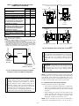
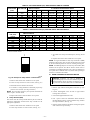
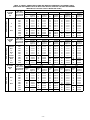
TABLE 8—AIR CONDITIONING (A/C) AIRFLOW SETUP SWITCH POSITION
AIR
CONDITIONER
(TONS)
Default
1-1/2
2
2-1/2
3
3-1/2
4
5
CFM AIRFLOW
1200 or
2000
600
800
1000
1200
1400
1600
2000
A/C SETUP
SWITCH POSITION
A/C-1 A/C-2 A/C-3
OFF
OFF
OFF
ON
OFF
ON
OFF
ON
OFF
ON
OFF
ON
ON
OFF
OFF
ON
ON
OFF
OFF
OFF
ON
ON
ON
ON
ALLOWABLE FURNACE MODEL SETUP
042040
3 Tons
1200 CFM
X
X
X
X
X
—
—
042060
3 Tons
1200 CFM
X
X
X
X
X
—
—
042080
3 Tons
1200 CFM
X
X
X
X
X
—
—
060080
5 Tons
2000 CFM
—
X
X
X
X
X
X
060100
5 Tons
2000 CFM
—
X
X
X
X
X
X
060120
5 Tons
2000 CFM
—
X
X
X
X
X
X
X—Indicates allowable selection.
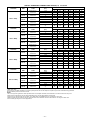
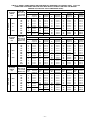
TABLE 9—CONTINUOUS FAN (CF) AIRFLOW SETUP SWITCH POSITION
CONTINUOUS
FAN (CFM)
Default
600
800
1000
1200
1400
1600
2000
CF SETUP
SWITCH POSITION
CF-1
CF-2
CF-3
OFF
OFF
OFF
ON
OFF
OFF
OFF
ON
OFF
ON
ON
OFF
OFF
OFF
ON
ON
OFF
ON
OFF
ON
ON
ON
ON
ON
ALLOWABLE FURNACE MODEL SETUP
042040
565*
X
X
X
X
X
—
—
042060
515*
X
X
X
X
X
—
—
042080
690*
X
X
X
X
X
—
—
060080
690*
—
X
X
X
X
X
X
060100
860*
—
X
X
X
X
X
X
060120
1035*
—
X
X
X
X
X
X
* Add 15% additional CFM when Bypass Humidifier switch SW-3 on control board is used.
X—Indicates allowable selection.
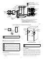
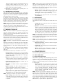
3. See Table 10 for setup switch description. (See Fig. 24 and
45.)
1
4. Replace main furnace door and blower access panel.
NOTE: If a bypass humidifier is used, setup switch SW-3 (BPH)
should be in ON position. This prevents nuisance limit trips caused
by the increased temperature in return air resulting from bypass.
NOTE: If modulating dampers are used, setup switch SW-5 (MZ)
should be in ON position. This allows furnace control center to
compensate for modulating dampers. The control re-calibrates for
new system static conditions once every minute while operating in
low-heat or continuous fan modes.
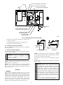
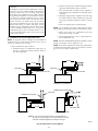
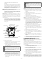
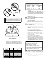
OFF
III.
PRIME CONDENSATE TRAP WITH WATER
A95198
Fig. 45—Example of Setup Switch in OFF Position
CAUTION: Condensate trap must be PRIMED or
proper draining may not occur. The condensate trap has 2
internal chambers which can ONLY be primed by pouring water into the inducer drain side of condensate trap.
1. Remove main furnace door and blower access panel.
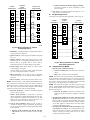
2. Locate CF setup switches on control center. (See Fig. 25.)
3. Determine desired continuous fan airflow.
4. Use Table 9 or wiring schematic to determine proper setup
position of CF switches. (See Fig. 24 and 45.)
NOTE: The CF switches are factory set to provide continuous fan
airflow equal to low-heat mode.
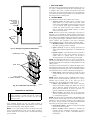
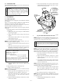
1. Remove upper inducer housing drain connection cap. (See
Fig. 46.)
2. Connect field-supplied 1/2-in. ID tube to upper inducer
housing drain connection.
5. Replace main furnace door and blower access panel.
3. Insert field-supplied funnel into tube.
C. Setup Switches (SW)
The control center has 8 setup switches that may be set to meet the
application requirements. Position these setup switches for the
appropriate requirement.
4. Pour 1 quart of water into funnel/tube. Water should run
through inducer housing, overfill condensate trap, and flow
into open field drain. (See Fig. 47.)
5. Remove funnel and tube from inducer housing and replace
drain connection cap and clamp.
1. Remove main furnace door and blower access panel.
2. Locate setup switches on control center. (See Fig. 25.)
—35—