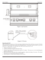
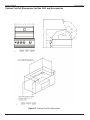
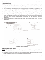
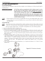
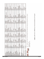
1
$5.00
2004 OWNER’S MANUAL
GRILLS
ISLANDS
CARTS
CONVECTION 3000 GRILL
Duplication without written consent is strictly prohibited.
This Owner’s Manual is for barbecues manufactured after January 1, 2004
Due to continuous improvement programs, all models, operation, and/or specifications are subject to change without prior notice.
LTR17006331
www.calspas.com
Owner’s Manual
Table of Contents
Table of Contents
Benefits of Owning a Cal Flame Barbecue ..........................................................................................2
Safety Instructions ................................................................................................................................3
Contact Information ..............................................................................................................................5
Warranty Information ............................................................................................................................5
Set-up and Delivery ..............................................................................................................................6
Grill Operation - Drop-In Grills............................................................................................................7
Grill Operation - Islands......................................................................................................................12
Grill Operation - Carts ........................................................................................................................21
Convection 3000 4-Burner Grill ........................................................................................................23
Grill Installation ..................................................................................................................................27
Installation of New Side Burner..........................................................................................................29
Installation of New Access Doors ......................................................................................................30
Sports Bar Canopy ..............................................................................................................................31
Liquid Propane (LP) Requirements ....................................................................................................36
Natural Gas (NG) Requirements ........................................................................................................38
Leak Testing Procedure ......................................................................................................................39
Cleaning and Maintenance Procedures ..............................................................................................40
Troubleshooting Procedures................................................................................................................42
Appendix ............................................................................................................................................44
Waterfall Operation ......................................................................................................................................44
Cal Flame Entertainment System ....................................................................................................45
Part Numbers....................................................................................................................................53
Lifetime Warranty ............................................................................................................................55
Cal Flame Program Charts ..............................................................................................................56
Notes ................................................................................................................................................58
Owner’s Manual
Page 1
Benefits
Owner’s Manual
BENEFITS OF OWNING A CAL FLAME BARBECUE
Owning a barbecue allows you to have a wonderful outdoor place to cook a nutritious family meal. It offers a
place for you to socialize with family and friends. A barbecue provides a great focal point in your backyard when
having parties, family get-together or just to hang out with your kids. Owning a barbecue can add character to
your patio and/or yard.
As with any new improvement to an existing area, precautions must be made before development can take place.
Throughout this manual, the owner will encounter 3 product lines - Barbecues, Firepits/fireplaces, and Carts.
Each product line will have similar lighting methods.
IT IS THE OWNERS RESPONSIBILITY TO ENSURE THAT AN EXISTING NATURAL GAS LINE
IS INSTALLED AND SAFE TO USE. CAL SPAS HIGHLY RECOMMENDS THAT THE OWNER
HAVE A LICENSED TECHNICIAN RUN ALL NATURAL GAS LINES AND CONNECT ALL
NATURAL GAS HOOK-UPS. CAL SPAS IN NO WAY WILL BE HELD RESPONSIBLE FOR AN
IMPROPERLY CONNECTED GAS LINE.
THE LIGHTING INSTRUCTIONS FOR THE ISLANDS AND CARTS IS IDENTICAL. PLEASE
FOLLOW THESE INSTRUCTIONS CAREFULLY, AS ANY DEVIATION MAY RESULT IN SERIOUS
INJURY, OR POSSIBLY DEATH.
Page 2
Owner’s Manual
Owner’s Manual
Safety Instructions
SAFETY INSTRUCTIONS
Please read before installing and operating your new Cal Flame grill.
1. Your new gas grill should be professionally installed by a licensed contractor. Refer to the instructions in this
manual to ensure proper and safe installation and operation.
2. IF YOU SMELL GAS:
A. Shut off gas to grill.
B. Extinguish any open flame.
C. Open lid.
D. If odor persists, immediately call your gas supplier or your fire department.
DO NOT TRY TO FIX THE PROBLEM YOURSELF..
3. CAUTION:
To prevent fire and smoke damage, remove all packaging material before operating grill.
4. Before you start cooking: Clean the grill thoroughly with hot, soapy water. This is necessary to remove
residuals and solvents, oil and grease which may have remained from the manufacturing process. The grates
should also be thoroughly cleaned in the same manner.
5. Spiders and other insects can nest in the burners of the grill and block the gas and airflow to the burner ports.
This creates a dangerous condition that can result in a fire from behind the valve panel. Inspect and clean the
burners periodically; follow guidelines in the Cleaning and Maintenance section of this manual.
6. In the event that a burner goes out and gas escapes, turn off the burner knobs, open the grill hood fully and
let it air-out. Do not attempt to use the grill or any other island feature until the gas has had time to dissipate.
7. Unless specifically recommended in this manual, do not repair or replace any part of the grill. A qualified
technician should perform all of the service. Any repairs made by a non- C.A.I. approved dealer technician
will void your warranty.
8. Never use the grill without the drip pan in place and pushed all the way to the rack located just under the
grill. Without it, hot grease could leak downward and produce a fire or explosion hazard.
9. Keep any electrical supply cord, or the rotisserie motor card away from the heated areas of the grill.
10. Never use the grill or side burner in windy conditions. If located in a consistently windy area (oceanfront,
mountaintop, etc.) a windbreak will be required. Always adhere to the specified clearances listed in this
manual.
11. The area surrounding your new grill should be kept clean, and free from flammable liquids and other
combustible materials such as mops, rags, brooms, as well as solvents, cleaning fluids, and gasoline.
12. Do not use the grill as a storage area for flammable or plastic items, which may ignite. Do not store any
materials inside or near BBQ island. Any LPG (Propane) cylinder not is use, should not be stored in the
vicinity of this or any other appliance.
13. Never line grill or side burners with tin foil.
14. When the unit is not in use, be sure to turn off the gas at the LPG tank.
15. Never locate this appliance in an enclosed room or under sealed overhead structure or any type of enclosed
area such as a garage, shed, or breezeway. Keep clear of trees and shrubs.
16. Do not place this grill under or near windows or vents that can be opened into your home.
Owner’s Manual
Page 3
Safety Instructions
Owner’s Manual
Precautions Regarding Children
1. Never leave children unattended in the area where the grill is being used.
2. Do not store items of interest to children around or below the grill or island.
3. Never allow children to sit or stand on any part of the grill or island.
Use Precautions
1. Never leave the grill and side burners unattended while using high flame settings. Boil-overs cause
smoking and greasy boil-overs may ignite.
2. Always use the proper size pan. Select utensils with flat bottoms large enough to cover the burner. The use
of under-sized utensils exposes the sides of the utensils to direct contact with a portion of the flame. This
can scorch utensils, and hamper cleanup. Excessive flames on large stainless steel pots can result in
permanent discoloration. For best results, we recommend commercial quality aluminum pans and utensils.
3. Always position handles of utensils inward, so they do not extend over adjacent work areas or cooking
areas. This reduces the risk of burns, ignition of flammable materials, and spillage due to accidental
contact with the utensils.
4. Do not use water on grease fires. Never pick up a flaming pan. Turn appliance off and smother the
flaming pan with a tight-fitting lid, cookie sheet or flat tray. For flaming grease outside of the pan,
smother with baking soda, or use a dry chemical or foam-type fire extinguisher.
5. Never let clothing, potholders or other flammable materials come in contact with or close to any grate,
burner or hot surface until it has cooled. Fabric may ignite and result in personal injury.
6. When using the grill, do not touch the grill rack, burner grate, or immediate surroundings, as these areas
become extremely hot and could cause burns.
7. Proper apparel is a safety consideration. Never wear loose fitting or hanging garments while using your new
grill.
8. Only use dry potholders - do not use a towel or other bulky cloth in place of potholders. Moist or damp
potholders used on hot surfaces could cause burns.
9. Do not heat any unopened glass or metal container of food on the grill. Pressure may build up and cause
the container to burst resulting in serious harm or damage to the grill.
10. Do not use charcoal in this grill or side burner.
11. Do not attempt to move stainless steel cart while hot or in use.
12. It is extremely important to lock all caster wheels even on flat even surfaces.
13. Do not lean, sit or stand on the stainless steel cart, including the foldout work surfaces.
14. Do not exceed 50 pounds of weight on the foldout work surfaces.
15. Do not block the vents located in the cabinet area of your Cal Flame Island and Stainless Steal Cart as gas
may build up incase of leak and cause serious damage.
16. Your grill must be plugged into a permanent, grounded 110 VAC outlet with a dedicated 15A GFCI
breaker. Do not use an extension cord to supply power to your Cal Flame Island, Grill or Cart. Such use
may result in fire, electrical shock or other personal injury. Do not install a fuse in the neutral or ground
circuit. A fuse in the neutral or ground circuit may result in an electrical shock hazard. Do not ground this
appliance to a gas supply pipe or hot water pipe. Keep any electrical supply cord and the fuel supply hose
away from any heated surfaces.
17. Do not reach over your grill or any other surfaces when hot or in use.
SAVE THIS MANUAL FOR FUTURE REFERENCE
Page 4
Owner’s Manual
Contact and Warranty Information
Owner’s Manual
CONTACT INFORMATION
For customer service, please contact your authorized dealer immediately. If you need additional information
and/or assistance, please contact:
C.A.I. Customer Service Department
1462 East Ninth Street
Pomona, CA
91766
Toll Free
1-800-CAL-SPAS
Fax
1-909-629-3890
WARRANTY INFORMATION
See your Cal Flame Barbecue dealer for a copy of the applicable warranty, details and any questions you may
have regarding the warranty coverage on your barbecue.
Warranty Limitations
The Limited Warranty is void if the barbecue has been subject to negligence, alteration, misuse, abuse, repairs
by non- C.A.I. authorized representatives, incorrect electrical installation, acts of God and any other cases
beyond the control of C.A.I. Examples of common acts invalidating this warranty include but are not limited to:
Scratches caused by normal use.
Damage caused by extreme weather conditions. (Hot, Cold, etc.)
Damage caused by dirt, sand, and/or water damage.
Damage caused by continued operation of the barbecue with either known or unknown problems.
Damage caused by direct sunlight.
Damage caused as a result of failure to follow the operating instructions as defined in this Owner’s Manual.
This Limited Warranty applies only to barbecues normally used for personal, family, or household purposes.
This Limited Warranty specifically excludes commercial barbecues.
Warranty Exclusions
C.A.I. warranties the barbecues from defects in material and workmanship for a period of one year from the
original date of purchase.
Barbecue stereo systems are delivered with their own manufacture warranty. For more information, please see
their warranties in the owner’s information package that was delivered with your barbecue for more information.
Locating Product Serial Number
BBQ Islands
Your new Cal Flame Island BBQ serial number is located on a metal plate inside the door below the grill on the
door. You will need this number to properly register your BBQ and activate coverage.
Please write this number in the space provided for future reference:
Serial Number:
Delivery Date:
REMINDER:
PLEASE DO NOT FORGET TO REGISTER YOUR NEW PRODUCT AT
WWW.CALSPAS.COM
Owner’s Manual
Page 5
Owner’s Manual
Delivery and Set-Up
DELIVERY AND SET-UP
Please make a record of the following. It will be valuable if service is required.
Barbecue Model:
Barbecue Serial Number:
Date Purchased:
Date Installed:
Barbecue Dealer’s Phone Number:
Barbecue Dealer’s Address:
Most cities and counties require permits for exterior construction and electrical circuits. In addition, some
communities have codes requiring residential barriers such as fencing and/or self-closing gates on property to
prevent unsupervised access to the property by children under the age of 5. Your dealer can provide information
on which permits may be required and how to obtain them prior to the delivery of your equipment.
PLANNING THE BEST LOCATION FOR YOUR BARBECUE
Safe and satisfactory operation of your new grill depends upon its proper installation. The installation,
adjustments and service of your new grill must be performed by C.A.I. qualified installers and service
technicians. This is necessary to ensure proper operation and also prevent accidents.
Location (Outdoor Use Only)
When planning your Cal Flame Island or cart location, be sure to consider the shortest gas line run possible. Also,
take into consideration the necessity of having a 100v power source. For use of your appliances (i.e. lights,
rotisserie, refrigerator, receptacles, etc.).
When determining a suitable location, take into account concerns such as exposure to wind, proximity to traffic
paths, and windows that open into the home. Keeping in mind natural gas line runs need to be as short as
possible. Locate the grill only in a well ventilated area.
Locate BBQ Islands grills and stainless steel carts in well ventilated areas, and only on solid, flat
foundations (i.e. cement slab or deck). Do not place BBQ Islands/ Outdoor Kitchens or stainless steel carts
on dirt or grass.
Built-In Installation
Your new grill is designed for easy installation into a non-combustible enclosure. The supporting deck and
counter must be level and flat. When determining the final location of your grill, it is required that ventilation be
provided in the enclosure so that gas will not become entrapped in the event of a leak. Make sure that you have
one vent placed at floor level and the other at 5” above floor level.
Built-In Design Models
If using a rear wall, locate a weather proof electrical outlet on the side of the grill that the rotisserie motor will
be located on. The rotisserie motor requires a 110/120v supply. The power supply cord on the motor is equipped
with a 3-prong (grounded) plug for protection against shock hazard. Do not cut or remove the grounding prong
from the plug.
Page 6
Owner’s Manual
Drop-In Grills
Owner’s Manual
GRILL OPERATION - DROP-IN GRILLS
Grilling
Grilling requires high heat for searing and proper browning. Most foods are cooked at the HI heat setting for
the entire cooking time. However, when grilling large pieces of meat or poultry, it may be necessary to turn the
heat to a lower setting after the initial browning. This cooks the food through without burning the outside. Foods
cooked for a long time or basted with a sugary marinade may need to lower heat setting near the end of the
cooking time. Warming rack is used for defrosting or for keeping food warm while grilling.
Grilling Hints
The cooking of meat, whether rare, medium, or well done, is affected to a large degree by the thickness of the
cut. Expert chefs say it is impossible to have a rare piece of meat with a thin cut.
The cooking time is affected by the kind of meat, also by the size and the shape of the cut, the temperature of
the meat when cooking begins, and the cooking degree desired.
When defrosting meats, it is recommended that it be done overnight in the refrigerator as opposed to a
microwave. This generally yields a juicier cut of meat.
Use a spatula instead of tongs or a fork to turn the meat. A spatula will not puncture the meat and let the juices
run out.
To get the juiciest meats, add seasoning or salt after the cooking is finished and turn the meat only once (juices
are lost when the meat is turned several times). Turn the meat just after the juices begin to bubble to the surface.
Trim any excess fat from the meat before cooking. To prevent steaks or chops from curling during cooking, slit
the fat around the edges at 2-inch intervals.
Do not leave the grill unattended while cooking.
Light (Illumination) Operation
Your Cal Flame Grill is equipped with either 1-halogen light (CR-3000) or 2-halogen lights (CR-4000 &
CR-5000). This feature is added for safety when cooking in non-illuminated areas. Also, for convenience when
cooking in poorly illuminated areas or simply for an inviting display of deliciously grilled food.
The On/Off switch controlling your halogen light(s) is located at the control panel on the front lower left side
(see Figure 25).
Your grill is equipped with a grounded (3 prong) 120 VAC plug located in the lower, left, rear corner of your
cart and must be plugged into a permanent, grounded 120 VAC outlet with a dedicated 15amp GFI breaker. DO
NOT cut or remove the ground prong as this may result in fire, electrical shock or other
personal injury. This electrical source provides power to the lights, refrigerator and rotisserie.
NOTE:
On units with the rotisserie option, an additional outlet will be needed to utilize the rotisserie
burner.
WARNING: Lock all casters on all cart wheels even when installed on flat level surfaces.
Owner’s Manual
Page 7
Owner’s Manual
Drop-In Grills
Figure 1. Light Operation
120VAC 3-Prong (grounded)
male plug. Plug male end into
the GFI outlet.
Figure 2. GFI Breaker.
Operating the Grill
Make sure all burner controls are off. Do not attempt to light the burners if the smell of gas is present. Check the
connection with a soap and water solution after attaching the hose. For LP units, make sure there is gas in the
tank and it is sitting upright. For natural gas units, make sure the shut off valve is on.
1. Make sure the drip tray is in place.
2. Light the grill burners using the instructions below.
3. Turn the control knob to HI and preheat the grill for 15 minutes. The top cover is to be closed during the
appliance preheat period.
4. Place the food on the grill and cook to desired completion. Adjust heat setting, if necessary. The control
knob may be set to any position between HI and LOW.
5. Allow the grill to cool and clean the drip tray after each use.
Page 8
Owner’s Manual
Drop-In Grills
Owner’s Manual
Lighting The Grill Burners
1. Open the hood.
2. Keep your face as far away from the burners as possible.
3. Rapidly rotate the burner knob counter clockwise past light position (You will hear a loud click) to high.
4. Listen for the "Whoosh" sound. If the burner does not light on the first try, repeat immediately.
5. If the burner does not light after three attempts, turn the control knobs to the OFF position. Wait 5 minutes
until the gas clears before attempting to light it again.
7. Repeat the procedure or try "Manual Lighting procedure" below.
8. Upon successful lighting, repeat the process on the other burners you wish to light.
9. To shut off burners rotate knob and turn to OFF. It is normal to hear a popping sound when the burners
returned off.
Manually Lighting The Grill Burners
1. Open the hood.
2. If you have just attempted to light the burner, allow 5 minutes for any accumulated gas to dissipate.
3. Slide out the drip tray from the grill.
4. Keep your face as far away from the burners as possible.
5. Using only a long stem match, hold near the burner ports.
6. Push in and turn counter clockwise the grills gas control knob just past the LIGHT position to HIGH.
7. Listen for the "Whoosh" sound. If the burner does not light after 5 seconds, turn the control knobs to the
OFF position. Wait 5 minutes until the gas clears before attempting to light it again.
8. If the burner does not light after several attempts see Troubleshooting Guide in the back of this manual.
Using Your Rotisserie
The rotisserie burner is an infrared type, which provides intense searing radiant heat. Preferred by professional
chefs over other methods, this intense heat is ideal for searing in the natural juices and nutrients found in quality cuts of meat.
Cooking with the Rotisserie
The rotisserie system is designed to cook items from the back using infrared heat. The location of the burner
allows the placement of a rotisserie-basting pan (included) beneath the food to collect juices and drippings for
basting and gravy. To flavor the contents of the basting pan, you can add herbs, onion, garlic, or spices.
Operating The Rotisserie
1. To load the rotisserie rod, hold the handle firmly while sliding one of the fork assemblies (prongs facing
away from the handle) onto the rod. Push the rod through the center of the food, then slide the other
holder (prongs toward the food) onto the rod. Center the meat on the rod and push the fork assemblies
firmly together. Tighten the thumbscrews. To secure any loose portions of your meat, use butcher string
(never use nylon or plastic string). Place basting pan under the food to collect the drippings.
2. To use the rotisserie, first mount the motor on the left side of the grill. Place securely onto support bracket.
3. The rod of the rotisserie system is assembled into the motor by placing the pointed end into the motor and
resting the threaded end on the support at the side of the grill. Once the rod is pushed as far as possible into
the motor, the grooved end of the rod should rest on the right side bracket.
4. If necessary, to offset unbalanced loads, slide the counter weight on to the rod. With the counter weight
loose, allow the loaded rod to rotate and come to a stop. Now rotate the counter weight above the rod in a
vertical position and tighten the thumbscrew. You can slide the counter weight away from or closer to the
rotisserie rod as needed for balanced operation. Once lit, the rotisserie burner will reach cooking
temperature in about 1 minute. The orange/red glow will even out in about 5 minutes.
Owner’s Manual
Page 9
Owner’s Manual
Drop-In Grills
Figure 3. Rotisserie Burner Assembly
Lighting The Infrared or Rotisserie Burner
1. Open the hood.
2. Push and hold the rotisserie burner knob in for about 5 seconds to allow gas into the the infrared burner, then
rotate knob rapidly counter clockwise past the light position (You will hear a loud click).
3. If the burner does not light on the first try, repeat immediately.
4. If the burner does not light within 5 seconds, turn the control knob to the OFF position. Wait 5 minutes until
the gas clears before attempting to light it again.
5. Repeat the procedure or try "Manual Lighting procedure" as shown below.
6. Upon successful lighting, repeat the process on any other available IR burner you may wish to light.
Manually Lighting The Infrared or Rotisserie Burner
1. Open the hood.
2. Push and hold the rotisserie burner knob in for about 5 seconds to allow gas into the the infrared burner, then
rotate knob rapidly counter clockwise past the light position (You will hear a loud click).
3. Hold a lit long stem match next to the burner ports.
4. If the burner does not light within 5 seconds, turn the control knob to the OFF position. Wait 5 minutes until
the gas clears before attempting to light it again.
5. If the burner does not light after several attempts see troubleshooting located in the back of this manual.
6. Upon successful lighting, repeat the process on any other available IR burner you may wish to light.
Figure 4. Rotisserie Burner Knob.
Page 10
Owner’s Manual
Drop-In Grills
Owner’s Manual
Cal Flame Familiarization
The following controls are for the Cal Flame Drop-In Grills, Stainless Steel Carts, Chef Series, Master Chef
Series & Gourmet Series Islands. Please familiarize yourself with these controls prior to operation of your Cal
Flame BBQ.
Figure 5. Grill Knob Operation
Owner’s Manual
Page 11
Owner’s Manual
Islands
GRILL OPERATION - ISLANDS
Grilling
Grilling requires high heat for searing and proper browning. Most foods are cooked at the HI heat setting for
the entire cooking time. However, when grilling large pieces of meat or poultry, it may be necessary to turn the
heat to a lower setting after the initial browning. This cooks the food through without burning the outside. Foods
cooked for a long time or basted with a sugary marinade may need to lower heat setting near the end of the
cooking time. Warming rack is used for defrosting or for keeping food warm while grilling.
Grilling Hints
The cooking of meat, whether rare, medium, or well done, is affected to a large degree by the thickness of the
cut. Expert chefs say it is impossible to have a rare piece of meat with a thin cut.
The cooking time is affected by the kind of meat, also by the size and the shape of the cut, the temperature of
the meat when cooking begins, and the cooking degree desired.
When defrosting meats, it is recommended that it be done overnight in the refrigerator as opposed to a
microwave. This generally yields a juicier cut of meat.
Use a spatula instead of tongs or a fork to turn the meat. A spatula will not puncture the meat and let the juices
run out.
To get the juiciest meats, add seasoning or salt after the cooking is finished and turn the meat only once (juices
are lost when the meat is turned several times). Turn the meat just after the juices begin to bubble to the
surface.
Trim any excess fat from the meat before cooking. To prevent steaks or chops from curling during cooking, slit
the fat around the edges at 2-inch intervals.
Do not leave the grill unattended while cooking.
Light (Illumination) Operation
Your Cal Flame Grill is equipped with either 1-halogen light (CR-3000) or 2-halogen lights (CR-4000 &
CR-5000). This feature is added for safety when cooking in non-illuminated areas. Also, for convenience when
cooking in poorly illuminated areas or simply for an inviting display of deliciously grilled food.
The On/Off switch controlling your halogen light(s) is located at the control panel on the front lower left side.
Your grill is equipped with a grounded (3 prong) 120 VAC plug located in the lower, left, rear corner of your
cart and must be plugged into a permanent, grounded 120 VAC outlet with a dedicated 15amp GFI breaker. DO
NOT cut or remove the ground prong as this may result in fire, electrical shock or other
personal injury. This electrical source provides power to the lights, refrigerator and rotisserie.
NOTE:
On units with the rotisserie option, an additional outlet will be needed to utilize the rotisserie
burner.
WARNING: Lock all casters on all cart wheels even when installed on flat level surfaces.
Operating the Grill
Make sure all burner controls are off. Do not attempt to light the burners if the smell of gas is present. Check
the connection with a soap and water solution after attaching the hose. For LP units, make sure there is gas in
the tank and it is sitting upright. For natural gas units, make sure the shut off valve is on.
Page 12
Owner’s Manual
Islands
Owner’s Manual
1. Make sure the drip tray is in place.
2. Light the grill burners using the instructions below.
3. Turn the control knob to HI and preheat the grill for 15 minutes. The top cover is to be closed during the
appliance preheat period.
4. Place the food on the grill and cook to desired completion. Adjust heat setting, if necessary. The control
knob may be set to any position between HI and LOW.
5. Allow the grill to cool and clean the drip tray after each use.
Lighting The Grill Burners
1. Open the hood.
2. Keep your face as far away from the burners as possible.
3. Rapidly rotate the burner knob counter clockwise past light position (You will hear a loud click) to high.
4. Listen for the "Whoosh" sound. If the burner does not light on the first try, repeat immediately.
5. If the burner does not light after three attempts, turn the control knobs to the OFF position. Wait 5 minutes
until the gas clears before attempting to light it again.
7. Repeat the procedure or try "Manual Lighting procedure" below.
8. Upon successful lighting, repeat the process on the other burners you wish to light.
9. To shut off burners rotate knob and turn to OFF. It is normal to hear a popping sound when the burners
returned off.
Manually Lighting The Grill Burners
1. Open the hood.
2. If you have just attempted to light the burner, allow 5 minutes for any accumulated gas to dissipate.
3. Slide out the drip tray from the grill.
4. Keep your face as far away from the burners as possible.
5. Using only a long stem match, hold near the burner ports.
6. Push in and turn counter clockwise the grills gas control knob just past the LIGHT position to HIGH.
7. Listen for the "Whoosh" sound. If the burner does not light after 5 seconds, turn the control knobs to the
OFF position. Wait 5 minutes until the gas clears before attempting to light it again.
8. If the burner does not light after several attempts see Troubleshooting Guide in the back of this manual.
Using Your Rotisserie
The rotisserie burner is an infrared type, which provides intense searing radiant heat. Preferred by professional
chefs over other methods, this intense heat is ideal for searing in the natural juices and nutrients found in
quality cuts of meat.
Cooking with the Rotisserie
The rotisserie system is designed to cook items from the back using infrared heat. The location of the burner
allows the placement of a rotisserie-basting pan (included) beneath the food to collect juices and drippings for
basting and gravy. To flavor the contents of the basting pan, you can add herbs, onion, garlic, or spices.
Operating The Rotisserie
1. To load the rotisserie rod, hold the handle firmly while sliding one of the fork assemblies (prongs facing
away from the handle) onto the rod. Push the rod through the center of the food, then slide the other
holder (prongs toward the food) onto the rod. Center the meat on the rod and push the fork assemblies
firmly together. Tighten the thumbscrews. To secure any loose portions of your meat, use butcher string
(never use nylon or plastic string). Place basting pan under the food to collect the drippings. Tighten the
thumbscrew. You can slide the counter weight away from or closer to the rotisserie rod as needed for
balanced operation.
Owner’s Manual
Page 13
Owner’s Manual
Islands
2. To use the rotisserie, first mount the motor on the left side of the grill. Place securely onto support bracket.
3. The rod of the rotisserie system is assembled into the motor by placing the pointed end into the motor and
resting the threaded end on the support at the side of the grill. Once the rod is pushed as far as possible into
the motor, the grooved end of the rod should rest on the right side bracket.
4. If necessary, to offset unbalanced loads, slide the counter weight on to the rod. With the counter weight
loose, allow the loaded rod to rotate and come to a stop. Now rotate the counter weight above the rod in a
vertical position and tighten the Light rotisserie burners following instructions on page 22. Once lit, the
rotisserie burner will reach cooking temperature in about 1 minute. The orange/red glow will even out in
about 5 minutes.
Lighting The Infrared or Rotisserie Burner
1. Open the hood.
2. Push and hold the rotisserie burner knob in for about 5 seconds to allow gas into the the infrared burner, then
rotate knob rapidly counter clockwise past the light position (You will hear a loud click).
3. If the burner does not light on the first try, repeat immediately.
4. If the burner does not light within 5 seconds, turn the control knob to the OFF position. Wait 5 minutes until
the gas clears before attempting to light it again.
5. Repeat the procedure or try "Manual Lighting procedure" as shown below.
6. Upon successful lighting, repeat the process on any other available IR burner you may wish to light.
Manually Lighting The Infrared or Rotisserie Burner
1. Open the hood.
2. Push and hold the rotisserie burner knob in for about 5 seconds to allow gas into the the infrared burner, then
rotate knob rapidly counter clockwise past the light position (You will hear a loud click).
3. Hold a lit long stem match next to the burner ports.
4. If the burner does not light within 5 seconds, turn the control knob to the OFF position. Wait 5 minutes until
the gas clears before attempting to light it again.
5. If the burner does not light after several attempts see troubleshooting located in the back of this manual.
6. Upon successful lighting, repeat the process on any other available IR burner you may wish to light.
Page 14
Owner’s Manual
Islands
Owner’s Manual
Figure 6. C-100
Figure 7. C-100B
Figure 8. C-200
Owner’s Manual
Page 15
Owner’s Manual
Islands
Figure 10. C-250
Figure 9. C-225
Figure 11. C-250B
Page 16
Figure 12. C-300L
Owner’s Manual
Islands
Owner’s Manual
Figure 13. C-300R
Figure 14. C-400L
Figure 15. C-400R
Figure 16. MC-500
Owner’s Manual
Page 17
Owner’s Manual
Islands
Figure 17. MC-600
Figure 18. MC-700
Figure 19. G-1000
Page 18
Owner’s Manual
Islands
Owner’s Manual
Figure 20. G-2000
Figure 21. G-2500
Figure 22. G-2500-F
Owner’s Manual
Page 19
Owner’s Manual
Islands
Figure 23. G-3000
Figure 24. G-3000 Sports Bar
Figure 25. G-3500F
Page 20
Owner’s Manual
Owner’s Manual
Carts
GRILL OPERATION - CARTS
Grilling
Grilling requires high heat for searing and proper browning. Most foods are cooked at the HI heat setting for
the entire cooking time. However, when grilling large pieces of meat or poultry, it may be necessary to turn the
heat to a lower setting after the initial browning. This cooks the food through without burning the outside. Foods
cooked for a long time or basted with a sugary marinade may need to lower heat setting near the end of the
cooking time. Warming rack is used for defrosting or for keeping food warm while grilling.
Grilling Hints
The cooking of meat, whether rare, medium, or well done, is affected to a large degree by the thickness of the
cut. Expert chefs say it is impossible to have a rare piece of meat with a thin cut.
The cooking time is affected by the kind of meat, also by the size and the shape of the cut, the temperature of
the meat when cooking begins, and the cooking degree desired.
When defrosting meats, it is recommended that it be done overnight in the refrigerator as opposed to a
microwave. This generally yields a juicier cut of meat.
Use a spatula instead of tongs or a fork to turn the meat. A spatula will not puncture the meat and let the juices
run out.
To get the juiciest meats, add seasoning or salt after the cooking is finished and turn the meat only once (juices
are lost when the meat is turned several times). Turn the meat just after the juices begin to bubble to the surface.
Trim any excess fat from the meat before cooking. To prevent steaks or chops from curling during cooking, slit
the fat around the edges at 2-inch intervals.
Do not leave the grill unattended while cooking.
Light (Illumination) Operation
Your Cal Flame Grill is equipped with either 1-halogen light (CR-3000) or 2-halogen lights (CR-4000 &
CR-5000). This feature is added for safety when cooking in non-illuminated areas. Also, for convenience when
cooking in poorly illuminated areas or simply for an inviting display of deliciously grilled food.
The On/Off switch controlling your halogen light(s) is located at the control panel on the front lower left side.
Your grill is equipped with a grounded (3 prong) 120 VAC plug located in the lower, left, rear corner of your
cart and must be plugged into a permanent, grounded 120 VAC outlet with a dedicated 15amp GFI breaker. DO
NOT cut or remove the ground prong as this may result in fire, electrical shock or other
personal injury. This electrical source provides power to the lights, refrigerator and rotisserie.
NOTE:
On units with the rotisserie option, an additional outlet will be needed to utilize the rotisserie
burner.
WARNING: Lock all casters on all cart wheels even when installed on flat level surfaces.
Owner’s Manual
Page 21
Carts
Owner’s Manual
Operating the Grill
Make sure all burner controls are off. Do not attempt to light the burners if the smell of gas is present. Check
the connection with a soap and water solution after attaching the hose. For LP units, make sure there is gas in
the tank and it is sitting upright. For natural gas units, make sure the shut off valve is on.
1. Make sure the drip tray is in place.
2. Light the grill burners using the instructions below.
3. Turn the control knob to HI and preheat the grill for 15 minutes. The top cover is to be closed during the
appliance preheat period.
4. Place the food on the grill and cook to desired completion. Adjust heat setting, if necessary. The control
knob may be set to any position between HI and LOW.
5. Allow the grill to cool and clean the drip tray after each use.
Figure 27. 4-Burner Cart
Figure 26. 3-Burner Cart
Figure 28. 5-Burner Cart
Page 22
Owner’s Manual
Owner’s Manual
Convection 3000 Grill
CONVECTION 3000 4-BURNER GRILL
Outdoor barbecue grills have become increasingly popular for the summertime cooking of meats and
vegetables. Traditionally, barbecue grills have been heated by charcoal briquettes, but a new generation of
barbecue grills are heated by gas fired burners.
Many modern barbecue grills have a closeable hood or other structure which can be used to provide an enclosed
heating compartment. Such heating compartments can be used like the oven on a stove to slow roast various
items of food, such as large pieces of meat.
A problem with present-day barbecue grills is that the heat within the cooking compartment is non-uniform. The
heat in the central portion of the cooking department tends to be much more intense than the heat in the
side portions of the cooking compartment. This leads to uneven cooking within the cooking compartment and
makes use of the outdoor grill somewhat haphazard.
Accordingly, there is need for a barbecue grill which overcomes this problem in the prior art.
Grill Operation - Convection 3000 Grill
Grilling
Grilling requires high heat for searing and proper browning. Most foods are cooked at the HI heat setting for
the entire cooking time. However, when grilling large pieces of meat or poultry, it may be necessary to turn the
heat to a lower setting after the initial browning. This cooks the food through without burning the outside. Foods
cooked for a long time or basted with a sugary marinade may need to lower heat setting near the end of the
cooking time. Warming rack is used for defrosting or for keeping food warm while grilling.
Grilling Hints
The cooking of meat, whether rare, medium, or well done, is affected to a large degree by the thickness of the
cut. Expert chefs say it is impossible to have a rare piece of meat with a thin cut.
The cooking time is affected by the kind of meat, also by the size and the shape of the cut, the temperature of
the meat when cooking begins, and the cooking degree desired.
When defrosting meats, it is recommended that it be done overnight in the refrigerator as opposed to a
microwave. This generally yields a juicier cut of meat.
Use a spatula instead of tongs or a fork to turn the meat. A spatula will not puncture the meat and let the juices
run out.
To get the juiciest meats, add seasoning or salt after the cooking is finished and turn the meat only once (juices
are lost when the meat is turned several times). Turn the meat just after the juices begin to bubble to the surface.
Trim any excess fat from the meat before cooking. To prevent steaks or chops from curling during cooking, slit
the fat around the edges at 2-inch intervals.
Do not leave the grill unattended while cooking.
Light (Illumination) Operation
Your Cal Flame Grill is equipped with either 1-halogen light (CR-3000) or 2-halogen lights (CR-4000 &
CR-5000). This feature is added for safety when cooking in non-illuminated areas. Also, for convenience when
cooking in poorly illuminated areas or simply for an inviting display of deliciously grilled food.
The On/Off switch controlling your halogen light(s) is located at the control panel on the front lower left side.
WARNING: Lock all casters on all cart wheels even when installed on flat level surfaces.
Owner’s Manual
Page 23
Convection 3000 Grill
Owner’s Manual
Your grill is equipped with a grounded (3 prong) 120 VAC plug located in the lower, left, rear corner of your
cart and must be plugged into a permanent, grounded 120 VAC outlet with a dedicated 15amp GFI breaker. DO
NOT cut or remove the ground prong as this may result in fire, electrical shock or other
personal injury. This electrical source provides power to the lights, refrigerator and rotisserie.
NOTE:
On units with the rotisserie option, an additional outlet will be needed to utilize the rotisserie
burner.
Figure 29. Convection 3000 Grill
Page 24
Owner’s Manual
Owner’s Manual
Convection 3000 Grill
Figure 30. Intake and Exhaust Designs
Owner’s Manual
Page 25
Convection 3000 Grill
Owner’s Manual
Cooking with the Convection 3000 Grill
Use a meat thermometer and take the guesswork out of cooking meat and seafood. The fan must be turned on
in order for the Convection 3000 Grill to cook the items that are listed below.
IMPORTANT:
After desired cooking temperature is reached, remove meat from heat source and let it stand
10 to 15 minutes before carving. The amount of time required for resting varies with the
size of the cuts of your meat. During this resting time, the meat continues to cook (meat
temperature will rise 5˚ to 20˚ after it is removed from the heat source.
Roasts, Steaks and Chops
Rare
Medium Rare
Medium
Medium Well
Well Done
Poultry
Turkey
Stuffing
165˚ to 170˚
165˚ to 170˚
165˚
Sausage
Ham
Raw
Pre-Cooked
Fish
Tune and Shark
Shrimp
Lobster
Scallops
Clams
Muscles
Oysters
Item
Steak
Steak
Cake
Pizza
Cookies
Page 26
120˚ to 125˚
130˚ to 135˚
140˚ to 145˚
150˚ to 155˚
160˚ to 165˚
160˚
Center is bright red, pinkish toward the exterior portion
Center is very pink, slightly brown toward the exterior
Center is light pink, outer portion is brown
Not pink
Steak is uniformly brown throughout
Poultry
Cook until juices run clear
Cook until juices run clear; legs move easily
Pork
Cook until no longer pink
160˚
140˚
140˚
125˚
Weight/size
2”THK/ 3 lbs.
1”THK/ 1.5 lbs.
12” Round
1 lb
Seafood
Flesh is opaque; flakes easily
Cook until medium rare (do not over cook)
Meat turns red and opaque in center when cut
Meat turns red and opaque in center when cut
Milky white or opaque, and firm
Cook until shells crack open (if shell doesn’t open, throw away)
Cook until shells crack open (if shell doesn’t open, throw away)
Cook until shells crack open (if shell doesn’t open, throw away)
CONVECTION GRILL COOKING MATRIX
Temperature Cook Time
3Burner
420˚
40 minutes
(3) Low
390˚
20 minutes
(3) Low
350˚
19 minutes
(2) Low
400˚
20 minutes
(3) Low
350˚
10 minutes
(2) Low
4Burner
(4) Low
(4) Low
(3) Low
(4) Low
(3) Low
5Burner
(5) Low
(4) Low
(3) Low
(4) Low
(4) Low
Owner’s Manual
Grill Installation
Owner’s Manual
GRILL INSTALLATION
Safe and satisfactory operation of your new grill depends upon its proper installation. The installation,
adjustments and service of your new grill must be performed by C.A.I. qualified installers and service
technicians. This is necessary to ensure proper operation and also prevent accidents.
Location (Outdoor Use Only)
When planning your Cal Flame Island or cart location, be sure to consider the shortest gas line run possible.
Also, take into consideration the necessity of having a 110 volts power source. For use of your appliances (i.e.
lights, rotisserie, refrigerator, receptacles, etc.).
When determining a suitable location, take into account concerns such as exposure to wind, proximity to traffic
paths, and windows that open into the home. Keeping in mind natural gas line runs need to be as short as
possible. Locate the grill only in a well ventilated area
Locate BBQ Islands grills and stainless steel carts in well ventilated areas, and only on solid, flat foundations
(i.e. cement slab or deck). Do NOT place BBQ Islands / Outdoor Kitchens or stainless steel carts on dirt or grass.
Built-in Installation
Your new grill is designed for easy installation into a non-combustible enclosure. The supporting deck and
counter must be level and flat. When determining the final location of your grill, it is required that ventilation be
provided in the enclosure so that gas will not become entrapped in the event of a leak. Make sure that you have
one vent placed at floor level and the other at 5 inches above floor level.
Built-in Design Models
If using a rear wall, locate a weatherproof electrical outlet on the side of the grill that the rotisserie motor will
be located on. The rotisserie motor requires a 110/120-volt supply. The power supply cord on the motor is
equipped with a 3-prong (grounded) plug for protection against shock hazard. Do not cut or remove the
grounding prong from the plug.
Figure 31. Rotisserie and Accessory Outlet Location
Owner’s Manual
Page 27
Owner’s Manual
Grill Installation
Cabinet Cut-Out Dimensions for Gas Grill and Accessories
Figure 32. Cabinet Cut-Out Dimensions
Page 28
Owner’s Manual
Installation of Nw Side Burner
Owner’s Manual
INSTALLATION OF NEW SIDE BURNER
1. Install side burner into an area of 17-1/2 inches long, 11 inches wide and 3 inches deep.
2. Assemble a 3/8 pipe nipple to the 3/8 pipe tee using teflon tape or pipe sealant. Use only sealant that is
approved for use on LP gas.
3. Install the pipe tee assembly to the grill intake pipe with pipe sealant. Tighten assembly and align the branch
opening of the tee with the hole of the cabinet.
4. Connect the flexible hose (male end) to the pipe tee with pipe sealant.
5. Install and secure the side burner into the island by simply setting in place.
6. Connect the female end of the flexible hose to the side burner intake pipe with pipe sealant.
7. Connect gas supply to the grill.
8. Check for gas leaks using soap water solution. (1 part liquid soap, 3 parts water).
Figure 33. Side Burner Installation
Owner’s Manual
Page 29
Owner’s Manual
Installation of New Access Doors
INSTALLATION OF NEW ACCESS DOORS
Installing Access Doors
1. Provide cut out and door jamb with inside dimensions as follows:
16 1/4" X 19 “ for single door
28 1/4” x 19 3/8” for double door
2. Secure the steel frame with 16 screws of type #10 x fl” truss head phillips S/S.
3. Attach doors to frame.
4. Adjust doors as follows:
a) For height adjustment, loosen the two screws attached to each mounting plate.
b) Snap off hinge and secure mounting plate with #6 X 1” flat phillips S/S.
c) For side adjustment turn screw to increase or decrease door overlay.
d) For depth adjustment, loosen screw, adjust door to desired position and retighten screw.
Figure 34. Access Door Installation
Page 30
Owner’s Manual
Sports Bar Canopy
Owner’s Manual
SPORTS BAR CANOPY
While the G3000 Island / Sports Bar Canopy is intended for outdoor use, some precautions must be taken
when using and caring for your new Cal Flame equipment. When the equipment is not being used, or
especially in times of inclement weather, it is the owners responsibility to remove and store the electronic
equipment that is listed in this manual. When storing the equipment, it is strongly advised that the
equipment be stored in a dry and moisture-free environment. The electronic equipment that is used with
the G3000 Island/Sports Bar is high-end audio and video equipment, therefore making them extremely
susceptible to moisture damage. It is the owners responsibility to ensure that the G3000 Island/Sports Bar
be covered with a water-resistant tarp or plastic sheeting to protect the enclosure.
Any damage incurred from moisture is not covered by the warranty. These preventative care measures
must become a part of the owner’s maintenance routine. In addition, all efforts should be taken by the
owner to keep excessive dirt and foreign debris from settling into the island enclosure. If these
requirements are neglected, all warranties on the audio and video components will be void. With a little
care and maintenance, you can look forward to many trouble-free years of use.
G3000 ISLAND/SPORTS BAR CANOPY WIRING
Prior to assembling the bar and the canopy, the owner must wire the unit. The wiring plan has been designed
with simplicity in mind. Electrical service for this unit requires 120 V/20 AMP circuit breaker for correct
operation. If there are any questions dealing with the wire code, please refer to Figure 35. All wiring must be
ran before the final assembly of the barbecue and before the initial assembly of the canopy.
Figure 35. Wiring Instructions
Owner’s Manual
Page 31
Owner’s Manual
NOTE:
Sports Bar Canopy
The following sections show how each wiring connection is to be made. These
connections will be identical for the top and bottom of the canopy support post.
Make sure that after the connections are made, the cables are tucked gently into
each end of the canopy support posts. DO NOT let the canopy support posts and
canopy support post mounts pinch the cables. If this happens, the cables will be cut
and have to be replaced.
Audio/ Video (A/V) Cables
There will be two connection points for the A/V cables: one at the top of the canopy support post
and one at the bottom of the canopy support post. These cables will be stuffed into each end of the
canopy support post.
NOTE:
1. The A/V cables are what control the television. They are marked: yellow for video, red for right audio, and
white for left audio. The A/V cables will be ran from the television up through the junction box (located on
top of the canopy).
2. The A/V cables coming from the television will then be plugged into a set of longer cables (color match the
cables: red to red, white to white and yellow to yellow).
3. Each set of A/V cables will then be feed down (inside) the outside canopy support posts of the canopy .
NOTE:
Be sure that each cable is securely attached. If not, the quality of the picture and volume will be
affected.
Lights
NOTE:
The 3-position (male) connector has 3 metal prongs at the end of it. These prongs fit into the female
receptacle of the other connector.
1. Match up the 3-position wire (female) with the 3-position wire (male) and securely attach them together.
This step must be repeated for each main support post.
Antenna
NOTE:
The G3000 Island/ Sports Bar should already be wired. If not, please refer to the G3000
Island/ Sports Bar Owner’s Manual.
1. Match up the coaxial end (female) with the other coaxial end (male) and securely attach them together. Run
the single antenna coaxial cable into the 3-way splitter (located under the grill of the G3000 Island/ Sports
Bar itself).
Page 32
Owner’s Manual
Sports Bar Canopy
Owner’s Manual
Canopy Assembly
The following instructions will allow you to assembly the canopy section of the G3000 Island/ Sports Canopy.
NOTE:
The following sections show how each wiring connection is to be made. These
connections will be identical for the top and bottom of the canopy support post.
Make sure that after the connections are made, the cables are tucked gently into
each end of the canopy support posts. DO NOT let the canopy support posts and
canopy support post mounts pinch the cables. If this happens, the cables will be cut
and have to be replaced.
Figure 36. Canopy Assembly
1. Lay the two triangle-shaped canopy pieces on a flat and level surface, with the support sleeves
facing up.
2. Place the “U” channel in between the two triangle-shaped end pieces with the “U” channel facing inward.
Line up the holes and bolt into place (Figure 36A and 36B). Repeat this step for the opposite end of the “U”
channel.
3. Repeat this process with all three support “U” channels. Make sure that all three “U” channels are facing
inward.
4. After making all the wire connections, slide each canopy support post into the support sleeves (located on
the canopy). Gently tuck the cables into the support post, making sure not to pinch the cables (Figure 37).
Owner’s Manual
Page 33
Owner’s Manual
Sports Bar Canopy
Figure 37. Canopy Assembly
Mounting the G3000 Island/ Sports Bar Canopy
CAUTION:
THE FOLLOWING STEP IS A 2-PERSON PROCEDURE. THE CANOPY, AT THIS STAGE,
IS EXTREMELY HEAVY. IT IS RECOMMENDED THAT THE OWNER USE A HELPER.
1. Carefully rotate the canopy upright and place it as close as possible to the canopy mounting holes.
2. Finish connecting all the wires. When complete, stuff the excess wire down into the canopy mounting
holes (Figure 38A).
3. Use care placing the canopy support posts into the canopy mounting holes, as you DO NOT want to pinch
the wires.
4. Place the provided screens on top of the canopy, in the specified locations (Figure 38B).
Figure 38. Canopy Final Installation
Page 34
Owner’s Manual
Sports Bar Canopy
Owner’s Manual
Awning Installation
With the canopy installation nearly complete, the awning must be installed and wired. It should be noted that all
screws that are used for the installation of the awning are self-tapping sheet metal screws. No drilling should be
necessary.
1. Line up the holes for the awning bracket with the corresponding pre-drilled holes on the awning. Use two
carriage bolts for the upper two holes and a flat-head Phillips for the single lower hole. Tighten until snug,
but don’t over-tighten (Figure 39A).
2. After mounting the awning bracket, remove the awning from the box. Tilt the awning at a 45˚ angle and hang
the awning onto the awning bracket (Figure 39B).
3. After making sure that the awning is securely hung onto the awning bracket, tilt the awning up to a 45˚ angle
(again) and connect the two electrical leads (male) securely to the two electrical leads (female, attached to
the awning). When complete, carefully tuck the wires into the hole and gently lower the awning
(Figure 39C).
4. Place set-screws through the awning bracket and awning into the canopy frame. Do not over-tighten
(Figure 39D).
Figure 39. Awning Installation
Awning Open/ Close Switch
NOTE:
The 2-position (male) connector has 2 metal prongs at the end of it. These prongs fit into the female
receptacle of the other connector.
1. Match up the 2-position wire (female) with the 2-position wire (male) and securely attach them together
(Figure 39 - Insert). This step must be repeated for each main support post.
Owner’s Manual
Page 35
LP Gas Requirements
Owner’s Manual
LP GAS REQUIREMENTS
LP Gas Requirements
Always check the rating plate to make sure the gas supply you are hooking up to is the gas type the grill is
manufactured for.
IMPORTANT WARNING:
NOTE:
All Cal Flame grills are manufactured with the highest regard to safety.
For this reason, Cal Flame grills are either manufactured to operate on
Liquid Propane (LP) or Natural Gas (NG) and cannot be converted. To
verify the grills operating fuel, remove the bottom drip pan and check
serial number label on the left. Either LP or NG will be marked on the
operating tab, indicating the proper operating fuel. Attempting to convert
Cal Flame grills from one fuel to another may result in serious injury and
void the warranty coverage.
Please note that if you do not have an updated filler valve on your existing propane tank, you will
need to purchase one at your local hardware store, as you will not be allowed to refill the tank at
any filling station.
LP Gas Hook Up
NOTE:
An enclosure for an LP gas cylinder shall be vented by openings at the level of the cylinder valve and
at floor level. The effectiveness of the opening(s) for purposes of ventilation shall be determined with
the LP-gas supply cylinder in place. This shall be accomplished in one of the following manners:
1. One side of the enclosure shall be completely open.
2. Enclosures that have four sides, complete with a top and bottom:
a. At least two ventilation openings at cylinder valve level shall be provided in the sidewall, equally sized,
spaced at 180˚ (3.14 rad), and unobstructed. Each opening shall have a total free area of not less than fi”
square inch per pound (7.1 cm≈/kg) of stored fuel capacity, and not less than a total free area of 10 square
inches (64.5 cm≈).
b. Ventilation opening(s) shall be provided at floor level and shall have a total free area of not less than fi
square inch per pound (7.1 cm≈/kg) of stored fuel capacity and not less than a total free area of 10 square
inches (64.5cm≈). If ventilation openings at floor level are in a sidewall, there shall be at least two
openings. The bottom of the openings shall be at floor level and the upper edge no more than 5 inches
(127 mm) above the floor. The openings shall be equally sized, spaced at 180˚ (3.14 rad) and
unobstructed.
c. Every opening shall have minimum dimensions so as to permit the entrance of a 1/8 inch (3.2 mm)
diameter rod.
Figure 40. LP Attachment Assembly
Page 36
Owner’s Manual
Owner’s Manual
LP Gas Requirements
LP Gas Manifold Pressure
For plumbed-in LP installation, use a convertible regulator and set it for LP gas.
LP Gas Supply Pressure
LP Gas Supply Pressure
Maximum line pressure for plumbed-in propane is 14” W.C psi (3.5 kPa). Minimum line pressure for propane
is 11” W.C.
LP Gas Pressure Regulator
The unit must be used with the gas pressure regulator. The regulator will control and maintain a uniform gas
pressure in the manifold. The burner orifices have been sized for the gas pressure delivered by the regulator.
LPG Cylinder Specification
Any LP gas supply cylinder used with this grill must be approximately 12 inches in diameter and 18 inches high.
The maximum fuel capacity is 20 lbs. of propane, or 5 gallons. Full cylinder weight should be approximately
38 lbs. (43.7 lbs. nominal water capacity.) Always use the cylinder dust cap on the cylinder valve outlet during
transport and when the cylinder is not connected to the grill.
Transporting the LP Gas Supply Cylinder
Only one cylinder should be transported at a time. Transport cylinder in an upright and secure manner with
control valve turned off and the dust cap in place.
Owner’s Manual
Page 37
Natural Gas Requirements
Owner’s Manual
NATURAL GAS REQUIREMENTS
Natural Gas Requirements
Always check the rating plate to make sure the gas supply you are hooking up to is the gas type the grill is
manufactured for.
IMPORTANT WARNING:
All Cal Flame grills are manufactured with the highest regard to
safety. For this reason, Cal Flame grills are either manufactured to
operate on Liquid Propane (LP) or Natural Gas (NG) and
cannot be converted. To verify the grills operating fuel, remove the
bottom drip pan and check serial number label on the left. Either LP
or NG will be marked on the operating tab, indicating the proper
operating fuel.
Attempting to convert Cal Flame grills from one fuel to another may
result in serious injury and void the warranty coverage.
IMPORTANT:
Never connect the grill to an unregulated gas supply.
The installation of this appliance must conform with local codes or, in the absence of local codes, to the
national fuel gas code, ANSI Z223.1a-1998. Installation in Canada must be in accordance with the standard
CAN/CGA-B149.2, Propane Installation Code.
NATURAL Gas Connection: (Must be performed by a licensed contractor or local gas company representative).
Ensure that the service supplying the grill is fitted with a shut off valve conveniently positioned to the grill and
giving ease of access.
Your Cal Flame Grill for use with Natural Gas comes equipped with its own regulator which MUST NOT be
removed. If, this regulator needs to be replaced use only the type specified by Cal Flame for this appliance.
1. Remove the rear panel from the BBQ to gain access to the regulator and gas connection point.
2. Connect a suitable flex connector to the grill regulator.
Page 38
Owner’s Manual
Owner’s Manual
Leak Testing Procedure
LEAK TESTING PROCEDURE
Leak Testing
Perform a leak test at least once each year whether the gas supply cylinder has been disconnected or not. In
addition, anytime the gas cylinder is connected to the regulator or any part of the gas system is disconnected or
replaced, conduct a leak test.
As a safety precaution, remember to always leak test your grill outdoors in a well-ventilated area. Never smoke
or permit sources of ignition in the area while doing a leak test. Do not use a flame, such as a lighted match to
test for leaks. Use only a leak testing solution as specified below.
Leak Testing Procedure
1.
2.
3.
4.
5.
6.
Prepare a leak testing solution of sudsy water by mixing in a spray bottle half-liquid soap and half water.
Check and make sure all the control knobs are in the OFF position.
Turn cylinder valve knob counter clockwise one turn to open.
Apply leak-testing solution by spraying on joints of the gas delivery system.
Blowing bubbles in the soap solution indicates that a leak is present.
Stop a leak by tightening the loose joint or by replacing the faulty part with a replacement part
recommended by the manufacturer. Do not attempt to repair the cylinder valve if it should become
damaged. The cylinder must be replaced.
7. If you are unable to stop a leak, shut off the gas supply at the cylinder valve. Remove the cylinder from
the grill. Call an authorized gas appliance service technician or LP gas dealer. Do not use the appliance until
the leak is corrected.
8. Push in and turn any control knob to release pressure in the hose and manifold.
9. Turn off the control knob.
Owner’s Manual
Page 39
Cleaning and Maintenance
Owner’s Manual
CLEANING AND MAINTENANCE
As with any piece of fine equipment, your new grill must be kept clean and properly maintained to maximize its
performance and longevity. Cleaning internal parts of the grill regularly as determined by the amount of use and
foods cooked. The entire grill should be cleaned at least once a year. To assure safe and proper maintenance, we
recommend you follow these directions carefully.
IMPORTANT:
DISCONNECT ELECTRICAL SUPPLY BEFORE CLEANING ANY PART OF THE
GRILL.
Cleaning the Grill Racks
The easy way to clean the grill racks is to scrub them immediately after you have finished cooking and turned off
the flame. Wear a grill mitt to protect your hand from the heat and steam. Dip a brass bristle barbecue brush in
water and scrub the hot grill. Dip the brush frequently to increase the amount of steam. Steam is created as water
contacts with the hot grill, assists in the cleaning process by softening food particles. The food particles will fall
onto the briquette tray and burn or fall into the drip tray. If the grill is allowed to cool before cleaning, the removal
of those residual particles from food will be more difficult.
If desired, when completely cool, remove the grill racks for thorough cleaning. Use soap and water for this
cleaning. Specks or grease can either gather on the surface of the stainless steel and bake onto the surface rack and
give the appearance of rust. For removal, use an abrasive pad (like Scotch Brite) in conjunction with a
stainless steel cleaner. This needs to be done in extreme cases only, or before storing the grill for on extended period
Cleaning the Warming Rack
The warming rack can be cleaned using the same procedure as Cleaning the Grill Racks.
Cleaning the Drip Pan
The full width drip pan will collect grease from the main grill area. The pan should be cleaned after every use to
avoid the possibility of a grease fire. Be sure to allow the drip pan to cool prior to cleaning. You may clean the
drip pan with a solution of warm soapy water. Make sure to rinse thoroughly to avoid staining.
Care of Stainless Steel Carts & Grills
Stainless steel is a highly preferred material in the residential and commercial industries due to its strength,
ability to resist corrosion and its ease of cleaning. Stainless steel is often taken for granted and assumed to be
indestructible. However, care must be taken to ensure long life in your Stainless Steel Cal Flame Grills and Carts.
To maintain the original appearance of your Cal Flame grill and/or cart, a regular routine must be
followed.
DO NOT:
Use wire wool pads, scrappers, harsh abrasive, scoring materials, bleaches, or harsh cleaners on your Cal Flame
Stainless Steel cart and/or grill, or allow salt and vinegar mixtures to remain in contact for a long period of time.
This will cause scratching, scoring, rusting and pitting of your product.
Your Cal Flame BBQ grill is made of #304 stainless steel. This represents that this component is of non-rusting
and non-magnetic stainless steel. There are many types of stainless steel cleaners on the market today. We
recommend that you clean the external and internal stainless steel components with a cleaner that is approved for
#304 stainless steel and only clean when the grill is cool and in indirect light.
Never use steel wool to clean your grill and never clean the grill when it is hot. Be especially careful when
cleaning the Highlighted (shinny) areas or your grill. Only clean these areas when absolutely necessary.
Page 40
Owner’s Manual
Owners Manual
Cleaning and Maintenance
Covering Your Stainless Steel Cart
When not in use and after cooling, cover your Cal Flame Stainless Steel cart with our full length, zippered side
canvas cover. The cover will help protect your cart from detrimental effects of weather & environmental
pollutants (please see your local Cal Flame dealer for details).
After Use Care
1. The easiest way to clean the grill is immediately after cooking is completed and after turning off the flame.
Wear a barbecue mitt to protect your hand from the heat and the steam. Dip a brass bristle barbecue brush
in hot soapy water and scrub the hot grill rack. The steam from the water coming in contact with the hot
rack will assist in the cleaning process by softening any food, dirt or grease stuck to the racks.
2. Wipe the grill with a damp soapy cloth and rinse with warm/hot, clean water.
3. For more tenacious deposits, including oil, grease and water-borne deposits, use a multipurpose cream
cleanser and apply with a soft, damp cloth. Rinsing with warm/hot, fresh, clean water.
4. Dry with a soft, dry, clean towel if preferred.
Cleaning the Island Cabinets
Be sure to unplug the electrical supply before cleaning any part of your Cal Flame BBQ. Spray cabinet area with
a soap and water solution. Rinse with a gentle stream of fresh water.
Cleaning the Burners
IMPORTANT: All of the gas control knobs must be turned to the off position and the fuel should be off and
fuel line disconnected prior to starting this procedure.
To reduce the risk of flashback, this procedure should be followed at least once a month or when your grill has
not been used for an extended period of time.
1. Remove burners from grill by carefully lifting each burner up and away from the gas valve orifice.
2. Wire brush outer surface of burner to remove food residue and dirt. Clean any clogged ports with a stiff
wire such as an opened paper clip.
3. Inspect the burner for damage (cracks and holes). If any damage is found, replace burner and discontinue
grill usage.
4. Upon reinstallation, inspect the following: gas valve orifices for cleanliness and condition; the location of
the ignitors.
Owner’s Manual
Page 41
Troubleshooting Procedures
Owner’s Manual
TROUBLESHOOTING PROCEDURES
If Grill Fails to Operate Properly:
1. Turn off gas at source, turn the Control Knobs to the ‘OFF’ position and wait 5 minutes before trying again.
2. Check gas supply at a connections.
3. Repeat lighting procedure and if grill still fails to operate properly, turn off gas at source, turn the control
knobs to the off position and wait for the grill to cool down and check the following:
Problem:
Solution:
Misalignment of burner tube(s) over orifice(s)
Reposition the burner tube to properly seat over orifice.
Figure 41. Burner Tube Reposition
Problem:
Solution:
Obstruction In Gas Line
Remove fuel line from grill. Do not smoke or perform any maintenance in the vicinity of an open
flame. Open gas valve for one second to blow out any debris. Close off gas valve and reconnect
fuel line securely.
Problem:
Solution:
Plugged Orifice
Remove cooking grills, Flame Tamer and grease tray. Remove burners from bottom of firebox
by pulling cotter pin from beneath burner peg using a standard screwdriver or needle nose
pliers. Carefully lift each burner up and away from the gas orifice. Remove the orifice from the
control valve. Gently clear any obstruction with a fine wire. Reinstall orifice, reinstall burners
over orifices and seat burner peg into position hole at the bottom ledge of the firebox. Replace
cotter pins. Replace cooking components and grease collectors. If an obstruction is suspected in
the control valve, please contact your local Cal Flame dealer for assistance.
Page 42
Owner’s Manual
Owner’s Manual
Problem:
Solution:
Troubleshooting Procedures
Misalignment of Ignitor on Burner
Check for proper position of electrode tip. The tip of the electrode should be pointing forward
towards the front of the burner and should be free of grease to allow proper sparking. The
ignition wire should be connected firmly to the valve ignition device and electrode. Replace the
ignition wire if it is frayed or cracked. With gas supply closed and all control knobs set to the off
position, check each position ignitor individually for presence of spark at electrode. In turn, push
each knob in fully and rotate about 1/4 turn to the left (counter-clockwise) until you hear a loud
click. The trigger hitting the strike block should produce a blue spark at the electrode tip. Return
control knob to the off position before checking the next ignitor.
While the grill is still hot, you must wait for a minimum of five minutes before commencing
re-ignition (this allows accumulated gas fumes to clear). If all checks/ corrections have been made
and gas grill fails to operate properly, contact your local Cal Flame dealer.
Problem:
Solution:
Yellow Flame
Once the entire burner is operating, check the flame color to be sure that flame color is mostly
blue. Some yellow at the tips may be present due to impurities in the fuel.
If the flame is golden or yellow in color, the reason could be seasoning salts, oil film, or other
foreign matter on the burner.
Problem:
Solution:
Flashback
When fire occurs in and around the burner tubes, immediately turn off gas at its source and turn
the control knob(s) clockwise to the ‘OFF’ position. Wait until the grill has cooled off and then
clean the burner tubes and burners as described on page of this manual.
Owner’s Manual
Page 43
Owner’s Manual
Appendix
APPENDIX
The items that will be covered in this section will consist of the following:
Waterfall Operation
Cal Flame Entertainment System
Part Numbers
Lifetime Warranty
Cal Flame Programs
Notes
In order for your retailer to expedite your order, for parts and accessories, it is recommended that you have the
information that you attained in the Set-Up and Delivery section. Customer Service will want all this
information for warranty purposes.
WATERFALL OPERATION (Optional)
The following models come with the waterfall option: MC-700, G-2000, G-2500, G-2500F and G-3000. To turn
the waterfall on, the unit must be plugged in. To turn the waterfall off, the unit must be unplugged.
NOTE:
Make sure that there is no debris in the filler pan for the waterfall. The pump will recirculate water
up through the fireplace and then filter down the sides and front. It is also important that the owner
maintains a consistent water level, as “dry” pumping will burn out the pump motor.
Figure 42. Waterfalls
Page 44
Owner’s Manual
Owner’s Manual
Cal Flame Entertainment System
CAL FLAME ENTERTAINMENT SYSTEM
Splash Stereo System
Figure 43. Cal Flame Entertainment System
This system can be used to listen to AM or FM Stereo signals, CD’s and also audio from the optional DVD and
TV Tuner on our Entertainment Cal Flame unit.
Each Cal Flame unit that is equipped with the Splash Stereo system is delivered with the manufacturers
operating instructions. We strongly recommend that you read these instructions prior to operating this unit.
NOTE:
Although this unit is marine grade, you will still need to protect it from water and the elements.
• Do not place wet CD’s into this unit at any time.
• Always close the CD protection door.
Remember, water damage is not covered by the warranty.
Entertainment Systems
Cal Flame units equipped with the TV / DVD systems use this Splash stereo to broadcast the TV or DVD audio
signals.
Set Up:
1. Program preset station #1 to 88.7FM to receive the audio signal that the TV and DVD systems are
transmitting on.
2. Set Base to +3. (As described in the stereos operating manual.)
3. Set Treble to +4. (As described in the stereos operating manual.)
4. Do Not Use the Z music enhance feature of the Splash Stereo System.
5. Set the volume between 15 and 28 .
If the Cal Flame unit should loose power for any reason, it will be necessary to reset these settings.
NOTE:
Owner’s Manual
Page 45
Cal Flame Entertainment System
Owner’s Manual
17” TV Monitor Operation: (Optional)
Turning On the TV Monitor:
Once the TV has been opened (either by manual or automatic operation) you will be able to operate the TV
with the silver TV remote control.
Front Panel Features (Figure 43)
1. Power Button - Bright red when system is ON, dim when system is OFF.
2. Volume Up/Down - Controls volume to external speakers, if connected. Also, used to adjust picture
control setting when “contrast”, “bright”, “sharpness”, color” or “tint” is displayed on the screen.
3. TV/AV - Any video equipment connected to the AUDIO/VIDEO inputs can be used with the TV by
pressing this button. Each time the button is pressed the Audio/Video source will change in the following
sequence: TV, AV1, AV2, and AUX.
4. Sensor Eye - Allows the remote control to operate the LCM1502TV’s OSD system (On Screen Display),
volume Wired Headphone Jacks (and optional external speakers), and for control of Video Media Player
connected through a source component harness.
5. Three Position Dome Light Switch Auto - Automatically switched on the dome lights in conjunction with the vehicle’s interior illumination.
Off - The dome lights will not turn on in this position.
On - Turns on the dome lights.
6. Screen Release - Slides in the direction of the arrow to release the drop down screen.
NOTE: For safety, hand hold the screen before you slide the screen release to drop down screen.
7. Menu Button - Gives you access to the OSD Main Menu.
8. Channel Up/Down - Changes the TV channel.
9. ENTER Button - Use this button to end the choice on the menu.
10. Dome Lights - Provides additional information.
Figure 44. Television Layout
Page 46
Owner’s Manual
Owner’s Manual
Cal Flame Entertainment System
Remote Control Operation (Figure 44)
1. TV Controls:
a. TV Power
Press this button to turn on the set.
Press the button again to turn the set off.
2. Direct Access (0-9, 1--) Number Buttons
Use these buttons to select a channel. The channel number chosen will be displayed on the screen for about
four seconds. To select channels 0-99, press two numbers. For example, to select channel 8, press 0,8. To
select above 100, press the 1-button, then the number buttons for the last two digits of the channel. For
example, to select channel 115, press 1--, 1,5.
3. CHANNEL Up and Down
Use these buttons to select pre-programmed channels of two select channels up or down.
4. VOLUME Up and Down
Use these buttons to raise or lower the volume level of the Wired Headphones or External Speakers if
installed. They are also used to make adjustments in the picture mode.
NOTE: These buttons will not affect the volume of wireless headphones or a wired RF modulator. When
using these devices, the volume must be adjusted with the headphone volume control or with
your radios volume control.
5. MENU Button
Press the MENU button. The MENU display appears. Use the Channel Up and Down buttons to select the
desired function, then press ENTER button to end the choice.
6. TV/VIDEO Button
Press this button to access the AUDIO/VIDEO input jacks, on the front and rear of the TV. As the button is
pressed, the on-screen display will cycle as follows:
7. MUTE Button
Press this button to turn the TV sound off. Press again to restore sound to the previously set level. MUTE
may also be released by pressing the VOLUME +/-.
8 When tuned to a channel press this button to store or erase the channel from memory. The stored channel
numbers are displayed in GREEN on the screen and the no stored channel numbers are in RED.
9. AUTO PROGRAM Button
Select the regular channel broadcast TV or CABLE TV for AUTO PROGRAM. All the channel numbers for
TV or CABLE TV will be scanned. The broadcasting signals will be detected and automatically stored.
10. ENTER Button
Use this button to end the choice on the menu.
11. PICTURE SELECT Button
Each time this button is pressed the on-screen picture adjustment display cycles through “adjustment
screens” as follows:
Owner’s Manual
Page 47
Cal Flame Entertainment System
Owner’s Manual
Figure 45. Remote Control
Page 48
Owner’s Manual
Owner’s Manual
Cal Flame Entertainment System
VCR Controls
12. VCR POWER Button
This button is used to turn the unit on and off.
13. “REW” REWIND Button
If this button is pushed while the tape is stopped, the tape will rewind. If this button is pushed while the tape
is playing, the VCR will go into rewind search mode. For more information on search feature of the VCR,
consult VCR Owner’s Manual.
14. PLAY Button
Press this button to activate play mode while a tape is loaded into the VCR. This button may also be used
to disengage search and pause modes. For more information, consult the VCR Owner’s Manual.
15. “F.FWD” FAST FORWARD Button
If this button is pushed while the tape is stopped, tape will fast forward. If this button is pushed while the
tape is playing, the VCR will go into fast forward search mode. For more information on search feature of
the VCR, consult the VCR Owner’s Manual.
16. STOP Button
Press this button to stop the video tape.
17. REPLAY Button
Press this button will rewind the video tape and immediately begin playback when the video tape is fully
rewound.
Operation
1. Point the remote control directly at the TV Monitor.
2. Press the Red Power Button located at the top left side of the remote control.
3. Allow a few seconds for the TV monitor to warm up before pressing any other buttons.
4. Once on, the TV monitor will display a small icon at the lower left side signifying which mode the TV is
currently in.
5. Press the “SELECT” button located at the top right side of the TV remote control until the icon
“COMPOSITE VIDEO” is displayed on the screen of the TV monitor. This will allow the TV Monitor to
accept the signal from the DVD player.
6. When an antenna, cable or satellite system is connected to the coaxial cable on the right front side of the
spa, you will be able to receive live TV signals by pressing the “SELECT” button until the
“COMPOSITE TV” icon appears on the TV monitor. Allow a few second for the TV tuner to acquire the
new signal prior to switching channels.
7. Press the right “VOL” button to adjust the volume up to “80” as displayed on the screen. This will allow
the Stereo system to receive enough volume to reproduce the audio signal without distortion.
NOTE:
You will not be able to hear audio form the TV Monitor itself. All audio signals for the TV or DVD
are only acquired through the stereo when programmed to 88.7FM.
Adjusting the Picture
When watching the TV programs, the quality of the picture can be adjusted to suit your taste.
1. Press MENU. The main menu appears.
2. Press SELECT VIDEO. The video source appears. Press this button to access the AUDIO/VIDEO input
jacks.
3. Select CLOSED CAPTION and then press ENTER.
Closed captioning lets you display the audio portion of a program as text on the TV screen. This is useful
to the hearing impaired or anyone who wants to watch a program without a sound.
Owner’s Manual
Page 49
Cal Flame Entertainment System
Owner’s Manual
There are two types of closed captioning available: C1 (Caption 1)and C2 (Caption 2). C1 displays the full
translation of the primary language in your area. C2 may be used as a source for secondary languages,
simplified English, or other translations transmitted in your area.
Closed captioning is not available on all channels or at all times. Only specific programs are encoded with
closed captioning information.
4. Press either CHANNEL up or down to select the function. Make sure the highlight bar is SET PICTURE
and then press ENTER.
5. Select the item to adjust. For example:
To adjust brightness, press CHANNEL up or down buttons to select BRIGHTNESS and press ENTER.
6. Adjust the level by pressing VOLUME.
7. To adjust other items, repeat all of the above.
NOTE: The menu or display disappears from the screen if you do not press + or - within a few seconds.
Whenever a menu or display disappears from the screen, and + or - buttons on the front of the
TV become the volume adjustment buttons. If you want to adjust the picture only, you can use
the remote control by simply pressing the PICTURE SELECT.
Description of Adjustment Items
ADJUSTMENT
ITEM
Press VOLUME Down
Press VOLUME Up
CONTRAST
Decrease picture contrast
for soft color
Increase picture contrast
for vivid color
BRIGHTNESS
Darken the picture
Brighten the picture
SHARPNESS
Decrease picture sharpness
Increase picture sharpness
TINT
Decrease Tint
Increase Tint
COLOR
Decrease color intensity
Increase color intensity
To restore the factory settings
Select the item of picture while the main menu is displayed. Then select the item of RESET. All the picture
functions (CONTRAST, BRIGHTNESS, SHARPNESS, TINT, COLOR) will go back to the factory settings.
8. Press either CHANNEL up or down to select the function. Make sure the highlight bar is AUTO
PROGRAM and then press ENTER.
9. Press CHANNEL either up or down to select the function. Make sure the highlight bar is ANTENNA
INPUT and then press ENTER.
Remote Infrared Sensor/Repeater
The LCM1502TV incorporates a Infrared Sensor which relays the signals from the remote control to allow the
LCM1502TV to be controlled simply by pointing it’s remote control at the remote sensor. This provides control of the auxiliary equipment such as a Flex vision VCR or DVD Player. The Remote Infrared Sensor can relay
signals from most manufacturers Remote Control to its respective component connected to the Video 1 and 2
inputs. In this case you must use the Remote Control supplied with the other manufacturers component.
Page 50
Owner’s Manual
Owner’s Manual
Cal Flame Entertainment System
Cal Flame Entertainment System Operation
DVD Player and Surround Sound Processor (Optional)
This system contains the DVD player and DVD remote controller.
NOTE:
Although encased in a plastic housing with weather seals, this system and remote control are not
waterproof. You must be take every step necessary to keep this system dry. Water damage is not
covered by the manufacturers warranty.
These instructions are to describe basic functions. Please see the DVD manufacturers operating instructions for
other features and functions. These instructions are delivered with the Cal Flame owners manual in a clear
plastic bag inside the stainless steel cabinet
Operation
1. Press the POWER button on the DVD unit or remote control to turn the system on. A “Welcome DVD
Video” banner will be displayed across the screen.
2. Press POWER on the Stereo / Cd player
3. Move the DVD selector switch (Located next to the DVD player) to the ON position.
This will allow the Audio signal to be received by the Stereo / CD player
NOTE: When not using the DVD player the Audio selector switch must be in the of position to receive
regular AM an FM broadcasts.
4. Tune the Stereo / Cd player to 88.7 FM to receive the audio signal.
5. Press the OPEN button on the DVD player and insert a DVD.
CAUTION: DO NOT INSERT WET DVD’S.
6. Press either the ENTER button on the DVD player or the Play button on the remote control to start the DVD
IMPORTANT:
Recommended stereo settings are BASS +3, TREBLE +4 and stereo volume not to
exceed 28. Exceeding these setting or using the Z -enhanced feature on the stereo will
cause the system to distort and damage speakers.
Figure 46. Cal Flame Entertainment DVD Player.
WARNING:
Owner’s Manual
DVD System and remote control are NOT waterproof or water-resistant. Water damage is not
covered by the manufacturers warranty. Please make sure that hands and DVD’s are dry before
coming in contact with this or any electronic option.
Page 51
Owner’s Manual
Accessories
Operating the DVD System In TV Mode:
Figure 47. DVD Player
The DVD system is used to feed the audio signal from the TV Tuner to the stereo. You will need to switch the
audio and Video modes with DVD remote to properly receive picture and sound.
NOTE: The Stereo must be tuned to 88.7FM to receive audio signals from either the DVD or TV Tuner.
Instructions:
1.
2.
3.
4.
Turn on DVD system as mentioned on the previous pages.
Press the SELECT button on the TV Remote Control to switch Video to COMPOSITE TV.
Press the A/V button on the DVD Remote Control to switch the Video from OUT to IN.
Press the Channel Up or Down buttons on the TV remote control to select TV Channel.
Switching Back to DVD Operation:
1. Press the SELECT button on the TV Remote Control to switch Video to COMPOSITE VIDEO.
2. Press the A/V button on the DVD Remote Control to switch the Video from IN to OUT.
3. Press the PLAY on the DVD remote Control.
WARNING: DVD System, Tuner System and their remote control’s are NOT waterproof or water-resistant.
Water damage is not covered by the manufacturers warranty. Please make sure that hands and
DVD’s are dry before coming in contact with this or any electronic option.
Page 52
Owner’s Manual
Owner’s Manual
Parts List
PARTS LIST
Contact your local Cal Flame Dealer to place your parts and accessories order. Or fax this completed form to (909) 9475087 with Credit Card Information: Visa
Master Card
American Express
________________________
Expiration Date______________ Card Number __ __ __ __ __ __ __ __ __ __ __ __ __ __ __ __
Home Address:_____________________________________City______________________State_____Zip_________
Print Name_____________________________________ Signature______________________________________
Daytime Phone Number_(_____)__________ Evening Phone Number _(_____)___________________ DO NOT SEND
CASH or CHECK
Please allow 2-3 weeks to receive your order. Prices and Specifications are subject to change without notice. For more
products and information please visit us on our web site at www.calspas.com. Shipping, handling and customs fees are
the responsibility of the purchaser.
DESCRIPTION
GRILLS
2 Burner Grill, NG/LP
3 Burner Grill w/Lights, Back Burner, NG/LP
4 Burner Convection Oven w/Lights,
Back Burner, NG/LP
5 Burner Grill w/Lights, Back Burner, NG/LP
PART NUMBER
QUANTITY
BBQ04000431
BBQ04000404
1
1
BBQ04000417
BBQ04000424
1
1
CR2010
CR3010
CR4010
1
1
1
CR4010C
1
CARTS
2 Burner Cart, NG/LP
3 Burner Cart w/Lights, Back Burner, NG/LP
4 Burner Cart w/Lights, Back Burner, NG/LP
4 Burner Cart Convection w/Lights,
Back Burner, NG/LP
3 Burner Cart w/Single Side Burner, w/Lights
Back Burner, NG/LP
4 Burner Cart w/Single Side Burner
4 Burner Cart Convection w/Lights, Back Burner,
NG/LP, w/ Single Side Burner
5 Burner Cart w/Double Side Burner
CR3010S
CR4010S
1
1
CR4010CS
CR5010S2
1
1
SIDE BURNERS
Deluxe Single Side Burner, NG/LP
Deluxe Double Side Burner, NG/LP
BBQ041100644
BBQ041100645
1
1
BBQ04100091
BBQ858
BBQ843P
BBQ04101028
1
1
1
1
BBQ04100679
BBQ04100681
BBQ04100682
BBQ04100683
BBQ04100771
BBQ04100659
1
1
1
1
1
1
BBQ04100656
BBQ04100657
BBQ04100658
1
1
1
BBQ85-2P
BBQ852-1P
1
1
ACCESSORIES
Cutting Board w/ Drawer & Knife Set
Foot Rest
Beer Tap
Cal Flame Control Knob
BBQ Umbrella
Cream
Green
Burgundy
Black
Umbrella Flange
Cal Flame BBQ Grates
Warming Rack
3 Burner
4 Burner
5 Burner
Single Side Burner
Liquid Propane
Natural Gas
Owner’s Manual
Page 53
Parts List
Owner’s Manual
DESCRIPTION
PART NUMBER
Cal Flame Thermometer
Brass Burner
Smoke Tray
Deluxe Single Side Burner
Liquid Propane
Natural Gas
Deluxe Double Side Burner
Liquid Propane
Natural Gas
Cocktail Center (Buitl-In)
18”
30”
Infrared 3 & 4 Burner
Rotisserie Burner
3 Burner
4 Burner
5 Burner
Stainless Steel Storage Drawers (20.5x13x20.5)
3 Drawer
2 Drawer
BBQ Tote w/Apron, Mitt, S.S., Cleaner, Utensils
BBQ Flame Timers
16 1/2” Propane/ Trash Drawer
Deluxe Glass Door
30” Stainless Steel Double Door
18” Stainless Steel Single Door
Stainless Steel Sink w/Faucet
Juice Bar
18”
30”
Drip Tray Handle w/out Tray
3 Burner
4 Burner
5 Burner
Drip Tray w/out Handle
3 Burner
4 Burner
5 Burner
BBQ04100375
BBQ04100661
BBQ854P
1
1
1
BBQ898P
BBQ898-1P
1
1
BBQ899P
BBQ899-1P
1
1
BBQ842-18
BBQ842-30
BBQ04300430
1
1
1
BBQ856P3
BBQ856P4
BBQ856P5
1
1
1
BBQ841P
BBQ840P
BBQ04100095
BBQ04103010
BBQ857P
BBQ848P
BBQ839P-30
BBQ839P-18
BBQ845P
1
1
1
1
1
1
1
1
1
BBQ846P-18
BBQ846P-30
1
1
BBQ04103030
BBQ04103031
BBQ04103032
1
1
1
BBQ04103020
BBQ04103021
BBQ04103022
1
1
1
COVERS FOR CAL FLAME DROP-INS
3 Burner
4 Burner
5 Burner
BBQ010
BBQ011
BBQ012
1
1
1
COVERS FOR CAL FLAME CARTS
3 Burner
4 Burner
5 Burner
BBQ835CR5
BBQ835CR4
BBQ835CR5
1
1
1
COVERS FOR CAL FLAME ISLANDS
Chef Series
C-100
C-200
C-225 w/ Backsplash
C-250
BBQ835C1
BBQ835C2
BBQ835C225-B
BBQ835C25-B
1
1
1
1
Page 54
QUANTITY
Owner’s Manual
Owner’s Manuals
Parts List
DESCRIPTION
PART NUMBER
Chef Series (Cont.)
C300 (Left w/Backsplash)
C300 (Right w/Backsplash)
C400 (Left w/Backsplash)
C400 (Right w/Backsplash)
BBQ835C3-LB
BBQ835C3-RB
BBQ835C4-LB
BBQ835C4-RB
1
1
1
1
Gourmet Series
G1000
G2000
G2500
G2500 w/ Fireplace
G3000
G3500
G3500 w/ Fireplace
BBQ835G1
BBQ835G2-B
BBQ835G25
BBQ835G25-F
BBQ835G3
BBQ835G35
BBQ835G35-F
1
1
1
1
1
1
1
Master Chef Series
MC500
MC600
MC700
BBQ835MC5
BBQ835MC6
BBQ835MC7
1
1
1
Owner’s Manual
QUANTITY
Page 55
WARRANTY
Limited Warranty
Lifetime: Equipment Warranty
Lifetime: Component Warranty
Cal Flame Barbecue Line: C.A.I. warranties the stainless steel
& brass burners, stainless steel & cast iron cooking grills
against deterioration and corrosion due to defects in materials
and workmanship for the lifetime of the aforementioned
product.
Cal Flame Barbecue Line: C.A.I. warranties the stainless steel
grill body, grill lid, heavy duty stainless steel rotisserie,
Stainless steel mountings, for the lifetime of the
aforementioned product.
Lifetime: Structural Frame Warranty
1 Year equipment and component warranty
Cal Flame Barbecue Line: C.A.I. warranties the Structural
Frame to maintain its structural integrity for the lifetime of the
aforementioned product. This warranty excludes carts which
have a one year warranty and is guaranteed to be free from
defect in materials and workmanship at time of delivery.
Cal Flame Barbecue Line: C.A.I. warranties the rotisserie motor,
non stainless steel fastener, temperature gauge and plastic items
such as knobs, trays, etc. to be free from defects in material and
workmanship for a period of one year. Fading is specifically
excluded from this warranty.
1 Year Component Warranty
Cal Flame Barbecue Line: C.A.I. warranties the Stainless steel
storage door, drawers, sink and warming rack against
deterioration of the aforementioned product.
C.A.I. guarantees the decorative finishes such as stucco, grout, brick, rock, and tile to be free from defects in material and workmanship at time of
delivery.
Manufacture Warranty
All barbecue units/carts are manufactured with the highest quality appliances and are guaranteed to be free from defect of material and
workmanship at time of delivery. The appliance warranty is extended through the manufacturer of the product. These items include but are not limited
to the following: Stereos, speakers, refrigerators, keg refrigerator, and accessories.
Extent of Warranty This 2004 Cal Flame Warranty is only valid on the Cal Flame Barbecue Line delivered in the continental United States and
Canada, and extends through the selling dealer to the original purchaser at the original site of installation. This warranty becomes valid at time of
purchase and ends either by specified time-frame listed above, owner transfer, or relocation.
Warranty Performance In the event of a malfunction or defect covered under the terms of this warranty, the factory authorized selling dealer is
responsible for performing all necessary repairs. To obtain service, contact the authorized selling dealer. In the event the consumer is unable to obtain
satisfactory customer service from the authorized selling dealer, written notification must be given to the C.A.I. Customer Relations Department within
(10) ten days of the reported failure. There will be no charge for parts on a covered item. However, the authorized service agent may assess labor, freight
and a reasonable travel or mileage charge per service call. If C.A.I. determines that repair of a covered item is not feasible, C.A.I. reserves the right to
replace the defective merchandise with merchandise equal in value to the original purchase price. In the event of any warranty replacement, all removal,
replacement, installation and shipping costs are the responsibility of the barbecue owner. This warranty is non-transferable and may not be extended
beyond the above mentioned time frames what-so-ever by any of C.A.I.’s representatives.
Warranty Limitations and Exclusions This warranty is void if the barbecue unit/cart has been subject to negligence, alteration, misuse, abuse,
repairs, incorrect and/or prohibited applications, dings, dents and scratches. Gas lines must be installed by a licensed plumber only or local gas co.),
incorrect electrical installation (licensed electrician only is acceptable). Serviced by non- C.A.I. authorized representatives, acts of God and any other
cases beyond the control of C.A.I. Please refer to the owner’s manuals for examples of exclusions and of common acts invalidating this guarantee This
limited warranty applies only to barbecue units used for personal, family, and outdoor household purposes.
Disclaimers C.A.I. shall not be liable for loss of use of the barbecue unit or other incidental or consequential costs, expense or damages, which may
include but are not limited to removal of permanent deck or other custom fixtures or the necessity for crane removal. Any implied warranty shall have
duration equal to the duration of the applicable warranty stated above. Under no circumstances shall C.A.I. or any of its representatives be held liable
for injury to any person or damage to any property, however arising.
Legal Remedies This Limited Warranty gives you specific legal rights and you may have other rights, which may vary from state to state.
Customer Service For customer service, contact the authorized selling dealer immediately. If you need additional information or assistance, please
contact the C.A.I Customer Relations Department at 1462 East Ninth Street • Pomona, CA 91766, or call 909-623-8781
This Limited Warranty is effective for BBQ’s manufactured after January 01, 2004
Owner’s Manual
Page 55
Page 56
Owner’s Manual
Owner’s Manual
Page 57
Notes
Owner’s Manual
NOTES
Page 58
Owner’s Manual