1
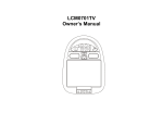
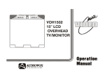
LCM1502TV
Owner’s Manual
Audiovox Specialized Applications, LLC
www.asaelectronics.com
US PATENT # D467, 234
Important Notice
Television Reception
It is unlawful in most jurisdictions for a person to drive a
motor vehicle which is equipped with a television viewer
or screen that is located in the motor vehicle at any point
forward of the back of the driver’s seat, or that is visible,
directly or indirectly, to the driver while operating the
vehicle. In the interest of safety, the LCM1502TV should
never be installed where it will be visible, directly or
indirectly, by the operator of the motor vehicle.
This entertainment system is designed primarily for
viewing pre-recorded movies or playing video games.
Television reception in a moving vehicle will be limited
and in some areas will not be possible due to weak and
variable signal strength.
Television viewing in a
stationary vehicle will result in an improvement, but may
still be marginal due to strength. The quality of the
picture will not be consistent with home TV reception.
Reception may be affected by the weather and distance
from the TV station. A weak signal may cause the
picture to roll, be snowy, or cause some color loss.
Please note that the state of Rhode Island forbids the
Installation of such a device in a motor vehicle.
-1-
FEATURES
Congratulations on your purchase of the Flexvision
LCM1502TV drop down TV/Video Monitor.
The
LCM1502TV has been designed to give you and your
family many years of video entertainment in the mobile
environment. Please read the directions that follow to
familiarize yourself with the product and to ensure that
you obtain the best results from your equipment.
NOTE: Installation options vary. See the individual
Owner’s Manuals for each component in your system to
obtain a full understanding of each component’s
operation.
• 15” TFT (Thin Film Transistor) Active Matrix LCD
(Liquid Crystal Display) Monitor
• OSD (On Screen Display) For Control Of Picture
Quality And Functions
• Full Function Remote Control
• 3 A/V inputs with TV Tuner as a fourth source
• IR repeater for control of Flexvision DVD/VCP
through a source component harness.
• Direct single cable connection to Flexvision DVD/
VCP products
• Variable Audio output for wired headphone or
external speaker connections
• Back-Lit Controls For Low Light Operation
• 49MHz RF Transmitter
• Dual Dome Lights
• A/V outputs for connection to a second monitor
SAFETY PRECAUTION
For safety reasons, when changing Video Media it is
recommended that the vehicle is not in motion, and that
you do not allow children to unfasten seat belts to
change Video Media or make adjustments to the
system. System adjustments can be accomplished
using the Remote Control while seat belts remain
fastened. Enjoy your Flexvision entertainment system
but remember safety of all passengers remains the
number one priority.
-2-
FRONT PANEL FEATURE
Figure 1
1.
2.
3.
4.
5.
POWER
VOLUME Up and Down
TV/AV
SENSOR EYE
THREE POSITION DOME LIGHT
SWITCH
6. SCREEN RELEASE
7. MENU
8. CHANNEL Up and Down
9. ENTER
10. DOME LIGHT
-3-
FRONT PANEL FEATURES – See Figure 1
5. Three Position Dome Light Switch
• Auto – Automatically switched on the dome lights
in conjunction with the vehicle’s interior
illumination.
• Off – The Dome lights will not turn on in this
position.
• On – Turns on the Dome lights.
1. Power Button – (Bright red when system is ON,
dim when system is OFF).
2. Volume Up/Down
– Controls volume to
external Speakers if connected. Also, used to
adjust the picture control setting when
“contrast”, “bright”, “sharpness”, “color” or “tint”
is displayed on the screen.
6. Screen release – Slides in the direction of the arrow
to release the drop down screen.
NOTE : For safety, hand hold the screen before you
slides the screen release to drop down screen.
3. TV/AV – Any video equipment connected to the
AUDIO/VIDEO inputs can be used with the TV
by pressing this button. Each time the button is
pressed the Audio/Video source will change in
the following sequence TV, AV1, AV2 and AUX.
7. Menu Button – Gives you access to the OSD Main
Menu.
4. Sensor Eye – Allows the remote control to
operate the LCM1502TV’s OSD system (On
Screen Display), volume to Wired Headphone
Jacks (and optional external speakers), and for
control of Video Media Player connected
through a source component harness.
8. Channel Up/Down – Changes the TV channel.
9. ENTER Button – Use this button to end the choice
on the menu.
10. Dome Lights – Provide additional illumination.
-4-
REMOTE CONTROL OPERATION
6
TV POWER
TV/VIDEO
MUTE
7
1
BATTERY INSTALLATION
Before attempting to operate the Remote Control,
install the batteries as described below.
1) Turn the Remote Control face down. Press
down on the ridged area of the battery cover, and
slide it off.
2) Install Two “AAA” batteries as shown. Make sure
that proper polarity (+ or -) is observed.
3) Slide the cover back until it clicks into position.
2
If a universal Remote Control is used with the
LCM1502TV, choose the remote control encoding
scheme
for
Flexvision
Televisions
when
programming the remote.
-5-
8
1
2
3
4
5
6
7
8
9
AUTO
PROGRAM
9
0
1-
PICTURE
SELECT
ENTER
10
11
CH σ
3
VOL. –
VOL . +
4
CH τ
12
The Remote Control will operate the LCM1502TV,
Flexvision Televisions and Video Media Players. It
is not a universal remote control and will not control
equipment from other manufacturers.
ERASE/
ADD
13
15
5
VCP POWER
REW
F.FWD
REPLAY
PLAY
14
STOP
16
17
REMOTE CONTROL OPERATION
1. TV Controls:
1. TV POWER
Press this button to turn on the set.
Press the button again to turn the set off.
2. Direct Access (0-9,1--) Number Buttons
Use these buttons to select a channel. The channel number chosen will be displayed on the screen for
about four seconds. To select channels 0-99, press two number buttons. For example, to select
channel 8, press 0,8. To select channels above 100, press the 1—button, then the number buttons for
the last two digits of the channel. For example, to select channel 115, press 1--, 1, 5.
3. CHANNEL Up and Down
Use these buttons to select pre-programmed channels or two select channels up or down. (also used
to select desired function on the menu).
4. VOLUME Up and Down
Use these buttons to raise or lower the volume level of the Wired Headphones or External Speakers if
installed. They are also used to make adjustments in the picture select mode.
NOTE: These buttons will not affect the volume of wireless headphones or a wired RF modulator.
When using these devices the volume must be adjusted with the headphone volume control or with
your radio’s volume control.
5. MENU Button
Press the MENU button. The MENU display appears. Use the Channel up and down buttons to select
desired function, then press ENTER button to end the choice.
-6-
6. TV/VIDEO Button
Press this button to access the AUDIO/VIDEO input jacks, on the front and rear of the TV. As the
button is pressed, the on screen display will cycle as follows:
TV
AV1
AV2
AUX
7. MUTE Button
Press this button to turn the TV sound off. Press again to restore sound to the previously set level.
MUTE may also be released by pressing the VOLUME +/–.
8. ERASE/ADD Button
When tuned to a channel press this button to store or erase the channel from memory. The stored
channel numbers are display in GREEN on the screen and the no stored channel numbers are in
RED.
-7-
9. AUTO PROGRAM Button
Select the regular channel broadcast TV or CABLE TV for AUTO PROGRAM. All the channel
numbers for TV or CABLE TV will be scanned. The broadcasting signals will be detected and
automatically stored.
10. ENTER Button
Use this button to end the choice on the menu.
11. PICTURE SELECT Button
Each time this button is pressed the on-screen picture adjustment display cycles through
“adjustment screens” as follows:
BRIGHTNESS
CONTRAST
COLOR
-8-
SHARPNESS
TINT
2. VCR Controls:
12. VCP POWER Button
This button is used to turn the unit on and off.
13. ”REW” REWIND Button
If this button is pushed while the tape is stopped, the tape will rewind. If this button is pushed while
the tape is playing, the VCP will go into rewind search mode. For more information on search feature
of the VCP, consult VCP owner’s manual.
14. PLAY Button
Press this button to activate play mode while a tape is loaded into the VCP. This button may also be
used to dis-engage search and pause modes. For more information, consult the VCP owner’s
manual.
15. ”F.FWD” FAST FORWARD Button
If this button is pushed while the tape is stopped, tape will fast forward. If this button is pushed while
the tape is playing, the VCP will go into fast forward search mode. For more information on search
feature of the VCP, consult the VCP owner’s manual.
16. STOP Button
Press this button to stop the video tape.
17. REPLAY Button
Press this button will rewind the video tape and immediately begin playback when the video tape is
fully rewind.
-9-
ADJUSTING THE PICTURE
When watching TV programs, the quality of the picture can be adjusted to suit your taste.
1. Press MENU. The main menu appears.
MENU
2.
MAIN MENU
SELECT VIDEO
CLOSED CAPTION
SET PICTURE
AUTO-PROGRAM
ANTENNA INPUT
V-CHIP PROTECT
SET PASSWORD
Press SELECT VIDEO. The video source appears.
Press this button to access the AUDIO/VIDEO input jacks.
M AIN M ENU
SELECT VIDEO
CLOSED CAPTION
SET PICTURE
AUTO-PROGRAM
ANTENNA INPUT
V-CHIP PROTECT
SET PASSWORD
ENTER
VIDEO SOURCE
TV
AV1
AV2
AUX
-10-
3. Select CLOSED CAPTION and then press ENTER.
Closed captioning lets you display the audio portion of a program as text on the TV screen. This is
useful to the hearing impaired or anyone who wants to watch a program without the sound.
There are two types of closed captioning available: C1 (Caption 1) and C2 (Caption 2). C1 display the
full translation of the primary language in your area. C2 may be used as a source for secondary
languages, simplified English, or other translations transmitted in your area.
Closed captioning is not available on all channels or at all times. Only specific programs are encoded
with closed captioning information.
CHANNEL
MAIN MENU
SELECT VIDEO
CLOSED CAPTION
SET PICTURE
AUTO-PROGRAM
ANTENNA INPUT
V-CHIP PROTECT
SET PASSWORD
CAPTION
CAPTION 1
CAPTION 2
OFF
ENTER
4. Press either CHANNEL up or down to select the function.
Make sure the highlight bar is SET PICTURE and then press ENTER.
CHANNEL
MAIN MENU
SELECT VIDEO
CLOSED CAPTION
SET PICTURE
AUTO-PROGRAM
ANTENNA INPUT
V-CHIP PROTECT
SET PASSWORD
ENTER
PICTURE
COLOR
CONTRAST
BRIGHTNESS
SHARPNESS
TINT
RESET
-11-
6. Select the item to adjust. For example:
To adjust brightness, press CHANNEL up or down buttons to select BRIGHTNESS and press
ENTER.
C HANNEL
PICTURE
COLOR
CONTRAST
BRIGHTNESS
SHARPNESS
TINT
RESET
32 BRIGHTNESS
ENTER
–
+
6. Adjust the level:
Press VOLUME
VOLUM E
–
+
50 BRIGH TN ESS
–
+
-12-
7. To adjust other items, repeat all above.
Notes:
The menu or display disappears from the screen if you do not press + or – within a few seconds.
Whenever a menu or display disappears from the screen, the + and – buttons on the front of the TV
become the volume adjustment buttons.
If you want to adjust the picture only. You can use the remote control, simply press the PICTURE
SELECT.
Description of adjustment items
Item
Adjustment
Press VOLUME Down
Press VOLUME Up
Decrease picture contrast
Increase picture contrast for vivid
for soft color
color
BRIGHTNESS
Darken the picture
Brighten the picture
SHARPNESS
Decrease picture sharpness
Increase picture sharpness
TINT
Decrease Tint
Increase Tint
COLOR
Decrease color intensity
Increase color intensity
CONTRAST
To restore the factory settings
Select the item of picture while the main menu is displayed. Then select the item of RESET. All the
picture functions (CONTRAST,BRIGHTNESS, SHARPNESS,TINT, COLOR) will go back to the factory
settings.
-13-
8. Press either CHANNEL up or down to select the function.
Make sure the highlight bar is AUTO PROGRAM and then press ENTER.
CHANNEL
MAIN MENU
SELECT VIDEO
CLOSED CAPTION
SET PICTURE
AUTO-PROGRAM
ANTENNA INPUT
V-CHIP PROTECT
SET PASSWORD
PROGRAM
ADD CHANNEL
ERASE CHANNEL
AUTO PROGRAM
ENTER
9. Press either CHANNEL up or down select the function.
Make sure the highlight bar is ANTENNA INPUT and then press ENTER.
CHANNEL
MAIN MENU
SELECT VIDEO
CLOSED CAPTION
SET PICTURE
AUTO-PROGRAM
ANTENNA INPUT
V-CHIP PROTECT
SET PASSWORD
ANTENNA
AIR
STD
ENTER
-14-
CABLE TV (CATV) OPERATION
In addition to normal broadcast reception of VHF and UHF channels, if you are a cable TV subscriber,
your new TV is capable of receiving many unscrambled cable channels without the use of a converter
box.
When set to broadcast TV it receives channels 2~69. When set to one of the CATV mode (STD) it
receives channels 1 ~ 125 (see chart on the following).
CABLE TV TUNING PROCEDURE
1. Connect the CATV cable directly to the TV antenna terminal. Your local cable system operator’s
converter box should not be required unless certain premium channels are scrambled.
2. Select the appropriate CATV setting with the TV/CATV button on the remote control.
-15-
3. You can now select CATV programs by using the CHANNEL up and down buttons or the number
buttons on the remote control. The chart below lists the total channel and cable count.
Channels
Off Air
Cable
-
1
VHF (Channels 2 ~ 13) *
12*
12*
UHF (Channels 14 ~ 69) *
56
-
Low Midband A-5 ~ A-1 (Channels 95 ~ 99)
-
5
Midband (Channels 14 ~ 22 or A ~ I)
-
9
Superband ( Channels 23 ~ 36 or J ~ W)
-
14
Ultraband (37 ~ 94 and 100 ~ 125 or w+29 ~ w+48)
-
84
68
125
Low VHF (Channel 01)
Total*
-16-
PARENTAL CONTROL SETTINGS
This item helps parents set the standard for the programs their children are going to watch.
1. With the TV on, press the MENU button until special menu will appear.
2. Use the Channel up and down buttons to select the V-Chip Control item.
3. Use the VOL Up buttons to enter into V-Chip Control Settings.
4. After using the number buttons (0-9) to enter your password, the V-Chip Control menu will be
displayed. If this is the first time you are using your V-Chip Control menu, your default password is
1111.
5. Select the V-Chip Control feature. Use the VOL Up buttons to toggle on or off.
6. Use the Channel Up and down buttons to select the V-Chip Control settings you wish to adjust.
Descriptions of the V-Chip Control settings are on the next page.
7. Use the VOL Up buttons to adjust the V-Chip Control setting selected.
8. Use the MENU button to return to the menu on the next level up.
-17-
SETTING THE V-CHIP
An age limitation can be set to forbid children to see and hear violent scenes or pictures for adults, etc.
The TV/VCR responds to “TV RATING” and “MOVIE RATING”. To use the V-CHIP function, you must
register a password.
1. Press MENU. This main menu appears.
MENU
MAIN MENU
SELECT VIDEO
CLOSED CAPTION
SET PICTURE
AUTO-PROGRAM
ANTENNA INPUT
V-CHIP PROTECT
SET PASSWORD
2. Press either CHANNEL up or down buttons to select the function.
Make sure the highlight bar is SET PASSWORD and then press ENTER.
MAIN MENU
SELECT VIDEO
CLOSED CAPTION
SET PICTURE
AUTO-PROGRAM
ANTENNA INPUT
V-CHIP PROTECT
SET PASSWORD
CHANNEL
ENTER
OLD PASSWORD
SELECT VIDEO
CLOSED CAPTION
SET PICTURE
AUTO-PROGRAM
ANTENNA INPUT
V-CHIP PROTECT
OLD PASSWORD
-18-
3. Enter the OLD password (4 digits) using the Direct channel selection buttons (0-9).
4. Enter the NEW password (4 digits) using the Direct channel selection buttons (0-9).
NOTES:
The initial PASSWORD is 1111
If you forget the password, you cannot set the V-CHIP.
To avoid forgetting the password, write it down and Keep in a Safe place.
TO SET THE V-CHIP
1. Press MENU. The main menu appears.
MENU
MAIN MENU
SELECT VIDEO
CLOSED CAPTION
SET PICTURE
AUTO-PROGRAM
ANTENNA INPUT
V-CHIP PROTECT
SET PASSWORD
-19-
2. Press either CHANNEL up or down buttons to select the function.
Make sure the highlight bar is V-CHIP PROTECT and then press ENTER.
MAIN MENU
SELECT VIDEO
CLOSED
SET PICTURE
AUTO-PROGRAM
ANTENNA INPUT
V-CHIP PROTECT
SET PASSWORD
C HANNEL
σ
PASSWORD_ _ _ _
V-CH IP
ON
OFF
TV CH ANNEL BLOCKING
ENTER
MOVIE BLOCKING
3. Enter the password (4 digits) using the Direct channel. Selection buttons (0-9).
appears in stead of the number.
Note: The initial password is 1111.
4. In the V-CHIP PROTECT menu. Press either CHANNEL up or down buttons to select the
function.
5. Press either VOLUME + or VOLUME – to select the desired setting.
TV CHANNEL BLOCKING
TV Y
None
TV Y7
None
TV G
None
TV PG
None
TV 14
None
TV MA
None
6. TV RATINGS CHART:
TV Y : ALL children
TV Y7: 7 years old and above
TV G : General Audience
TV PG : Parental guidance
TV 14 : 14 years old and above
TV MA : 17 years old and above
-20-
TV–Y
No n e Al l
TV–Y7 No n e Al l FV
TV–G
No n e Al l
TV–PG No n e Al l
D
L
S
V
DL DS DV LS
LV SV DL S DLV DSV LSV DLSV
TV–1 4 No n e Al l
D
L
S
V
DL DS DV LS
LV SV DL S DLV DSV LSV DLSV
TV–M A No n e Al l
L
S
V
LS LV SV LSV
When you select TV-Y7, TV-PG, TV-14 or TV-MA, press either CHANNEL up or down buttons to
select the contained rating.
V/FV-VIOLENCE
S–SITUATIONS
L–LANGUAGE
D–DIALOG
Press VOLUME + or – to select contained rating.
NOTE: The V-CHIP function is activated only on programs and tapes that the rating signal.
-21-
7. MOVIE RATINGS CHART:
M OVIE B LO CKIN G
MP
MP
MP
MP
MP
MP
MP
G
PG
PG- 13
R
NC -17
X
NR
BLOCK
BLOCK
BLOCK
BLOCK
BLOCK
BLOCK
BLOCK
SHOW
SHOW
SHOW
SHOW
SHOW
SHOW
SHOW
MP G : ALL ages
MP PG : Parental guidance
MP PG-13 : Parental guidance, less than 13 years old
MP R : Under 17 years old, Parental guidance suggested
MP NC-17 : 17 years old and above
MP X : Adult only
MP N/R : Movie has not been rated or ratings do not apply
Press VOLUME + or – to select the contained rating (Block or Show).
-22-
OPERATION
REMOTE INFRARED SENSOR/REPEATER
OVERHEAD DOME LIGHTS
A three-position slide switch controls the Dome
Lights on the LCM1502TV. Sliding the switch to the
ON position will turn the Dome Lights ON. The OFF
position will prevent the Dome Lights from turning
ON at all times and the auto position will allow the
Dome Lights to turn ON and OFF with the vehicle’s
interior lighting. Do not leave the vehicle unattended
with the Dome Lights switch in the ON position, as
this could result in a discharged battery.
The LCM1502TV incorporates a Infrared Sensor which
relays the signals from the Remote Control to allow the
LCM1502TV to be controlled simply by pointing it’s
Remote Control at the remote sensor. This provides
control of auxiliary equipment such as an Flexvision
VCP or DVD Player. The Remote Infrared Sensor can
relay signals from most manufacturers Remote Control
to its respective component connected to the Video 1
and 2 inputs. In this case you must use the Remote
Control supplied with the other manufacturers
component.
Remote Infrared Sensor
-21-
-23-
AUX IN-L (WHT)
AUX I N-R (RED)
AUX I N-V (YLW)
VIDEO OUTPUT
The LCM1502TV provides a video output for an
optional Video monitor(s).
This output will
provide a video signal that duplicates the signal
displayed by the LCM1502TV to an additional
Monitor or Video display. Please see your
installer for more information.
AUXILIARY A/V STEREO INPUTS JACK
The LCM1502TV is equipped with an auxiliary
A/V input connector. The inputs are provided to
facilitate the connection of Audio/Video
equipment, such as a camcorder or video game
system. To play a source with these inputs, an
RCA patch cord is required to connect the
Audio/Video signals to their respective jacks.
Mono audio sources will require the use of an
RCA Y-cable (P/N 0892165) to connect to both
right and left inputs.
-24-
OPTIONAL ACCESSORIES
WIRELESS HEADPHONES
WIRED FM MODULATOR (P/N FMT100)
The LCM1502TV includes a 49MHz RFTransmitter for
use with Flexvision Wireless Headphones (P/N
WHPRF01). Turning the Headphone switch ON will
activate the internal RF Receiver, the volume can then
be adjusted using the controls on each headset. Use
the adjustment knob on the headset to fine tune the
Headphones to the proper frequency. Any number of
wireless headphones can be used.
Your video system may be equipped with an optional
RF modulator, that allows you to listen to the
LCM1502TV’s audio signal by tuning your vehicle’s
radio to the selected frequency, (88.7 or 89.1- check
with your installer) and tuning on the remote mounted
RF modulator switch. (In most cases this toggle
switch will be located underneath the driver’s side of
the dash, check with your installer for the exact
location.)
Whenever the RF Modulator is ON,
broadcast radio reception will be poor. Turning the
remote mounted toggle switch OFF will allow for
normal radio reception.
Consult the documentation accompanying the
Flexvision Wireless Headphones for more information.
-25-
TYPICAL SYSTEM CONNECTIONS
49 Mhz
FM Transmi tter
-26-
TO
FM TRANS MIT TER
18 PIN MAIN HARNESS DETAIL
B
B
LINE OUT-L
LINE AUDIO GROUND
AUDIO GROUND (SHIELD)
LINE AUDIO (R) OUT
10
1
18
9
A
LINE OUT-V
VIDEO OUT
LINE OUT-R
POWER GROUND
SPEAKER OUT GROUND
LINE AUDIO (L) OUT
DOME LIGHT SEE OWNER MANUAL
POWER GROUND
AUDIO (R) OUT
AUDIO (L) OUT
+12V POWER
A
SPEAKER OR
HEADPHONE
CONNECTION
SPEAKER OUT LEFT
SPEAKER OUT-RIGHT
DOME LIGHT SEE OWNER MANUAL
VIEW A-A
WIRE INSERTION VIEW
POWER ( GND)
+12V POWER
P OW ER (+ 12V)
DOME LIGHT SEE OWNER MANUAL
TWO DOME
LIGHT’S
CONNECTION
VIDEO GROUND
Negative Dome Light Switching
White – Entry switch / Negative
Black – Constant +12VDC Dome circuit
Red – Chassis Ground
Positive Dome Light Switching
White – Entry Switch / Positive
Black – Chassis Ground
Red – Constant +12VDC Dome Circuit
-27-
C
C
Troubleshooting
PROBLEM
Poor TV Reception
SOLUTION
•
•
•
Poor radio reception (FM
modulator installed)
•
•
•
Perform auto programming of
the tuner
Verify antenna condition.
NOTE: Due to the nature of TV
signals, vehicle motion,
direction the vehicle is facing,
distance from the transmitter,
nearby surroundings and
weather may adversely affect
TV reception. These
conditions may result in the
following: picture roll, “snowy”
picture, or momentary loss of
color. Please refer to page 2
for more information on TV
reception.
Check the condition of the
vehicle’s radio antenna.
Verify that the antenna is fully
raised
If a wired RF modulator has
been installed, verify that it’s
switch is turned to the off
position
No power to LCD
•
Verify +12VDC on red wire at
power harness going to the
video pod. Verify ground
connection.
Power but no video or
sound
•
Verify connections at both
ends of source component
harness.
IR sensor inoperative
•
Verify that the batteries in the
remote are fresh
Verify that the remote eye is
not obstructed.
Verify that the infrared
transmitter is affixed over the
sensor eye of the component
to be controlled
•
•
Specifications
LCD Brightness
450 nits (min)
Operation Temperature
-20°C~ 65°C
Storage Temperature
- 40°C ~ 80°C
Video Display System
NTSC
Audio Output
0.6W (Variable)
Current Draw
3.2A
Weight
6 kgs
Overall Dimensions
15.5”x14.5”x2.5”
(H x W x D)
-28-
UDIOVOX
PECIALIZED
PPLICATIONS, L.L.C.
www.asaelectronics.com
10/2002