1
Operation
Instructions
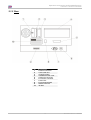
Spitfire 65/90 Extreme
English
Operation Instructions Spitfire 65/90 Extreme
English
This page is intentionally left blank
2
AP-77140 – Rev. 1.1 – 05/04/07
Operation Instructions Spitfire 65/90 Extreme
English
COPYRIGHT NOTICE
COPYRIGHT © 2007 Mutoh Europe N.V. All rights reserved.
This document may not be reproduced by any means, in whole or in part, without written permission of the
copyright owner.
This document is furnished to support the Mutoh Spitfire 65/90 Extreme Printer. In consideration of the
furnishing of the information contained in this document, the party to whom it is given, assumes its custody
and control and agrees to the following:
The information herein contained is given in confidence, and any part thereof shall not be copied or
reproduced without written consent of Mutoh Europe N.V.
This document or the contents herein under no circumstances shall be used in the manufacture or
reproduction of the article shown and the delivery of this document shall not constitute any right or license to
do so.
April 2007
Published: Mutoh Europe N.V., Archimedesstraat 13, B-8400 Oostende, BELGIUM
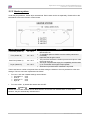
WEEE regulations
Environmental information
Disposal of your old product
Your product is designed and manufactured with high quality materials and components, which
can be recycled and reused.
When this crossed-out wheeled bin symbol is attached to a product it means the product is
covered by the European Directive 2002/96/EC
Please inform yourself about the local separate collection system for electrical and electronic
products.
Please act according to your local rules and do not dispose of your old products with your normal
household waste. The correct disposal of your old product will help prevent potential negative
consequences for the environment and human health.
3
AP-77140 – Rev. 1.1 – 05/04/07
Operation Instructions Spitfire 65/90 Extreme
English
This page is intentionally left blank
4
AP-77140 – Rev. 1.1 – 05/04/07
Operation Instructions Spitfire 65/90 Extreme
English
TABLE OF CONTENTS
1
Safety Instructions.................................................................................. 7
1.1
1.2
1.3
1.4
2
Product Overview ................................................................................. 13
2.1
2.2
2.3
3
Done by end user ............................................................................. 37
Done by authorised Mutoh technician .............................................. 47
Preparations before printing................................................................ 49
5.1
5.2
5.3
5.4
6
Switching the power ON/OFF ........................................................... 23
Loading media .................................................................................. 24
Replacing ink cassettes .................................................................... 27
Replacing the cutting blade .............................................................. 29
Replacing the waste bottle................................................................ 30
Working with Mutoh’s SmartChip management system. .................. 31
Transfer and transportation .............................................................. 35
LongStore ......................................................................................... 36
Periodical maintenance........................................................................ 37
4.1
4.2
5
Part names and functions ................................................................. 13
In-the-box contents ........................................................................... 18
Installation requirements................................................................... 22
Basics .................................................................................................... 23
3.1
3.2
3.3
3.4
3.5
3.6
3.7
3.8
4
Introduction ......................................................................................... 7
Warnings, Cautions and Notes ........................................................... 7
Important safety instructions............................................................... 7
Warning labels .................................................................................. 10
Using media...................................................................................... 49
Set the correct distance adjust (step) ............................................... 51
I² Technology .................................................................................... 56
Printing flow ...................................................................................... 58
Printer menu.......................................................................................... 59
6.1
6.2
6.3
6.4
6.5
How to work in the menu .................................................................. 59
Operation panel IN standby mode .................................................... 61
Operation panel during printing ........................................................ 64
Operation panel after printing ........................................................... 67
Menu overview (1/7 – 7/7) .............................................................. 69
5
AP-77140 – Rev. 1.1 – 05/04/07
Operation Instructions Spitfire 65/90 Extreme
English
This page is intentionally left blank
6
AP-77140 – Rev. 1.1 – 05/04/07
Operation Instructions Spitfire 65/90 Extreme
CHAPTER 1 : SAFETY INSTRUCTIONS
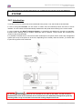
1 SAFETY INSTRUCTIONS
1.1 INTRODUCTION
This chapter explains the meaning of safety terms for personnel who operate this equipment, important
safety instructions, and the positions of the warning labels.
Important
Be sure to follow all instructions and warnings in this manual when using the equipment.
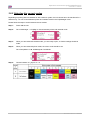
1.2 WARNINGS, CAUTIONS AND NOTES
Safety terms in this manual and the contents of warning labels attached to the printer are categorized into
the following three types depending on the degree of risk (or the scale of accident).
Read the following explanations carefully and follow the instructions in this manual.
Safety terms
Important
Caution
Notes
Details
Must be followed carefully to avoid death or serious bodily injury
Must be observed to avoid bodily injury (moderate or light) or damage to your equipment
Contains important information and useful tips on the operation of your printer
1.3 IMPORTANT SAFETY INSTRUCTIONS
General safety instructions that must be observed to use the equipment safely are explained below.
•
Do not place the printer in the following areas. Doing so may result in the printer tipping or falling over
and causing injury.
{ Unstable surfaces
{ Sloping floors
{ Areas subject to vibration by other equipment
•
Do not stand on or place heavy objects on your printer. Doing so may result in the printer tipping or
falling over and causing injury.
•
Do not cover the ventilation hole of your printer with cloth, such as a blanket or table cloth. Doing so
could obstruct ventilation and cause fire.
•
Do not place the printer in humid and dusty areas. Doing so may result in electrical shock or fire.
•
Do not use a damaged power cable. Doing so may result in electrical shock.
•
Do not attempt to plug in electrical plugs with wet hands. Doing so may result in electrical shock.
•
Do not connect earth cables in the following areas.
Gas pipes → Doing so may cause fire or an explosion.
{ Earth terminals for telephone line or lightening rod → Doing so may cause a large flow of voltage if
lightening occurs.
{ Water pipes or faucets → If there is a plastic part in the pipe, the earth will not work properly.
{
•
Do not insert or drop metal or inflammable objects into openings, such as ventilation outlets. Doing so
may result in electrical shock and fire.
7
AP-77140 – Rev. 1.1 – 05/04/07
Operation Instructions Spitfire 65/90 Extreme
CHAPTER 1 : SAFETY INSTRUCTIONS
•
Stop using your printer if a liquid has been spilled into it. This may cause electrical shock or fire. Power
OFF the printer as soon as possible, unplug the power cord and contact your local MUTOH dealer.
•
Be sure to use the attached cable. Otherwise, electrical shock or fire may occur.
•
Be sure to use the specified voltage (AC 100 V to 120V, or AC 220V to 240V). Otherwise, electrical
shock or fire may occur.
•
Use electricity directly from a power outlet (AC 100 V to 120V, or AC 220V to 240V). Do not put many
loads on one electrical output. Otherwise, heat may be generated and cause fire.
•
Be sure to use an outlet with an earth terminal and use the terminal correctly. Otherwise, electrical
shock or fire may occur.
•
Follow the instructions below when handling the power cable.
Do not modify the cable.
Do not put heavy objects on the cable.
Do not bend, twist or pull the cable.
Do not wire the cable near equipment that generates heat.
{
{
{
{
•
Follow the instructions below when handling the power plug. Otherwise, fire may occur.
Wipe away dust and any other residue before inserting the plug.
Ensure that the plug is firmly inserted as far as it can go.
{
{
•
When handling the foot switch, be aware of the following:
Do not place anything heavy on the foot switch.
Do not bend the cable of the foot switch with force and do not pull.
Do not place the foot switch near thermal devices.
{
{
{
•
When handling ink cassettes, be careful that ink does not get in your eyes or on your skin. However, if
this happens, flush immediately with water and wash skin with soap. Otherwise, your eyes may become
congested or inflamed slightly. If you feel discomfort, consult a doctor immediately.
•
Do not disassemble ink cassettes. Otherwise, ink may get in your eyes or on your skin.
•
Spitfire Mild Solvent Inks
{
General information:
Symptoms of poisoning may even occur after several hours; therefore medical observation for at
least 48 hours after the accident.
After inhalation:
Supply fresh air. If required, provide artificial respiration. Keep patient warm. Consult doctor if
symptoms persist.
In case of unconsciousness, place patient stably in side position for transportation.
After skin contact: the product does not irritate the skin.
After eye contact: Rinse opened eye for several minutes under running water.
After swallowing: medical advice or consult doctor.
•
Be careful not to pinch your fingers when opening and closing the cover of the ink compartment.
•
Be careful not to pinch your fingers when opening and closing the front cover.
•
Follow the instructions below when connecting the network interface cable. Otherwise, electrical shock
or fire may occur.
{ Do not touch the connector.
{ Do not connect the network cable connector which has not the same specifications as the interface
board.
•
When cutting the roll media, be careful of the following. Incorrect handling can result in injury to the
hands and fingers from the razor blade.
{ When holding the media, do not place fingers over the media cut groove.
{ Move the razor blade slowly along the media cutting groove.
8
AP-77140 – Rev. 1.1 – 05/04/07
Operation Instructions Spitfire 65/90 Extreme
CHAPTER 1 : SAFETY INSTRUCTIONS
•
Do not use thinner, benzene, alcohol or other active agents. Doing so may result in damage or paint
peeling from the casing.
•
Be careful not to spill water inside the printer. Doing so may result in a short circuit.
•
Be careful not to touch the heaters during or after operation. Doing so may result in burns.
•
Only use Spitfire Mild Solvent Ink and appropriate cleaning liquid.
•
Never open the covers fixed with screws, except the left cover. Doing so may result in electrical shock
or a malfunctioning of the printer.
•
Do not touch the cutter blade. Doing so may result in bodily injury.
•
Do not cut hard objects or drop the cutter. Doing so may damage or chip the cutter blade.
•
Do not bend or pull the waste fluid tube. Doing so may cause that the waste fluid will leak out and
malfunction of the product.
•
Do not touch the cleaning wiper or the head cap unit with bare hands. Use a dust free cloth and gloves
to clean.
•
Do not tilt the printer, stand it against a wall or turn it upside down. Doing so may cause ink to leak
inside the printer. Movement after transport is also not covered by the warranty.
•
When installing options, do not touch the elements on the circuit board. The elements on the boards can
be very hot and can cause burns.
•
Have four or more people unpack and assemble the printer.
•
When lifting the printer out of the packing box, be sure to remove the vinyl cover first, and then grab the
holding grips on the sides of the printer. Lifting the printer with the vinyl cover on may cause your hands
to slip and drop or damage the printer.
•
Have two or more people transport the printer.
•
Ensure that the plug has been disconnected from the power socket when it is not to be used for a long
time.
•
Earth wires must be connected to wires or terminals that fulfil the conditions below.
Earth terminals of power sockets
Earth wires with copper morsel that is at least 650 mm under the ground
{
{
•
Earth wires must be connected to wires or terminals that fulfil the conditions below.
•
Keep the printer horizontally during transportation.
•
Be sure to do the following before attaching options.
Power OFF the printer.
Unplug the power cord from the socket.
Unplug cables connected to the printer. Otherwise, damage to the printer or your computer may
occur.
{ Remove electrostatic charge from your clothes and body by touching the metal parts of the printer.
{ Electronic components such as the memory may malfunction if exposed to an electrostatic charge.
{
{
{
•
The equipment that you bought requires the extraction and use of natural resources for its production. It
may content hazardous substances for the health and the environment.
In order to avoid the dissemination of those substances in our environment and to diminish the pressure
on the natural resources, we encourage you to use the appropriate take-back system. Those systems
will re-use or recycle most of the materials of your end life equipment in a sound way.
If you need more information on the collection, re-use and recycling systems, please contact your local
or regional waste administration.
9
AP-77140 – Rev. 1.1 – 05/04/07
Operation Instructions Spitfire 65/90 Extreme
CHAPTER 1 : SAFETY INSTRUCTIONS
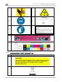
1.4 WARNING LABELS
The handling, attachment locations, and types of warning labels are explained below.
Warning labels are attached on areas which require attention. Read and understand the positions and
contents thoroughly before performing your work.
1.4.1 Handling the warning labels
Be sure to note the following when handling the labels.
•
•
•
Notes
Make sure that all labels can be recognized. If text or illustrations cannot be seen clearly, either clean
or replace the label.
When cleaning labels, use a cloth with water or neutral detergent. Do not use a solvent or gasoline.
If a warning label is damaged, lost or cannot be recognized, replace the label. When replacing warning
labels, contact your local MUTOH dealer.
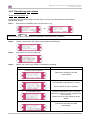
1.4.2 Locations and types of warning labels
The locations of warning labels are shown below.
1.4.2.1
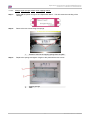
Location and types of warning labels on front part.
10
AP-77140 – Rev. 1.1 – 05/04/07
Operation Instructions Spitfire 65/90 Extreme
CHAPTER 1 : SAFETY INSTRUCTIONS
1
2
4-10
5
6-9
7
3
8
1.4.2.2
Location and types of warning labels on back part.
No.
Type
3
CAUTION
THIS UNIT HAS TWO POWER SUPPLY CORDS, WHEN WiNDING
UNIT IS PROVIDED. TO REDUCE THE RISK OF ELECTRICAL
SHOCK, DISCONNECT ALL POWER SUPPLY CORDS
BEFORE SERVICING.
4
11
AP-77140 – Rev. 1.1 – 05/04/07
Operation Instructions Spitfire 65/90 Extreme
CHAPTER 1 : SAFETY INSTRUCTIONS
12
AP-77140 – Rev. 1.1 – 05/04/07
Operation Instructions Spitfire 65/90 Extreme
CHAPTER 2 : PRODUCT OVERVIEW
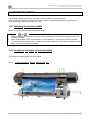
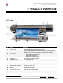
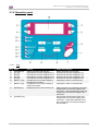
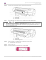
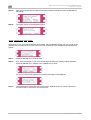
2 PRODUCT OVERVIEW
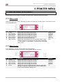
2.1 PART NAMES AND FUNCTIONS
Part names and functions are explained below.
2.1.1 Front
No
1
*
Name
Function
Heater plate
Supports and heats the media during printing.
2
Front cover
3
Carriage
Keeps the operator safe from the drive parts of the printer while it is
operating. Only open and/or close the cover to perform following
operations:
• Media setting and replacement
• Cutter blade replacement
• Cleaning the cleaning wiper
Drives and holds the print heads.
4
Operation panel
To control the printer.
5
Ink compartment cover
Covers the ink compartment.
6
Stand
Carries the main body.
7
Waste bottle assembly
Collects the waste fluid.
8
Winder*
Rolls up the roll media.
9
Front tension system
Keeps the media under tension.
10
Left maintenance covers
Covers the maintenance areas.
Only a 90” model comes standard with an Unwinder/Winder 100 system. For a 65” model, one has to choose between a Tensioning winder 30 or an Unwinder/Winder 100.
13
AP-77140 – Rev. 1.1 – 05/04/07
Operation Instructions Spitfire 65/90 Extreme
CHAPTER 2 : PRODUCT OVERVIEW
2.1.2 Rear
No
1
2
3
4
5
6
7
8
9
10
Connection
Ethernet connector
Card reader slot
SmartChip label
HardDisk bracket cover
Centronics connector
Foot switch connector
Power inlet
Environmental label
DB-25 connector
ID label
14
AP-77140 – Rev. 1.1 – 05/04/07
Operation Instructions Spitfire 65/90 Extreme
CHAPTER 2 : PRODUCT OVERVIEW
2.1.3 Heater system
Under the print platforms, heater strips are attached. Each heater can be set separately. Please refer to the
table below to know the function of each heater.
Heater element
Temperature
Pre-heater (Heater A)
20 – 50°C
Fixer (Heater B)
20 – 40°C
Post-Fixer (Heater C)
20 – 70°C
Dryer (Heater D)
20 – 50°C
•
•
•
•
•
•
Function
Open the pores to make the media more receptive for Spitfire
Mild Solvent Ink.
To establish optimum fixation onto the media (coated and
uncoated).
Optimizes the dot gain control.
The post-fixer finalizes the fixation process and helps to make
the prints touch-dry.
The dryer completes the drying for compatibility with the takeup in combination with higher output speeds.
Stickiness of printed banner materials is improved.
There have been a number of requests from the field, asking the heaters to be on by default for a few user
settings. This has now been implemented as follows:
•
For user 1 and user 8 default settings are as follows:
Pre heater A: 50°C
Fixer B:
40°C
Post Fixer C: 50°C
Dryer D:
50°C
{
{
{
{
•
For users 2 Î 7, by default the heaters are still OFF.
Notes
Please note some RIP software do not allow selection of the user from software side. In some cases,
however, they do automatically activate user 8.
15
AP-77140 – Rev. 1.1 – 05/04/07
Operation Instructions Spitfire 65/90 Extreme
CHAPTER 2 : PRODUCT OVERVIEW
2.1.4 Operation panel
2.1.4.1
Keys
No
1
2
3
4
5
6
Name
[POWER] key
[F1] key
[F2] key
[F3] key
[F4] key
[MENU ↑] key
7
[MENU ↓] key
8
[ENTER] key
Normal
Switch the printer ON and OFF
Executes the function assigned to F1.
Executes the function assigned to F2.
Executes the function assigned to F3.
Executes the function assigned to F4.
Changes the LCD monitor display to
the setup menu status.
Changes the LCD monitor display to
setup menu status.
Displays the print mode currently set.
9
[CANCEL] key
-
16
Setup menu display
Switch the printer ON and OFF
Executes the function assigned to F1.
Executes the function assigned to F2.
Executes the function assigned to F3.
Executes the function assigned to F4.
Changes the menu in reverse order.
Changes the menu in forward order.
Determines the new parameter value and
changes the LCD monitor display to the
next menu. Sets the parameter value and
changes the LCD monitor display to the
next menu.
Cancels the new parameter value and
changes the LCD monitor display to the
next menu. Clears the parameter value
and changes the LCD monitor display to
the next menu.
AP-77140 – Rev. 1.1 – 05/04/07
Operation Instructions Spitfire 65/90 Extreme
CHAPTER 2 : PRODUCT OVERVIEW
2.1.4.2
LCD and LED’s
No
10
Name
LCD monitor
Colour
-
Status
-
11
POWER lamp
Green
12
ERROR lamp
Red
ON
OFF
Flashing
13
DATA lamp
Orange
14
MEDIA SET lamp
Orange
OFF
ON
Flashing
OFF
ON
OFF
15
ROLL lamp
Orange
16
SHEET lamp
Orange
17
HEATER lamp
Orange
ON
OFF
ON
OFF
ON
Flashing
OFF
Function
The monitor displays the operation status and error
messages of the printer.
The printer is on.
The printer is off.
An error has occurred. The contents will be displayed on
the LCD monitor.
Either there is no error or the power is off.
The printer is receiving print data.
The printer is analyzing received data.
The printer is waiting to receive print data.
The pressure roller is in the release position.
Media has not been loaded.
The pressure roller is in the secured position.
The media has not been loaded.
The media type is set to roll media.
The media type is set to sheet media.
The media type is set to sheet media.
The media type is set to roll media.
The temperature of the heating elements is the requested
temperature.
The real temperature is the same as the requested
temperature.
The heating elements are warming up.
The real temperature is different as the requested
temperature.
The heating elements are powered OFF.
17
AP-77140 – Rev. 1.1 – 05/04/07
Operation Instructions Spitfire 65/90 Extreme
CHAPTER 2 : PRODUCT OVERVIEW
2.2 IN-THE-BOX CONTENTS
After unpacking the packaging box, inspect if the unit is not damaged and that all necessary parts are
present.
Notes
The contents of the packages may be different depending on the market where they are used. Contact
your local MUTOH dealer or distributor for details.
If any part is missing or broken, contact either of the following:
• The shop where you bought your MUTOH printer.
• Your local MUTOH distributor
2.2.1 Main unit packaging box
No
1
2
3
Description
Main unit
Waste bottle (not on image)
Accessory box (not on image)
Qty
1
1
1
2.2.2 Stand packaging box
No
1
2
Description
Stay
Foot
Qty
1
2
18
AP-77140 – Rev. 1.1 – 05/04/07
Operation Instructions Spitfire 65/90 Extreme
CHAPTER 2 : PRODUCT OVERVIEW
2.2.3 Accessories box
No
1
2
3
4
5
6
7
8
9
10
Description
Power cable
Plain washers M6
Spring washers M6
Foot switch
Hexagon socket head cap screw (M6 x 30)
Hexagon socket head cap screw (M6 x 16)
Assembly tool (hex. 5 mm)
Cable clamp
Screw driver
Media Retainer Set (2 pieces)
Qty
1
16
16
1
8
8
1
3
1
1
Notes
There are also two media sample rolls enclosed in the box of the printer, which can be used for the first
nozzle check and for the first prints.
19
AP-77140 – Rev. 1.1 – 05/04/07
Operation Instructions Spitfire 65/90 Extreme
CHAPTER 2 : PRODUCT OVERVIEW
2.2.4 Machine Starters Kit
1
2
5
3
6
7
9
12
8
10
13
No
1
2
3
4
5
6
7
8
9
10
11
12
13
14
15
4
11
14
Description
User’s Guide Spitfire Extreme
Quick installation Guide + CD
Instruction sheet machine starter kit
Getting Started with Mutoh’s 1-in-ALL
Spitfire Extreme logo
Keyboard label
Heater label
Harmful label
Maintenance label set (6 languages)
Power Cable
Mutoh knife
Spitfire Setup Cleaning
Spitfire Mild Solvent Cleaning
Ink Starter Set (1x6 or 2x4)
User maintenance kit 6 months
20
15
Qty
1
1
1
1
1
1
1
1
1
2
1
8
8
8
1
AP-77140 – Rev. 1.1 – 05/04/07
Operation Instructions Spitfire 65/90 Extreme
CHAPTER 2 : PRODUCT OVERVIEW
2.2.5 User Maintenance kit
Order number: KY-80229
Kit content:
No
1
2
3
4
5
6
Description
Sponge plate
Wipers
Spitting box sponge
Cleaning Liquid 250 ml
Instruction sheet
Good shape kit KY-80228*
Quantity
6
24
12
3
1
1
* Good shape kit order number: KY-80228
* Good shape kit content:
No
1
2
3
4
Description
Gloves
Pipette
Swabs
Polyknit wiper
Quantity
300
60
150
300
21
AP-77140 – Rev. 1.1 – 05/04/07
Operation Instructions Spitfire 65/90 Extreme
CHAPTER 2 : PRODUCT OVERVIEW
2.3 INSTALLATION REQUIREMENTS
An Authorized Mutoh technician will install your unit and will make the printer ready for its first job. A room
which meets the environmental and space conditions should be foreseen by the user.
Area
12.7m² (144ft²) or larger. Frontage of 4.7m (15.7ft) or greater.
Floor loading capability
2940 Pa (300kg/m²) or over
Electrical
AC 100-120V
AC 220-240V
60/50Hz±1Hz
AC100V-120V : 12A
AC220V-240V : 6A
Voltage
Frequency
Capacity
In order to protect the printer for over currents, short circuits and earth faults, the building
installation should be equipped with an automatic breaker double pole of 20 A and an earth leakage
switch of 300 mA.
Environmental
Recommended
working
environment
Operational
conditions
Rate of change
Storage
environment
Temperature: 23°C
Humidity: 55%, without condensation
Temperature: 18°C-28°C
Humidity: 40% to 80%, without condensation
Temperature: No more than 2°C per hour
Humidity: No more than 5% per hour
Temperature: 4°C to 50°C
Humidity: 40 to 80%, without condensation (When ink has been
discharged.)
Install the product on a flat surface that fulfils the following conditions.
a
b
c
d
e
1500 mm
1500 mm
2500 mm
600 mm
1250 mm
22
AP-77140 – Rev. 1.1 – 05/04/07
Operation Instructions Spitfire 65/90 Extreme
CHAPTER 3 : BASICS
3 BASICS
3.1 SWITCHING THE POWER ON/OFF
3.1.1 Turning the power ON
Turn the power of the unit ON according to following procedure.
Step 1 :
Press the [POWER] key of the operation panel, to turn the unit ON.
¾ The POWER lamp of the operation panel will light (green).
Step 2 :
The unit will start initial start-up operations.
Step 3 :
After finishing initial start-up operations, the unit will enter the normal
operating condition.
3.1.2 Turning the power OFF
Turn the power of the unit OFF according to the following procedure.
Step 1 :
Verify the following regarding the operational condition of the unit.
¾ There is no printing operation being performed.
¾ The operation panel is in a normal status.
Step 2 :
Press the [POWER] key of the operation panel to turn the unit OFF.
Step 3 :
Following message is displayed for 3 seconds on the operation panel.
Step 4 :
The product will perform the power OFF operation.
¾ Following message is displayed on the operation panel.
¾
¾
All lamps and the LCD of the operation panel will turn OFF.
The product will automatically turn the power OFF after performing a tubing flush.
23
AP-77140 – Rev. 1.1 – 05/04/07
Operation Instructions Spitfire 65/90 Extreme
CHAPTER 3 : BASICS
3.2 LOADING MEDIA
3.2.1 Loading roll media
Please refer to the User’s Guide of the Unwinder/Winder 100 or the T- winder to know how to load roll
media.
3.2.2 Loading sheet media
You can use the following sheet media with your printer.
Machine
Spitfire Extreme 65
Spitfire Extreme 90
Media Width
1653 mm
2280 mm
Printing Width
1643 mm
2250 mm
To load sheet media, follow the steps below.
Notes
If roll media is attached to the printer, wind the media up and then load the sheet media.
Step 1 :
Turn the printer on.
Step 2 :
The printer starts the initialize operation.
•
The following message is displayed on the operation panel.
Step 3 :
Verify if the sheet lamp on the operation panel is unlit.
Step 4 :
Press the [F4] key on the operation panel to lower the pressure rollers.
Step 5 :
•
The MEDIA SET lamp will light (orange).
•
The following message is displayed on the operation panel.
Open the front cover.
24
AP-77140 – Rev. 1.1 – 05/04/07
Operation Instructions Spitfire 65/90 Extreme
CHAPTER 3 : BASICS
Step 6 :
Load the sheet media into the insertion slot at the front of the printer.
1
2
Step 7 :
•
•
Sheet media
Insertion slot
Set the right edge of the media so that it is parallel with the media setting position.
Notes
The media set position is a guideline for setting up the media.
If the right edge of the sheet media is 5 mm or more from the media setting position, a media set error
may occur if the media is not detected. Make sure to set the right edge of the sheet media within 5
mm of the media setting position.
1
2
Sheet media
Media loading position
Step 8 :
Press the [F4] key on the operation panel to lower the pressure rollers.
• The MEDIA SET lamp will turn off.
Step 9 :
Close the front cover.
Step 10 : The media initial menu is displayed on the operation panel.
25
AP-77140 – Rev. 1.1 – 05/04/07
Operation Instructions Spitfire 65/90 Extreme
CHAPTER 3 : BASICS
3.2.3 Setting media type
The procedure for setting media type is explained below.
Step 1 :
Turn the printer on and load the media.
¾ Once the media has been set, the media initial menu will be displayed.
Step 2 :
Press one of the following keys on the operation panel, and select the current media type.
¾ When alternating roll/sheet media selection: [F2]
¾ When changing from media loading: [F3]
¾ When changing media type: [F4]
Setup items
Media type
Key
F2
Parameters
Roll media
Sheet media
Lever Down/Up
F3
Lever up
Lever down
Media Type
F4
User 1
User 2
User 3
User 4
User 5
User 6
User 7
User 8
Step 3 :
•
Description
Alternates the roll media type.
• Roll media: Set when loading roll media.
• Sheet media: Set when loading sheet media.
Switches between up and down motion of the pressurizing
lever.
Use this when starting over from the media setup.
Set media type for printing.
For setup values of printing operation, eight settings of "user 18" can be set.
Refer to ‘Menu Overview’
Press the [Enter] key on the operation panel.
¾ The media type has been set.
¾ "Media Initial" is displayed on the LCD, and the printer starts the media initial operation.
Notes
The printer starts the media initial operation if you :
o Press the [CANCEL] key on the operation panel
o Leave the printer for 10 seconds without doing anything
Step 4 :
When the media initial operation finishes, the printer moves to normal status.
¾ The setting media loading procedure has been completed.
26
AP-77140 – Rev. 1.1 – 05/04/07
Operation Instructions Spitfire 65/90 Extreme
CHAPTER 3 : BASICS
3.3 REPLACING INK CASSETTES
3.3.1 Replacement time
Replace ink cassettes in the following situations:
a. The ink cassette is almost empty:
o
The following message will be displayed:
o
Printing operation will continue.
o
Prepare new ink cassettes before they are totally empty.
b. The ink cassette is empty:
o
The following message is displayed on the operation panel.
o
Printing operation will stop.
o
Replace with a new ink cassette as soon as possible.
Notes
When the ink runs out or is low, the ink colour is indicated as follows:
• 1-8: The number of the ink cassette slot (Refer to ‘Installing ink cassettes’)
• All: All inks
3.3.2 Types
•
•
Notes
The printer is designed for use with Spitfire Mild Solvent Ink cassettes. If you do not genuine products,
printouts may become faint and the printer will not be able to detect the end of ink.
The warranty will not cover (repairs will require a fee) a breakdown.
Please refer to the pricing sheet for more info about the Spitfire Mild Solvent ink and cleaning.
27
AP-77140 – Rev. 1.1 – 05/04/07
Operation Instructions Spitfire 65/90 Extreme
CHAPTER 3 : BASICS
3.3.3 Replacement procedure
Follow the steps below to replace ink cassettes.
Step 1 :
If the printer is turned on, make sure of the following
• Printing or other operations are not performed.
• Make sure that the display on the operation panel shows the normal state.
• The MEDIA SET light on the operation panel goes off.
Step 2 :
Open the ink compartment cover.
1
Step 3 :
Ink Compartment
Remove the ink cassette from the ink cassette slot.
1
2
Ink cassette slot
Ink cassette
Step 4 :
Take the new ink cassette from its package.
Step 5 :
Install the ink cassette following the steps in "Installing ink cassettes".
Step 6 :
Close the cover of the ink compartment.
Step 7 :
Make sure that the display on the operation panel returns to normal status.
28
AP-77140 – Rev. 1.1 – 05/04/07
Operation Instructions Spitfire 65/90 Extreme
CHAPTER 3 : BASICS
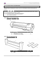
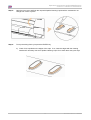
3.4 REPLACING THE CUTTING BLADE
3.4.1 Replacement time
Replace the cutting blade under the following conditions.
a. Media cannot be cut clearly
b. When the cut edge has scuffing
3.4.2 Replacement procedure
Follow the steps below to replace the cutting blade.
Step 1 :
If the printer is powered ON, make sure of the following:
¾ Printing or other operations are not performed.
¾ Make sure that the display on the operation panel shows the normal status.
¾ The MEDIA SET light on the operation panel goes off.
Step 2 :
Go to the H.Unlock menu (SetupMenu 5/7) and unlock the head.
Step 3 :
Open the front cover.
Step 4 :
While pressing the cutting blade holder tab, rotate the cutting blade holder lever in the direction
shown on the picture.
Step 5 :
Take out the cutting blade.
1
2
3
4
Cutting blade holder tab
Cutting blade holder lever
Pull down tab
Rotate lever as shown
Step 6 :
Insert the new cutter into the media cutting blade holder.
Step 7 :
While slightly pressing the cutting blade holder tab, return the cutting blade lever to its original
position.
Step 8 :
Close the front cover.
Step 9 :
Press the [ENTER] key on the operation panel.
¾ The carriage returns to its original position and returns to menu 6/7.
Step 10 : Cutting blade replacement has been finished.
29
AP-77140 – Rev. 1.1 – 05/04/07
Operation Instructions Spitfire 65/90 Extreme
CHAPTER 3 : BASICS
3.5 REPLACING THE WASTE BOTTLE
3.5.1 Replacement Time
Replace the waste liquid tank when following message is displayed.
3.5.2 Replacement Procedures
Follow the steps below to replace the waste liquid tank.
Step 1 :
Step 2 :
Check the following if the power of the printer is ON.
• Printer is not printing.
• Operation panel is in its main screen.
• Media setting light on the operation panel is off.
Follow "Menu setup on the operation panel" and display the tank replacement menu on the
operation panel.
Step 3 :
Open the cap of the waste liquid tank.
Step 4 :
Remove the waste liquid tank from the tank tray of the stand.
Notes
Put the used waste liquid tank in a plastic bag and follow the local regulations when disposing.
Step 5 :
Open the cap of a new waste liquid tank and put the tank to the printer.
Step 6 :
Press the [ENTER] key on the operation panel.
Step 7 :
The replacement of the waste liquid tank has been completed.
30
AP-77140 – Rev. 1.1 – 05/04/07
Operation Instructions Spitfire 65/90 Extreme
CHAPTER 3 : BASICS
3.6 WORKING WITH MUTOH’S SMARTCHIP MANAGEMENT
SYSTEM.
3.6.1 Introduction
To be able to print, ink volume has to be transferred to the printer. If not, the file will not be launched.
In case of using ink cassettes, the ink volume is written onto the smartchips which are stuck to the ink
cassette. The ink volume will be automatically transferred to the printer when working in the correct mode.
In case of working with Mutoh’s Bulk Ink System, no smartchips are attached to the bulk ink cartridges;
therefore when ordering bulk ink bottles, smartchips will be foreseen. These contain the necessary ink
volume for this particular bottle.
It is possible to transfer the ink volume from these smartchips to the printer via the smart chip management
system (slot on top of the printer or at the rear, depending on the model). After the transfer, you will be able
to print as long there is ink volume left.
Important
Do not pull any SmartChip cards from ink cassettes to use them in the reader. The ink volume on
the SmartChip cards of the cassettes can be transferred to the SmartChip management system by
scanning them one by one. Please find in the next coming chapters more info.
31
AP-77140 – Rev. 1.1 – 05/04/07
Operation Instructions Spitfire 65/90 Extreme
CHAPTER 3 : BASICS
3.6.2 Selecting the correct modes
Depending on printing with ink cassettes or with a bulk ink system, the ink volume has to be transferred in a
different way. You can choose between printer and cassette mode in the ChipManager menu:
Please follow the steps to switch between the two modes:
Step 1 :
Power ON the unit.
Step 2 :
Go to InkManager → ChipMgr to choose between printer and cassette mode
Step 3 :
When you have selected cassette mode, you are ready to print, no further settings should be
made.
Step 4 :
When you have selected printer mode, the colour mode should be set.
Go to SetupMenu 5/7 ► InkManager ► ColorMode
Step 5 :
Choose between 2*4_Symm or 1*6
32
AP-77140 – Rev. 1.1 – 05/04/07
Operation Instructions Spitfire 65/90 Extreme
CHAPTER 3 : BASICS
3.6.3 Transferring ink volume
Via the smart chip reader slot
Please follow the instructions below to transfer the ink volume on the SmartChips to the SmartChip
Management System.
Step 1 :
Browse to the ChipStatus menu and press the F1 key.
►
Notes
Be sure to be in printer mode, otherwise “ChipStatus” will be replaced by “InkStatus”.
Step 2 :
Insert the SmartChip in the reader slot and press the ENTER key.
Step 3 :
The system will scan the reader slot.
Step 4 :
Perform the correct action based on the displayed message.
IF…
THEN…
a cleaning card is detected
Remove the SmartChip card and
press ENTER
a valid card is found
Press ENTER to transfer the ink volume
Press CANCEL to quit the operation
no valid card is found
Remove the SmartChip card. You will be
asked if you want to scan the cartridge slots
for ink volume.
Please refer to the next chapter for all the
details.
the total printer chip value exceeds 40 000 ml
The transfer has been cancelled
automatically.
33
AP-77140 – Rev. 1.1 – 05/04/07
Operation Instructions Spitfire 65/90 Extreme
CHAPTER 3 : BASICS
Step 5 :
Remove the SmartChip card after the transfer has been finished and press the ENTER key
afterwards.
Step 6 :
The printer returns to the ChipStatus menu.
Via the Cassette slots of the printer.
When there is no or an invalid SmartChip card inserted, the management system will ask to scan all the
cassette slots and transfer the rest ink volume from the SmartChip on the cassette to the management
system.
Step 1 :
Press the ENTER key to scan all slots.
Step 2 :
If ink value is detected on one of the SmartChips, the following message will be displayed.
Press the ENTER key to transfer or the CANCEL key to abort.
If there is no ink volume detected, the following message will be displayed
Step 3 :
The management system will scan until it found a SmartChip with ink volume, repeat this
procedure until no ink volume is found anymore.
34
AP-77140 – Rev. 1.1 – 05/04/07
Operation Instructions Spitfire 65/90 Extreme
CHAPTER 3 : BASICS
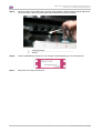
3.7 TRANSFER AND TRANSPORTATION
This section explains transferring and transporting the printer.
3.7.1 Transferring the printer
Following are instructions for transferring the printer.
(1) Before the transfer
If you are using the stand, follow the steps below to transfer the printer.
Step 1 :
Make sure the printer is turned off.
Step 2 :
Make sure the head is in the right edge position (capping position).
Step 3 :
Disconnect the power cable and all other cables.
Step 4 :
The four adjusters are turned in the direction shown on the diagram.
Step 5 :
Transfer the printer.
Notes
The caster attached to the stand has been designed for transferring the printer during short distances.
1
2
Adjuster
Caster
(2) After the transfer
Follow the steps below to prepare the printer to be used after the transfer.
Step 1 :
Make sure that you place the printer on an adequate place.
Step 2 :
Connect the power cable and other cables.
Step 3 :
Perform a nozzle check to check if the printer head has clogged.
Step 4 :
Perform a fine adjustment of image quality.
3.7.2 Transporting the printer
When you transport the printer, the printer should be repacked in the original box and packing materials, to
protect it from vibration or impact.
The printer should be in long store conditions.
35
AP-77140 – Rev. 1.1 – 05/04/07
Operation Instructions Spitfire 65/90 Extreme
CHAPTER 3 : BASICS
3.8 LONGSTORE
When transporting your printer or leaving your printer unattended for five days or more, it is highly
recommended to LongStore the printer in order not to damage the heads and/or complete ink system. This
means that the complete ink channel system will be filled with Spitfire Mild Solvent cleaning liquid.
3.8.1 Procedure to LongStore
Go to the LongStore menu (SetupMenu 5/7 ► InkManager 2/2 ► LongStore ► F2)
The process consists of several cleaning loadings, several air loadings and one ink loading. On the display
of the operation panel a time indication is mentioned on the fourth line.
Message
1. Please remove cart.
2. Ink Discharge
3. Please insert Cleaning cart.
4. During washing wait for a while
5. Ink not filled [ALL]
6. Power OFF
Time
29
Notes
When a cleaning cassettes is empty during LongStore procedure, remove the empty one and replace it by a
new one. Only the last cycle will be repeated. Although, the full time (29 minutes) is mentioned again on the
panel.
After powering OFF the machine, the tubings in the waste bottle should be mounted on the nipple plate at
the bottom of the machine. This to prevent air is coming in the ink system which will dry out the heads.
3.8.2 Starting up after a LongStore
Message
1. Power ON without Ink Cassettes installed.
2. Insert Cartridges
3. Auto InkFill
Time
9
Notes
When powering ON and the ink cassettes are already installed, the message “Not Original Ink” will be
displayed. Remove 1 and reinsert it to continue the procedure.
36
AP-77140 – Rev. 1.1 – 05/04/07
Operation Instructions Spitfire 65/90 Extreme
CHAPTER 4 : PERIODICAL MAINTENANCE
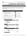
4 PERIODICAL MAINTENANCE
4.1 DONE BY END USER
This section describes the periodical services required for this machine. The periodical services ensure
stable printout quality of the machine. In the periodical services, some service parts may be checked,
cleaned, or replaced.
Perform periodical inspections according to the table below.
N
Action
Frequency
1
2
3
Clean wipers
Flush caps in maintenance station
Clean the edges of the caps in maintenance station
Daily maintenance
4
5
Clean the area around the caps
Clean around bottom of the heads
Weekly maintenance
6
7
Change the wipers
Change upper sponge at back of the capping station
Monthly maintenance
8
Replacing the sponge in the spitting box
2 weekly maintenance
Available kits for the end user and their order numbers
1. User and good shape kit for 6 months
No
1
2
3
4
5
6
KY-80229
Description
Quantity
Sponge plate
Wipers
Spitting box sponge
Cleaning Liquid 250 ml
Instruction sheet
Good shape kit
6
24
12
3
1
1
KY-80228
2. Good shape kit
No
Description
Quantity
1
2
3
4
Gloves
Pipette
Swabs
Polyknit wiper
300
60
150
300
3. Long store kit
KY-80230
No
Quantity
1
2
Description
Spitfire Mild Solvent Cleaning Liquid
Ink kit
Black
Cyan
Magenta
Yellow
8
2
2
2
2
T17S250CLN
4. Solvent cleaning in a bottle
37
AP-77140 – Rev. 1.1 – 05/04/07
Operation Instructions Spitfire 65/90 Extreme
CHAPTER 4 : PERIODICAL MAINTENANCE
4.1.1 Daily Maintenance
Before every print, perform a nozzle check. If some nozzles are missing or misfiring, perform cleaning cycles
until all nozzles are in good shape.
We advise to run a normal or a powerful cleaning cycle to recover the nozzles.
At the end of the day, when you will shut down the printer, the ink has to be removed from some parts, so it
cannot harden. Otherwise, some parts will break down or result in bad print quality.
Notes
In the box you will find a Good Shape Kit to perform the daily maintenance. Normally this is enough for 6
months. In case you’re out of stock, you can order a new kit at Mutoh Order Entry Department. The product
code of the good shape kit is KY-80228
Step 1 :
Power ON the printer and go to the “WiperClean-Menu”. This will cause the unlocking of the
carriage.
Step 2 :
Clean the wipers with a polyknit wiper. Use some Spitfire Cleaning Liquid to remove drops of ink.
Be sure to wear gloves.
Step 3 :
Perform a tubing flush (F4 in Menu 6/7)
38
AP-77140 – Rev. 1.1 – 05/04/07
Operation Instructions Spitfire 65/90 Extreme
CHAPTER 4 : PERIODICAL MAINTENANCE
Step 4 :
Open the front cover and flush the caps with Spitfire Cleaning Liquid until the mousses do not
change from colour anymore.
Step 5 :
To stop the tubing flush cycle press the ENTER key.
I)
Check if ink is spoiled on the edges of the caps. If so, clean the edges with the cleaning
swab and if necessary use some Spitfire Cleaning Liquid. If not clean them every two days.
39
AP-77140 – Rev. 1.1 – 05/04/07
Operation Instructions Spitfire 65/90 Extreme
CHAPTER 4 : PERIODICAL MAINTENANCE
4.1.2 Weekly Maintenance
At the end of the week, ink has to be removed from some parts, so it cannot harden. Otherwise, some parts
will break down or result in bad print quality. After performing a weekly maintenance, do not forget to perform
the daily maintenance afterwards.
Step 1 :
Power ON the printer and go to the “WiperClean-Menu”. This will cause the unlocking of the
carriage.
Step 2 :
Clean the area around the caps with a polyknit wiper. If you see ink, dust or some thing else,
clean it immediately so it can not influence the print quality.
Step 3 :
Open the left maintenance covers by loosening the four screws.
Step 4 :
Slide the carriage into the left maintenance area.
40
AP-77140 – Rev. 1.1 – 05/04/07
Operation Instructions Spitfire 65/90 Extreme
CHAPTER 4 : PERIODICAL MAINTENANCE
Step 5 :
Clean the edges of the heads with a cleaning swab wetted by Spitfire Cleaning Liquid. Make sure
you do not touch, clean the nozzle plate; this would lead to poorer print quality.
1
2
Cleaning Swabs
Gloves
Step 6 :
Press the ENTER key when done. The carriage will automatically go to its home position.
Step 7 :
Now perform the daily maintenance.
41
AP-77140 – Rev. 1.1 – 05/04/07
Operation Instructions Spitfire 65/90 Extreme
CHAPTER 4 : PERIODICAL MAINTENANCE
4.1.3 Monthly Maintenance
4.1.3.1
Replacing the wipers
Step 1 :
Power ON the printer and go to the “WiperClean-Menu”. This will cause the unlocking of the
carriage.
Step 2 :
Slide the carriage to the left side of the machine.
Step 3 :
Remove the old wipers with a pair of tweezers
Step 4 :
Before inserting a new wiper, moisten the wiper with Spitfire Cleaning Liquid.
Step 5 :
Insert the moistened wiper with a pair of tweezers.
Be sure to insert the wiper
correctly as shown below:
Be sure that the wiper clicks in the wiper
holder!
When standing in front of
the machine.
Step 6 :
•
•
Close the front cover and press the [ENTER] key. The head will cap in.
Notes
Be careful not to break the lips of the wiper arm while installing the wipers.
Do not touch the wipers with your bare hands to avoid fat or dirt get in contact with the wipers and
automatically the nozzle plate. Use a pair of tweezers to avoid this. Clean wipers with appropriate
cleaning liquid in case of dirt.
42
AP-77140 – Rev. 1.1 – 05/04/07
Operation Instructions Spitfire 65/90 Extreme
CHAPTER 4 : PERIODICAL MAINTENANCE
4.1.3.2
Change upper sponge at back of the capping station.
Step 1 :
Power ON the printer and go to the “WiperClean-Menu”. This will cause the unlocking of the
carriage.
Step 2 :
Remove the two screws fixing the sponge.
1
Step 3 :
Screws to remove the capping sponge from the plate
Replace the sponge and tighten it again to the plate with the two screws.
1
2
Capping sponge
Plate
43
AP-77140 – Rev. 1.1 – 05/04/07
Operation Instructions Spitfire 65/90 Extreme
CHAPTER 4 : PERIODICAL MAINTENANCE
4.1.3.3
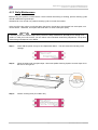
Replacing the sponge in the spitting box.
Notes
Use gloves and tweezers to change the absorbent in the flushing box.
Step 1 :
Unlock the head
Step 2 :
The carriage moves to the waiting position for replacing the flushing sponge.
Step 3 :
Remove the old absorbents with tweezers.
1
2
3
Step 4 :
Install the new absorbents in the flushing box. Make sure that the 2 holes are on the right side of
the flushing box and that the pins of the black box are in the holes of the absorbent.
1
2
Step 5 :
Sponge (KY-42889)
Tweezers
Gloves
Two holes
Pin of black box
Lock the head.
44
AP-77140 – Rev. 1.1 – 05/04/07
Operation Instructions Spitfire 65/90 Extreme
CHAPTER 4 : PERIODICAL MAINTENANCE
4.1.4 Cleaning
You need to clean the printer periodically to keep it in best working condition.
Following are instructions for cleaning the printer.
4.1.4.1
Cleaning the outer case
(1) Cleaning frequency
Clean once a month.
(2) Cleaning procedure
Remove dust or smudges on the outer case with a soft cloth.
4.1.4.2
Cleaning the inside of the printer
(1) Cleaning frequency
Clean once a month.
(2) Cleaning procedure
The following are instructions for cleaning the inside of the printer.
Follow the steps below.
Step 1 :
Open the front cover.
Step 2 :
Use a soft brush to carefully clean away any dust or dirt on the pressure rollers.
1
2
Pressure rollers
Platen
Notes
Do not blow off media dust inside the printer using an air dusting machine. Doing so may cause noise to
occur from inside the printer.
Step 3 :
Use a cloth soaked in cleaning liquid and squeezes it well, wipe off media dust and ink from the
platen.
45
AP-77140 – Rev. 1.1 – 05/04/07
Operation Instructions Spitfire 65/90 Extreme
CHAPTER 4 : PERIODICAL MAINTENANCE
4.1.4.3
Head cleaning
If printouts become faint or partially missed, perform head cleaning to clean the surface of the head and the
nozzles.
Follow the steps below to perform head cleaning.
Step 1 :
Make sure that the state of the product is normal.
Step 2 :
Refer to "TestPrinting" to perform nozzle check printing.
Step 3 :
Check if the print head, referring to the diagram below.
Step 4 :
Check the printer is in the main screen.
Step 5 :
Press the [F2] key on the operation panel.
I)
The printer enters the cleaning menu.
Step 6 :
Press the [F2] key on the operation panel to change the parameters.
Key
F2
Parameter
Small
Normal
Strong
Step 7 :
Press the [ENTER] key on the operation panel to start the head cleaning.
Step 8 :
When the head cleaning has been completed, the printer returns to the main screen.
Step 9 :
Perform a nozzle check again and check the print head.
Description
Small cleaning is performed.
Normal cleaning is performed.
Strong cleaning is performed.
46
AP-77140 – Rev. 1.1 – 05/04/07
Operation Instructions Spitfire 65/90 Extreme
CHAPTER 4 : PERIODICAL MAINTENANCE
4.2 DONE BY AUTHORISED MUTOH TECHNICIAN
An Authorized Mutoh technician should check and replace some components of your printer on frequent
base (every 6 and 12 months).
Be sure to remind your distributor when the replacements should be done.
It is very important not to skip a maintenance intervention in order to maintain constant print quality and to
keep your warranty.
Please refer to the table below to know what the Authorized Mutoh technician should do.
N°
Action
10
11
12
13
14
15
16
17
18
19
20
Change dampers
Change pumps (*)
Change tubes from pumps -> Waste bottle
Change spitting box + tube + L connection
Change capping station
Change cap assembly maintenance station
Apply grease on head up-down cams when needed
Apply grease on Y-motor belt when needed
Apply grease on roller path – carriage when needed (**)
Apply grease on capping station camm + gears when needed
Dust removal in fan area underneath print platform
Maintenance
Cycle
10
11
12
13
14
15
16
17
18
19
20
•
•
1
2
3
4
Month
6
7
x
x
x
x
5
8
x
x
x
x
x
x
9
10
11
12
x
x
x
x
x
x
x
x
x
x
Notes
All cleaning in “Ink areas” must be done with Spitfire Mild Solvent cleaning.
Above maintenance cycle is based on use:
8 hours / day, 5 days / week and 44 weeks / year.
If machine is used more, maintenance periods will come earlier.
Available kits for Authorized Mutoh Technicians only and their part numbers:
maintenance cycle Kit 6 months
KY-80226
maintenance cycle kit 12 months
KY-80227
47
AP-77140 – Rev. 1.1 – 05/04/07
Operation Instructions Spitfire 65/90 Extreme
CHAPTER 4 : PERIODICAL MAINTENANCE
48
AP-77140 – Rev. 1.1 – 05/04/07
Operation Instructions Spitfire 65/90 Extreme
CHAPTER 5 : PREPARATIONS BEFORE PRINTING
5 PREPARATIONS BEFORE PRINTING
5.1 USING MEDIA
This section describes details on available media for the printer.
5.1.1 Media range
Please refer to Mutoh’s website (www.mutoh.be) for the media compatibility lists and much more information
on using, handling media.
Media Range
As one of the world's largest manufacturers of wide-format piezo inkjet printers, Mutoh Europe is
committed to deliver total solutions : machine, RIP software, inks and media with matching profiles,
i.e. anything you need to start production of top quality outputs in no time.
5.1.2 Cautions on handling media
When you handle media, please pay attention to the following.
•
Use recommended media in an appropriate environment. Following are the appropriate temperature
and humidity ranges for printing.
Recommended working environment
Rate of change
Temperature
23°C
Within 2°C per hour
Humidity
40% to 70%
Within 5% per hour
•
Do not use creased, damaged, torn, curled, or wrapped media.
•
The size of the recommended sheets can change at a fixed ratio according to the temperature changes
of the working environment. Before using sheet media, place the sheet in the working environment for at
least 30 minutes, to have it match to the temperature of the working area.
•
Printing before the media could accommodate to the printing environment may cause media jams due to
slippage or creases. This also adversely affects the quality of printing.
•
Media has a printable side and a non-printable side. If you print on a not printable side, blurring or slight
touching may occur.
•
Do not touch the printable side of media. Moisture or oil from hands affects the printing quality.
•
Do not leave the printer for a long time with media loaded. The media may curl resulting in misalignment,
media jams, or decreased printing quality. In particular, avoid this in winter, dry seasons, or during final
printing.
•
Do not lose the box or wrapping bag for storing media.
49
AP-77140 – Rev. 1.1 – 05/04/07
Operation Instructions Spitfire 65/90 Extreme
CHAPTER 5 : PREPARATIONS BEFORE PRINTING
5.1.3 Precaution on storing media
When storing media, pay attention to the following.
•
Do not store media in high temperature, high humidity, or direct sunlight.
•
Store sheet media in the original bag after unpacking.
•
Unused roll media must be removed from the scroller, rewound tightly, and stored in the original
wrapping bag and the box.
•
Do not wet media.
5.1.4 The printing area
The printing area is shown below.
(1) Roll media
(2) Sheet media
50
AP-77140 – Rev. 1.1 – 05/04/07
Operation Instructions Spitfire 65/90 Extreme
CHAPTER 5 : PREPARATIONS BEFORE PRINTING
5.2 SET THE CORRECT DISTANCE ADJUST (STEP)
Obtaining constant printing quality on a wide-format Piezo inkjet printer is not only determined by the working
environment, the RIP, the profiles, the inks and the media which are used. One of the key factors for
obtaining constant output quality is the correct distance adjustment, also called “step”, on your Mutoh inkjet
printer.
5.2.1 Basics about the step
Every image is printed in several print passes. After every pass, the media is fed an amount of millimetres.
When the step is not set correctly, the passes will overlap each other or will not be printed precisely next to
each other which results in white bands between two print passes.
Therefore a function, distance adjust (or step), is added to the menu to control this feed operation.
Refer to the table below for visual support
The passes overlap each other
► step between the print passes is too small
The passes are printed too far from each other
► step between the print passes is too large
Notes
It is recommended to start printing with a step of 100.00% and to adjust it afterwards. Once a step is set for
a particular media it will not change on following conditions:
• The step is only applicable on the printer in question and not interchangeable.
• The media manufacturer does not change any specifications (especially backing) of the media.
• The standard take-up system is used in combination with the I² technology.
• The optional unwinder/winder 100 is used.
Please refer to the next chapter to know where and how to change the step.
51
AP-77140 – Rev. 1.1 – 05/04/07
Operation Instructions Spitfire 65/90 Extreme
CHAPTER 5 : PREPARATIONS BEFORE PRINTING
5.2.2 How to change the step
1) Via the status screen
Step 1 :
Press
Step 2 :
Press
Step 3 :
Press
in the Ready to print screen
or
to change the step
2) While printing
Step 1 :
Press
while printing.
Step 2 :
Press
or
to change the step
52
AP-77140 – Rev. 1.1 – 05/04/07
Operation Instructions Spitfire 65/90 Extreme
CHAPTER 5 : PREPARATIONS BEFORE PRINTING
3) Via the printer interface
It is also possible to print a pattern via the firmware. But this is not that precisely as with the DVD.
Please follow the steps below:
Step 1 :
Go to the Dist. Adj. menu as follows.
▼
▼
▼
▼
▼
▼
▼
▼
Setup items
Dist.Adj.
Step 2 :
Parameters
Print 1
Change
Print 2
-
Description
Print the test file with intervals of ± 0.10%
Change the step (90.00 % - 110.00 %)
Print the test file with intervals of ± 0.20%
[CANCEL] key: to shift to the previous hierarchy menu.
Set the step to 100.00%.
53
AP-77140 – Rev. 1.1 – 05/04/07
Operation Instructions Spitfire 65/90 Extreme
CHAPTER 5 : PREPARATIONS BEFORE PRINTING
Step 3 :
Print pattern 1 or 2.
Step 4 :
Adjust the step with the
Step 5 :
Reprint the patterns until step is set correctly.
or
key
54
AP-77140 – Rev. 1.1 – 05/04/07
Operation Instructions Spitfire 65/90 Extreme
CHAPTER 5 : PREPARATIONS BEFORE PRINTING
5.2.3 Helpful tools for setting the step
The step can be set / changed in two different ways:
•
•
Using the enclosed DVD
Via the printer interface
Notice that your step will be set more precisely when using the files on the DVD instead of the ones
embedded in the firmware.
5.2.3.1
Using the DVD
Step 1 :
Insert the “GET STARTED WITH…” DVD (auto start-up)
Step 2 :
Follow the complete procedure described on the DVD until no overlap or gaps are visible in the
pattern.
Step 3 :
Afterwards print the pre-ripped print file on Mutoh’s One-in-ALL vinyl for verification
55
AP-77140 – Rev. 1.1 – 05/04/07
Operation Instructions Spitfire 65/90 Extreme
CHAPTER 5 : PREPARATIONS BEFORE PRINTING
5.3 I² TECHNOLOGY
Without weaving ON, an image is completed (formed) by printing a series of
complementary rectangular shaped stripes (bands, swaths, passes). Inherent to
classic inkjet printing is that ink drying effects, stepping mismatch, miss firing nozzles
show up in the printed image via ink bleeding and various types of banding. By
switching ON one of the weave patterns you will give the traditional rectangular print
swaths a wave-shaped look that will save you time and boost your output quality.
Difficult images will print smoother, banding will be suppressed (neutralized) and you
will have to spend less time fine-tuning your printer to create great looking output.
Moreover, when using wave-tuned profiles, you will be able to boost your printer’s colour gamut as the i²
(intelligent interweaving) technology allows depositing more ink, helping you to achieve higher colour
densities.
Setup items
Weaving (1/2)
Weaving (2/2)
Weaving (1/2 – 2/2)
Parameters
Sign / Quality
Picture / Speed
Stitch
Classic
Off
-
Description
Please refer to the table below to know what the different weaving
forms are and which one to use.
[CANCEL] key: To shift to the previous hierarchy menu.
56
AP-77140 – Rev. 1.1 – 05/04/07
Operation Instructions Spitfire 65/90 Extreme
CHAPTER 5 : PREPARATIONS BEFORE PRINTING
Weaving
method
Sign / Quality
User Tip
Preferred setting
for signage/poster
applications
containing big
areas with solid
colours or critical
gradients and for
photo quality
output on coated
media.
(small loss of
speed in 2 pass
modes)
Print Modes
Supported
720x720
540x720
Picture / Speed
Stitch
Creates a fine print
swath overlap.
Mildly improves
print quality versus
“Off” setting.
(lowest level of
interweaving)
4 pass
2 pass
4 pass
2 pass
4 pass
Default selection after
firmware installation
720x720
Preferred setting
for non-sign
images, pictures,
continuous tone
data.
(no speed loss)
2 pass
540x720
2 pass
4 pass
2 pass
4 pass
(*) 4-pass is a quality
mode and will always
use a tuned sign weave
pattern, even if picture is
selected from the panel /
RIP.
720x720
540x720
2 pass
4 pass
2 pass
4 pass
(*) 4 pass data will be
printed as classic
Classic
Use classic to
maintain classic
printer behaviour in
all print modes.
(prior to firmware
version 3.01)
All print modes
Off
Switches off any
kind of
overlap/weaving.
Useful when trying
to inspect
individual nozzle
behaviour or
checking the stepadjust.
All print modes
57
AP-77140 – Rev. 1.1 – 05/04/07
Operation Instructions Spitfire 65/90 Extreme
CHAPTER 5 : PREPARATIONS BEFORE PRINTING
5.4 PRINTING FLOW
The following flowchart gives you a view on which steps should be taken to make a print. This is a very short
summary of what should be done.
SELECT MEDIA
(Refer to the media compatibility lists on www.mutoh.be)
▼
LOAD MEDIA
(Refer to the chapter “Loading Media”)
▼
PERFORM NOZZLECHECK AND CLEANINGS IF NECESSARY
(Refer to the chapter “TestPrinting”)
▼
SELECT IMAGE
▼
LOAD DEDICATED PROFILE (∗) AND RIP IMAGE
(Refer to profiles section on www.mutoh.be)
▼
SET STEP
(Refer to chapter “Set the correct distance adjust”)
▼
DECIDE WHICH WEAVING PATTERN SHOULD BE USED (SIGN/PICTURE)
(Refer to chapter “I² technology”)
▼
PRINT IMAGE
∗
It is highly recommended to use one of the profiles Mutoh is making available on the website. A lot of parameters are included.
The most important ones are:
Ink an colour management related
•
Ink Restrictions
•
Linearization
•
Ink limits
•
ICC Profile
PrintMode related
•
Resolution
•
Amount of passes
•
Unidirectional – Bi Directional
•
Weaving ON – OFF
Media related
•
Heater settings
•
Media thickness
•
HeadHeight
The file name of each profile is build up in the same way
For example
58
AP-77140 – Rev. 1.1 – 05/04/07
Operation Instructions Spitfire 65/90 Extreme
CHAPTER 6 : PRINTER MENU
6 PRINTER MENU
6.1 HOW TO WORK IN THE MENU
Please find below all necessary information on how to switch, select and cancel menu items.
6.1.1 Main screen
When powering ON the printer, it will (when no errors occur) start up in its main screen. The function of each
key is explained below
1→
2→
4→
6→
No
1
2
3
4
5
6
7
Position
1st line
Left of 2nd line
Right of 2nd line
Left of 3rd line
Right of 3rd line
Left of 4th line
Right of 4th line
←3
←5
←7
Description
Displays the current status of the printer.
Displays the function assigned to [F1] key
Displays the function assigned to [F2] key
Displays the function assigned to [F3] key
Displays the function assigned to [F4] key
Displays the currently set media type
Displays the approximate amount of remaining media in meter.
However, the amount is displayed only when either "Roll media
1", "Roll media 2", or "Roll media 3" is selected in the Roll media
setting menu.
Example
Ready to print
Cut&Feed
Cleaning
Heaters
Lever Up
User 1 – 8
30 m
6.1.2 Menu screen
In the SetupMenu, changes can be made to the printer settings.
The content displayed on the LCD monitor of the operation panel is as follows:
1→
2→
4→
No
1
2
3
4
5
6
Position
1st line
Left of 2nd line
Right of 2nd line
Left of 3rd line
Right of 3rd line
4th line
←3
←5
←6
Description
Displays the setting menu name currently set.
Displays the function assigned to [F1] key.
Displays the function assigned to [F2] key.
Displays the function assigned to [F3] key.
Displays the function assigned to [F4] key.
Displays the currently available functions of the [F1] key to the
[F4] key or displays the page status if there are multiple pages
for the currently displayed setting menu.
59
Example
SetupMenu
InkStatus
OriginSet
TestPrint
MediaSet
1/7
AP-77140 – Rev. 1.1 – 05/04/07
Operation Instructions Spitfire 65/90 Extreme
CHAPTER 6 : PRINTER MENU
6.1.3 Changing between the screens
To change the printer status, follow the steps below.
6.1.3.1
From main screen to menu screen
Press either
screen 1/7 – 7/7
6.1.3.2
or
on the operation panel when the printer is in the main screen to go to menu
From menu screen to main screen
To switch from a menu screen to the main screen, following actions can be taken:
•
•
Press the [CANCEL] key on the operation panel.
Leave the printer for 3 minutes when the status is in the setting menu display.
or
▼
▼
▲
▲
60
or leave the printer idle for 3 minutes
AP-77140 – Rev. 1.1 – 05/04/07
Operation Instructions Spitfire 65/90 Extreme
CHAPTER 6 : PRINTER MENU
6.2 OPERATION PANEL IN STANDBY MODE
This section describes functions operated on the operational panel when the printer is in the normal status.
6.2.1 [F1] – Feeding, Cutting media and Step Adjust
When you want to feed media forward or backward, follow the steps below:
Step 1 :
Verify the following regarding the condition of the printer.
I) It is not currently printing
Step 2 :
Press the [F1] key of the operation panel.
I) To shift to the Cut&Feed menu.
Step 3 :
Press the [F3] key or the [F4] key on the operation panel.
I) The product will perform following operations:
Setup items
Cut & Feed
Key name
F1
F2
F3
F4
Parameters
Cut
Dist.Adj.
Forward
Backward
Description
Cut media
Set step
Feeds media forward.
Feeds media backward.
Notes
If "Take-Up Roll" is set in the media detection setup menu, the product will not operate even if the [F4] key
has been pressed.
6.2.2 [F2] - Cleaning the heads
When there are some missing nozzles, a cleaning should be done. Depending on the quantity of missing
nozzles and which head, a little, normal or powerful cleaning on head 1-2, head 3-4 or ALL could be done.
Step 1 :
Verify the following regarding the condition of the printer.
I) It is not currently printing
61
AP-77140 – Rev. 1.1 – 05/04/07
Operation Instructions Spitfire 65/90 Extreme
CHAPTER 6 : PRINTER MENU
Step 2 :
Press the [F2] key of the operation panel.
I) To shift to the cleaning menu.
Step 3 :
Press the [F1] key or the [F2] key on the operation panel.
I) The product will perform following operations:
Setup items
Cut & Feed
Step 4 :
Key name
F1
F2
Parameters
ALL, Head 1 – Head 2
Little, normal, powerful
Description
Clean ALL heads or head couple one or two
Set the intensity of a cleaning
Press the [ENTER] key to start the requested cleaning.
6.2.3 [F3] - Controlling the heater elements
If you want to change or check the heater elements, follow the steps below.
Step 1 :
Verify the following regarding the condition of the printer.
I) It is not currently printing
Step 2 :
Press the [F3] key of the operation panel.
I) To shift to the heater menu.
The ‘heater message’ can be one of the following:
o Heater standby
o Heater warming up
o Heater ready
‘A’ stands for the heater.
‘B’ stands for the fixer.
‘C’ stands for the post fixer.
‘D’ stands for the dryer.
‘S’ stands for the Set-temperature (requested temperature).
‘R’ stands for the Real-temperature (actual temperature).
6.2.3.1
Change the heater temperature
To change the temperature of one of the heaters, press the [F1-F4] key on the operation panel. The display
will mention the following:
Press the [F2] key to decrease the temperature.
Press the [F4] key to increase the temperature.
Press the [ENTER] key to confirm the requested temperature change.
Press the [CANCEL] key to leave the menu without changing the heater settings.
62
AP-77140 – Rev. 1.1 – 05/04/07
Operation Instructions Spitfire 65/90 Extreme
CHAPTER 6 : PRINTER MENU
6.2.3.2
Activate/ deactivate heaters.
In the second menu, press the [F1] key to activate or deactivate all heating elements.
In case the heating elements are activated, the display will mention “SET OFF”. By pressing the [F4] key
you can deactivate the heating elements. The display will mention “SET ON”.
In case the heating elements are deactivated, the display will mention “SET ON”. By pressing the [F4] key
you can activate the heating elements. The display will mention “SET OFF”.
Please note that after finishing a printing job (and no other print job is sent to the printer the heating elements
will keep their temperature for approximately 6 minutes. After 6 minutes the heating elements are powered
OFF.
6.2.4 [F4] - Operating the pressure rollers
When you want to switch the up and down movement of the pressure rollers follow the steps below.
Step 1 :
Press the [F4] key on the operation panel.
I)
The printer works as follows.
Status of the printer
The pressure rollers have been lowered
The MEDIA SET lamp switches OFF.
The pressure rollers have been raised.
The MEDIA SET lamp switches ON (orange).
Operation after the [F4] key has been pressed
The pressure rollers are lifted
The MEDIA SET lamp will turn on (orange).
The pressure rollers are lowered.
The MEDIA SET lamp will turn off.
Notes
You can also switch the up and down movement of the pressure rollers using the foot switch instead of the
operation panel.
6.2.5 [ENTER] - Print mode check
Use the following procedure to check the print mode currently set.
Step 1 :
Press the [ENTER] key on the operation panel.
I) The following information is displayed on the operation panel for three seconds.
Line 2
Line 3
Line 4
No.
1
2
3
Position
Line 2
Line 3
Line 4
Step 2 :
Description
The printing quality is displayed.
The interlace method is displayed.
The printing direction is displayed.
Reference
Refer to ‘Printing quality menu’
Refer to ‘InterLace Setup menu’
Refer to ‘Printing direction menu’
When the printing mode display closes, the product changes to its main screen.
63
AP-77140 – Rev. 1.1 – 05/04/07
Operation Instructions Spitfire 65/90 Extreme
CHAPTER 6 : PRINTER MENU
6.3 OPERATION PANEL DURING PRINTING
When sending a file to your printer, following messages can be displayed.
6.3.1 When heaters are not ready
When the heaters are not reached their target temperature, the following screen will be displayed.
Still, it is possible to start the print. However, the heater will continue to warm up in order to reach the
requested temperature.
Step 1 :
Press the F3 key to ENTER the HeaterStatus menu.
Step 2 :
Go to submenu 2/2 and press the F2 key to start the print.
6.3.2 When heaters are ready
When heaters are ready, the printer will start printing.
While printing, some actions can be taken.
6.3.2.1
[F1] - On the fly step adjustments.
In case of overlapped printing images or white lines on printing image, the step should be adjusted.
(+) Increase in case of overlap
(-)
Decrease in case of white lines between swats
Notes
For more details about step adjustment, please refer to “Media Feed Compensation”
64
AP-77140 – Rev. 1.1 – 05/04/07
Operation Instructions Spitfire 65/90 Extreme
CHAPTER 6 : PRINTER MENU
6.3.2.2
[F2] - Cleaning
While printing, it could be possible that some nozzles drop out, in that case, perform a little, normal or
powerful cleaning.
Please follow the steps below to perform a cleaning.
When there are some missing nozzles, a cleaning should be done. Depending on the quantity of missing
nozzles and which head, a little, normal or powerful cleaning on head 1-2, head 3-4 or ALL could be done.
Step 1 :
Press the [F2] key of the operation panel.
I) To shift to the cleaning menu.
Step 2 :
Press the [F1] key or the [F2] key on the operation panel.
I) The product will perform following operations:
Setup items
Cut & Feed
Step 3 :
6.3.2.3
Key name
F1
F2
Parameters
ALL, Head 1 – Head 2
Little, normal, powerful
Description
Clean ALL heads or head couple one or two
Set the intensity of a cleaning
Press the [ENTER] key to start the requested cleaning.
[F3] - Adjust heaters
While printing, the heater values can be changed. For example: when noticing cockling.
Please follow the steps below to adjust the heater temperatures.
Step 1 :
Press the [F3] key
Step 2 :
Following screen will be displayed
Step 3 :
Change the value of one or more heaters or switch them all off.
Notes
For more details about heater adjustment, please refer to “Controlling the heater elements on the Spitfire
Extreme printer”
65
AP-77140 – Rev. 1.1 – 05/04/07
Operation Instructions Spitfire 65/90 Extreme
CHAPTER 6 : PRINTER MENU
[F4] - Loading ink volume during printing
It is possible to load ink volume to the printer during printing.
There are two possible scenarios:
•
SmartChip management system is not empty yet and the printer keeps printing.
Press the F4 key to load ink volume.
•
SmartChip management system is empty and the printer stops printing but does NOT cancel the
print.
The following message will appear
Press the F4 key to load ink volume.
•
•
Notes
Please refer to chapter 4.10 to load ink volume properly.
Please note that the heaters will switch off after 15 minutes. After that point you will have to
reconfigure the heaters manually before resuming the print job. This is the same behaviour as
when a cassette gets empty.
66
AP-77140 – Rev. 1.1 – 05/04/07
Operation Instructions Spitfire 65/90 Extreme
CHAPTER 6 : PRINTER MENU
6.4 OPERATION PANEL AFTER PRINTING
The operations performed after printing, are described here.
6.4.1 Cut off media with the printer knife
The media cutting procedure is described below.
Roll media is automatically cut after printing when "Auto" is set on the cut media menu and roll media has
been set.
When the operation panel is in the main screen, and the product is in the following conditions, the media can
be cut on the desired position:
•
•
•
•
When roll media has been set:
If "OFF" is set on the cut media menu
If "Take Up Roll" has been set in the media detection setup menu
When sheet media has been set
Follow the steps below to cut the media.
Follow the steps below to cut the media.
Step 1 :
Make sure that the MEDIA SET lamp on the operation panel is off.
Step 2 :
Press the [F1] key on the operation panel to shift to the cut and feed menu.
Step 3 :
Feed media to the desired position using the [F3] and [F4] key.
Step 4 :
Press the [F1] key to cut the media.
I)
Press the [ENTER]-key to cut the media or the [CANCEL]-key to abort this operation.
Notes
If the front edge of the roll media is not straight when you load new roll media, you should cut its edge.
Cutting blades are consumable. Replace them at regular intervals following "Replacing the cutting blade".
67
AP-77140 – Rev. 1.1 – 05/04/07
Operation Instructions Spitfire 65/90 Extreme
CHAPTER 6 : PRINTER MENU
6.4.2 Manually cut off media
This section explains how to cut the media manually.
When "Manual" is set in the media cut menu, the media can be cut manually.
Cut the media according to the following procedure.
Step 1 :
Make sure that the MEDIA SET lamp on the operation panel is off.
Notes
After printing, the media is automatically transferred to the media cutting position.
Step 2 :
Press the [F1] key on the operation panel to shift to the cut and feed menu.
Step 5 :
Feed media to the desired position using the [F3] and [F4] key.
Step 3 :
Cut the roll media following the cutting groove.
68
AP-77140 – Rev. 1.1 – 05/04/07
Operation Instructions Spitfire 65/90 Extreme
CHAPTER 6 : PRINTER MENU
6.5 MENU OVERVIEW (1/7 – 7/7)
SetupMenu 1/7
Ink Status
Origin Set
(1/1)
Top
Bottom
Left
Right
Test Print
(1/2)
Setup
Adj. Uni-D
Nozzle Check
Adj. Bi-D
Palette
Maintenance
(2/2)
Media Set
(1/1)
Media
(1/2)
(2/2)
User 1
User 2
User 3
User 4
(1/3)
User 5
User 6
User 7
User 8
(2/3)
(3/3)
Cut Size
(1/1)
Auto
Length
Width
Top Feed
Media Cut
(1/1)
Off
Auto
Manual
Ink Dry Time
Head Height
(1/1)
Stiffness
(1/1)
Thickness
Heater
Drier
Fixer
PostFixer
Hstatus
Dist.Adj
(1/1)
Low
Middle
High
Soft
Normal
Print 1
Print 2
Change
SetupMenu 2/7
Print Mode
(1/1)
Prn Mode 1
Prn Mode 2
Prn Mode 3
Prn Mode 4
(1/2)
Condition
(1/5)
360 x 360
720 x 360
360 x 720
Diag 720
(2/5)
(3/5)
69
720 x 720
1080 x 1080
1440 x 720
720 x 1440
Diag 1440
1440 x 1440
2160 x 1080
1080 x 2160
Diag 2160
1pass
2pass
2 pass
1pass
2pass
1pass
2pass
2 pass
4 pass
4 pass
2 pass
2 pass
4 pass
4 pass
4 pass
4 pass
1pass few
4pass
4 pass
1pass few
4pass
1pass few
4pass
4 pass
4 pass
4 pass
AP-77140 – Rev. 1.1 – 05/04/07
Operation Instructions Spitfire 65/90 Extreme
CHAPTER 6 : PRINTER MENU
(4/5)
(2/2)
Direction
(5/5)
(1/1)
Repeat Prn
(1/1)
HeadSpeed
(1/1)
Weaving
(1/2)
(2/2)
ScanWidth
Command
(1/1)
Step
(1/1)
Resolution
(1/2)
(2/2)
Layout
Function
(1/1)
(1/1)
(1/1)
2880 x 1440
1440 x 2880
Diag 2880
540x720
UniDir
BiDir
Count
IntervalTime
Normal
Fine
Sign/Quality
Picture/Speed
Stitch
Classic
OFF
DataWidth
MediaWidth
FullWidth
4 pass
4 pass
4 pass
2 pass
4 pass
0,010 mm
0,025 mm
360
600
720
1080
1200
1440
2160
2880
OnlineTimer
Joint
(1/1)
CutPosition
(1/1)
CMY > K
(1/1)
No
Yes
Scale
Mirror
(1/1)
OFF
Y on
ON
OFF
Standard
Data
SetupMenu 3/7
Roll Setup
(1/1)
Disable
Roll 1
Roll 2
Roll 3
Centro
(1/1)
Centro
BiCentro
Network
(1/1)
Ipadress
SubnetMask
GateWay
70
AP-77140 – Rev. 1.1 – 05/04/07
Operation Instructions Spitfire 65/90 Extreme
CHAPTER 6 : PRINTER MENU
SetupMenu 4/7
Utility
(1/3)
ErrorDisp
(1/1)
PaperDet,
(1/2)
OnCleaning
(2/2)
(1/1)
Width
Prn + Wipe
Smart Top
(1/1)
AutoCleaning
(1/1)
(3/3)
CapCycle
SlantCheck
(1/1)
ON
OFF
(1/2)
WriteMode
(1/1)
OFF
Write+RN
Write>PRN
WriteOnly
(2/2)
Reprint
Delete
Rename
Format
(1/1)
No
Yes
(1/3)
All
(1/1)
MediaSet
(1/1)
PrintMode
(1/1)
Command
(1/1)
LayOut
(1/1)
Function
(1/1)
RollSetup
(1/1)
Centro
(1/1)
Network
(1/1)
Utility
(1/1)
FileMng
(1/1)
NO
OK
NO
OK
NO
OK
NO
OK
NO
OK
NO
OK
NO
OK
NO
OK
NO
OK
NO
OK
NO
OK
(2/3)
FileMng
Initial
(2/3)
(3/3)
OFF
ON
Normal
OFF
TakeUpRoll
RollFeed
Prn+Wipe
OFF
Normal
Little
Powerfull
OFF
On
Waiting
Before Print
Printing
71
AP-77140 – Rev. 1.1 – 05/04/07
Operation Instructions Spitfire 65/90 Extreme
CHAPTER 6 : PRINTER MENU
SetupMenu 5/7
DataDump
(1/1)
InkManager
(1/2)
(2/2)
Start/End
All
HeadWash
(1/1)
InkLoad
(1/1)
InkChange
(1/1)
LongStore
(1/1)
InkSupply
(1/1)
ChipMgr
(1/1)
ColorMode*
(1/1)
NO
YES
Pump1
Pump2
ALL
NO
YES
NO
YES
ON
OFF
Printer
Cassette
2*4_symm
1*6
1*8
2*4_1C1H
(*) Only visible when printer mode is activated in the ChipMgr. menu.
SetupMenu 6/7
H.Unlock
(1/1)
WiperClean
(1/1)
TankChg.
TubingFlush
No
Yes
No
Yes
Head1-2
SetupMenu 7/7
VersionCheck
72
AP-77140 – Rev. 1.1 – 05/04/07