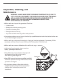
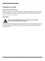
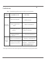
1
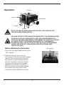
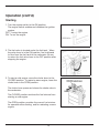
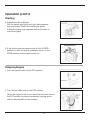
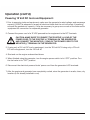
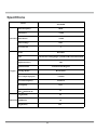
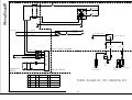
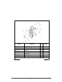
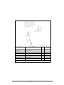
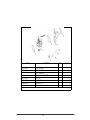
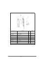
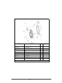
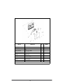
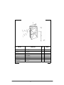
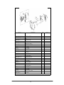
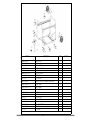
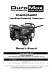
3500 3500 1-866-591-8921 3500WGenerator 7500WGenerator Topic Page SafetyGuidelines 3 Precautions al General elines d aGui 4 General ener l Parts recautions 12 Operation Battery 13 Inspection,CleaningandMaintenance Assembly 19 Installation Operation 20 n h Troublesooting nspection,CleaningandMaintenance 22 Specifications nstallation 2 3 D ce Wiringiagram Complia 24 GeneralPartsListing pe cifications 25 eneralPartsListing 29 WARNING!READANDUNDERSTANDALLSAFETYPRECAUTIONS INTHISMANUALBEFOREOPERATING.FAILURETOCOMPLYWITH INSTRUCTIONSINTHISMANUALCOULDRESULTINPERSONAL INJURY,PROPERTYDAMAGE,AND/ORVOIDINGOFYOUR WARRANTY.ALLPOWERAMERICAWILLNOTBELIABLEFORANY DAMAGEBECAUSEOFFAILURETOFOLLOWTHESEINSTRUCTIONS. 2 Safety Guidelines - Definitions This manual contains important information that you need to know and understand in order to protect YOUR SAFETY and to PREVENT EQUIPMENT PROBLEMS. The following symbols help you recognize this information. Please read the manual and pay attention to these sections. Save These Important Safety Instructions! Read and understand all of these safety instructions. Be sure to retain them for future use. WARNING! WARNINGS INDICATE A CERTAINTY OR STRONG POSSIBILITY OF PERSONAL INJURY OR DEATH IF INSTRUCTIONS ARE NOT FOLLOWED. CAUTION: CAUTIONS INDICATE A POSSIBILITY OF EQUIPMENT DAMAGE IF INSTRUCTIONS ARE NOT FOLLOWED. NOTE: NOTES GIVE HELPFUL INFORMATION WARNING! IMPROPER OPERATION OR MAINTENANCE OF THIS PRODUCT COULD RESULT IN SERIOUS INJURY AND PROPERTY DAMAGE. READ AND UNDERSTAND ALL WARNINGS AND OPERATING INSTRUCTIONS BEFORE USING THIS EQUIPMENT. WHEN USING AIR TOOLS, BASIC SAFETY PRECAUTIONS SHOULD ALWAYS BE FOLLOWED TO REDUCE THE RISK OF PERSONAL INJURY. 3 7500W Generator General Precautions WARNING! FAILURE TO FOLLOW THESE INSTRUCTIONS CAN RESULT IN SEVERE INJURY OR DEATH. CAUTION: FAILURE TO FOLLOW THESE INSTRUCTIONS CAN ALSO RESULT IN DAMAGE TO THE TOOL AND/OR THE ITEM YOU ARE WORKING ON. Carbon Monoxide When this tool is running, ensure that the area is well ventilated. Never run the engine in an enclosed area. Run the engine in an open area or with an exhaust evacuation system in an enclosed area. WARNING! THE EXHAUST CONTAINS POISONOUS CARBON MONOXIDE GAS THAT CAN CAUSE LOSS OF CONSCIOUSNESS AND MAY LEAD TO DEATH. Gasoline and Oil This product requires oil and fuel. Attempting to start the engine without oil will ruin the engine and void the warranty. Work in well ventilated area. Keep cigarettes, flames or sparks away from the work area or where gasoline is stored. WARNING! GASOLINE IS EXTREMELY FLAMMABLE AND IS EXPLOSIVE UNDER CERTAIN CONDITIONS. KEEP OUT OF REACH OF CHILDREN. • Gasoline fuel and fumes are flammable and potentially explosive. Use proper fuel storage and handling procedures. Always have multiple ABC class fire extinguishers nearby. • Keep the generator and surrounding area clean at all times. • Fuel or oil spills must be cleaned up immediately. Dispose of fluids and cleaning materials as per any local, state, or federal codes and regulations. Store oily rags in a covered metal container. • Never store fuel or other flammable materials near the generator. 4 Owner’s Manual General Precautions (cont’d) Gasoline and Oil (cont’d) • Do not smoke, or allow sparks, flames or other sources of ignition around the engine and fuel tank. Fuel vapors are explosive. • Keep grounded conductive objects, such as tools, away from exposed, live electrical parts and connections to avoid sparking or arcing. These events could ignite fumes or vapors. • Do not refill the fuel tank while the engine is running or while the engine is still hot. Do not operate the generator with known leaks in the fuel system • Excessive buildup of unburned fuel gases in the exhaust system can create a potentially explosive condition. This buildup can occur after repeated failed start attempts, valve testing, or hot engine shutdown. If this occurs, open exhaust system drain plugs, if equipped, and allow the gases to dissipate before attempting to restart the generator. • Use only engine manufacturer recommended fuel and oil. Hot Components WARNING! ENGINE AND EXHAUST SYSTEM PARTS BECOME VERY HOT AND REMAIN HOT FOR SOME TIME AFTER THE ENGINE IS RUN. WEAR INSULATED GLOVES OR WAIT UNTIL THE ENGINE AND EXHAUST SYSTEM HAVE COOLED BEFORE HANDLING THESE PARTS. Power Output This generator is not designed to power sensitive electronic equipment (including computers and medical devices) without the addition of an approved line conditioner, which is sold separately. CAUTION: ATTEMPTING TO POWER SENSITIVE ELECTRONIC EQUIPMENT WITHOUT THE USE OF AN APPROVED LINE CONDITIONER MAY CAUSE DAMAGE TO THE EQUIPMENT. ALL POWER AMERICA IS NOT RESPONSIBLE FOR ANY DIRECT OR INDIRECT DAMAGE CAUSED BY FAILURE TO USE AN APPROVED LINE CONDITIONER. 5 7500W Generator General Precautions (cont’d) Work Area • Keep your work area clean and well lit. Cluttered benches and dark areas invite accidents. • Do not operate power tools in explosive atmospheres, such as in the presence of flammable liquids, gases, or dust. Generators create sparks which may ignite the dust or fumes. • Keep bystanders, children, and visitors away while operating a generator. Provide barriers or shields as needed. Electrical Safety • Grounded tools must be plugged into an outlet properly installed and grounded in accordance with all codes and ordinances. Never remove the grounding prong or modify the plug in any way. Do not use any adapter plugs. • Grounding provides a low-resistance path to carry electricity away from the user in the event of an electrical malfunction. • Double insulated tools are equipped with a polarized plug where one blade is wider than the other. This plug fits in a polarized outlet only one way. If the plug does not fit fully in the outlet, reverse the plug. If it still does not fit, contact a qualified electrician to install a polarized outlet. Do not change the plug in any way. Double insulation eliminates the need for the three-wire grounded power cord and grounded power supply system. • Avoid body contact with grounded surfaces such as pipes, radiators, ranges, and refrigerators. There is an increased risk of electric shock if your body is grounded. • Do not expose generator to rain or wet conditions. Water entering a generator will increase the risk of electric shock. • Do not abuse the power cord. Keep power cords away from heat, oil, sharp edges, or moving parts. Replace damaged power cords immediately. Damaged power cords increase the risk of electric shock. • When operating a power tool outside, use an outdoor extension cord marked “W-A” or “W”. These extension cords are rated for outdoor use, and reduce the risk of electric shock. 6 Owner’s Manual General Precautions (cont’d) Electrical Safety (cont’d) • All connections and conduits from the generator to the load must only be installed by trained and licensed electricians, and in compliance with all relevant local, state, and federal electrical codes and standards, and other regulations where applicable. • The generator must be earth-grounded for fixed installations in accordance with all relevant electrical codes and standards before operation. • Do not attempt to connect or disconnect load connections while standing in water, or on wet or soggy ground. • Do not touch electrically energized parts of the generator and interconnecting cables or conductors with any part of the body, or with any non-insulated conductive object. • Connect the generator only to a load or electrical system (120 volt) that is compatible with the electrical characteristics and rated capacities of the generator. • Before servicing equipment powered by the generator, disconnect the equipment from its power input. • Keep all electrical equipment clean and dry. Replace any wiring where the insulation is cracked, cut abraded or otherwise degraded. Replace terminals that are worn, discolored, or corroded. Keep terminals clean and tight. • Insulate all connections and disconnected wires. • Guard against electric shock. Prevent body contact with grounded surfaces such as pipes, radiators, ranges, and refrigerator enclosures. Personal Safety • Stay alert. Watch what you are doing, and use common sense when operating a generator. Do not use generator while tired or under the influence of drugs, alcohol, or medication. A moment of inattention while operating generators may result in serious personal injury. • Dress properly. Do not wear loose clothing or jewelry. Contain long hair. Keep your hair, clothing, and gloves away from moving parts. Loose clothes, jewelry, or long hair can be caught in moving parts. 7 7500W Generator General Precautions (cont’d) Personal Safety (cont’d) • Avoid accidental starting. Make sure the power switch is in its “OFF” position, and disconnect the spark plug wire when not in use. • Remove adjusting keys or wrenches before turning the generator on. A wrench or a key that is left attached to a rotating part of the generator may result in personal injury. • Do not overreach. Keep proper footing and balance at all times. • Use safety equipment. Always wear eye protection. Wear ANSI approved safety impact eye goggles. Dust mask, non-skid safety shoes, hard hat, or hearing protection must be used for appropriate conditions. • Do not force the generator. Use the correct generator for your application. The correct generator will do the job better and safer at the rate for which it is designed. • Do not use the generator if the power switch does not turn it on or off. Any generator that cannot be controlled with the power switch is dangerous and must be replaced. Generator Use and Care Make sure the power switch is in its “OFF” position and disconnect the spark plug wire before making any adjustment, changing accessories, or storing the generator. Such preventive safety measures reduce the risk of starting the generator accidentally. Store idle generators out of reach of children and other untrained persons. Generators are dangerous in the hands of untrained users. Maintain generators with care. Do not use damaged generator. Tag damaged generators “Do not use” until repaired. Check for misalignment or binding of moving parts, breakage of parts, and any other condition that may affect the generator’s operation. If damaged, have the generator serviced before using. Many accidents are caused by poorly maintained generators. Use only accessories that are recommended by the manufacturer for your model. Accessories that may be suitable for one generator may become hazardous when used on another generator. 8 Owner’s Manual General Precautions (cont’d) Servicing Maintain labels and name plates on the generator and engine. These carry important information. If unreadable or missing, contact Pulsar Products Inc. immediately for a replacement. Generator service must be performed only qualified repair personnel. Service or maintenance performed by unqualified personnel could result in a risk of injury. When servicing a generator, use only identical replacement parts. Follow all appropriate instructions in this manual. Use of unauthorized parts or failure to follow maintenance instructions may create a risk of electric shock or injury. Heart Pacemakers WARNING! PEOPLE WITH PACEMAKERS SHOULD CONSULT THEIR PHYSICIAN(S) BEFORE USING THIS PRODUCT. ELECTROMAGNETIC FIELDS IN CLOSE PROXIMITY TO A HEART PACEMAKER COULD CAUSE INTERFERENCE TO OR FAILURE OF THE PACEMAKER. Installation • Ensure installation meets all applicable safety, and local and national electrical codes. Have installation performed by a qualified, licensed electrician and building contractor. • All electrical work, including the earth-ground connection, should be completed by a licensed electrician. • Any separate fuel storage or generator supply facility must be built or installed in full compliance with all relevant local, state, and federal regulations. • It is recommended to use the generator only in well ventilated outdoor areas. A running gasoline engine will generate carbon monoxide, a colorless, odorless gas that, if inhaled, can cause serious injury or death. If the generator is installed indoors, exhaust fumes must be piped out of the building using leak-free, heat resistant piping. Pipes and silencer should not use any flammable materials, nor should they be installed near the same. Generator exhaust fumes must be within legal imits and installation must always meet local building codes. 9 7500W Generator General Precautions (cont’d) Installation (cont’d) • If the generator is installed outdoors, it must be weatherproofed and should be soundproofed. It should not be run outdoors without protection to the generator and wiring conduit. • The generator weighs 105lbs (approx). Two or more people should assist when moving or lifting this product. Never lift the generator using the engine or alternator lifting lugs. Connect lifting equipment to the frame of the generator • Before lifting the generator, ensure the lift rigging and supporting structure are in good condition, and are rated to lift such a load. • Keep all personnel away from the suspended generator during relocating. • The supporting floor/ground surface should be level and strong enough to safely hold the weight of the generator. If the floor/grounded surface is not level, strong cross members should be placed under the full length of the generator frame at its low side. • For trailer installation, the generator should be mounted on the center point of the trailer, over the wheels. The trailer must be capable of supporting the weight of the generator and all contents (tools, etc.) • Install sound-and weather-proofing only when it is not raining or snowing to avoid trapping moisture within the generator’s area. Mechanical • Always make sure the power switch is in its “OFF” position. Disconnect the spark plug wire, and allow the engine to completely cool before carrying out maintenance. • Check for damaged parts. Before using the generator, any part that appears damaged should be carefully checked to determine that it will operate properly and perform its intended function. Check for alignment and binding of moving parts, any broken parts or mounting fixtures, and any other condition that may affect proper operation technician. • The generator is designed with guards for protection from moving parts. In any case, care must still be taken to protect personnel and equipment from other mechanical hazards when working around the generator. 10 Owner’s Manual General Precautions (cont’d) Mechanical (cont’d) • Do not operate the generator with safety guards removed. While the generator is running, do not attempt to reach around the safety guard for maintenance or any other reason. • Keep hands, arms, long hair, loose clothing, and jewelry away from moving parts. Be aware that when engine parts are moving fast they cannot be seen clearly. • Keep access doors on enclosures closed and locked when access is not required. • When working on or around the generator always wear protective clothing including ANSI approved safety gloves, safety eye goggles, and safety hat. • Do not alter or adjust any part of the generator that is assembled and supplied by the manufacturer. • Always follow and complete scheduled engine and generator maintenance. Chemicals • Avoid contact with hot fuel, oil, exhaust fumes, and hot solid surfaces. • Avoid body contact with fuels, oils, and lubricants used in the generator. If swallowed, seek medical treatment immediately. Do not induce vomiting if fuel is swallowed. For skin contact, immediately wash with soap and water. For eye contact, immediately flush eyes with clean water and seek medical attention. Noise • Prolonged exposure to noise levels above 68 DBA is hazardous to hearing. Always wear ANSI approved ear protection when operating or working around the generator when it is running. 11 Par t s enera l Parts General Fuel tank cap Frame Fuel tank Control Panel Choke lever Air filter Wheel Fuel valve Handel Oil dipstick Recoil starter Drain plug AC breaker AC breaker On/off switch Oil alert lamp DC terminal 12 120V outlet AC breaker Grounding terminal Owner’s Manual Operation Fuel tank k Lever Choke lever Control panel Fuel valve Pull start NOTE: THE PARTS LISTED ABOVE ARE HELPFUL FOR LOCATING THE CONTROLS MENTIONED BELOW. CAUTION: PRIOR TO FIRST USING THE GENERATOR, THE ENGINE MUST BE FILLED WITH OIL OF A HIGH QUALITY SAE 10W-30 GRADE ENGINE OIL. TO DO SO, UNSCREW AND REMOVE THE ENGINE’S OIL DIPSTICK LOCATED AT THE BOTTOM OF THE ENGINE CRANKCASE. FILL THE ENGINE’S CRANKCASE UNTIL THE OIL LEVEL IS LEVEL WITH THE UPPER MARKED LINE ON THE DIPSTICK. THEN SCREW THE DIPSTICK BACK INTO THE OIL FILL HOLE. Before Starting the Generator Fuel Tank Cap 1. Check that the engine power switch is in its “OFF” position. 2. Before the first use, remove the fuel tank cap and fill the fuel tank with unleaded gasoline. When fueling, be sure that the fuel strainer is in place. Replace the fuel tank cap. Thereafter, check the engine’s fuel gauge for the amount of unleaded gasoline in the fuel tank. If necessary, refill the fuel tank with unleaded gasoline; the generator must be turned off and cooled down before refilling the fuel tank. 13 Operation (cont’d) Starting 1. Turn the engine switch to the ON position. The engine switch enables and disables the ignition system. OFF: To stop the engine ON: To run the engine 2. The fuel valve is located under the fuel tank . When the valve lever is in the ON position, fuel is allowed to flow from the fuel tank to the carburetor. Be sur to return the fuel valve lever to the OFF position after stopping the engine. 3. To start a cold engine, move the choke lever to the CLOSED position. To restart a warm engine, leave the choke lever in the OPEN position. The choke lever opens and closes the choke valve in the carburetor. The CLOSED position enriches the fuel mixture from starting a cold engine. The OPEN position provides the correct fuel mixture for operation after starting, and for restarting a warm engine. 14 Operation (cont’d) Starting 4. Operate the Recoil Starter: Pull the starter grip lightly until you feel resistance, then pull briskly. Return the starter grip gently. Pulling the starter grip operates the recoil starter to crank the engine 5. If the choke lever has been moved to the CLOSED position to start the engine, gradually move it to the OPEN position as the engine warms up. Stopping Engine 1. Turn the engine switch to the OFF position. 2. Turn the fuel valve lever to the OFF position. When the engine is not in use, leave the fuel valve lever in the OFF position to prevent carburetor flooding and to reduce the possibility of fuel leakage. 15 Owner’s Manual Operation (cont’d) Powering 120 Volt AC Tools And Equipment: 1. Prior to powering tools and equipment, make sure the generator’s rated voltage, and amperage capacity (120VAC @ 27 AMPs) is adequate to supply all electrical loads that the unit will power. If powering exceeds the generator’s capacity, it may be necessary to group one or more of the tools and/or equipment for connection to a separate generator. CAUTION: ATTEMPTING TO POWER SENSITIVE ELECTRONIC EQUIPMENT WITHOUT THE USE OF AN APPROVED LINE CONDITIONER MAY CAUSE DAMAGE TO THE EQUIPMENT. ALL POWER AMERICA IS NOT RESPONSIBLE FOR ANY DIRECT OR INDIRECT DAMAGE CAUSED BY FAILURE TO USE AN APPROVED LINE CONDITIONER. 2. Once the generator is running, simply connect the power cords of 120 volt AC powered tools and equipment into the 120 volt AC dual outlets. NOTE: THE GENERATOR FEATURES AN AC NON-FUSE CIRCUIT BREAKER TO PROTECT THE AC CIRCUIT IN CASE OF AN OVERLOAD. SHOULD AN OVERLOAD OCCUR, THE BREAKER WILL “TRIP” TO ITS “OFF” POSITION, CAUSING THE GENERATOR TO AUTOMATICALLY SHUT DOWN. IN THIS CASE, REFER TO ABOVE IN THIS POSITION. THEN, RESET THE CIRCUITRY SYSTEM BY TURNING THE CIRCUIT BREAKER TO ITS “ON” POSITION. RESTART THE GENERATOR AND CONTINUE POWERING THE REMAINING TOOLS AND EQUIPMENT. 3. Disconnect Note: The Generator features an tools AC Non-Fuse Circuitfrom Breaker “OFF” position. TurnAC theduel fuel all electrical powered and equipment the generator's 120 volt valve to its “OFF” position. outlets. the engine and generator havetools completely cooled, store in safe,120 clean, 4. After Disconnect all electrical powered and equipment fromgenerator the generator’s volt dry AC duel outlets. location( if not already installed). 5. After the engine and generator have completely cooled, store generator in a safe, clean, dry location (if not already installed). 16 7500W Generator Operation (cont’d) Powering 12 Volt DC tools and Equipment: 1. Prior to powering tools and equipment, make sure the generator’s rated voltage, and amperage capacity (12VDC) is adequate to supply all electrical loads that the unit will power. If powering exceeds the generator’s capacity, it may be necessary to group one or more of the tools and/or equipment for connection to a separate generator. 2. Connect the power cord of a 12 VDC powered tool or equipment to the DC Terminals. CAUTION: MAKE SURE TO CONNECT THE POSITIVE (+) LEAD OF THE POWER CORD TO THE POSITIVE (+) TERMINAL ON THE GENERATOR, AND CONNECT THE NEGATIVE (-) LEAD OF THE POWER CORD TO THE NEGATIVE (-) TERMINAL ON THE GENERATOR. 3. If using only a 12V volt DC tool or equipment, turn the 120 volt AC If using only a 12V volt DC tool or equipment, turn the 120 volt AC 4. Start and run the engine as described above 5. When finished using the generator, turn the engine power switch to its “OFF” position. Turn the fuel valve to its “OFF” position. 6. Disconnect the electrical powered tools’ power cord from the generator’s DC terminals. 7. After the engine and generator have completely cooled, store the generator in a safe, clean, dry location (if not already installed in one). 17 Owner’s Manual Operation (cont’d) Spark Plug Service In order to service the spark plug, you will need a spark plug wrench (commercially available). Recommended spark plugs: NHSP LD F7TC. To ensure proper engine operation, the spark plug must be properly gapped and free of deposits. 1. Remove the spark plug cap. 2. Use a spark plug wrench to remove the spark plug. 3. Visually inspect the spark plug. Discard it if the insulator is cracked or chipped. Clean the spark plug with a wire brush if it is to be reused. 4. Measure the plug gap with a feeler gauge. 5. Check that the spark plug washer is in good condition. 6. After the spark plug is seated, tighten with a spark plug in by hand to prevent cross-threading. 7, After the spark plug is seated, tighten with a spark plug wrench to compress the washer. NOTE: THE SPARK PLUG MUST BE SECURELY TIGHTENED. AN IMPROPERLY TIGHTENED SPARK PLUG CAN BECOME VERY HOT AND COULD DAMAGE THE ENGINE. NEVER USE SPARK PLUGS WHICH HAVE AN IMPROPER HEAT RANGE. USE ONLY RECOMMENDED SPARK PLUS OR EQUIVALENT. 18 Owner’s Manual Inspection, Cleaning, and Maintenance WARNING! ALWAYS MAKE SURE THE ENGINE POWER SWITCH (2) IS IN ITS “OFF” POSITION. DISCONNECT THE SPARK PLUG WIRE FROM THE ENGINE. AND ALLOW SUFFICIENT TIME FOR THE ENGINE AND GENERATOR TO COMPLETELY COOL BEFORE PERFORMING ANY INSPECTIONS, MAINTENANCE, OR CLEANING. • Before each use, inspect the generator. Check for: - Loose screws - Misaligned or binding moving parts - Cracked or broken parts - Damaged electrical wiring - Any other condition that may affect safe operation. • If an engine problem occurs, have it checked by a qualified service technition before further use. Do not use damaged equipment. • Before each use, make sure the engine’s oil and gas levels are adequate. If necessary, fill the crankcase until the oil level is even with the oil hill hole and/or fill the fuel tank. • Before each use, remove all debris with a soft brush, rag, or vacuum. • Lubricate all moving parts using a premium quality, lightweight machine oil. • Every 50 hours of use, drain the old engine oil and replace with a high a high quality SAE 10W-30 grade engine oil. • Every 300 hours of use, have a qualified, certified technician perform thorough maintenance on the generator and engine. • For long term storage, either drain fuel into suitable container or add a fuel preservative/ stabilizer (not included) to prevent fuel breakdown. 19 Upper Level 7500W Generator Installation NOTE: PRIOR TO POWERING TOOLS AND EQUIPMENT MAKE SURE THE GENERATOR’S RATED VOLTAGE, WATTAGE AND AMPERAGE CAPACITY IS ADEQUATE TO SUPPLY ALL ELECTRICAL LOADS THAT THE UNIT WILL POWER. IF POWERING EXCEEDS THE GENERATOR’S CAPACITY, IT MAY BE NECCESSARY TO GROUP ONE OR MORE OF THE TOOLS AND/OR EQUIPMENT FOR CONNECTION TO A SEPERATE GENERATOR. Electrical and other permits may be required for the installation of emergency power systems. Investigate your local building and electrical codes before installing this unit. Installation must be completed by licensed contractors. WARNING! THE GENERATOR WEIGHS APPROXIMATELY 110 POUNDS. USE CARE AND THE PROPER LIFTING OR HOISTING EQUIPMENT WHEN MOVING IT TO THE INSTALLATION LOCATION. ALWAYS CONNECT HOIST LINES TO THE FRAME OF THE GENERATOR. General Location • Make sure to locate and install the generator outdoors where cooling air is readily available. • Install the generator so that the air inlets and outlets are not blocked by obstructions such as bushes, trees, or snow drifts. Locating it in the path of heavy winds or snowdrifts may require the placement of a barrier for protection. In normal weather conditions, the air vent should face the prevailing wind direction. • Install the generator on a concrete slab or other area where rain drainage or flood waters can not reach it. • Generator placement should allow four feet of access to all sides for maintenance. • Place the generator as close as possible to the electrical tools and equipment being powered to reduce the length of extension cords. 20 Owner’s Manual Installation (cont’d) Supporting and Mounting Mount the generator on a concrete slab capable of supporting the weight of the generator. The slab must extend on all sides beyond the frame by at least one foot. Contact a cement contractor for slab specifications if necessary. Attach the frame to the concrete slab using 3/8” diameter expansion anchor bolts (not supplied). Grounding NOTE: IT IS RECOMMENDED THAT ONLY A TRAINED AND LICENSED ELECTRICIAN PERFORM THIS PROCEDURE Connect a #6 AWG grounding wire (not included) from the ground connector (8) on the generator to a grounding rod (not included) that has been driven at least 24 inches deep into the earth. The grounding rod must be an earth-driven copper or brass rod (electrode) which can adequately ground the generator. 21 Troubleshooting Note: Troubleshooting problems may have similar causes and solutions. PROBLEM POSSIBLE CAUSE SOLUTION Is there fuel in the tank? The engine will not start Refill the fuel tank. Is there enough oil in the engine? Is the spark plug in good condition? at the AC outlets Readjust gap and dry the spark plug. Replace it if necessary. Is the fuel reaching the carburetor? No electricity Add the recommended oil. Clean the fuel sediment cup. Is the AC circuit breaker ON? Check the electrical appliance or equipment for any defects. Turn the AC circuit breaker ON. ·Replace the electrical appliance or equipment. ·Take the electrical appliance or equipment to an electrical shop for repair. If the engine still does not start, take the genera tor to an authorized our agent generator dealer. 22 Specifitions Model PG3500M Rated Frequency 60Hz Peak Power 3.5kW Generator Rated Power 3.0kW Rated Voltage 120V Power Factor 1 Model DJ170FD Type 4-stroke/air cooling/single cyclinder/OHV/horizontal shaft Displacement(cc) Engine 208 Ignition Model Transistorized Magneto Starting Model Recoil Start Max. Output (hp/rpm) 7.0/3600 Fuel Tank Capacity 15L/4Gal 0.6L Oil Capacity Continuous Work 15 Time half load (h) Length(inch) 24 Dimensions Width(inch) 18 Height(inch) 19.3 23 Breaker Wiring Diagra R R Breaker Breaker 5-20R W Y/G DC coil 1 Gr QVR1mm ² LB QVR1mm ² Bl QVR1mm ² + LB QVR1mm ² 2510 8A Bl QVR0.5mm ² Ignition Switch LED Bl QVR0.5mm ² Bl QVR0.5mm ² Control Box Diagram W QVR0.5mm ² W R Bu Bu R QVR0.5mm ² Bu QVR0.5mm ² Bu QVR0.5mm ² R QVR0.5mm ² Bl/W Bl A V R Bl Bl/W Oil Alert Unit W QVR0.5mm ² Generator Block Bl Black Br Brown O Bl/W QVR0.5mm ² Orange Br/R Brown/Red Engine Block Fuel Protector Spark Plug Ignition Coil Y/G Yellow/Green Bl/W Bu Blue LB Light Blue G Gr Gray Bl Black R W Black/White Green 1 A 新图 标记 处数 版本号 更改原因 签名 年月日 签名 年月日 签名 年月日 阶段标记 标准化 设计 A 制图 审核 共 张 校对 批准 24 WIRING DIAGRAM OF 120V GENERATOR SET Red White 重量 比例 第 张 重庆大江动力 设备制造有限公司 PG3500M ENGINE PARTS LISTING This list is provided for reference purposes only.All repairs and part replacement should be performed by a qualified technician. Some parts may not be available as single replacements. N PART NO. DJ170F-11100-HE GB276-89-6205 DJ168F-11014-A DJ168F-15100-A DJ168F-15001-A DJ168F-15002-A DJ168F-15003-A DJ168F-11004-A DJ168F-11005-A DJ168F-18200-C GBT16674-B6-16 DJ168F-18300-A GBT16674-B6-12 DJ168F-11039-A DJ168F-11400-A GBT16674-B6-20 DESCRIPTION CRANKCASE BEARING RADIAL BALL 6205 OIL SEAL Φ 25×Φ 41.25×6 SPEED REGULATING GEAR MOVING STAFF PLAIN WASHER PIN, LOCK DRAIN PLUG WASHER DRAIN PLUG OIL SENSOR ASSEMBLY BOLT FLANGE M6*16 OIL ALRAM BOLT FLANGE M6*12 Q CLIP WELDING COMP. WIND SHROUD BOLT FLANGE M6*20 25 Q'TY 1 1 1 1 1 1 1 2 2 1 2 1 1 1 1 1 REMARK N PART NO. DJ168FD-11001-A GB276-89-6205 DJ168F-11002-A DJ168F-11014-A DJ168F-11003-B DJ168F-11007-D GBT16674-B8-30 DESCRIPTION CRANKCASE COVER ASSEMBLY BEARING RADIAL BALL 6205 PIN Φ 8×14 OIL SEAL Φ 35×Φ 52×8 CRANKCASE GASKET DIPSTICK BOLT FLANGE M8*30 26 Q'TY 1 1 2 1 1 1 6 REMARK N PART NO. GBT16674-B6-12 DJ168F-11300-C DJ168F-11011-A DJ168F-18500-A GBT5789-B8-60 DJ168FD-14001-B DJ168F-14002-A DJ170FB-11200-AE DJ168F-11009-A DJ170F-11010-B DJ168F-11012-A DESCRIPTION BOLT FLANGE M6*12 CYCLINDER HEAD COVER ASSEMBLY GASKET, CYCLINDER HEAD COVER SPARK PLUG F7TC BOLT FLANGE M8*60 BOLT STUD M6*96 BOLT, STUD M8*35 CYLINDER HEAD ASSEMBLY PIN GASKET, CYLINDER HEAD AIR-LEADING COVER 27 Q'TY 6 1 1 1 4 2 2 1 2 2 1 REMARK N PART NO. DJ168F-12003-A DJ170FB-12001-B DJ170F-12002-A DJ170F-12200-BE DJ170F-12300-B DJ170FB-12100-BQE DESCRIPTION PISTON PIN CIR-CLIP PISTON PISTON PIN CONNECTING ROD ASSEMBLY PISTON RING SET CRANKSHAFT ASSEMBLY 28 Q'TY 2 1 1 1 1 1 REMARK N PART NO. DJ168F-13200-A DJ168F-13300-A DJ168F-13006-A DJ168F-13005-A DJ168F-13004-A DJ168F-13003-A DJ170F-13002-A DJ170F-13001-A DJ168F-13010-A DJ168F-13008-B DJ168F-13009-A DJ168F-13100-BE DESCRIPTION VALVE ROCKER ARM ASSEMBLY PUSH ROD GUIDE CAP VALVE RETURNER EXHAUST VALVE RETURNER INTAKE VALVE SPRING EXHAUST VALVE INTAKE VALVE CAP PUSH ROD TRAPPET LITTER VALVE CAMSHAFT ASSEMBLY 29 Q'TY 1 1 1 1 1 2 1 1 1 2 2 1 REMARK N PART NO. DJ168F-14027-A DJ170FB-14100-AE DJ168F-14005-B DJ168F-14004-A DJ168F-14003-B DJ168F-14008-A DJ168FD-14014-A DJ168FD-14007-C DESCRIPTION SPACER,CARBURETOR CARBURETOR ASSEMBLY GASKET, CARBURETOR CONNECTING BLOCK CARBURETOR GASKET INLET CLIP,FUEL LINE RUBBER ,FUEL LINE FUEL LINE 30 Q'TY 1 1 1 1 1 1 1 1 REMARK N PART NO. DJ168FD-14200-E DJ168FD-14204-B DJ168FD-14201-B DJ168FD-14203-E GB6177-N-6 GBT16674-B6-12 DJ168FD-11013-A DF2500H-14205-A DESCRIPTION AIR FILTER ASSEMBLY AIR FILTER CAP FILTER ELEMENT BOTTOM CAP,AIR FILTER NUT FLANGE M6 BOLT STUD M6*12 BRACKET,AIR FILTER TUBE BREATHER 31 Q'TY 1 1 1 1 2 1 1 1 REMARK N PART NO. GBT16674-B6-12 DJ168F-16100-F-116 DJ168F-16110-A DJ168F-16111-A DJ168F-16130-F-116 92140-B6-8 GBT97-W-6 DJ168F-16101-A-116 DESCRIPTION BOLT FLANGE M6*12 CASE COMP RECOIL STARTER STARTER ROPE STARTER COMP,RECOIL BOLT FLANGE M6*8 PLAIN WASHER RECOIL STARTER CASE 32 Q'TY 4 1 1 1 1 3 3 1 REMARK N PART NO. DJ168F-15008-A DJ168F-15006-A DJ168F-15007-A DJ168F-15004-A DJ168F-15005-A GB6177-N-6 DESCRIPTION FINE REGULATING SPRING C PULLING ROD BACK SPRING B SPEED REGULATING ARM LOCK BOLT NUT FLANGE M6 33 Q'TY 1 1 1 1 1 1 REMARK N PART NO. DJ168F-16205-A DJ168F-16000-A DJ168F-16002-A DJ168F-16200-AE GBT16674-B6-25 DJ168F-18100-C DESCRIPTION NUT M16*1.5 STARTING CUP IMPELLER FLYWHEEL ASSEMBLY BOLT FLANGE M6*25 IGNITION COIL ASSEMBLY 34 Q'TY 1 1 1 1 2 1 REMARK PG3500M GENERAL PARTS LISTING This list is provided for reference purposes only.All repairs and part replacement should be performed by a qualified technician. Some parts may not be available as single replacements. N PART NO. DJ168F-14008-A DF2500H-14302-A 92140-B6-25 DF2500H-14024-A DF2500H-14306-D DF2500H-14307-C DF2500H-14300-BY-116 DF3000H-14008-A DF3000H-14008-B DF3000H-14803-A 784810-NT DF6500H-34125-A DESCRIPTION CLIP,FUEL LINE FUEL COCK BOLT FLANGE M6*25 GASKET,FUEL TANK FUEL TANK CAP ASSEMBLY FUEL FILTER FUEL TANK ASSEMBLY CLIP,FUEL LINE CLIP,FUEL LINE CONNECTING PIPE ONE-WAY VALVE ASSEMBLY GASKET,ONE-WAY VALVE 35 Q'TY 1 1 4 4 1 1 1 1 1 1 1 1 REMARK N PART NO. GBT16674-B6-12 DF2500H-34106-A DF3000H-34100-QQ02 34203-004 34204-038 34204-039 34204-062 34208-021 34208-023 DESCRIPTION BOLT FLANGE M6*16 GASKET CONTROL PANEL ASSEMBLY SWITCH ASSEMBLY GROUNDING POST GROUNDING POST 120V DUPLEX OUTLETS THERMAL PROTECTOR THERMAL PROTECTOR 36 Q'TY 4 4 1 1 1 1 1 2 1 REMARK N PART NO. GBT93-LW-8 GB6170-N-8 DJ168F-14006-A DF3000H-14400-V GBT16674-B6-12 GBT16674-B8-16 DF3500H-14404-A DESCRIPTION SPRING WASHER NUT FLANGE M8 GASKET,EXHAUST MUFFER ASSEMBLY BOLT FLANGE M6*12 BOLT FLANGE M8*16 MUFFLER STAY 37 Q'TY 2 2 1 1 1 2 1 REMARK N PART NO. DESCRIPTION DF3000H-33100-BJ-20302 DF3000H-33120-BJ DF1800H-33001-A DF3000H-33110-BJ-20302 DF3800H-33002-A DF1800H-33005-C GBT97-W-8 GBT93-LW-8 DF3000H-33003-A DF3000H-33015-A DF1800H-33011-A GBT16674-B5-12 DF1800H-33006-A-116 GBT16674-B5-16 GBT93-LW-5 GBT862-CW-5 DF3000H-34216-B GBT16674-B6-12 GBT97-W-6 GBT93-LW-6 GBT862-CW-6 ALTERNATOR ASSEMBLY ROTOR CARBON BRUSH COMP. STATOR GROUNDING POST COMP. ALTERNATOR END BRACKET PLAIN WASHER SPRING WASHER BOLT M8*220 BOLT M6*165 VOLTAGE REGULATOR BOLT FLANGE M5*12 ALTERNATOR END COVER BOLT FLANGE M5*16 SPRING WASHER TOOTH TYPE WASHER GROUNDING WIRE BOLT FLANGE M6*12 PLAIN WASHER SPRING WASHER CONNECTING WIRE, FRAME DF3000H-31083-A DUST SHIELD 38 Q'TY 1 1 1 1 1 1 2 1 1 4 1 6 1 1 1 1 1 1 1 1 1 1 REMARK N PART NO. DF4000H-31016-A DF4000H-31060-A DF4000H-31058-A-117 GBT16674-B6-35 GB889-N-6 DF4000H-31014-A-117 92140-B6-40 DESCRIPTION RUBBER,HANDLE Q'TY 1 2 1 6 1 1 1 GB6177-N-6 HANDLE ASSEMBLY BOLT FLANGE M6*35 NUT M6 INSULATOR,HANDLE BOLT M6*40 NUT FLANGE M6 DF4000H-31204-A VIBRATION ISOLATION RUBBER,SQUARE FRAME 2 DF3000H-31020-D-117 SUPPORT,FRAME 2 RPG3000-31100-F-117 FRAME ASSEMBLY 1 GB6170-N-8 DF2500H-31202-A DF2500H-31201-A GB6177-N-8 GB6177-N-12 DF5000H-31017-C DF3000H-31018-E DF2500H-31019-B GBT97-W-16 NUT FLANGE M8 ISOLATOR B ISOLATOR A NUT FLANGE M8 NUT FLANGE M12 WHEEL WHEEL AXLE ASSEMBLY COTTER PIN FLAT WASHER 4 2 2 4 2 2 2 2 2 39 6 REMARK