1
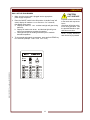
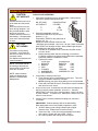
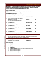
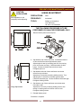
Place this chapter in the OVEN section of the equipment manual. WELLS MANUFACTURING 10 Sunnen Dr., St. Louis, MO 63143 telephone: 314-678-6314 fax: 314-781-2714 www.wellsbloomfield.com 903 OWNERS MANUAL VENTED CONVECTION OVEN MODEL M4200 Includes Installation Use & Care Programming Exploded View Parts List Wiring Diagram M4200 Convection Oven This instruction is for the exclusive use of licensees and employees of McDonalds Systems, Inc. IMPORTANT: DO NOT DISCARD THIS MANUAL This manual is considered to be part of the appliance and is to be given to the OWNER or MANAGER of the restaurant, or to the person responsible for TRAINING OPERATORS of this appliance. Additional manuals are available from your WELLS DEALER. THIS MANUAL MUST BE READ AND UNDERSTOOD BY ALL PERSONS USING OR INSTALLING THIS APPLIANCE. Contact your WELLS DEALER if you have any questions concerning installation, operation or maintenance of this equipment. p/n 2M-307323 Rev. G M903 140224 INTRODUCTION IMPORTANT: Use only factory authorized service parts. For factory authorized service, or to order factory authorized replacement parts, contact your Wells authorized service agency, or call: Thank You for purchasing this Wells Manufacturingappliance. Proper installation, professional operation and consistent maintenance of this appliance will ensure that it gives you the very best performance and a long, economical service life. This manual contains the information needed to properly install this appliance, and to use and care for the appliance in a manner that will ensure its optimum performance. Wells Bloomfield, LLC 10 Sunnen Dr., St. Louis MO 63143 USA Service Dept. phone: (877) 242-0270 fax: (314) 781-2714 M903 2M-307323 Owners Manual M4200/M4200EU xi TABLE OF CONTENTS GENERAL OPERATION AGENCY LISTING INFORMATION WARRANTY PRECAUTIONS & GENERAL INFORMATION SPECIFICATIONS INSTALLATION FEATURES & OPERATING CONTROLS OVEN FEATURES SMART CONTROLLER OPERATION QUICK-GLANCE OPERATING GUIDE DAILY SET-UP COOK CYCLE OPERATION 1 2 3 4 5 8 10 12 13 14 PROGRAMMING IMPORTANT: Programming to be performed by Qualified Personnel ONLY! ENTER PROGRAMMING MODE CHANGE PROGRAMMED SETTINGS ENABLING SCRATCH BISCUIT BUTTON (#6) INSTRUCTIONS TO CHANGE COOKIE SETTINGS INSTALL OPERATING SYSTEMS SOFTWARE TRANSFER MENUS FROM CARD TO OVEN TRANSFER MENUS FROM OVEN TO CARD DEFAULT SETTINGS PROGRAMMING MAINTENANCE M903 2M-307323 Owners Manual M4200/M4200EU SERVICE 15 16 18 19 20 21 21 22 CLEANING INSTRUCTIONS TROUBLESHOOTING SUGGESTIONS PREVENTATIVE MAINTENANCE TEMPERATURE CALIBRATION HINGE ADJUSTMENT 23 25 26 27 EXPLODED VIEW and PARTS LIST WIRING DIAGRAM M4200 208V M4200 240V M4200-3S-240 PARTS & SERVICE CUSTOMER SERVICE DATA FORM 28 32 33 34 37 37 AGENCY LISTING INFORMATION This appliance conforms to NSF Standard 4 for sanitation only if installed in accordance with the supplied Installation Instructions and maintained according to the instructions in this manual. M4200 (domestic) ovens are for 208V and 240V. and M4200EU (European) ovens comply with listed under UL File E6070 standards for 380-415V 3NAC 1 STD 4 E6070 E6070 LIMITED WARRANTY STATEMENT The M4200 Convection Oven manufactured by WELLS for sale to McDonald's, Inc. is warranted against defects in materials and workmanship for a period of two years from the date of installation (as indicated by the installation punch-tag on the equipment), and is for the benefit of the original purchaser: All other equipment manufactured by WELLS for sale to McDonald's, Inc. is warranted against defects in materials and workmanship for a period of one year from the date of installation (as indicated by the installation punch-tag on the equipment), and is for the benefit of the original purchaser: The prices charged by Wells for its products are based upon the limitations in this warranty. Seller’s obligation under this warranty is limited to the repair of defects without charge by a Wells Authorized Service Agency or one of its subagencies. This service will be provided on customer’s premises for non-portable models. Portable models (a device with a cord and plug) must be taken or shipped to the closest Authorized Service Agency, transportation charges prepaid, for services. In addition to restrictions contained in this warranty, specific limitations are shown below (Additional Warranty Exclusions). Authorized Service Agencies are located in principal cities. This warranty is valid in the United States & Canada and void elsewhere. Please consult your classified telephone directory or your food service equipment dealer; or, for information and other details concerning warranty, write to: THE FOREGOING OBLIGATION IS EXPRESSLY GIVEN IN LIEU OF ANY OTHER WARRANTIES, EXPRESSED OR IMPLIED, INCLUDING ANY IMPLIED WARRANTY OF MERCHANTABILITY OR FITNESS FOR A PARTICULAR PURPOSE, WHICH ARE HEREBY EXCLUDED. WELLS SHALL NOT BE LIABLE FOR INDIRECT, INCIDENTAL OR CONSEQUENTIAL DAMAGES OR LOSSES FROM ANY CAUSE WHATSOEVER. Wells 10 Sunnen Dr., St. Louis MO 63143 USA phone (314) 678-6314 or fax (314) 781-2714 for information and other details concerning warranty. This warranty is void if it is determined that upon inspection by an Authorized Service Agency that the equipment has been modified, misused, misapplied, improperly installed, or damaged in transit or by fire, flood or act of God. It also does not apply if the serial nameplate has been removed or unauthorized service personnel perform service. SERVICE POLICY AND PROCEDURE GUIDE and ADDITIONAL WARRANTY EXCLUSIONS 1. 2. 3. 5. 6. cleaning schedules, are customer responsibility. Those miscellaneous adjustments noted are customer responsibility. Proper attention to preventative maintenance and scheduled maintenance procedures will prolong the life of the appliance. 7. Travel mileage is limited to fifty (50) miles from an Authorized Service Agency or one of its sub-service agencies. 8. All labor shall be performed during regular working hours. Overtime premium will be charged to the buyer. 9. All genuine Wells replacement parts are warranted for ninety (90) days from date of purchase on nonwarranty equipment. This parts warranty is limited only to replacement of the defective part(s). Any use of non-genuine Wells parts completely voids any warranty. 10. Installation, labor, and job check-outs are not considered warranty and are thus not covered by this warranty. 11. Charges incurred by delays, waiting time or operating restrictions that hinder the service technician’s ability to perform service are not covered by warranty. This includes institutional and correctional facilities. SHIPPING DAMAGE CLAIM PROCEDURE NOTE: For your protection, please note that equipment in this shipment was carefully inspected and packaged by skilled personnel before leaving the factory. Upon acceptance of this shipment, the transportation company assumes full responsibility for its safe delivery. IF SHIPMENT ARRIVES DAMAGED: 1. VISIBLE LOSS OR DAMAGE: Be certain that any visible loss or damage is noted on the freight bill or express receipt, and that the note of loss or damage is signed by the delivery person. 2. FILE CLAIM FOR DAMAGE IMMEDIATELY: Regardless of the extent of the damage. 3. CONCEALED LOSS OR DAMAGE: if damage is unnoticed until the merchandise is unpacked, notify the transportation company or carrier immediately, and file “CONCEALED DAMAGE” claim with them. This should be done within fifteen (15) days from the date the delivery was made to you. Be sure to retain the container for inspection. Wells cannot assume liability for damage or loss incurred in transit. We will, however, at your request, supply you with the necessary documents to support your claim. 2 M903 2M-307323 Owners Manual M4200/M4200EU 4. Resetting of safety thermostats, circuit breakers, over load protectors, and/or fuse replacements are not covered by this warranty unless warranted conditions are the cause. All problems due to operation at voltages or phase other than specified on equipment nameplates are not covered by this warranty. Conversion to correct voltage and/or phase must be the customer’s responsibility. All problems due to electrical connections not made in accordance with electrical code requirements and wiring diagrams supplied with the equipment are not covered by this warranty. Replacement of items subject to normal wear, to include such items as knobs, light bulbs; and, normal maintenance functions including adjustments of thermostats, adjustment of micro switches and replacement of fuses and indicating lights are not covered by warranty. Damage to electrical cords and/or plug due to exposure to excessive heat are not covered by this warranty. Full use, care, and maintenance instructions supplied with each machine. Noted maintenance and preventative maintenance items, such as servicing and PRECAUTIONS AND GENERAL INFORMATION This appliance is intended for use in commercial establishments only. This appliance is intended to prepare food for human consumption. No other use is recommended or authorized by the manufacturer or its agents. Operators of this appliance must be familiar with the appliance use, limitations and associated restrictions. Operating instructions must be read and understood by all persons using or installing this appliance. Cleanliness of this appliance is essential to good sanitation. Read and follow all included cleaning instructions and schedules to ensure the safety of the food product. Disconnect this appliance from electrical power before performing any maintenance or servicing. DO NOT submerge this appliance in water. This appliance is not jet stream approved. Do not direct water jet or steam jet at this appliance, or at any control panel or wiring. Do not splash or pour water on, in or over any controls, control panel or wiring. Do not wash floor around this appliance with water or steam jet. Exposed surfaces of this appliance can be hot to the touch and may cause burns. Do not operate this appliance if the control panel is damaged. Do not operate this appliance if the keypad section of the control panel is torn or broken. Call your Authorized Wells Service Agent for service. The technical content of this manual, including any wiring diagrams, schematics, parts breakdown illustrations and/or adjustment procedures, is intended for use by qualified technical personnel. M903 2M-307323 Owners Manual M4200/M4200EU Any procedure which requires the use of tools must be performed by a qualified technician. This manual is considered to be a permanent part of the appliance. This manual and all supplied instructions, diagrams, schematics, parts breakdown illustrations, notices and labels must remain with the appliance if it is sold or moved to another location. This appliance is made in the USA. Unless otherwise noted, this appliance has American sizes on all hardware. 3 WARNING: SHOCK HAZARD All servicing requiring access to non-insulated electrical components must be performed by a factory authorized technician. DO NOT open any access panel which requires the use of tools. Failure to follow this warning can result in severe electrical shock. CAUTION: RISK OF DAMAGE DO NOT connect or energize this appliance until all installation instructions are read and followed. Damage to the appliance will result if these instructions are not followed. CAUTION: HOT SURFACE Exposed surfaces can be hot to the touch and may cause burns. SPECIFICATIONS DIMENSIONS APPLIANCE OVEN CAVITY Wide 30-1/8” (765mm) 14-3/8” (365mm) Deep 25-1/4” (641mm) oven only 27-7/8” (682mm) incl. handle 21” (533mm) High 25-1/8” (638mm) oven only 34” (863mm) incl. prep-top\ and casters 20” (508mm) Door Swing 20" (508mm )radius ELECTRICAL M4200 208 VAC 3ø 60Hz 8750 kW total 21 Amps per leg M4200 240 VAC 3ø 60Hz 8750 kW total 21 Amps per leg M4200-3S-230 380-415V 3NAC 5-/60Hz 8750 kW total 11.7 Amps 11.7 Amps 11.7 Amps 1.0 Amps L1 L2 L3 N Note: Shipped from the factory 3 phase with pin-and-sleeve electrical plug. Unit is NOT approved for conversion to single phase. M903 2M-307323 Owners Manual M4200/M4200EU 4 INSTALLATION UNPACKING & INSPECTION Carefully remove the appliance from the carton. Remove all protective plastic film, packing materials and accessories from the Appliance before connecting electrical power or otherwise performing any installation procedure. Carefully read all instructions in this manual and the Installation Instruction Sheet packed with the appliance before starting any installation. Read and understand all labels and diagrams attached to the appliance. Carefully account for all components and accessories before discarding packing materials. Store all accessories in a convenient place for later use. COMPONENTS 3 ea. 2 ea. 1 ea. LITERATURE PACKAGE OPTIONAL ACCESSORIES 21330 21445 23035 21342 Caster Set Prep Top Kit Venting Duct Assembly Kit (single oven) Stacking kit for double ovens SERVICE TECHNICIAN INSTALLATION NOTES M903 2M-307323 Owners Manual M4200/M4200EU WARNING: RISK OF INJURY Installation procedures must be performed by a qualified technician with full knowledge of all applicable electrical and plumbing codes. Failure can result in personal injury and property damage. OVEN RACKS RACK SUPPORTS FAN BAFFLE ACCESSORIES 1 ea. NOTE: DO NOT discard the carton or other packing materials until you have inspected the appliance for hidden damage and tested it for proper operation. Refer to SHIPPING DAMAGE CLAIM PROCEDURE on the inside front cover of this manual. 1. Installation and start up should be performed by an authorized installation company. Installer must record installation particulars on the CUSTOMER SERVICE DATA form on page 33 of this manual. 2. Verify that this equipment installation is in compliance with the specifications listed in this manual and with local code requirements. 5 IMPORTANT: It is the RESPONSIBILITY OF THE INSTALLER to check with the AUTHORITY HAVING JURISDICTION, in order to verify compliance with local codes and ordinances for THIS SPECIFIC EQUIPMENT INSTALLATION. INSTALLATION (continued) WARNING: SHOCK HAZARD All servicing requiring access to non-insulated electrical components must be performed by a factory authorized technician. DO NOT open any access panel which requires the use of tools. Failure to follow this warning can result in severe electrical shock. NOTE: Oven is shipped with biscuit baking adapter plate attached to rear panel. If oven is used exclusively for bread products (bread, pies, etc.), DO NOT remove adapter. If oven is used for proteins, install optional external vent kit # WS-505504. Protein requires additional venting to decrease release of cooking vapors when opening the door. 2. CURB or COUNTER MOUNTING a. Setup the appliance only on a firm, level, non-combustible surface. Verify local codes for requirements. Concrete, tile, terrazzo or metal surfaces are recommended. Metal over combustible material may not meet code for non-combustible surfaces. b. Appliance is approved for installation with zero clearance at bottom. c. Recommend at least 3” clearance on sides and back to allow adequate air flow. 3. INSTALLING OPTIONAL CASTERS (NOTE: casters are not provided and must be purchased separately: kits 5F-21372 & 5F-21373.) a. Install casters, one on each corner of the appliance, in the holes provided. Locking casters must be installed on the FRONT of the appliance. b. Set up the appliance only on a firm, level, non-combustible surface. Verify local codes for requirements. Concrete, tile, terrazzo or metal surfaces are recommended. Metal over combustible material may not meet code for non-combustible surfaces. c. LEVELING: Verify that the appliance sits firmly on all four casters when in its normal operational position. With a level, check that the appliance is level front-to-back and side-to-side. 4. INSTALLING OPTIONAL LEGS (NOTE: Legs are not provided and must be purchased separately: (Kit: 5F-22829, set of 2) a. Install adjustable legs, one on each corner of the appliance, in the holes provided. b. Set up the appliance only on a firm, level, non-combustible surface. Verify local codes for requirements. Concrete, tile, terrazzo or metal surfaces are recommended. Metal over combustible material may not meet code for non-combustible surfaces. c. LEVELING: Verify that the appliance sits firmly ON ALL FOUR LEGS. With a spirit level, check that the appliance is level front-to-back and side-to-side. 5. OTHER OPTIONAL KITS a. Kit 5F-21445 Prep Top allows the top of the M4200 to be used as an NSF 4-compliant work surface. b. Kit WS-23035 Oven Stacking Kit allows M4200 units to be stacked 2-high. The kit provides extended ducting for the vent system. c. Kit WS-505504 - Convert to protein oven. 6 M903 2M-307323 Owners Manual M4200/M4200EU Vent Duct Installation EQUIPMENT SET-UP 1. IF CONVECTION OVEN IS TO BE USED FOR PROTEINS, INSTALL EXTERNAL DUCT a. Remove 2 screws at each end of adapter plate on back of oven. b. Loosen 2 screws at bottom of adapter plate. Remove adapter plate. c. Slide bottom flange of vent duct over the two loosened screws. d. Install four and tighten screws at ends of vent duct, then tighten bottom screws. INSTALLATION (continued) DANGER: SHOCK HAZARD ELECTRICAL CONNECTIONS MUST BE MADE BY A LICENSED ELECTRICIAN Electrical shock will cause death or serious injury. Refer to the nameplate on the front of the appliance. • Verify the ELECTRICAL SERVICE POWER. • CAUTION: Voltage and phase must match the nameplate specifications, and electrical service amps must meet or exceed the specifications listed on page 1. IMPORTANT: The appliance is shipped from the factory wired for 3-phase (3ø) electrical service. This appliance is not approved for 1ø operation. Conversion of this appliance to single-phase operation will void the warranty. M4200 (domestic) field wiring must be no less than 10 AWG 4 conductor solid copper wire, rated for at least 90ºC. NOTE: Wire gauge, insulation type and temperature rating , as well as type, size and construction of conduit, must meet or exceed applicable specifications of local codes and of the National Electrical Code. This appliance is equipped with a Hubbell L430P9 plug, which must be plugged into a matching Hubbell L430R9 receptacle. The ground lug of the receptacle must be connected to a suitable building ground. M4200-EU (European) field wiring must have a minimum cross-sectional area of 1.5mm2. M903 2M-307323 Owners Manual M4200/M4200EU ! IMPORTANT: An approved all pole power disconnect switch, With at least 3 mm contact gap, must be supplied and installed in the fixed wiring in an accessible location (close proximity to the appliance) by a licensed electrician. NOTE: Strain relief supplied loose is for metal conduit connection. For flexible power cords an approved strain relief fitting must be supplied by others. EU INSTALLATION INSTRUCTIONS: 1. Using a screwdriver, remove terminal access panel located behind front door marked: NOTICE - REMOVE THIS PANEL FOR TERMINAL BLOCK 2. Knock out the appropriate hole plug located on enclosure panel and connect conduit strain relief. 3. Thread supply leads through strain relief • Connect supply power lines to terminals marked: L1, L2, L3 • • Connect the neutral line terminal marked: N Connect green-with-yellow-stripe lead to ground lug marked RISK OF DAMAGE DO NOT connect or energize this appliance until all installation instructions are read and followed. Damage to the appliance will result if these instructions are not followed. CAUTION: SHOCK HAZARD The ground lug of this appliance must be connected to a suitable building ground. IMPORTANT: Contact a licensed electrician to install and connect electrical power to the appliance. IMPORTANT: Damage due to being connected to the wrong voltage or phase is NOT covered by warranty. IMPORTANT PROGRAMMING NOTE: This oven is pre-programmed from the factory and normally does not require programming adjustments. EU Connections SUPPLY LINE 3 L3 SUPPLY LINE 2 L2 SUPPLY LINE 1 L1 4. Secure all connections and reinstall terminal access cover. NEUTRAL 5. “Equal Potential” grounding screw is located at rear of frame, marked Remove screw and secure an appropriate grounding wire with terminal. GROUND N IL2357 7 FEATURES & OPERATING CONTROLS M4200 CONVECTION OVEN FEATURES M903 2M-307323 Owners Manual M4200/M4200EU 8 M903 2M-307323 Owners Manual M4200/M4200EU FEATURES & OPERATING CONTROLS (continued) ITEM DESCRIPTION FUNCTION A. OPTIONAL PREP TOP Allows top of oven to be used as a work surface B. OVEN TOP Covers and protects top insulation C. OVEN DOOR Covers and provides access to oven cavity D1. DOOR HANDLE D2. DOOR STRIKER & LATCH Safe hand hold to open or close oven. Striker and door- mounted latch hold oven door closed E. ACCESS PANEL Covers and provides access to fan motor and electric connections and controls F1. COOLING FAN INLET F2. COOLING LOUVERS Provides air circulation for cooling. DO NOT spray or pour water into cooling fan inlet or louvers G. POWER CORD (not provided on EU models) Supplies power from receptacle to oven H. CORD HANGER Provides storage for cord when moving oven I. EXTERNAL CAVITY VENT Cooking fumes are vented here J. OPTIONAL FRONT CASTERS Allow oven to be easily moved; locking to stabilize oven when in position K. OPTIONAL REAR CASTERS Allow oven to be easily moved. L. POWER FUSES Protect electrical circuits from overload M. DATA PLATE Provides manufacturer, model and serial number information. Also, provides electrical specifications and requirements N. POWER PLUG (not provided on EU models) Plugs into power receptacle P. CARD READER Reads menu card Q. MENU CARD Contains default information; used to reprogram smart controller with default settings in the event of program errors R. ON/OFF SWITCH Energizes appliance S. SMART CONTROLLER Controls cooking times and temperatures; selectable pre-programmed settings. DO NOT spray or pour water into controller T. BEEPER Audible indicator for alarms, end-of-cycle, etc. U. RACK SUPPORTS Hold cooking racks V. PRODUCT RACK Holds product to be cooked W. HEATING ELEMENTS Provide cooking heat when energized X. FAN Circulates heated air during cooking Y. FAN BAFFLE Covers fan, also provides mounting for right rack support 9 FEATURES & OPERATING CONTROLS (continued) SMART CONTROLLER M903 2M-307323 Owners Manual M4200/M4200EU 10 FEATURES & OPERATING CONTROLS (continued) BUTTON DESCRIPTION / FUNCTION VIEW TEMP View current temperature & setpoint temperature by pressing and holding 3 seconds. When baking multiple products can view time remaining. In program mode arrow indicates cursor will move to the right when entering data. PROG Press and hold for 5 seconds to enter into program mode. After entry and pressing PROG button can access the following areas. When asked for password, enter 9793. 1) Temp Cal - - Not password protected. Used for calibrating temperature 2) View menu - - Not password protected. In this mode can view each product setting by pressing the appropriate button. Cannot edit or change settings in this mode. 3) Edit menu - - Password protected (Authorized Personnel Only). In this mode can view and change settings, names, alarms, etc. in buttons 1 – 0 4) Service menu - - Password protected (Authorized Personnel Only). Contains the following information a) Unit ID # f) Rise Time 10:00 b) Scale ºF g) Detect Current YES c) Temp CompYES h) Time (clock, real time) d) Energy Saver NO e) Default Menu 5) Transfer menu - - Password protected (Authorized Personnel Only). Contains the following functions; a) Read Menu Card Controller will read information from the card b) Write Menu Card Controller will transfer information to the card c) Restore Menu Restores default menu settings (Use Menu Card) d) Restore Systems Restore default operating systems settings (Use System Card) 6) Systems info - - Not password protected. Contains the following information used to determine system versions and updates. a) Model # b) Bios Version c) O/S Version (operating systems) d) Default Menu M903 2M-307323 Owners Manual M4200/M4200EU NOTE: Program button is used as the enter key for accepting data and / or moving to the next function. START Actuates the timing cycle for baking. In programming mode used to exit and save Buttons 0 – 9 Used to select stored menu items. In programming mode also used to enter alpha sequences to change or enter product names. Buttons 2 & 8 Select menu items. Also used in the programming mode for scrolling up or down numerically for temperature calibration, and changing no to yes or vice versa. UTILITY 1) Contains cool down function. 2) Used to switch between dayparts by holding UTILITY button for 3 seconds then pressing PROG. 3) In program mode arrow function is used to move cursor to the left CANCEL 1) Used to cancel alarms. 2) In program mode used to exit out without saving. 3) Used to cancel a bake cycle. Press VIEW to display desired bake cycle, then press CANCEL to cancel that bake cycle. IMPORTANT PROGRAMMING NOTE: This oven is pre-programmed from the factory and does not require programming adjustments under normal circumstances. 11 QUICK-GLANCE OPERATING GUIDE WELLS CONVECTION OVEN OPERATING INSTRUCTIONS (SEE OPERATION SECTION OF OWNERS MANUAL FOR MORE INFORMATION) START-UP AND NORMAL OPERATION ACTION DISPLAY WILL READ 1. Verify the oven is plugged into proper outlet. 2. Turn power switch to “ON” position. WELLS BLOOMFIELD <for 3 seconds> 3. Oven will begin to heat up to a pre-set temperature of 375ºF. TOO COOL NOTE: Controller display will read “TOO COOL” until oven reaches pre-set temperature of 375ºF. During initial heat up, oven will not operate until “OVEN READY” is displayed. When “OVEN READY” is displayed, have product ready to put into oven. 4. Open door, position product on proper shelf and close door. OVEN READY 5. Press correct product button Press “START” button. EXAMPLE: BISCUITS 3:00 6. At end of a cook cycle audible alarm will sound. Alarm will automatically shut off when door is opened or CANCEL button is pushed. BISCUITS REMOVE 7. Remove product and close door OVEN READY 8. Repeat numbers 4, 5, 6 and 7 for additional cook cycles. Be sure correct menu option is selected and displayed. Always push “START” button to begin cook cycle. ACTION DISPLAY WILL READ 1. When last product is done for the day open door of oven and let it remain open. 2. Press “UTILITY” button. FAST COOL MODE 3. Press “START” button. Fan will start COOL DOWN 4. Allow cool-down process for a minimum time of 3 – 5 minutes. 5. Press power switch to “OFF” position. Interior of oven can then be safely cleaned. 12 M903 2M-307323 Owners Manual M4200/M4200EU SHUT-DOWN PROCEDURE OPERATION DAILY SET-UP PROCEDURES CAUTION: 1. Make sure the power cord is plugged into the appropriate power supply receptacle. HOT SURFACE 2. Place the ON/OFF switch in the ON position. A double "beep" will sound, display will read WELLS BLOOMFIELD for 3 seconds, then display oven status: a. Display will read TOO COOL and the heat light will glow during warm-up. b. Display will read OVEN READY and the heat light will go out when oven temperature reaches the setpoint. c. Heat light will cycle as heating elements cycle to maintain desired temperature. M903 2M-307323 Owners Manual M4200/M4200EU 3. To view actual and setpoint temperature, press and hold TEMP key for 5 seconds (example: TEMP 340F SET 375F). 13 Exposed surfaces can be hot to the touch and may cause burns. Oven door will be hot to the touch during operation. Use the provided handle to open and close oven door. NOTE: A "beep" will sound each time a key is pressed. OPERATION (continued) CAUTION: COOK CYCLE OPERATION HOT SURFACE 1. Slide racks of product into oven as appropriate. Shelf positions required for quality baked products are: Exposed surfaces can be hot to the touch and may cause burns. Oven door will be hot to the touch during operation. Use the provided handle to open and close oven door. Product and trays will be hot after baking. Use appropriate oven mitt to remove product or trays. CAUTION: CUT HAZARD Fan will be running during cool-down. Avoid reaching into the oven while oven is in cool-down mode. Fan blades are sharp and can cause lacerations. NOTE: Convection fan will be running at all times the power switch is ON and the oven door is closed. RACK POSITION UTILIZED 5 2&8 2, 5 & 8 2. Press the appropriate menu key. Press button ONCE for any full tray of product (1, 2, 3). Press button TWICE for any partial tray of product (1/2, 1/4, …). Display will show selected menu item and associated time (example: BISCUITS 03:00). Within 5 seconds, press START key to begin cooking. Start indicator light will glow and display time will begin cook timer. a. If START is not pressed within 5 seconds, controller returns to OVEN READY. b. Display shows product and time remaining on cook timer. To display multiple cook cycles, press VIEW button repeatedly. Partial tray readout is <BISCUITS PAR> c. Typical menu items for full trays for partial trays 1. BISCUITS BISCUITS PAR 2. BAGELS BAGELS PAR 3. PIES PIES PAR 4. COOKIES COOKIES PAR 5. McGRIDDLES McGRIDDLES PAR 6. SCR BISCUITS 3. If necessary to interrupt cook cycle: a. Timer pauses if door is opened during cook cycle. Timer will resume countdown when door is closed. NOTE: Opening oven door during baking is not recommended. b. Press and hold CANCEL key for 5 seconds to cancel countdown and return to OVEN READY. 4. At end of cook cycle, a continuous tone will sound and display will advise to remove product (example: BISCUITS REMOVE). IMPORTANT: Use oven mitt to remove product. Open oven door or press CANCEL to silence tone. When door is closed, oven will return to OVEN READY. 5. Cooling Timer is currently enabled for baking pies, and set to 10 minutes. IMPORTANT: Product and trays will be hot after baking. Wear appropriate oven mitt to handle hot product or trays. a. At end of baking cycle cooling indicator light will glow. Remove trays. Products are to remain on trays. b. Close oven door. Oven timer will automatically sound after time expires. Display will read <PIES COOL>. c. Do not box product until cooling time has expired. 14 M903 2M-307323 Owners Manual M4200/M4200EU NOTE: Menu items are subject to change at the discretion of McDonalds Management. NO. OF PANS OF PRODUCT 1 2 3 PROGRAMMING INSTRUCTIONS IMPORTANT: This oven is pre-programmed from the factory and does not require programming adjustments under normal circumstances. Any programming changes must be performed by qualified persons only. ENTER PROGRAM MODE NOTE: Oven must be turned ON. No cooling timer or bake cycle can be active. Special Button Functions: Scroll through the options by pressing the PROG button: # 2 and #8 allows scrolling up or down; and, changes from yes or no 1) ACTION DISPLAY WILL READ To enter programming mode, press and hold PROG button for 5 seconds TEMP CAL NO VIEW MENU ITEM NO This option allows temperature calibration 2) Press PROG button This option allows viewing programmed values of menu items 3) Press PROG button EDIT MENU NO This option allows changing programmed values of menu items 4) Press PROG button SERVICE MENU NO This option allows changes to temperature scale and to set real-time clock 5) Press PROG button TRANSFER MENU NO This option allows history upload, read menu card, write menu card and restore defaults M903 2M-307323 Owners Manual M4200/M4200EU 6) Press PROG button SYSTEM INFO NO This option allows viewing of controller model number, BIOS program number and version, operating system (O/S) number and version, and default menus To EXIT PROGRAM MODE: Press CANCEL button two (2) times. Controller will revert to RUN mode OVEN READY Button Designation: #1 #2 #3 #4 #5 #6 #7 #8 #9 #0 BISCUITS BAGELS PIES COOKIES McGRIDDLES SCRATCH BISCUITS (disabled where ready to bake biscuits are used) Disabled for future menu options Disabled for future menu options Disabled for future menu options Disabled for future menu options 15 PROGRAMMING INSTRUCTIONS (continued) IMPORTANT: This oven is pre-programmed from the factory and does not require programming adjustments under normal circumstances. Any programming changes must be performed by qualified persons only. CHANGE SETTINGS for name, cooking time, cooking temperature and cooling time NOTE: Cannot go into edit or view program mode when cooling timer s activated or when in a bake cycle. 1) ACTION DISPLAY WILL READ Enter programming mode, press and hold PROG button for 5 seconds CAL TEMP NO 2) Press PROG button until EDIT menu is reached EDIT MENU ITEM NO 3) Press #2 or #8 button to select YES EDIT MENU YES 4) Press PROG button PASSWORD See page 22 for password and recommended oven settings 0000 5) Press PROG button SELECT DAYPART #1 6) Press PROG button SEL-> 7) Press desired menu button. Display will read menu item selected. BISCUITS 8) Press PROG button. Display will read menu name with flashing cursor. Can now change product name NOTE: When programming in a new name, flashing cursor indicates letter to be changed. Using the alpha designations on the keypad enter in the first letter. Cursor will automatically move to the next letter. Continue in this manner until the name of the menu item is completely entered. To change letters use the arrow in the VIEW /TEMP temp button to move the cursor to the right, or the arrow in the UTILITY button to move the cursor to the left. CHANGING THE NAME Press PROG button ENABLE If ENABLE YES button can be used during normal operation If ENABLE NO button has no function during normal operation YES 10) Press PROG button. CANCEL A/M MANUAL If CANCEL MANUAL, the audible alarm will sound until the door is opened or CANCEL is pressed. If CANCEL AUTO, the audible alarm will time out. 11) Press PROG button and enter cook time COOK TIME 00:00 12) Press PROG button. Enter desired temperature COOK TEMP 000 16 M903 2M-307323 Owners Manual M4200/M4200EU 9) BISCUITS PROGRAMMING INSTRUCTIONS (continued) IMPORTANT: This oven is pre-programmed from the factory and does not require programming adjustments under normal circumstances. Any programming changes must be performed by qualified persons only. ACTION DISPLAY WILL READ IMPORTANT: DO NOT CHANGE FACTOR VALUES OR TIME VALUES FOR EXISTING MENU ITMES 13) Press PROG button. Display will read 14) FACTOR 1 VALUE FACTOR 1 TIME 00000 00000 Press PROG button repeatedly to cycle through factor values and factor times (1 - 5). Display will read <COOLING TIMER> COOLING TIMER NO Press button #2 or #8 to enable or disable cooling timer. COOLING TIMER YES 16) Press PROG button COOLING TIME 17) Set desired cooling time (0 - 60 minutes) Press button #2 to increase time or button #8 to decrease time 15) M903 2M-307323 Owners Manual M4200/M4200EU 18) 10:00 Press PROG button. Beep will sound to indicate new information is saved. (This is the end of this programming cycle. If no other menu items are to be programmed, go on to # 19. If other menu items are to be programmed, press PROG to return to # 6.) UPDATING MENU ITEM SELECT DAYPART #1 NO 19) Press START button EDIT MENU ITEM 20) Press START button Programming the controller is now complete. OVEN READY NOTE: ENTER PROGRAMMING and VIEW PROGRAMMING are disabled during cook cycle and while cooling timer is activated. 17 PROGRAMMING INSTRUCTIONS (continued) IMPORTANT: This oven is pre-programmed from the factory and does not require programming adjustments under normal circumstances. Any programming changes must be performed by qualified persons only. ENABLING SCRATCH BISCUIT BUTTON (#6) ACTION DISPLAY WILL READ 1. Enter programming mode, press and hold PROG button for 5 seconds CAL TEMP NO 2. Press PROG button until EDIT MENU is reached EDIT MENU ITEM NO 3. Press #2 or #8 button for YES EDIT MENU ITEM YES 4. Press PROG button PASSWORD See page 22 for password and recommended oven settings 0000 5. Press PROG button to select daypart. NOTE: Only daypart #1 is activated SELECT DAYPART #1 6. Press PROG button SEL> 7. Press # 6 button to select SCRATCH BISCUITS SCRATCH BISCUITS 8. Press PROG button to enable any name change SCRATCH BISCUITS 9. Press PROG button ENABLE NO 10. Press #2 button to enable SCRATCH BISCUIT Button ENABLE YES CANCEL A/M MANUAL 12. Continue pressing PROG button until beep sounds, indicating new information was saved UPDATING MENU ITEM 13. Press START button OVEN READY Enabling Scratch Biscuit button (#6) is now complete. IMPORTANT: DO NOT CHANGE FACTOR VALUES OR FACTOR TIMES FOR EXISTING MENU ITEMS NOTE: Cannot go into edit or view program mode when cooling timer is activated or when in a bake cycle. 18 M903 2M-307323 Owners Manual M4200/M4200EU 11. Press PROG button (Should always be Manual) PROGRAMMING INSTRUCTIONS (continued) IMPORTANT: Programming changes to be performed by qualified persons only. INSTRUCTIONS FOR CHANGING COOKIE SETTINGS The Wells Convection Oven comes pre-programmed from the factory for cookies baked at 2:00 minutes at a temperature of 375°F (190°C). Following is the procedure to change the settings only in the event your location uses a different cookie or manufacturer. NOTE: Oven must be in turned ON. No cooling timer or bake cycle can be active. ACTION DISPLAY WILL READ M903 2M-307323 Owners Manual M4200/M4200EU 1. To enter programming mode, press and hold PROG button for 5 seconds, display will read TEMP CAL NO 2. Press PROG button until display reads <EDIT MENU NO> EDIT MENU NO 3. Press #2 or #8 button to select YES. EDIT MENU YES 4. Press PROG button and enter the following coded password 9793 PASSWORD 0000 5. Press PROG button SELECT DAYPART # 1 6. Press PROG button SEL-> 7. Press button #4 to select COOKIES COOKIES 8. Press PROG button to cycle through the following settings until display reads COOK TIME COOKIES ENABLE CANCEL COOK TIME YES A/M MANUAL 02:00 9. Enter desired cook time. COOK TIME 02:00 10. Press PROG button and enter desired temperature COOK TEMP 375 11. Press PROG button repeatedly to cycle through factor values and factor times (1-5) until display reads COOLING TIMER. FACTOR 1 VALUE FACTOR 1 TIME COOLING TIMER 00000 00000 NO IMPORTANT: Do not change FACTOR VALUES or TIMES for existing menu items. 12. If cooling timer is desired, press button #2 or #8 to select YES. If not continue to Step 15. COOLING TIMER YES 13. Press PROG button and enter the desired cooling time. COOLING TIME 20:00 14. Press PROG button. UPDATING MENU ITEM This indicates the end of this programming cycle. If no other menu items need programming, continue with Step 15. If other menu items need programming, go to Step 6. 15. Press PROG button SELECT DAYPART 16. Press START button until displays Shows OVEN READY OVEN READY Changing the cookie settings is now complete. 19 #1 PROGRAMMING INSTRUCTIONS (continued) IMPORTANT: This oven is pre-programmed from the factory and does not require programming adjustments under normal circumstances. Any programming changes must be performed by qualified persons only. PROCEDURE TO INSTALL O/S SYSTEM INTO CONTROLLER ACTION DISPLAY WILL READ APPROX. TIME 1. Oven switch must be in the “OFF” position 2. Insert menu Runware Card into card reader slot with chip facing down. Push in until resistance is met, then another 1/8” 3. Press “UTILITY” and “CANCEL” button at the same time. Hold these buttons. 4. Turn oven switch to “ON” position 5. Release “UTILITY” and “CANCEL” button at the same time. 6. Display will read the following for approximate time: Rotating Bar indicates controller is accepting information LOADING O/S TESTING CARD LOADING O/S LOADING DEFAULT MENU WELLS BLOOMFIELD INCORRECT CARD Oven Will Start Remove card M903 2M-307323 Owners Manual M4200/M4200EU 7. Audible alarm will sound and oven will start. Remove card from slot and return to protective packaging. 1 second 28 seconds 56 seconds 1 second 1 second (BEEP) 8. Oven will say “TOO COOL”, and start to heat up. Install operating system is now complete 20 PROGRAMMING INSTRUCTIONS (continued) IMPORTANT: Programming changes to be performed by qualified persons only. TRANSFER MENUS FROM MENU CARD TO CONTROLLER Loading new settings to Controller from Menu Card to Oven using Smart Card Reader NOTE: Oven must be in turned ON. No cooling timer or bake cycle can be active. ACTION DISPLAY WILL READ 1. Insert menu card into card reader slot Insert menu card with chip facing down. Push in until resistance is met, then another 1/8” TESTING CARD (approx. 30 sec.) PASSWORD 0000 2. Refer to page 22 for password READ MENU CARD NO 3. Press #2 button. READ MENU CARD YES 4. Press PROG button. TESTING CARD (approx. 30 sec.) READING CARD A rotating bar indicates the controller is reading and downloading the information from the menu card. When finished, audible alarm will sound. 5. Remove card from slot and return to protective packaging. 6. Press START button. TOO COOL TRANSFERRING MENUS FROM CONTROLLER TO MENU CARD Saving new menu settings from Oven to Menu Card using Smart Card Reader M903 2M-307323 Owners Manual M4200/M4200EU NOTE: Oven must be in turned ON. No cooling timer or bake cycle can be active. ACTION DISPLAY WILL READ 1. Insert menu card into card reader slot Insert menu card with chip facing down. Push in until resistance is met, then another 1/8” TESTING CARD (approx. 30 sec.) PASSWORD 0000 2. Enter password # 9793 READ MENU CARD NO 3. Press PROG button. WRITE MENU CARD NO 4. Press # 2 button. WRITE MENU CARD YES 5. Press PROG button. A rotating bar indicates the controller is writing the information from the oven to the menu card, and the information is being accepted. When finished, audible alarm will sound. WRITING CARD 6. Remove card from slot and return to protective packaging. 7. Press START button. TOO COOL 21 Base Time 12 minutes NO ENABLE "SCRATCH BISCUITS" A/M MANUAL CANCEL A/M MANUAL CANCEL A/M MANUAL CANCEL A/M MANUAL CANCEL A/M MANUAL CANCEL A/M MANUAL CANCEL COOK TEMP 375°F / 190°C COOK TEMP 375°F / 190°C 6:00 COOK TIME 12:00 375°F / 190°C COOK TEMP 375°F / 190°C COOK TEMP 375°F / 190°C COOK TEMP 375°F / 190°C COOK TEMP COOK TIME 2:00 COOK TIME 10:00 COOK TIME 3:00 COOK TIME 3:00 COOK TIME PASSWORD for oven settings : 9793 N/A N/A 10:00 N/A N/A NO N/A COOLING TIMER COOLING TIME NO COOLING TIMER COOLING TIME NO COOLING TIMER COOLING TIME YES COOLING TIMER COOLING TIME NO COOLING TIMER COOLING TIME NO COOLING TIMER COOLING TIME MENU ITEM DEFAULT SETTINGS McDONALD’S PRODUCT FACTORY DEFAULT SETTINGS * Scale Factors - FACTOR VALUES 1 - 5 and FACTOR TIMES 1 - 5 should not be changed for existing menu items BUTTON #6 YES ENABLE "McGRIDDLES" Base Time 6 minutes YES ENABLE "COOKIES" Base Time 2 minutes YES ENABLE "PIES" Base Time 10 minutes YES ENABLE "BAGELS" Base Time 3 minutes YES ENABLE Base Time 3 minutes PRODUCT "DISPLAYED NAME" "BISCUIT" M903 2M-307323 Owners Manual M4200/M4200EU 22 BUTTON #5 BUTTON #4 BUTTON #3 BUTTON #2 BUTTON #1 BUTTON # VALUE 50 30 0 0 0 1 2 3 4 5 VALUE 89 0 0 0 0 VALUE 0 0 0 0 0 VALUE 90 0 0 0 0 VALUE 56 0 0 0 0 VALUE 105 0 0 0 0 FACTOR FACTOR 1 2 3 4 5 FACTOR 1 2 3 4 5 FACTOR 1 2 3 4 5 FACTOR 1 2 3 4 5 FACTOR 1 2 3 4 5 SCALE FACTORS* 60 120 120 120 120 TIME TIME 60 60 60 60 60 TIME 0 0 0 0 0 TIME 120 120 120 120 120 TIME 60 60 60 60 60 TIME 120 120 120 120 120 PROGRAMMING INSTRUCTIONS (continued) RECOMMENDED OVEN SETTINGS AS OF MAY. 12, 2011 IMPORTANT: Programming changes to be performed by qualified persons only. CLEANING INSTRUCTIONS PREPARATION Allow oven to cool to 150ºF (65°C) or less FREQUENCY Daily TOOLS Clean Towels CAUTION: SHOCK HAZARD Disconnect appliance from electric power before cleaning. DAILY CLEANING 1. With power switch ON, open oven door. Press UTILITY key. Display will read FAST COOL MODE. Press START key. Display will read COOL DOWN and fan will start. When oven has cooled, press power switch OFF. 2. Wipe down interior of oven and inside surface of door with a clean towel dampened with water. 3. Dry by wiping with a clean dry towel. 4. Wipe control panel with a clean dry towel to remove any build-up of grease or food particles. CAUTION: BURN HAZARD Allow appliance to cool to 150ºF or less before cleaning. Do not attempt to clean the oven until it has cooled to 150ºF (65°C) or less. It can burn you. Hand protection is required. IMPORTANT: DO NOT use steel wool or abrasive cleansers for cleaning this appliance. Always wipe or rub in the direction of the polish lines or grain of the metal. PROCEDURE IS COMPLETE IMPORTANT: DO NOT spill or pour water into control panel or wiring. M903 2M-307323 Owners Manual M4200/M4200EU NOTE: Damage to internal components from water damage is not covered by warranty. 23 CLEANING INSTRUCTIONS (continued) CAUTION: SHOCK HAZARD Disconnect appliance from electric power before cleaning. CAUTION: BURN HAZARD Allow appliance to cool to 150ºF (65°C) or less before cleaning. Do not attempt to clean the oven until it has cooled to 150ºF or less. It can burn you. Hand protection is required. CAUTION: CUT HAZARD Fan will be running during cool-down. Avoid reaching into the oven while oven is in cool-down mode. FAN BLADES ARE SHARP. Use due care when cleaning and/or wiping. IMPORTANT: DO NOT spill or pour water into control panel or wiring. FREQUENCY Monthly TOOLS Fiber Brush, Plastic Scouring Pad, Plastic Scraper Mild Detergent, McD Sanitizer, APC All Purpose Cleaner, Clean Towel MONTHLY CLEANING 1. With power switch ON, open oven door. Press UTILITY key. Display will read FAST COOL MODE. Press START key. Display will read COOL DOWN and fan will start. When oven has cooled, press power switch OFF. 2. Remove racks and rack supports. Remove fan baffle. 3. Brush the fan wheel and wipe it with a moist cloth. Sponge out all loose particles. 4. Scrub entire interior of convection oven with a plastic scouring pad and APC cleaner. 5. For baked on food spills, apply APC cleaner. Close the oven door and let stand for 10 minutes with the power OFF. Wipe food spill with a plastic scouring pad as needed. Rinse area by wiping with a clean sanitized towel. 6. Wipe down the entire interior using a clean cloth or moistened with water and a mild detergent. Rinse by wiping with a clean towel moistened with sanitizer. 7. Clean oven racks and rack supports in a sink or dishwasher. 8.Reinstall the fan baffle, paying particular attention that the lip on the right side of the fan baffle is fully seated in the slot in the edge of the oven cavity. Reinstall rack supports and racks. 9.Press power switch ON, press UTILITY key then START key. Verify that fan runs smoothly and does not contact fan baffle. Press power switch OFF. Reposition fan baffle if necessary. Damage to internal components from water damage is not covered by warranty. 10. Wipe down exterior of the oven using a clean cloth moistened with water and a mild detergent. IMPORTANT: Take care to avoid damage to fan blades when reinstalling fan baffle. PROCEDURE IS COMPLETE 11. Replace oven rack supports. 24 M903 2M-307323 Owners Manual M4200/M4200EU IMPORTANT: DO NOT use steel wool or abrasive cleansers for cleaning this appliance. Always wipe or rub in the direction of the polish lines or grain of the metal. PREPARATION Allow oven to cool to 150ºF (65°C) or less TROUBLESHOOTING SUGGESTIONS CAUTION: SHOCK HAZARD Removal of any cabinet panel will result in exposed electrical circuits. Any procedure requiring the removal of any cabinet panel must be performed by a qualified technician only. CAUTION: SHOCK HAZARD Fuse replacement may expose dangerous voltages. Fuse replacement must be performed by a qualified technician. SYMPTOM POSSIBLE CAUSE SUGGESTED REMEDY No power to appliance Circuit breaker off or tripped Reset circuit breaker Power cord unplugged or damaged Check power cord Plug in or repair as required Fuse blown or loose Check power fuses. If blown, correct problem and replace fuses Power switch turned OFF Turn power switch ON Oven door not closed Be sure door is closed and latched Hi-limit control tripped on excessive oven temperature Allow oven to cool Hi-limit will reset Damaged controller Contact Authorized Wells Service Agency for repairs Oven door not closed Be sure door is closed and latched Damage to internal components Contact Authorized Wells Service Agency for repairs Door pops open during cook cycle Latch out of adjustment Tighten door latch screws Product not baking properly (too light / too dark) Temperature out of calibration Follow procedures to calibrate temperature. See Preventative Maintenance pg. 26 Proper programming not set for menu Item Check menu item programming. See default settings pg. 15 - 19. On startup controller Displays <HTR ERROR> Heating element is not working properly Contact Authorized Wells Service Agency for repairs On startup controller Displays <MTR ERROR> Fan motor is not working properly Contact Authorized Wells Service Agency for repairs Oven will not heat M903 2M-307323 Owners Manual M4200/M4200EU Blower fan will not run NOTE: There are no user serviceable components in the appliance. In all cases of damage or component malfunction, contact your Authorized Wells Service Agency for repairs. 25 PREVENTATIVE MAINTENANCE TEMPERATURE CALIBRATION THE FOLLOWING PROCEDURE IS TO BE PERFORMED BY QUALIFIED PERSONNEL ONLY PRECAUTIONS: FREQUENCY: TOOLS: BURN HAZARD - Wear appropriate protective gloves Monthly Digital Thermometer with Oven Probe TEMPERATURE CALIBRATION 1. Verify power cord is plugged into appropriate supply. 2. Use a digital thermometer with oven probe. Open the oven door and clamp the probe to the center of the middle rack. 3. Route the probe wires between door gasket segments on the right corner of the oven. Close the oven door. Plug the probe into the digital thermometer. 4. Press the POWER SWITCH to ON. Wait at least 30 minutes for temperatures to stabilize. No cooling timer or bake cycle can be active. DISPLAY WILL READ To enter programming mode, press and hold PROG button for 5 seconds TEMP CAL NO b) Press #2 or #8 button TEMP CAL YES c) Press PROG button to display oven temp in Fahrenheit and Celsius CAL TEMP xxxF yyyC where xxxF is ºF and yyyC is ºC d) Compare displayed temp with the digital thermometer reading. CAL TEMP should read within ±3ºF (±1ºC) of temperature on the digital thermometer. If temperatures are within 3ºF (1ºC) of each other, proceed to Step f. If the difference between temperatures exceeds 3ºF (1ºC), proceed with Step e. e) Change the CAL TEMP to match the thermometer reading. Use the “2” button to increase CAL TEMP and “8” button to decrease the CAL TEMP. Always increase or decrease CAL TEMP in increments of 3 - 5 degrees, then wait about 1 minute for the oven to adjust. You may not see an immediate change in CAL TEMP when “2” or *”8” is pressed. Repeat as necessary. a) IMPORTANT: Pressing CANCEL at any time while in the TEMP CAL mode will cause any changes to be ignored. These changes will neither be saved nor implemented. f) Press PROG button to view the following defaults. Stop when you hear a beep and UPDATING SYSTEM is flashed on the display. Any changes have been saved. DEFAULT MENU RISE TME 10:00 DETECT CURRENT NO CAL CURRENT NO TIME (Ex: 00:00:00) UPDATING SYSTEM TEMP CAL NO g) Press the CANCEL button to exit programming mode OVEN READY Remove temperature probe from oven before use. CAUTION: BURN HAZARD Oven and inner door surfaces are hot. Wear appropriate protective gloves. 26 M903 2M-307323 Owners Manual M4200/M4200EU ACTION PREVENTATIVE MAINTENANCE (continued) CAUTION: BURN HAZARD Allow appliance to cool completely before adjusting. HINGE ADJUSTMENT PRECAUTIONS: None FREQUENCY: As Needed TOOLS: Phillips (+) Screwdriver 7/16" Nut Driver 7/8" and 1-1/8" Wrenches THE FOLLOWING PROCEDURE IS TO BE PERFORMED BY QUALIFIED PERSONNEL ONLY 1. Remove bottom panel to access pivot. M903 2M-307323 Owners Manual M4200/M4200EU 2. Gap between top of door and frame , and between bottom of door and frame must be approximately equal Adjust height of door by loosening jamb nut, then turning pivot on its screw mounting. Clockwise lowers the door height. Counter-clockwise raises the door height. Re-tighten jamb nut. 3. Gap between left side of door and frame must be the same from top to bottom Adjust door for plumb by loosening holding screws. Turn adjusting bolt to increase or decrease gap at bottom. Clockwise increases gap. Counter-clockwise decreases gap. Re-tighten holding screws. 4. Gap between top of door and frame must be the same from side to side Hinge Adjustment Adjust door for level by loosening holding screws, then raising or lowering latch-end of door until it is level. Re-tighten holding screws. 5. Reinstall bottom panel. Procedure is complete 27 EXPLODED VIEW and PARTS LIST M4200 and M4200EU Cabinet & Related Components D 81 104 40 M903 2M-307323 Owners Manual M4200/M4200EU 8 7 IL2276b 28 EXPLODED VIEW and PARTS LIST (continued) M4200 M4200EU Cabinet & Related Components Item 1 6 7 8 10 13 14 17 M4200 (EU) F6-Z15736 2M-306719 2C-31038 Qty 1 1 1 3 1 2 2 2 1 1 4 8 1 1 1 2 2 1 20 21 22 24 29 30 35 36 BRACKET, CAVITY SUPPORT GROMMET, 7/8" O.D. ASSY, BAFFLE SUPPORT MOUNT, TEMP SENSORS MOUNT, TEMP SENSORS, Earlier Design COVER, DOOR GASKET CLIP, RACK SUPPORT HANDLE ASSEMBLY BRACKET, HI-LIMIT THERMO ASSY, DOOR COMPLETE GASKET, DOOR, SIDE GASKET, DOOR, TOP/BOT ASSY, OVEN TOP 38 HANGER, CORD 1 39 PANEL, EXTERIOR SIDE 2 40 INSULATION, MOTOR MOUNTING 1 42 44 47 50 51 52 54 55 56 ASSY, FRAME SLEEVE, DOOR HINGE GUARD, PROX. SWITCH DOOR STRIKER DOOR LATCH BUSHING, TOP DOOR HINGE PIN, HINGE, DOOR TOP AND BOTTOM ASSY, BOT DOOR HINGE PANEL, REAR 2A-43900 F6-45647 2C-305616 2C-305615 2K-305619 2A-305610 F6-43896 1 1 1 1 1 1 2 1 1 57 58 59 60 68 69 80 81 90 ASSY, VENT DUCT TRIM, LOWER FRONT BRACKET, PROX SWITCH PLATE, DOOR PIVOT PLATE, DOOR HINGE PIN PLATE, DOOR PIVOT HOLE NUT, HEX 3/4-10 UNC BISCUIT BAKING ADAPTER WIRE SET (not shown) F6-43804 F6-43787 F6-43899 2A-305610 F6-43899 2C-44363 F6-305523 1 1 1 1 2 1 1 1 1 92 TIE, WIRE, STANDOFF (not shown) 101 102 103 104 BAFFLE, OVEN RACK, PRODUCT SUPPORT, RACK (pk 2) SCREW 8-32X1/2 PH FL HD 19 M903 2M-307323 Owners Manual M4200/M4200EU Description ASSY, CAVITY PANEL, CONTROL LOGO WELLS DIECAST SHIELD RETAINER CLIP BRACKET, MOTOR MOUNT cc CLIP, TINNERMAN 2K-31040 F6-304608 DD-48377 F6-43889 2R-305612 F6-504444 F6-46313 F6-46314 2 2B-50200-34 WS-21375 2C-35492 1 3 2 2 2C-37943 OPTIONAL PARTS A KIT LEG OVEN S/S (SET OF 2) CASTER, LOCKING (FRONT) B CASTER, SWIVEL (REAR) PREP TOP (includes hardware) BRACKET, PREP TOP C SCREW 8-32X 1/2 PH TR HD WS-22829 WS-21373 WS-21372 WS-21445 F6-43828 2C-41620 2 2 2 1 4 8 D KIT, EXTERIOR VENT DUCT (SINGLE OVEN) F6-305504 1 29 EXPLODED VIEW and PARTS LIST (continued) 61 2 pc. 3pl. M4200 & M4200EU Internal Components 24 19 71 25 91 ref. 5 70 12 64 63 9 70 62 26 15 72 3 31 10 11 40 13 18 59 7 94 2 6 8 4 34 28 81 43 7.1 M903 2M-307323 Owners Manual M4200/M4200EU 23 7.2 89 66 67 ref. 67.1 IL2600 30 EXPLODED VIEW and PARTS LIST (continued) M4200 & M4200EU Internal Components item 1 ASSY, CAVITY 2 TERMINAL BLOCK 3 SPACER, BLOWER MOTOR 4 LUG, SOLDERLESS 5 FAN, COOLING 6 PANEL, CONTROL 7 M4200 M4200EU qty 1 WS-50131 2E-40310 1 4 1 2U-44687 1 1 MOTOR, 1/4 HP WS-63932 1 7.1 START CAPACITOR WS-69823 1 7.2 BRACKET, START CAPACITOR 2V-300933 1 2U-43797 1 2E-304615 1 8 SPACER, MOTOR MOUNT 9 BLOWER WHEEL 10 BRACKET, MOTOR MOUNT 11 SSR MODULE 12 RELAY, E-SAFE 13 ASSY, CURRENT DETECTOR 14 GROMMET, 7/8" O.D. 15 4 1 2E-306967 2K-31040 2E-37779 RELAY, HI-LIMIT 240V and 380-415V TRANSFORMER 23 READER, MAGNETIC CARD 2E-306967A 2E-306976 CONTACTOR, HI-LIMIT 208V 18 2 1 2E-307328 2E-Z5741 1 1 2E-303286 2E-306977 1 1 1 1 24 BRACKET, HI-LIMIT THERMO 25 THERMOSTAT, HI-LIMIT 2T-45180 1 26 THERMOCOUPLE 2J-304580 1 28 LABEL, GROUND SYMBOL DD-44584 1 31 ASSY, PROXIMITY SWITCH F6-45239 1 34 M903 2M-307323 Owners Manual M4200/M4200EU description FUSEHOLDER, 10A 240V (M4200-3SV) 2E-34769 2 DD-73795 FUSEHOLDER, 5A 240V (M4200EU) 1 40 INSULATION, MOTOR MOUNTING 2H-305520 1 42 ASSY, FRAME F6-304609 1 43 FUSE, 10A 240V (M4200-3SV) 2 2E-34768 2E-73794 FUSE, 5A 240V (M4200EU) 1 59 BRACKET, PROX SWITCH F6-43787 1 61 BRKT ELEM M4200-2 F6-43829 6 62.1 INNER ELEMENT, 208V (4" GAP) 62.2 INNER ELEMENT, 240V (4" GAP) 2N-43872UL 63.1 MIDDLE ELEMENT, 208V (2.5" GAP) 63.2 MIDDLE ELEMENT, 240V (2.5" GAP) 64.1 OUTER ELEMENT, 208V (1" GAP) 64.2 OUTER ELEMENT, 240V (1" GAP) 2N-43783UL 2N-43866UL 2N-43800UL 2N-43873UL 2N-43949UL 1 1 1 1 1 66 ASSY, POWER CORD 67 STRAIN RELIEF 2K-48754 1 67.1 WS-21486 1 1 NUT (ONLY), STRAIN RELIEF 2C-45504 1 70 GASKET, ELEMENT 2J-43834 1 71 COVER, ELEMENT GASKET INNER F6-43836 1 72 COVER, ELEMENT GASKET OUTER F6-43837 1 81 CONTROLLER, TIME & TEMPERATURE 2J-306966 1 89 SWITCH, ON/OFF 2E-305295 1 93 OP. MANUAL M4200 (not shown) 2M-307323 1 94 BRKT CURRNET DETECT MTG F6-304717 1 31 32 23 7 -2 23 - 27 1K OHMS RESISTOR TERMINAL BLOCK 35 11 3 27 33 5 LIGHTED ROCKER SWITCH 7 3 2 1 RED - 6 5 4 YEL. + NCC TIME TEMPERATURE CONTROLLER 25 33 32 11 2 1 34 DOOR SENSOR SW. MOTOR RUN CAPACITOR 36 M WIRE NUT GRD/YEL BLACK 32 M903 2M-307323 Owners Manual M4200/M4200EU 24 23 35 9 8 7 HI-LIMIT THERMOSTAT WHITE 9 BLOWER MOTOR 3 2 COM 43 17 42 208 6 1 240 + 7 208 240 - 22 19 6 18 60 HZ 4 AMPS 3 PHASE L3 L1 L2 21 21 21 21 21 21 50 TRANSFORMER 208V SUPPLY WIRING SHOWN FOR 240V SUPPLY MOVE NOS 4 & 42 ACCORDINGLY SSR MOTOR VOLTS 14 23 - 27 2 3 5 6 8 9 B 17 51 POWER SUPPLY CORD 45 TERMINAL BLOCK 46 A 1 4 7 49 50 HI-LIMIT RELAY LOOP WIRE NO. 22 FIVE TIMES CURRENT DETECT ASSY 52 53 54 RED 44 BLACK 47 41 55 GROUND WHITE 20 48 L3 26 L2 T3 18 L1 T2 19 T1 12 AIR HEATER (3 PCS) A2 WIRING DIAGRAM FOR M4200 OVEN 208 OR 240 VOLTS, 3 PHASE 11 42 10AMP FUSE (2 PCS) 43 ESAFE RELAY REV. A P/N 307321 5 10 COOLING FAN A1 THERMOCOUPLE WIRING DIAGRAM M4200 208/240V 23 7 -2 23 - 27 33 37 56 TERMINAL BLOCK 1K OHMS RESISTOR TERMINAL BLOCK 3 RED L3 45 L2 L1 44 N 33 POWER SW 7 27 33 26 GROUND 11 27 SINGLE PHASE WIRING ILLUSTRATION 46 35 - 2 1 3 YEL. NCC TIME TEMPERATURE CONTROLLER + 24 23 35 5 4 6 25 8 7 9 18 32 11 12 2 1 34 DOOR SENSOR SW. MOTOR RUN CAPACITOR 36 M WIRE NUT GRD/YEL BLACK 32 AUTO RESET HI-LIMIT THERMOSTAT WHITE 9 BLOWER MOTOR 3 43 2 2 7 8 1 6 38 5 11 38 14 1 12 6 42 240 VOLTS 7 + 17 - 22 50 L1 11.7 L2 11.7 N 1.0 11.7 HZ L3 60 18 AMPS 3 PHASE TRANSFORMER 4 SSR MOTOR 19 23 - 27 CURRENT SENSOR TERMINAL BLOCK 6 HI-LIMIT RELAY ESAFE RELAY WIRE# 22 LOOPED FIVE (5) TIMES 50 51 46 1 4 7 A 49 L3 47 L2 2 3 5 6 8 9 B 45 48 L3 19 L2 T3 52 L1 44 53 N 39 39 54 AIR HEATER (3 PCS) L1 T2 FIELD CONVERTIBLE TO SINGLE PHASE REFER WIRING ILLUSTRATION BELOW T1 THERMOCOUPLE A2 PICTORIAL WIRING DIAGRAM FOR M4200EU OVEN 380-415 3NAC N A1 M903 2M-307323 Owners Manual M4200/M4200EU 56 56 11 10 42 5 AMPS FUSE COOLING FAN 43 REV.(-) P/N 307322 GROUND 57 57 55 WIRING DIAGRAM M4200-3S-230 NOTES M903 2M-307323 Owners Manual M4200/M4200EU 34 M903 2M-307323 Owners Manual M4200/M4200EU NOTES 35 NOTES M903 2M-307323 Owners Manual M4200/M4200EU 36 PARTS & SERVICE DESCRIPTION PART NO. CASTER SET, OVEN (set of 4) OVEN STACKING & VENTING KIT CASTER, SWIVEL (set of 2) CASTER, LOCKING (set of 2) OVEN RACK, REPLACEMENT (ea.) PREP TOP LEG, OVEN, S/S VENTING KIT, SINGLE OVEN WS-21330 WS-21342 WS-21372 WS-21373 2B-43784 WS-21445 2A-45598 WS-23035 IMPORTANT: Use only factory authorized service parts and replacement filters. For factory authorized service, or to order factory authorized replacement parts, contact your Wells authorized service agency, or call: Wells Manufacturing 10 Sunnen Drive St. Louis, MO 63143 Service Parts Dept. phone: (314) 678-6314 fax: (314) 781-2777 M903 2M-307323 Owners Manual M4200/M4200EU Service Parts Department can supply you with the name and telephone number of the WELLS AUTHORIZED SERVICE AGENCY nearest you. CUSTOMER SERVICE DATA please have this information available if calling for service RESTAURANT _____________________________ LOCATION _____________ INSTALLATION DATE ________________________ TECHNICIAN ___________ SERVICE COMPANY ________________________________________________ ADDRESS ___________________________ STATE ______ ZIP__________ TELEPHONE NUMBER (_____)_____-_________ EQUIPMENT MODEL NO. _______________ EQUIPMENT SERIAL NO. _______________ VOLTAGE: (check one) 208V 240V 37 380-415V 3NAC WELLS MANUFACTURING 10 Sunnen Dr., St. Louis, MO 63143 telephone: 314-678-6314 fax: 314-781-2714 www.wellsbloomfield.com