Download EisSound i500 Specifications
Transcript
L
Multiroom Audio System
,167$//$7,210$18$/
L
Multiroom Audio System
1.- Description and components of the i500 Series
3
2.- Pre-installation: previous recommendations
5
2.1.- Power Source
2.2.- Communication Line
2.3.- Line Reinforcement Module
2.4.- FM Tuners
2.5.- Coverage of Remote Control Unit
5
5
5
6
6
3.- Installing the Master Unit
8
3.1.- Connection to Communication Line
3.2.- Connection to Universal Dock for iPod
3.3.- Connection to External Sound Sources
8
9
9
4.- Installing Speakers in each zone
11
11
11
4.1.- Basic Installation
4.2.- Extended Installation
13
5.- Installation configuration
5.1.- Install each Main Speaker with its own Remote Control Unit
5.2.- Install several Main Speakers with the same Remote Control Unit
5.3.- Incorporate a new Remote Control Unit to the current System
5.4.- Other configuration options
13
14
15
18
6.- Reset the system with factory default settings
20
7.- Technical Characteristics
21
8.- Quick Reference Guide for Remote Control Unit Operation
23
Recommendations to achieve enhanced communication between the Remote
Control Unit and the Main Speaker
24
iPod is trademark of Apple Inc. registered in teh U.S. and other countries
"Made for iPod" means that an electronic accessory has been designed to connect specifically to iPod and has been certified by
Electrónica Integral de Sonido S.A. to meet Apple performance standards.
Apple is not responsible for the operation of this device or its compliance with safety and regulatory standards
Electrónica Integral de Sonido S.A. is not responsible for any error or omissions that may appear in this manual, and reserves the right to
make changes without prior notice.
LQVWDOODWLRQPDQXDO
'HVFULSWLRQDQGFRPSRQHQWVRIWKHL6HULHV
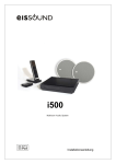
The i500 is a multi-room audio system for listeners to enjoy music throughout the entire home
by integrating the sound into the home’s fixtures. Thanks to its built-in ceiling speakers, the
i500 does away with the need for portable MP3 devices or individual sound systems in each
room. The Series is also equipped with intercom features for room-to-room communication,
electronic baby monitors, etc.
Some of the i500 Series features:
Enjoy music throughout the entire house
Access different music channels, including a disc player and an iPod docking station
with full control allowing the user to navigate throughout a full collection of music
Wireless Remote Control Unit
The i500 Series does not require hook-up from a dedicated computer. No technical computer
skills are required to fully enjoy all the features equipped to the system.
With the i500 Series it is possible to distribute different music channels to as many as 32
separate rooms from a Master Unit.
The Master Unit (ref. 51121) is equipped with the basic features:
FM tuner with built-in RDS and RF
75 ohm coaxial connectors for
antenna
CD/DVD disc players able to
“reproduce” audio CD, CD-MP3 and
DVD-MP3
connection to Universal Dock for
iPod (ref. 52222)
Two RCA inputs for external sound
devices with independent regulator
and level indicator
Data and sound (4 channels)
output line via RJ45 connector
Direct connection to the electrical
power source (110 to 240Vac/35W)
ref.51121
ref.52222
A Main Speaker (ref. 55101) and a Passive Speaker (ref. 55301) are installed in each zone or
room. Flush-mounted in the ceiling, they become integrated into the home without the need for
entertainment centers, counters or any other type of external fixture
A bus-type cable connection is required to communicate the Master Unit with all the Main
Speakers within the system. The wired connection provides optimal sound quality reception,
free of interference and interruptions, thus guaranteeing total privacy from possible intrusions
(involuntary or intentional) from outside the home.
The Main Active Speaker (ref. 55101) integrates the control and sound electronics of each zone
or room and is equipped with the following basic features:
L
Multiroom Audio System
FM tuner with built-in RDS and 75
ohm RF coaxial antenna connector
Wireless data and sound
communication with 52121 Remote
Control Unit
Data and sound (4 channels) input
line from the Master Unit: 8 wires
5+5W sound amplifier
Built-in two-way loudspeaker
8 ohm output for Passive Speaker
(ref. 55301)
Line output (4 wires) for Auxiliary
Active Speaker (ref. 55201)
Connection to the electrical power
source (110 to 240Vac/20W)
ref. 55101
The Auxiliary Active Speaker (ref. 55201) is ideal for zones or rooms where greater sound
power is required. Its features include:
5+5W sound amplifier
Built-in two-way loudspeaker
8 ohm output for Passive Speaker
(ref. 55301)
Line input (4 wires)
Connection to electrical power
source (110 to 240Vac/18W)
ref. 55201
The entire system is handled from Remote Control Units (ref. 52121). They do not require any
installation. The Remote Control Unit Base (ref. 52221) needs be connected to the mains,
acting as the remote’s platform as well as providing battery charge for the Remote Control Unit:
Graphic interface with 2.2” color TFT
Built-in microphone
3.5 mm input jack for external sound
source
Wireless data and sound communication
with Main Active Speaker (ref. 55101)
Battery charger connected to the
electrical supply (110 to 240Vac/5W)
ref. 52121 (Remote Control Unit)
ref. 52221 (Remote Control Base)
2QO\XVH%DVHWRFKDUJH5HPRWH&RQWURO8QLWPRGHOEDWWHULHV
LQVWDOODWLRQPDQXDO
3UHLQVWDOODWLRQ
SUHYLRXVUHFRPPHQGDWLRQV
The i500 Series requires basic pre-installation. To avoid future issues and ensure optimal
system operation, follow these prior recommendations.
3RZHU6RXUFH
Power source wires should be compliant to regulations in force.
It is recommended that the power source to Master Unit (ref. 51121),
Main Speakers (ref. 55101) and Auxiliary Active Speakers (ref. 55201)
be from the same automatic switch in order to facilitate isolation and
disconnection of the sound system independent from the rest of the
home’s electrical consumption. This will also avoid signal reception and
sound interference with other appliances such as extractor fans, air
conditioning, refrigerators, fans and the like (see wiring diagram in
Chapters 3.1, 4.1 and 4.2).
,03257$17GRQRWVXSSO\SRZHUWRWKHV\VWHPXQWLOLWLVFRUUHFWO\LQVWDOOHGDQG
FRQQHFWHG
&RPPXQLFDWLRQ/LQH
The communication line (ref. 57101) is an 8 wire connecting hose that connects Master Units
(ref. 51121) to all Main Speakers (55101)
2
To make connection 4 (yellow) use 1mm cross-section wires. For the remaining connections
2
use 0.25mm cross-Section wires. It may be necessary to increase the wire cross-Section in
systems with a large number of units and/or great distances. In this case consult with EIS
Technical Services.
Bus-type communication line distribution is necessary to keep the length of the shunts to each
Main Speaker (“stub”) to the minimum. This is especially important in systems greater than 100
meters and/or ten Main Speakers. In smaller systems star or mixed connections are possible.
/LQH5HLQIRUFHPHQWPRGXOH
It may be necessary to use a Line Reinforcement module (ref. 53002) in some cases. This
module would be pluged in the Main Active Speaker (ref. 55101)
The location of the device is very important:
In a bus-type system it should be installed in one or both ends of the system (see the
figure)
In star or mixed type systems look for the longest straight path between two points and
install the device on one or both ends of the system.
L
Multiroom Audio System
installation length
0..100m
100..200m
200..600m
# Main Active Spk. (55101)
# Line Reinf.Device (53002)
0..10
10..20
20..32
0
1
2
)07XQHUV
Installation of the 75 ohm FM antenna must be according to adequate techniques of installation
and signal distribution for antennas:
Ensure that the FM band amplifier is in the header of the antenna installation
The installation should include as many distributors as necessary to reach all antenna
feeds in the Master Unit and Main Speakers.
Because RDS information reception is more demanding in terms of signal/noise proportion than
a simple FM signal, in some areas where signal reception is not optimal it may not be possible
to receive RDS information. Also not all stations broadcast RDS information so the RDS
function may not always be available.
In areas of very strong FM signal reception the antenna may be replaced by a simple 76cm long
wire inserted into the nucleus of the ANT connector. In this event the wire should be placed as
far away as possible from sources of electromagnetic interference such as motors, contact
units, relays, fluorescents, halogens, and the like.
&RYHUDJHRI5HPRWH&RQWURO8QLW
The entire system is solely and uniquely operated by using the 51121 Remote Control Units
installed in each of the zones or rooms included in the system.
It is VERY IMPORTANT to carefully choose the location AND ORIENTATION of the Main
Speaker when planning the pre-installation.
7KH0DLQ$FWLYH6SHDNHUUHILVYLVXDOO\GLVWLQJXLVWDEOHIURPWKHUHVWRIWKH
6SHDNHUVE\WKHEOXH/('HPEHGGHGLQWKHIURQWJULOO
LQVWDOODWLRQPDQXDO
Place the Main Speaker in a preferential location in the room, as clear from any obstacles
as possible, especially metallic objects.
Position the Main Speaker in way that the LED is facing the Remote Control Unit.
P
P
P
P
The location of the remaining Speakers (Auxiliary Active Speakers 55201 and Passive
Speakers 55301) does not affect the coverage of the Remote Control Unit.
7RIDFLOLWDWHFRPPXQLFDWLRQEHWZHHQWKH&RQWURO8QLWDQGWKH0DLQ6SHDNHUIROORZDOO
WKHUHFRPPHQGDWLRQVLQFKDSWHU
L
Multiroom Audio System
,QVWDOOLQJWKH0DVWHU8QLW
&RQQHFWLRQWR&RPPXQLFDWLRQ/,1(
The Master Unit (ref. 51121) is connected to the communication line by means of a Line
Connector module (ref. 573x1). The cable supplied with the Master Unit must be specifically
used for this connection.
The Line Connector module is available in several colours and can be connected to leading
market switch brands by using the adapters listed in the EIS catalog (BJC, Jung, Legrand,
Niessen, Schneider, Simón, bTicino, ...).
Connection to the power supply is made with the cable supplied with Master Unit (see
installation recommendations in Chapter 2.1).
L N
230V
The Master Unit has a 75 ohm antenna input for FM tuner which is built-in (see Chapter 2.3).
$ 57 59 58 4
[
%'& (*)
54 53 52 51
# " !
%'& (*)
4
$ # " !
LQVWDOODWLRQPDQXDO
&RQQHFWLRQWR8QLYHUVDO'RFNIRUL3RG
To access music stored in an iPod, the Master Unit (ref. 51121) is equipped with a back panel
connection to the Universal Dock for iPod (ref. 52222). The connection is only available with
this unit and should not used for any other purpose.
/ 01 2
34
/6
/5
789
,-.-,
:;<=
0<
,-.-,
>
&RQQHFWLRQWR([WHUQDO6RXQG6RXUFHV
On its back panel, Master Unit (ref. 51121) is equipped with 2 RCA inputs to connect 2 external
sound sources as L1 and L2.
([WHUQDO/VRXQGLQSXWVKDUHVLJQDOZLWKL3RGZLWKWKLVRQHDVSULRULW\7KDWPHDQV
WKHPXVLFLQE\/LVRQO\DYDLODEOHZKHQL3RGLVQRWFRQQHFWZLWKWKHGRFN
The maximum allowable length for this connection depends on the external devices that supply
the signal (consult the manufacturer’s technical specifications). The length tends to vary
between 1 and 10m. The input signal level can be adjusted using a potentiometer together with
a LED.
B CD E
FG
BI
BH
?@A@?
JKL
MNOP
CO
?@A@?
Q
There are three alternatives for connecting an external sound source to the Master Unit:
(1) Preferably use the music system line out as an external sound source. This output
ensures a constant signal which is independent of the system’s volume control.
LINE OUT
L
R
+
L
Multiroom Audio System
(2) In systems equipped with a REC OUT (such as HI FI systems), connection to the
51121 Master Unit can be installed between the REC OUT and the music system’s
amplifier.
TAPE
L
R
OUT
IN
REC
L
R
IN
OUT
(3) The headphone output can be used in systems with no LINE OUT or REC OUT (such
as walkman, compact stereos, MP3 players …). This output is regulated by the
system’s volume output and must therefore be adjusted with the level potentiometer on
the 51121 Master Unit to achieve the ideal signal level.
RTS
LQVWDOODWLRQPDQXDO
,QVWDOOLQJ6SHDNHUVLQHDFK]RQH
,QFKRRVLQJWKHORFDWLRQRIWKH0DLQ6SHDNHULWLV9(5<,03257$17WRIROORZDOO
UHFRPPHQGDWLRQVLQGLFDWHGLQ&KDSWHU
%DVLFLQVWDOODWLRQ
L N
230V
Each Main Active Speaker (ref. 55101) requires simple installation as per the following diagram.
230V
L
N
Z*W`_
v fh h np
u o fdf q
g ht f
r o i q sf
g o npq
m c n h fe
g h ikjl
abdc e f
4
Z\[^]
4
UV WYX
([WHQGHGLQVWDOODWLRQ
In zones or rooms where more than two speakers are required it is possible to add as many
pairs of Auxiliary Active Speaker (ref. 55101) + Passive Speaker (ref. 55301) as desired to
cover the entire sound system area.
RR
L
4
N
L
230V
Multiroom Audio System
{
yz
}~
|
|
|
|
4
N
L
230V
~
{
yz
~
}~
|
|
|
4
N
L
230V
|
{
yz
~
~
|
|
|
|
y
~
|
4
L N
230V
wTx
LQVWDOODWLRQPDQXDO
,QVWDOODWLRQFRQILJXUDWLRQ
,QWKHIROORZLQJSURFHVVLWLVDVVXPHGWKDWDOOWKHXQLWVDUHQRWLQVWDOOHGDQGVWLOO
XQGHUIDFWRU\VHWWLQJV7RUHVHWWKHV\VWHPWRIDFWRU\GHIDXOWVHWWLQJVVHH&KDSWHU
,QVWDOOHDFK0DLQ6SHDNHUZLWKLWVRZQ5HPRWH&RQWURO8QLW
6XSSO\LQJSRZHUWRWKHV\VWHP
Engage the automatic switch that
feeds the power to all system
components.
Review that Master Unit and ALL Main Speakers emit a SLOW FLASHING signal to
indicate that they are NOT INSTALLED.
not installed
Wait 10 seconds minimum with the installation un-powered before supplying power to
the system
6XSSO\LQJSRZHUWRWKH5HPRWH&RQWURO8QLWV
Use a tool to open the battery compartments in the
Remote Control Units and insert the batteries being
careful to align the polarity correctly. Only use the
rechargeable batteries supplied with the product
(AAA NiMH 1,2V). Do not discard used batteries
mixed with household waste
Place the Remote Control Units in their respective Remote Control Bases and connect
them to any electrical outlet in the home (it is not necessary for these outlets to be
controlled by the automatic switch of the rest of the system elements of 51121 Master
Unit, 55101 Main Speakers and 55301 Auxiliary Active Speakers.)
The Remote Control Unit displays the initial screen, pending start up of the installation
process.
battery
wT L
Multiroom Audio System
The Remote Control Unit can be operated while stationed in the base. It is
recommended that the remote NOT BE SEPARATED FROM THE BASE until the
batteries are completely charged.
$VDJHQHUDOUXOH,7,65(&200(1'('WKDWZKHQQRWLQXVHWKH5HPRWH
&RQWURO8QLWEHLQVHUWHGLQLWV%DVH
/LQNHDFK5HPRWH&RQWURO8QLWZLWKLWVRZQ0DLQ6SHDNHU
The Remote Control Unit together with the Main Speakers use a single "home address"
which ensure that the system operates independently and free of any other i500
systems installed in neighboring homes. This address is automatically assigned with no
direct user intervention during the system configuration procedure
Push the key “install”
If the Remote Control Unit does not
find any Main Speaker, will appear on
the display "No home adress":
repeat the process following the
indicationses of chapter 8
(Recommendations to achieve
communication between the Remote
Control Unit and the Main Speaker)
install
,03257$17WKH5HPRWH&RQWURO8QLWZLOOFRPPXQLFDWHRQO\ZLWKWKH0DLQ
6SHDNHUVVRWKH5HPRWH&RQWURO8QLWPXVWEHLQVLGHRIWKH0DLQ6SHDNHU
FRYHUDJHVHHFKDSWHU
When the Remote Control Unit connect with the Main Speaker, it will take the "home
address" and will link with the speaker to program his name: the Main Speaker emit a
beep audio signal and at the moment the speaker emit a FAST FLASHING with light
signal.
Home
Est
rellaaddress
de mar
¢Y£ ¤
¢Y£ ¤
¢Y£ ¤
Amaral
Zone name:
Escapar
KI TC EN
Est rella de mar
¥
edit
w^¡
LQVWDOODWLRQPDQXDO
At this point a name is given to the Main Speaker which is emitting the BEEP signal.
Use the navigation keys.
The zone name is linked with the Main Speaker and NOT with the Remote Control Unit.
Because the Speaker is built-in to the ceiling and permanently fastened it is
recommended that the name be indicative of the zone or room, for example
“KITCHEN”, “BEDROOM”, “OFFICE”, “ATTIC”, “PANTRY”, and the like.
Once the process of linking and programming the name of the Main Speaker has been
completed, the indicative LED will stop flashing and turn off. At that time the Speaker
and Remote Control Unit are completely operational. The LED will become lit when the
background music is activated and will turn off when the background music is turned off.
The zone name with which it is linked will appear on the Remote Control Unit.
., 7&+(1
²
linked with the
zone "KITCHEN"
§k¨ ©kª«¬
®k®¯ °±
Monday, 04/ 06/ 08
When had been installed the first Remote Control Unit with the first Main Speaker, leds
of the Master Unit stop flashing and the sound sources that are available at the time
stay illuminated.
L2 external sound source connected
L1 external sound source connected
Universal iPod Dock connected
Disk inserted
FM tuner active
This step must be repeated with all the Remote Control Unit and Main Speaker sets
installed in the different zones or rooms in the home.
,03257$17$//WKH5HPRWH&RQWURO8QLWVDQG$//WKH0DLQ
6SHDNHUVPXVWEHOLQNHGLQWKHVDPHZD\EHIRUHWKHLQVWDOODWLRQSURFHVVFDQ
EHFRPSOHWHG
At this point the Master Unit, all the Main Speakers and all The Remote Control UNits
share the same "home address", avoiding interference from any other nearby systems.
wT¦
L
Multiroom Audio System
,QVWDOOVHYHUDO0DLQ6SHDNHUVZLWKWKHVDPH5HPRWH&RQWURO8QLW
The i500 multi-room system allows for a single Remote Control Unit to operate different Main
Speakers. However, in order to make the best use of its features, it is HIGHLY
RECOMMENDABLE that each zone or room have a Main Speaker and a Remote Control Unit.
$5HPRWH&RQWURO8QLWLVRQO\OLQNHG:,7+$6,1*/(0DLQ6SHDNHUDWDWLPH
linked
For use the same Remote Control to install
several Speakers, first must be cleared actual
link pressing the key "link"
.
´kµ ¶k·¸¹º
»k»¼ ½¾
Monday, 04/ 06/ 08
link (clear)
The start-up screen appears indicating that the Remote Control Unit is not linked. When the
“link” key
is pressed again the Remote Control Unit searches an uninstalled Main
Speaker, which then signals the event with a RAPID FLASHING and a BEEP sound signal.
The remaining process is as described in the previous point.
not linked
link (new)
Am aral
Zone nam e:
Escapar
LI VI NG R OM
Est rella de m ar
edit
wT³
LQVWDOODWLRQPDQXDO
/, 9, 1*
É
linked with
zone "LIVING"
É
À Á ÂÁ ÃÄ
ÅÅ Æ ÇÈ
Monday, 04/ 06/ 08
,QFRUSRUDWHDQHZ5HPRWH&RQWURO8QLWWRWKHFXUUHQWV\VWHP
When all the Main Speakers are installed and a new Remote Control Unit wil be added, the
following procedure:
2SHQWKHLQVWDOODWLRQ
Briefly
push
(under 2
seconds)
the “reset”
button
Ê
Short press: OPEN installation
The Master Unit leds emit FAST FLASHING to indicate that the installation is opened to
receive new Remote Control Units. Every QRW OLQNHG Main Speakers emit FAST
FLASHING also.
open
installation
,QVWDOOWKHQHZ5HPRWH&RQWURO8QLW
Come close to any not linked 0DLQ6SHDNHUVIODVKLQJDQGSUHVVWKHLQVWDOONH\
. When the Remote Control Unit finds the home address, it will change the key
"install"
by "link"
.
not linked
Hom
e address
Est
rella
de m ar
install
link
wT¿
L
Multiroom Audio System
&ORVHWKHLQVWDOODWLRQ
Briefly
push
(under 2
seconds)
the “reset”
button
Ê
Short press: CLOSE installation
All the leds (Master Unit and Main Speakers) stop flashing to indicate that the
installation is CLOSED, meaning that it will not admit new Remote Control Units
closed
installation
/LQN5HPRWH&RQWUROZLWKLWV0DLQ6SHDNHU
Follow the steps indicated in chapter 2 of User Manual
2WKHUFRQILJXUDWLRQRSWLRQV
Other configuration options are available on the settings menu of the Remote Control Unit. To
Access the unit, once the Speaker control unit has been linked, press the “Menu” key, select the
“Settings” option and enter “Installation”.
linked with
"KITCHEN" zone
ØÙÚ Ú Û ÜÝÞ
ØÙÚ Ú Û ÜÝÞ
ÍkÎ ÏkÐkÑÒÓ
Alar m 2
ÔÔÕ Ö ×
Aut o St andby
Light
Monday, 04/ 06/ 08
Language
Them es
IEst
nstrella
allat ión
de m ar
menu
Select
Settings
Select
Installation
enter
enter
=RQH1DPH: change the actual name of the zone
0\ JURXSV define 8 groups of zones for
intercom calls to several areas simultaneously, for
example, “GROUP 1” can include the zones
“KITCHEN”, “LIVING ROOM” and “GARAGE”.
3HUPLVVLRQV: block the access to certain
operations such as limiting the use of intercom
calls.
1HLJKERU =RQHV Designed for 55101
Main Speakers that are installed in the
same zone or room and, thus, with the
ability chain by issuing group calls
between them.
0RQR 2XWSXW Option for when a room
has a single 55101 Main Speaker,
without a 55301 Passive Speaker.
ËTÌ
LQVWDOODWLRQPDQXDO
,03257$17WKHSURJUDPPLQJRIWKHDGMXVWPHQWFRUUHVSRQGV:,7+7+(=21(RU
5220ZKHUHWKH0DLQ6SHDNHULVLQVWDOOHG127:,7+7+(5(027(&21752/
81,77KHUHIRUHLIWKH&RQWURO8QLWLVODWHUOLQNHGZLWKDQRWKHU0DLQ6SHDNHUWKH
VHWWLQJVZLOOFKDQJHDQGEHFRPHWKRVHRIWKHQHZ0DLQ6SHDNHU
àá â â ã äåæ
5HVHWWKHV\VWHPZLWKIDFWRU\GHIDXOWVHWWLQJV
In order to operate, the Master Unit, Main Speakers and Remote Control Units need to have a
"home address" assigned. The "home address" is a 16 bit number that all elements of a single
installation share. This identifier ensures that no interferences from neighboring i500 systems
will be experienced. The identifier is empty from the factory and is automatically calculated in
the installation process (see Chapter 5).
To reboot the system, delete all the identifiers and reset the units to the factory settings,
following this procedure:
Keep the “reset” button pressed on the Master Unit for 10 seconds until all the frontal LEDS
are illuminated.
ç
(10sg) factory setting
Next, all the LEDS on the Master Unit and all the Main Speakers signal SLOW
FLASHING to indicate they are NOT INSTALLED
not installed
ËTß
L
Multiroom Audio System
For each of the Remote Control Units, press the “link” key to delete the association.
linked
êkë ìkíîïð
ñkñò óô
not linked
Monday, 04/ 06/ 08
link (clear)
At the start-up screen, press the “on/off” key
navigation for 5 seconds.
, “intercom calls”
, and left
start-up
screen
not-installed
reset
5sg
To install all the units in the house with the same identifier, follow the procedure described in
Chapter 5.
èé
LQVWDOODWLRQPDQXDO
7HFKQLFDO&KDUDFWHULVWLFV
0DVWHU8QLW
öø÷^÷'ùø÷
Measurements
Voltage
Consumption demand
Input signal
Input impedance
Output signal
Passband
Frequency range
Antenna impedance
Antenna sensitivity
Tuner distortion
Number of station pre-sets
Lenght to line conector 573x1
Number of zones in system
System length
úüû ý
85
ýÿþ ÿú
ú
274x54x250
230
mm
Vac
W
mVeff
Kohms
Veff
Hz
MHz
ohms
uV
%
264
35
3800
10
150
2
2,8
20
87,5
15000
108
75
1,7
0,1
3,5
0,5
30
2
32 (**)
600 (**)
10
100
width x height x depth
50/60Hz
RCA inputs L1 , L2
RCA inputs L1 , L2
terminals 51,52,53,54
m
(**) consult
(**) consult
m
5HPRWH&RQWURO8QLW%DVH
!
#"
Measurements
Voltage ref.52221
Consumption demand ref.52221
Input signal
Input impedance
Passband
Wireless transceiver
Range
85
50,5x183x20
78,5x116x133,5
78,5x213x133,5
230
20000
Measurements
Voltage
Consumption demand
Input signal
Input impedance
Output signal
Output impedance
Aux.amplifier switch on signal
Output external speaker (8 ohm)
Inside speaker (8 ohms)
85
/10321-345
220x93
190x85
220x8,5
230
5
264
20
12
5
5
1"
5"
75
20
0,05
87,5
75
1,7
0,1
2,4
10
100
ref.52121 (width x height x depth)
ref.52221 (width x height x depth)
set (width x height x depth)
50/60Hz
discman input
discman input
discman input
-3476
2,8
36
2,8
47
tweeter
woofer
Left/right channel separation
Passband
Distortion
Frequency range
Antenna impedance
Antenna sensitivity
Tuner distortion
Number of station pre-sets
Wireless transceiver
Number of zones in system
System length
264
5
2,4
5
0DLQ$FWLYH6SHDNHU
()(*,+*
-. /
$%#&'
mm
mm
mm
Vac
W
Veff
Kohms
Hz
GHz
m
1
10
20
ý þ ú ú
20000
0,1
108
3,5
0,5
30
8#03--97/7:;
mm
mm
mm
Vac
W
Veff
Kohms
Veff
ohms
V
W
W
exterior (diameter x depth)
cavity (diameter x depth)
front grill (diameter x height)
50/60Hz
terminals 51,52,53,54,57
terminals 51,52,53,54,57
terminals 65,66
terminals 65,66
terminal 62
dB
Hz
%
MHz
ohms
uV
%
GHz
32 (**)
600 (**)
m
(**) consult
(**) consult
èõË
L
Multiroom Audio System
$X[LOLDU\$FWLYH6SHDNHU
<)<>=>?@
AB C
C1D3E1A3FG
Measurements
Voltage
Consumption demand
Input signal
Input impedance
Aux.amplifier switch on signal
Output speaker signal (8 ohm)
Inside speaker signal (8 ohms)
85
5
3DVVLYH6SHDNHU
M)M>N>OP
QR S
Measurements
Tweeter
Woofer
Impedance
Power
èè
12
5
5
20000
0,1
dB
Hz
%
264
18
1"
5"
75
20
0,05
S1T3U1Q3VW
I#D3AAJ7C7KL
mm
mm
mm
Vac
W
Veff
Kohms
V
W
W
2,8
50
tweeter
woofer
Left/right channel separation
Passband
Distortion
220x93
190x85
220x8,5
230
A3F7H
Q3V7X
220x72
190x64
220x8,5
1"
5"
8
terminals 65,66
terminals 65,66
terminal 62
Y#T3QQZ7S7[\
mm
mm
mm
5
exterior (diameter x depth)
cavity (diameter x depth)
front grill (diameter x height)
50/60Hz
exterior (diameter x depth)
cavity (diameter x depth)
front grill (diameter x height)
ohms
W
LQVWDOODWLRQPDQXDO
4XLFN5HIHUHQFH*XLGHIRU5HPRWH&RQWURO8QLW2SHUDWLRQ
Linked zone
Music ON
^`_ a b`c,d e
b`d efahg i,jkf_ lh^
I n t he air t onight
Battery
Menu
Information window
Return to previous screen
Link
Menu input
Multifunction keys
Install
Microphone
Information
Navegation keys
Memory store
OK key
Memory clear
Quick scroll through list
Intercom
Volume
Music channel
Music ON/OFF
Cancel/snooze alarm
Timer
Close floating screen
Est rella de mar
97.9
SER
Base connector
Local audio channel input
Operate and control Central Unit FM tuner
Navigate through the Central Unit audio CD/DVD player
m n`o p`q r sft
Menu
Navigate through iPod connected to Central Unit
Manage and program Main Speaker FM tuner
Intercom operations
Setting audio levels
Store and activate "ideal" function
Settings
General standby
Do not disturb: no individual calls are received
Electronic baby monitor activated
Free-hands auto-response
Alarms
Timer
7]
è
L
Multiroom Audio System
5HFRPPHQGDWLRQVWRDFKLHYHHQKDQFHGFRPPXQLFDWLRQEHWZHHQWKH
5HPRWH&RQWURO8QLWDQGWKH0DLQ6SHDNHU
Operate the Remote Control Unit in a vertical position
5m.
vw
xv
Do not move while operating the Remote Control Unit.
5m.
yz
{y
Main Speaker coverage is better on the LED side: preferably aim the Remote Control Unit
towards that zone and avoid operating from the sides.
5m.
u
è
LQVWDOODWLRQPDQXDO
P
P
P
P
Avoid nearby devices that emit Bluetooth, Wi-Fi or any other radiofrequency that transmits
at 2.4 GHz.
,03257$17:KHQWKH5HPRWH&RQWURO8QLWORVHVFRPPXQLFDWLRQZLWKLWVOLQNHG
6SHDNHUWKH V\PEROGLVDSSHDUVDORQJZLWKWKHQDPHRIWKH]RQH,QWKLVFDVH
WKH5HPRWH&RQWURO8QLWZLOODWWHPSWWRUHHVWDEOLVKWKHOLQNXQWLOLWLVHVWDEOLVKHG7R
IDFLOLWDWHWKLVRSHUDWLRQIROORZWKHDERYHUHFRPPHQGDWLRQVXQWLOWKH V\PERO
VWRSVIODVKLQJ
,IWKHOLQNFDQQRWEHHVWDEOLVKHGSUHVVWKH³OLQN´NH\
WREUHDNWKHOLQNDQG
SURFHHGWRUHWU\ZLWKWKLVRUDQRWKHU6SHDNHUE\IROORZLQJWKHSURFHGXUHLQ&KDSWHU
RI8VHU0DQXDO
7|
è
(OHFWUyQLFD,QWHJUDOGH6RQLGR6$
HEADQUARTERS
Polígono Malpica Calle F Oeste
Grupo de Naves Gregorio Quejido, 87-88
50016 Zaragoza (España)
Tel.: 34 976 465 550
Fax: 34 976 465 559
[email protected]
MADRID
Poeta Rafael Morales 2, oficina 2ºB
28703 San Sebastián de los Reyes
Madrid (España)
Tel.: 34 91 6593 678
Fax: 34 91 6239 525
[email protected]
www.eissa.com
}~1!
> h
f `
,
CC-1130-01
64460042
ESTE CAJETÍN NO FORMA PARTE DEL MANUAL
TOLERANCIADE MEDIDA LIBRE
SISTEMA DE TOLERANCIAS ISO 8015
TOLERANCIAS GENERALES ISO 2768-mK
TOLERANCIAS CRITICASISO 2768-fH
89 ::0;: < =: 9:;):>)?? @A :9 < >B :
C = @ED F G H)8 I >J <);):>? <)A? @ A : 9 <>B C >KML 9C >B C L A :
C =N O P D Q RS6K :>: 9 <)A? @ A : 9 <>B : =
C =@EN O P D Q T UB 9C ? C B <)A? @ A :9 <>B : =
LAS COTAS
ENCUADRADAS
SON CRITICAS
& ')(!*+ ,( -.)+ /0-.
+ -1 / 20( .
3 4(654)+ & + 5 37
Modificación
V W Denominación
MANUAL INSTALACION S500
inglés
Material
Fecha
! Nombre
^!_ `a
Proyectado
[ \ V
01/12/2008
L.ABOS
Página
_b a
Dibujado
! ] 19/02/2009
L.ABOS
1 de 1
Aprobado
X)YY Z V
19/02/2009
L.ABOS
tinta: blanco y negro
portada y contraportada papel estucado brillo 135gr
resto de hojas 80gr
Escala
1:1
Din A4
Código
c %"Pieza
#
64460042
Código
Plano
!"#
CC-1130
Edición
$" % 01


