1
L05U_AA_312278515051.book Page 7 Friday, March 4, 2005 10:42 AM
Mechanical Instructions
L05U AA
4.
EN 7
4. Mechanical Instructions
Index of this chapter:
4.1 Set Disassembly
4.2 Service Position
4.3 Assy/Panel Removal
4.4 Set Re-assembly
Note: Figures below can deviate slightly from the actual
situation, due to different set executions.
4.1
Set Disassembly
2
Warning: Be sure to disconnect the AC power from the set
before opening it.
4.1.1
Rear Cover
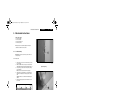
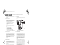
1. Remove all screws. If you do not remove them, you cannot
access the clips.
2. Tilt the set a little forward, so that you can release the two
clickfit clamps that are located at the bottomplate of the set.
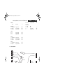
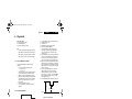
3. Four openings (1) can be found at the top. The openings
are very small (2).
Note: Some sets only have the two inner openings.
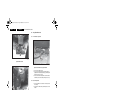
4. Underneath every opening there is a clip. Push this clip
down with a very thin piece of metal (3), until you hear a
click.
Caution: do not use a screwdriver, this will damage the
cabinet.
5. When all four clips are pushed down, the back cover can
be removed.
E_13950_012 .eps
050404
Figure 4-2 Opening
3
1
E_13950_013.eps
050404
Figure 4-3 Pushing clips down
4.2
E_13950_011 .eps
050404
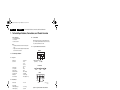
Figure 4-1 Rear cover (for FL13 styling)
Service Position
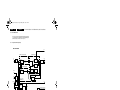
Before placing the Mono Carrier in its service position, remove
the Front Interface assy/panel (see paragraph “Front Interface
Assy/Panel”) and the Side AV assy/panel (see paragraph “Side
AV Assy/Panel”).