1
EN 10
5.
L05L AA
Service Modes, Error Codes, and Fault Finding
5. Service Modes, Error Codes, and Fault Finding
•
Index of this chapter:
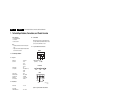
5.1 Test Points
5.2 Service Modes
5.3 Problems and Solving Tips Related to CSM
5.4 ComPair
5.5 Error Codes
5.6 The Blinking LED Procedure
5.7 Protections
5.8 Fault Finding and Repair Tips
5.1
Test Points
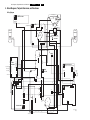
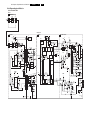
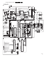
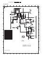
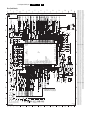
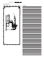
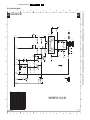
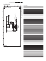
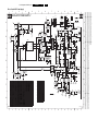
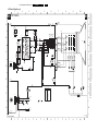
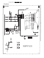
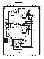
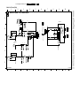
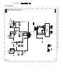
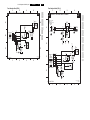
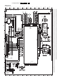
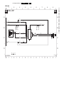
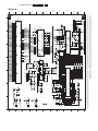
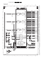
This chassis is equipped with test points in the service printing.
In the schematics test points are identified with a rectangle box
around Fxxx or Ixxx. These test points are specifically
mentioned in the “Test Point Overview” as “half moons” with a
dot in the center.
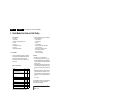
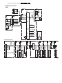
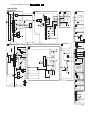
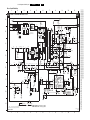
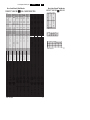
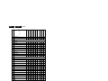
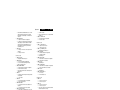
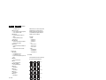
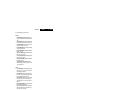
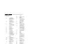
Table 5-1 Test point overview
Test point
Circuit
Diagr.
F508, F535, F536, F537, F552, F561, F563, F573, F664, Power supply
I513, I518, I519, I524, I531, I533, I546
A1
F401, F412, F413, F414, F418, F452, F453, F455, F456, Line & Frame
F458, F459, F460, F461, I408, I416, I417, I420, I462,
Deflection
I468
A2
F003, F004, I001, I002
Tuner IF
A3
F201, F203, F205, F206
UOCIII
A4
F240, F241, F242
Features &
Connectivities
A5
F952, F955, I951, I952
Audio Amplifier A7
F692
Front Control
A9
F331, F332, F333, F338, F339, F341, F351, F353, F354 CRT Panel
B1
F361, F362, F381, F382
B2
ECO Scavem
Perform measurements under the following conditions:
• Television set in Service Default Alignment Mode.
• Video input: Color bar signal.
• Audio input: 3 kHz left channel, 1 kHz right channel.
5.2
All service-unfriendly modes (if present) are disabled. The
service unfriendly modes are:
– Timer / Sleep timer.
– Child / parental lock.
– Blue mute.
– Hotel / hospital mode.
– Auto shut off (when no “IDENT” video signal is
received for 15 minutes).
– Skipping of non-favorite presets / channels.
– Auto-storage of personal presets.
– Auto user menu time-out.
– Auto Volume Leveling (AVL).
How to Enter
To enter SDM, use one of the following methods:
• Press the following key sequence on the remote control
transmitter: “062596” directly followed by the MENU button
(do not allow the display to time out between entries while
keying the sequence).
• Short the jumper wire 9252 with a cold ground on the family
board (for example the tuner casing) and apply AC power.
Then press the power button (remove the short after startup).
Caution: Entering SDM by shorting wire 9252 with ground
will override the +8V-protection. Do this only for a short
period. When doing this, the service-technician must know
exactly what he is doing, as it could damage the television
set.
• Or via ComPair.
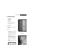
After entering SDM, the following screen is visible, with SDM in
the upper right corner of the screen to indicate that the
television is in Service Default Mode.
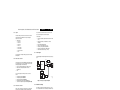
00028 L05US1 1.1 PUS1 0.7 SDM
ERR 0 0 0 0 0
OP 000 057 140 032 120 128 000
Service Modes
Service Default mode (SDM) and Service Alignment Mode
(SAM) offers several features for the service technician, while
the Customer Service Mode (CSM) is used for communication
between the call center and the customer.
This chassis also offers the option of using ComPair, a
hardware interface between a computer and the TV chassis. It
offers the abilities of structured troubleshooting, error code
reading, and software version readout for all chassis.
Minimum requirements for ComPair: a Pentium processor, a
Windows OS, and a CD-ROM drive (see also paragraph
"ComPair").
F_15050_013.eps
110205
Figure 5-1 SDM menu
5.2.1
Service Default Mode (SDM)
Purpose
• To create a predefined setting for measurements to be
made.
• To override software protections.
• To start the blinking LED procedure.
Specifications
• Tuning frequency: 61.25 MHz (channel 3).
• Color system: PAL M.
• All picture settings at 50% (brightness, color contrast, hue).
• Bass, treble and balance at 50 %; volume at 25 %.