1
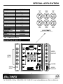
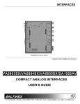
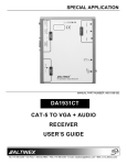
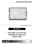
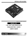
SPECIAL APPLICATION
MANUAL PART NUMBER: 400-0430-001
DA203-101
1-IN 1-OUT LINE DRIVER WITH
EQUALIZATION + AUDIO
USER’S GUIDE
SPECIAL APPLICATION
TABLE OF CONTENTS
Page
PRECAUTIONS / SAFETY WARNINGS ............... 2
GENERAL..........................................................2
GUIDELINES FOR RACK-MOUNTING ..............2
INSTALLATION .................................................2
CLEANING.........................................................2
FCC / CE NOTICE..............................................2
ABOUT YOUR DA203-101....................................... 3
TECHNICAL SPECIFICATIONS ............................ 3
DESCRIPTION OF DA203-101 ............................... 4
APPLICATION DIAGRAMS...................................... 5
DIAGRAM 1: TYPICAL SETUP ..........................5
DIAGRAM 2: INTERNAL VIEW ..........................6
INSTALLING YOUR DA203-101 ............................. 7
OPERATION............................................................... 7
ADJUSTMENTS.................................................7
TROUBLESHOOTING GUIDE ................................ 8
NO DISPLAY......................................................8
NO SOUND........................................................8
ALTINEX POLICY ...................................................... 8
LIMITED WARRANTY/RETURN POLICY ..........8
CONTACT INFORMATION ................................8
400-0430-001
1
SPECIAL APPLICATION
PRECAUTIONS / SAFETY WARNINGS
•
1
Please read this manual carefully before using your
DA203-101 Line Driver. Keep this manual handy
for future reference. These safety instructions are
to ensure the long life of your DA203-101 and to
prevent fire and shock hazard. Please read them
carefully and heed all warnings.
•
If the DA203-101 is not used for an extended
period, disconnect the power cord from the
power outlet.
1.4 CLEANING
•
Unplug the DA203-101 power cord before
cleaning. Clean surfaces with a dry cloth.
Never use strong detergents or solvents, such
as alcohol or thinner. Do not use a wet cloth or
water to clean the unit.
1.5 FCC / CE NOTICE
1.1 GENERAL
•
Unauthorized personnel shall not open the unit
since high-voltage components are inside.
•
Qualified ALTINEX service personnel, or its
authorized representative must perform all
service.
1.2 GUIDELINES FOR RACK-MOUNTING
•
This device complies with Part 15 of the FCC
Rules. Operation is subject to the following two
conditions: (1) This device may not cause
harmful interference, and (2) this device must
accept any interference received, including
interference that may cause undesired
operation.
•
This equipment has been tested and found to
comply with the limits for a Class A digital
device, pursuant to Part 15 of the FCC Rules.
These limits are designed to provide
reasonable
protection
against
harmful
interference when the equipment is operated
in a commercial environment. This equipment
generates, uses, and can radiate radio
frequency energy and, if not installed and used
in accordance with the instruction manual, may
cause
harmful
interference
to
radio
communications. Operation of this equipment
in a residential area is likely to cause harmful
interference in which case the user will be
required to correct the interference at their
expense.
Any changes or modifications to the unit not
expressly approved by ALTINEX, Inc. could
void the user’s authority to operate the
equipment.
•
•
Maximum operating temperature is 35°C.
Distribute the units evenly. Otherwise,
hazardous conditions may be created by an
uneven weight distribution.
• Connect the unit to a properly rated supply
circuit.
• Reliable
grounding
of
rack-mounted
equipment should be maintained.
1.3 INSTALLATION
•
For best results, place the DA203-101 on a
flat, level surface in a dry area away from dust
and moisture.
•
To prevent fire or shock, do not expose this
unit to rain or moisture. Do not place the
DA203-101 in direct sunlight, near heaters or
heat-radiating appliances, or near any liquid.
Exposure to direct sunlight, smoke, or steam
can harm internal components.
•
Handle the DA203-101 carefully as dropping
or jarring can damage internal components.
Do not place heavy objects on top of the
DA203-101.
•
•
•
To turn off the main power, be sure to remove
the cord from the power outlet. The outlet
should be installed as near to the equipment
as possible, and should be easily accessible.
400-0430-001
Do not pull the power cord or any cable that is
attached to the DA203-101.
2
SPECIAL APPLICATION
ABOUT YOUR DA203-101
Ultimately, the DA203-101 acts as a sync
processor, allowing you to combine horizontal and
vertical sync into composite sync or split a
composite sync into separate horizontal and
vertical syncs. Moreover, the DA203-101
incorporates the ability to control the sync detection
threshold allowing for even greater flexibility.
2
DA203-101
1-In 1-Out Line Driver with Equalization +
Audio
The DA203-101 is a multi-purpose RGBHV Line
Driver, Ground Loop Isolator, and Sync Processor.
As a Line Driver, the DA203-101 offers a single
output (5-BNC connectors for RGBHV). It will also
accept RGBS, RGsB, Component Video (Y, R-Y,
B-Y), S-Video, and Composite Video signals using
the appropriate channels. The DA203-101 does
not covert one signal format to another. If a
Component Video signal is the input, a Component
Video signal is the output. In the case of RGBHV
and RGBS input signals, the available outputs are
RGBHV or RGBS.
TECHNICAL SPECIFICATIONS
FEATURES/
DESCRIPTION
GENERAL
Inputs
Video Connectors
Audio Connector
Power Connector
Outputs
Video Connectors
Audio Connectors
Compatibility
Used to compensate for loss over long runs of
coaxial cable, the DA203-101 may be installed
alone, with an interface, or with additional
DA203-101
units
depending
on
system
requirements. Typically, the DA203-101 might be
used at the end of a cable run with an interface at
the head-end of the run.
Signal types
Resolutions - PC
Resolutions - HDTV
Television Standards
The DA203-101 is engineered for custom signal
alignment, enabling it to be modified to handle
cable runs of 300 feet or more. The DA203-101 is
compact and streamlined, making it easy to fit
virtually anywhere in a system.
In an audiovisual system, when different pieces of
equipment operating from different power sources
are connected, a ground loop can potentially occur,
usually causing a hum bar to roll from top to bottom
over a display image. Severe ground loops can
cause damage to equipment. The DA203-101 is
designed for installation between these pieces of
equipment to eliminate a ground loop problem. The
common mode range of the DA203-101 is +/-2V
with a video signal of 1V p-p. The DA203-101 may
also be used as a ground loop isolator for up to
three different composite video signals, using red,
green, and blue channels.
400-0430-001
DA203-101
BNC Female (5)
3.5mm Stereo Jack (1)
DC Power Jack (1)
BNC Female (5)
5-Pin Terminal Block (1)
RGBHV, RGBS, RGsB,
YPbPr, S-Video & C-Video
VGA through UXGA
480p,576p,720p,1080i
NTSC, PAL, SECAM
Table 1. DA203-101 General
MECHANICAL
Material
Finish
Height
Width
Depth
Weight
Panel Material
Panel Finish
T° Operating
T° Maximum
Humidity
MTBF (calc.)
DA203-101
0.091” Al
ALTINEX Black
1.0in (25mm)
5.2in (132mm)
4.3in (109mm)
1.0 lb (0.45 kg)
0.047” Al
Black Anodized
10°C-50°C
75°C
90% non-condensing
38,000 hrs
Table 2. DA203-101 Mechanical
3
3
SPECIAL APPLICATION
ELECTRICAL
DA203-101
Input Video
Analog Level
1.5Vp-p max.
Analog Impedance
75 Ohms
Sync Level
TTL
Sync Impedance
4.7k Ohms
Input Audio
Unbalanced Level In
0dBu
Impedance
10k Ohms
Output Video
Analog Level
0dB Gain
Analog Impedance
75 Ohms
Sync Level
TTL
Sync Impedance
75 Ohms
Output Audio
Unbalanced Level
0dB Gain
Impedance
50 Ohms
Power
External 9V, 1.1A
800mA max.
Power
7.2W
Table 3. DA203-101 Electrical
DESCRIPTION OF DA203-101
SYNC
TH
VIDEO
GAIN
MAIN
EQ
50
50
50
0
100
0
50
0
100
0
50
100
RED
GAIN
0
100
50
100
GREEN
GAIN
0
100
BLUE
GAIN
ADJUSTMENTS
(Default positions are shown.)
4
VIDEO
OUTPUT
VIDEO
INPUT
POWER
AUDIO
INPUT
400-0430-001
AUDIO
OUTPUT
4
SPECIAL APPLICATION
APPLICATION DIAGRAMS
5
DIAGRAM 1: TYPICAL SETUP
DA203-101
DA1907
400-0430-001
5
SPECIAL APPLICATION
DIAGRAM 2: INTERNAL VIEW
S/W
TH
H/W
TH
SIGNAL
DETECT
POWER
H/W
EQ
H/W
H/W
EQ
EQ
BNC FEMALE
HOR
H/C
SYNC
PROCESSING
V
VER
5 BNC
VIDEO
INPUT
GLI
GREEN
G
BLUE
B
RED
R
VIDEO
OUTPUT
H/W
H/W
EQ
GAIN
S/W
S/W
EQ
GAIN
TERMINAL BLOCK
LEFT
LEFT
RIGHT
RIGHT
AUDIO
STEREO
3.5mm
RS232
3.5mm
RX
POWER
2.5mm
9V, 1A
400-0430-001
RS-232 TO
TTL
MP
PS
6
MAIN
AUDIO
STEREO
BALANCED
SPECIAL APPLICATION
INSTALLING YOUR DA203-101
6
OPERATION
7
Step 1. Make sure that the correct power adapter
is connected to the unit. The DA203-101
uses a 9V 1.1A power supply.
The DA203-101 will operate successfully as long
as cables are attached properly and other technical
specifications are followed.
Step 2. Connect the cables from the video source
(computer) to the appropriate input
channels.
The adjustments on the DA203-101 Line Driver are
available to fine-tune the output image and to help
compensate for errors in picture quality, cable
quality, cable length and variations in equipment.
Step 3. Connect the audio source to the audio
input on the DA203-101 using a standard
3.5mm plug.
7.1 ADJUSTMENTS
SYNC TH
Step 4. Connect the output channels to the
display device (monitor, projector, etc…).
The SYNC THRESHOLD adjustment allows
changes to be made in the timing of the sync
pulses. Use caution when adjusting this
potentiometer since some monitors may lose
sync after only minor adjustments. Always start
this adjustment with the potentiometer set to the
50 position and make adjustment in small
increments.
MAIN EQ
Step 5. Connect the balanced audio output to the
input of the speakers, amplifier or other
audio device.
Step 6. Check the image quality on the display.
If the DA203-101 is working to eliminate a
specific ground loop problem, make sure
that all visible interference has been
eliminated. If the problem persists, the
ground loop may involve more than just
the two pieces of equipment, which are
interconnected.
The MAIN EQUALIZATION adjustment allows
compensation for very long cable runs or cables
that have higher than expected loss over the
length of the cable. Set this potentiometer to
zero for short cable runs and as a starting point
for adjusting for long cable runs.
VIDEO GAIN
If the DA203-101 is used for general
preventative measures, your image
should remain stable and interference
free. Due to potential changes in any
power/ground system, the DA203-101
works to eliminate potential ground loop
interference problems.
The VIDEO GAIN adjustment allows the output
levels on the red, green and blue outputs to be
adjusted above and below their input level. This
adjustment affects all three outputs equally.
Unity gain is achieved by setting all four of the
gain potentiometers to the 50 position.
RED, GREEN and BLUE GAIN
Step 7. Adjust the available settings for the best
image quality. The default settings are:
SYNC TH
= 50
VIDEO GAIN = 50
MAIN EQ
= 0
RED GAIN
= 50
GREEN GAIN = 50
BLUE GAIN = 50
The RED, GREEN and BLUE GAIN adjustments
allow the output level on any of the red, green or
blue outputs to be adjusted above and below its
input level. Each adjustment affects only one
output level. Unity gain on an individual output
is achieved by setting its potentiometer, as well
as the VIDEO GAIN potentiometer, to the 50
position.
NOTE: Some monitors are very sensitive
to the sync settings. Start this
adjustment from the 50 position
and adjust the potentiometer
slowly allowing the monitor to
respond to the changes in sync
pulses.
400-0430-001
7
SPECIAL APPLICATION
TROUBLESHOOTING GUIDE
8.2 NO SOUND
8
Cause 1:
Solution:
The source has a problem.
Check the source and make sure
that it is working at an appropriate
volume level and all source
connections are correct. If the
source is working and there is still
no sound, see Cause 2.
Cause 2: Cable connections are incorrect.
Solution: Make sure that cables are
connected properly. Also, make sure
that the continuity and wiring are
good. If there is still no sound
present, see Cause 3.
Cause 3: Destination amplifier has a
problem.
Solution 1: Make sure that the destination
amplifier is powered. If there is still
no sound, see Solution 2
Solution 2: Set the volume of the destination
amplifier to a reasonable level. If
there is still no sound, call ALTINEX
at (714) 990-2300.
We have carefully tested and have found no
problems in the supplied DA203-101. However, we
would like to offer suggestions for the following:
8.1 NO DISPLAY
Cause 1:
Solution:
Cause 2:
Solution:
Cause 3:
Solution:
Cause 4:
Solution:
Cause 5:
Solution:
The source has a problem.
Check the source and make sure
that there is a signal present and all
source connections are correct. If
the source is working and there is
still no display, see Cause 2.
The path has a problem.
Connect the source directly to the
display device, bypassing the
DA203-101. If the image is good,
see Cause 3.
Cable connections are incorrect.
Make sure that cables are properly
connected. Also, make sure that the
continuity and wiring are good. If
there is still no display present, see
Cause 4.
An adjustment is out of tolerance.
Make sure the SYNC TH is set to 50
and that the MAIN EQ is set to zero.
Slowly adjust the SYNC TH up and
down from 50 to see if the image
appears. If there is still no display,
see Cause 5.
The display has a problem.
Make sure the display has power
and is turned on. If there is still no
display, please call Altinex at
(714) 990-2300.
ALTINEX POLICY
9.1 LIMITED WARRANTY/RETURN POLICY
Please also see the Altinex website at
www.altinex.com for details the on warranty and
return policies.
9.2 CONTACT INFORMATION
ALTINEX, Inc.
592 Apollo Street
Brea, CA 92821 USA
TEL: 714 990-2300
TOLL FREE: 1-800-ALTINEX
FAX: 714-990-3303
WEB: www.altinex.com
E-MAIL: [email protected]
400-0430-001
9
8