1
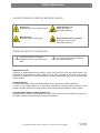
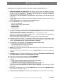
Model UVN255P SVN255P From serial # 1520001 Serial # Shipping date Installation Instructions for washers UVN255P / SVN255P © Copyright 2009, Alliance Laundry System LLC – DO NOT COPY OR TRANSMIT Cod. G522433 Rev. 00/0510 Safety Instructions 2 2 DANGER! IMPORTANT SAFETY INSTRUCTIONS WARNING: To reduce the risk of fire, electric shock or injury to persons when using the washer, follow basic precautions, including the following: 1. READ all instructions before using the washer and KEEP them in a prominent location for customer use. 2. Do not wash articles that have been previously cleaned in, washed in, soaked in, or spotted with gasoline, dry cleaning solvents, and other flammable or explosive substances. These substances GIVE OFF VAPOURS that could ignite or explode. 3. Do not add gasoline, dry-cleaning solvents, or other flammable or explosive substances to the wash water. These substances give off vapours that could ignite or explode. 4. Under certain conditions, hydrogen gas may be produced in a hot water system that has not been used for two weeks or more. HYDROGEN GAS IS EXPLOSIVE. If the hot water system has not been used for such a period, before using the washing machine, turn on all hot water faucets and let the water flow from each for several minutes. This will release any accumulated hydrogen gas. As the gas is flammable, do not smoke or use an open flame during this time. 5. Do not allow children to play on or in the washer. Close supervision of children is necessary when the washer is used near children. 6. Before the washer is removed from service or discarded, REMOVE the door. 7. Do not try to open the washer’s door if the drum is moving. 8. Do not install or store the washer where it will be exposed to the weather or near possible water splashes. 9. Do not tamper with controls. 10. Do not repair or replace any part of the washer or attempt any servicing, unless specifically recommended in the user instructions or in published user-repair instructions that you understand and have the skills to carry out. DO NOT BY-PASS any safety device. 11. DO NOT BY-PASS any safety device. It is NOT ACCEPTED ANY electric or mechanic MODIFICATION OR MANIPULATION. DO NOT INSTALL foreign components inside the machine. 12. All SAFETY INSTRUCTIONS included in the Instruction Handbooks, should be reprinted and posted in the laundry room. 13. Failure to install and operate this machine according to the Instruction Handbooks or to work safety and hygiene standards and common sense, may result in conditions which CAN PRODUCE bodily injury or loss of life. 14. The DANGER, WARNING, CAUTION and IMPORTANT instructions appearing in the Instruction Handbooks are not meant to cover all possible conditions and situations that may occur. It must be understood that common sense, caution and carefulness are factors which cannot be built into this machine. These factors MUST BE supplied by the person(s) transporting, installing, maintaining, or operating the machine. 15. All connections for electrical power and plumbing MUST comply with the statutory safety standards applicable to each country, and be made by Licensed Installers only (refer to note 3). © Copyright 2009, Alliance Laundry System LLC – DO NOT COPY OR TRANSMIT Cod. G522433 Rev. 00/0510 Safety Instructions 3 3 16. WARNING! MACHINE INSPECTION, FILTER CLEANING, MAINTENANCE, SERVICE OR PARTS REPLACEMENT Before attempting any service or inspection of the washing machine: Close and mechanically interlock the water supply valves and check that machine has COMPLETELY drained, parts have cooled down and that no pieces are in movement through inertia. To reduce the risk of electrical shock: COMPLETELY disconnect the machine from the original power source and check for accidental reconnection. MOVING THE ON SWITCH TO THE OFF POSITION IS NOT SUFFICIENT. Disconnect the electrical power of the external dosing to the washing machine. These circuits are independent of the washer’s supply. Wait a minimum of (5) five minutes after disconnection to ensure the elimination of residual voltage within the machine. Failure to comply with this warning may result in serious injury. 17. NEVER START THE MACHINE NOR USE IT IN THE ABSENCE, INCORRECT POSITION OR MALFUNCTION OF: COVERS (SAFETY GUARDS) AND PROTECTION SAFETY DEVICES CONTROL DEVICES 18. The room SHALL comply with the environment conditions (air venting, temperature, humidity...) specified in the Installation Instruction Handbook. NEVER INSTALL THE WASHING MACHINE in very humid environments or with water splashes. 19. DO NOT OPERATE the machine if it is suspected to be faulty, either visually, by noise or smell, or with missing or broken parts. 20. Machine start-up SHALL be made by Authorised Service Technicians (refer to note 2). 21. Machine SHALL BE USED by qualified personnel (refer to note 1), 1 wholly familiar with the machine’s operation. 22. DO NOT allow children or people with handicaps incompatible to machine use to operate machine. 23. Every machine working with temperature has a fire hazard, take SPECIAL care. KEEP appliance area free from combustible materials and fire extinguishers should be PLACED near the machines and should be easily accessible to all laundry staff. 24. Delimitate danger areas and PREVENT public access to them with machine in operation. Do not expose yourself to the dispenser, drain and rear overflow steam exhaust. 25. On completion of the day's work, TURN OFF the manual supply valves and DISCONNECT the electrical power by the External Automatic Switch. 26. Always CONTACT an Authorised Service Technician or Licensed Installer (refer to notes 2 & 3) about any problems or conditions you do not understand. 27. For a safe operation, machine MUST be kept in a good environment, used and maintained properly. We recommend asking annually the Authorised Technical Service for a thorough overhaul (refer to note 2). 28. The Distributor (seller) IS OBLIGED to thoroughly train the operator during the starting-up. IN THE EVENT OF THESE SAFETY INSTRUCTIONS AND ALL THE INFORMATION SUPPLIED IN THE CORRESPONDING MANUALS NOT BEING ADHERED TO, THE MANUFACTURER DECLINES ALL RESPONSIBILITY. KEEP THESE INSTRUCTIONS NOTES: (1) Qualified Personnel refers to anyone who has read the Instructions Handbooks, has been trained and has a thorough understanding of the machine’s operation (2) An Authorised Service Technician (AST) is one that has successfully completed training on the product by the manufacturer or a manufacturer Distributor. (3) An Authorised Licensed Installer is one that is suitably qualified in the procedures and regulations applicable in that country. © Copyright 2009, Alliance Laundry System LLC – DO NOT COPY OR TRANSMIT Cod. G522433 Rev. 00/0510 Safety Instructions 4 4 HAZARD SYMBOLS USED ON WASHER LABELS: Electric risk Protective guard for low voltage elements Mechanical risk Protective guard for moving parts High temperature risk Handle with caution Use suitable protection Risk of harmful vapours inhalation Keep dispenser drawer closed. Use suitable protection SYMBOLS USED IN THIS MANUAL This symbol alerts you to potential hazards for the user, the machine or the fabric. This symbol is used to give relevance to any precise explanation. Replacement Parts If literature or replacement parts are required, contact the source from which the washer-extractor was purchased or contact Alliance Laundry Systems LLC at (920) 748-3950 for the name of the nearest authorized parts distributor. A parts manual may be ordered by returning the reply card provided with each washer-extractor. Customer Service For technical assistance, contact your local distributor or call: (920) 748-3121 Ripon, Wisconsin A record of each washer-extractor is on file with the manufacturer. Always provide the machine’s serial number and model number when ordering parts or when seeking technical assistance. Refer to Figure 2. Copyright 2009, Alliance Laundry System LLC All rights reserved. No parts of the contents of this book may be reproduced or transmitted in any form or by any means without the expressed written consent of the publisher. © Copyright 2009, Alliance Laundry System LLC – DO NOT COPY OR TRANSMIT Cod. G522433 Rev. 00/0510 Safety Instructions 5 5 IMPORTANT INSTRUCTIONS FOR USE AND CONSERVATION 1. EXPECTED MACHINE USE AND DON’TS. This machine has been made and designed for industrial washing or cleansing in a water bath of linen and textile materials only. Linen and textile materials must be free from solvent impregnation or explosives. Any other use will be considered contraindicated without the written authorization of the manufacturer. Under-loading as well as overloading is not recommended. Always endeavour to meet the capacity of the machine. It is not recommended to wash the linen inside bags. Should it be necessary, load the machine up to its nominal value. It is not recommended to spin carpeting, canvas or waterproof fabrics. 2. Machine MATERIALS in contact with wash products are: Stainless Steel AISI-304 L EPOXY coating on steel (in some models) Polypropylene PP EPDM and NBR Borosilicate glass 3. The user must inquire the chemical product supplier about the risks of chemicals and its combination. The user is responsible to assure that products ARE COMPATIBLE and will not produce machine oxidation or damage either to people or to the washer. Notice that the hypochlorite (bleach), in certain conditions of use, generates chlorine gas. Chlorine is a corrosive and oxidizing substance that, in high concentrations and temperature, deteriorates the stainless steel and elastomers. There are other highly oxidizing agents, such as the ozone, that can have the same effect. 4. Periodically CLEAN the machine. You will prevent metallic parts corrosion and produce higher output and have a longer life. To clean the washing machine, use water and detergent, rinse with a damp cloth, and dry. Cleaning with water jets or pressurised steam is forbidden. 5. Once the wash cycle has finished, THE WASHER DOOR MUST REMAIN OPEN. This allows for the ventilation of the washer interior Avoids the appearance of harmful micro organisms. This extends the lifetime of the door latch. 6. NEVER use harsh products to clean the machine and laundry room. There are products on the market, which are highly corrosive. 7. If machine is left idle for long periods of time, it must be PROTECTED from humidity and temperature variations. 8. FOLLOW the fabric care instructions supplied by the manufacturer, THE MANUFACTURER REFUSES ANY RESPONSIBILITY IN CASE OF TEXTILE WEAR AND TEAR. 9. Failure due to improper machine operation may VOID WARRANTY. 10. Replacing any part of the washer can affect the machine’s safety. Examples: A screw or bolt of insufficient strength could cause dangerous damage. A heater without an internal fuse could provoke a fire. An inadequate clamp can be the cause of water leaks and short circuits... etc. The reason for which ONLY ORIGINAL SPARE PARTS MUST BE USED. Failure to take heed of this precaution may result in a washer breakdown, a serious accident, and loss of guarantee. 11. When asking for information on your machine, MENTION model and serial number (SERIAL PLATE is located at the rear side. Refer to fig. 2). 12. THE ELECTRICAL DIAGRAM IS LOCATED IN THE UNDERSIDE OF THE WASHER’S TOP COVER. © Copyright 2009, Alliance Laundry System LLC – DO NOT COPY OR TRANSMIT Cod. G522433 Rev. 00/0510 Index 6 SAFETY INSTRUCTIONS .........................................................................................................................2 INDEX.........................................................................................................................................................6 1. TECHNICAL INFORMATION .................................................................................................................7 1.1. Necessary tools for installation....................................................................................................7 1.2. Machine accessories...................................................................................................................7 1.3. Installation Specifications ............................................................................................................8 1.4. Electrical requirements..............................................................................................................11 2. TRANSPORTATION AND LOCATION .................................................................................................12 2.1. Transport of machine ................................................................................................................12 2.2. Releasing the security lock........................................................................................................13 2.3. Washer location. Conditions......................................................................................................14 2.4. Installing more than one washer................................................................................................15 2.5. Removal of shipping braces ......................................................................................................16 3. INSTALLATION ....................................................................................................................................18 3.1. Drain .........................................................................................................................................18 3.1.a. Drain to the drain box (Most recommended option)...........................................................18 3.1.b. Direct connection of the washer drain to the manifold (fig.13). .........................................18 3.2. Water inlets ...............................................................................................................................19 3.3. Electrical requirements..............................................................................................................21 3.3.1. Previous requirements.......................................................................................................21 3.3.2. Installation characteristics .................................................................................................21 3.3.3. Machine electrical connection ...........................................................................................22 3.4. Steam connection .....................................................................................................................23 3.4.1. Steam connection in TILT models .....................................................................................24 3.5. Compressed air connection (figure 20)......................................................................................25 3.6. External dosing .........................................................................................................................25 3.6.1. External dosing equipment connection to the washer........................................................25 3.6.2. Connection order of the dosing signals according to the different machine models...........28 3.6.3. External dosing hoses connection .....................................................................................29 3.7. Initial start-up.............................................................................................................................30 4. TILT MODELS.......................................................................................................................................31 4.1. TILT models specific safety instructions ....................................................................................31 4.2. TILT system description ............................................................................................................31 4.3. TILT system specific protection elements..................................................................................31 4.4. Washer location ........................................................................................................................31 4.5. 4.5. Water inlet installation proposal..........................................................................................32 5. ASSEMBLY INSTRUCTIONS FOR THE TILT SYSTEM ACCESSORIES............................................33 5.1. Parts of the tilt system assembly ...............................................................................................33 5.2. Tools to assemble the tilt system ..............................................................................................33 5.3. Tilt hinge assembly ...................................................................................................................34 5.4. Hold down base securing (figure 32).........................................................................................34 5.5. Pneumatic actuators assembly (figure 33) ................................................................................35 5.6. Position detectors assembly and adjustment (figure 43). ..........................................................35 5.7. Assembling Tilt system guards (figure 45).................................................................................36 © Copyright 2009, Alliance Laundry System LLC – DO NOT COPY OR TRANSMIT Cod. G522433 Rev. 00/0510 Technical Information 7 1. TECHNICAL INFORMATION 1.1. Necessary tools for installation 1.2. Shipping restraints ........................... flat spanner 15/16 inch (24mm) Shipping restraints ........................... offset ring wrench 15/16 inch (24mm ) Covers fixing .................................... flat spanner 3/8 inch (10mm ); 1/2 inch (13mm ) Covers fixing .................................... screwdriver Torx T20. Water inlet pipes .............................. adjustable wrench or slip-joint pliers 2.5-2.8 inch. (65-70 mm) Water and steam inlet filters............. adjustable wrench or slip-joint pliers 2.5-2.8 inch. (65-70 mm) Cable ties ......................................... socket key 7mm Electrical requirements .................... screwdriver Phillips 2. (#2) External dosing connection .............. screwdriver 3mm Machine accessories Keep all the machine’s documentation in a safe place ACCESSORY QUANTITY Set of water inlet hose filter ................ 2 (1) Steam outlet elbow ............................. 1 Steam outlet elbow clamp .................. 1 Steam inlet valve and filter (2) ............ 1 Steam inlet coupling (3)...................... 1 Fuses ................................................. (4) Installation Instructions ....................... 1 Operation Instructions ........................ 1 Parts handbook (5) ............................. 1 Other documentation ......................... (5) NOTES (1) machines with third water inlet: 3 units (2) steam connection accessories in TILT machines: refer to section 3.4. (3) Steam connection accessories in TILT machines: refer to section 3.4. (4) depending voltage on machine model and (5) depending on target country © Copyright 2009, Alliance Laundry System LLC – DO NOT COPY OR TRANSMIT Cod. G522433 Rev. 00/0510 Technical Information 1.3. 8 Installation Specifications General specifications DRUM VOLUME DRY LINEN CAPACITY BASKET WEIGHT CYLINDER: DIAMETER AND DEPTH DOOR OPENING DIAMETER MOTOR SPEC. SPIN WASHING SPEED (max) STATIC LOAD TRANSMITTED DYNAMIC LOAD TRANSMITTED DYNAMIC LOAD FREQUENCY KINETICS ENERGY MAXIMUM THERMAL SHOCK MAXIMUM SOUND LEVEL PROTECTION INDEX UNITS NO TILT dm3 (cu. ft) kg 1/10 (lbs.) kg (lbs.) kg (lbs.) mm (inch.) 1100 (38.8) 1100 (38.8) 110 (242.5) 110 (242.5) 542 (1195) 542 (1195) 1394 / 908 (54.9 / 35.7) 1394 / 908 (54.9 / 35.7) 684 (26.9) 684 (26.9) ABB. Type: MEAA 180-LB-4. Inverter duty 250/725 (46/386) 250/725 (46/386) 32 32 4855 (10703) 5208 (11482) 672 (1482) 672 (1482) 12.1 12.1 694513 694513 90 (194) 90 (194) < 70 < 70 21C 21C r.p.m. (factor G) r.p.m. kg (lbs.) kg (lbs.) Hz N xm ºC (F) dbA IP TILT Machine: dimensions and weight WITH PACKAGING WITHOUT PACKAGING H L P WEIGHT H L P M CdG K CdG J WEIGHT mm mm mm kg mm mm mm mm mm mm kg (inch.) (inch.) (inch.) (lbs.) (inch.) (inch.) (inch.) (inch.) (inch.) (inch.) (lbs.) 2245 (88.4) 1950 (76.8) 2120 (83.5) 4108 (9056) 2068 (81.4) 1770 (69.7) 1939 (76.3) 807 (31.8) 1090 (42.9) 836 (32.9) 3885 (8566) 2245 (88.4) 1950 (76.8) 2120 (83.5) 4580 (10098) 2256 (88.8) 1838 (72.4) 2058 (810) 995 (39.2) 1090 (42.9) 836 (32.9) 4238 (9343) © Copyright 2009, Alliance Laundry System LLC – DO NOT COPY OR TRANSMIT Cod. G522433 Rev. 00/0510 Technical Information 9 Machine connections A D E Ed d V AC CONNECTION H MIN/MAX PRESSURE RECOMMENDED PRESSURE FLOW) MAXIMUM TEMPERATURE thread B.S.P (NH) mm (inch.) bar (P.S.I) bar (P.S.I) l/min (Usgal/min.) ºC (ºF) 2x2 (* 1) 1955 (77.0) 0,5-6 (7-87) 2-4 (30-60) 220 (58) 80 (176) 2x2 (* 1) 2143 (84.4) 0,5-6 (7-87) 2-4 (30-60) 220 (58) 80 (176) OUTLET PIPE mm (inch.) 125 (5) 125 (5) H mm (inch.) 344 (13.5) 532 (20.9) N mm (inch.) 382 (15.0) 382 (15.0) N (2D) mm (inch.) 32 (1.3) 32 (1.3) P mm (inch.) 250 (10) 250 (10) DRAIN FLOW l/min (USgal/min) 660 (174) 660 (174) DRAIN BOX DIMENSIONS (L,P,H) mm inch. 400 x 400 x 300 (16 x 16 x 12) 400 x 400 x 300 (16 x 16 x 12) DRAIN BOX OUTLET PIPE mm (inch.) 200 (8) 200 (8) INLET FASTENING H N INLET FASTENING H N MAXIMUM VOLTAGE MAXIMUM CURRENT mm (inch.) mm (inch.) mm (inch.) CONNECTION mm (inch.) H N CONNECTION H N (MIN/MAX) PRESSURE FLOW CONNECTION H N MIN/MAX PRESSURE FLOW mm (inch.) mm (inch.) thread B.S.P (inch.) mm (inch.) mm (inch.) bar (P.S.I) kg/h (lbs/h.) thread B.S.P (inch.) mm (inch.) mm (inch.) bar (P.S.I) (Usgal/min.) 37 (1 1/2) 1890 (74.4) 825 (32.5) 16 (0.6) 1960 (77.2) 825 (32.5) 240 0.05 (* 2) 8 x diam. 10 (3/8) 1 x diam. 12 (1/2) 1305 (51.4) 775 (30.5) 1 1102 (43.4) 605 (23.8) 2-4 (29-60) 180 (397) diam.10 (3/8) 957 (37.3) 568 (22.4) 6-7 (87/100) 20 (5.3) 37 (1 1/2) 2078 (81.8) 825 (32.5) 16 (0.6) 2150 (84.6) 825 (32.5) 240 0.05 (* 2) 8 x diam. 10 (3/8) 1 x diam. 12 (1/2) 1493 (58.8) 775 (30.5) 1 1290 (50.8) 605 (23.8) mm (inch.) mm (inch.) mm (inch.) V A 2-4 (29-60) 180 (397) diam. 10 (3/8) 1145 (45.1) 568 (22.4) 6-7 (87/100) 200 (53) Environment and positioning conditions MAXIMUM TEMPERATURE MINIMUM TEMPERATURE LIGHTING VENTILATION OPENING MAXIMUM RELATIVE HUMIDITY S WORKING AREA T REAR MAINTENANCE AREA 1 ºC (ºF) Lux cm2 (sq.ft.) % mm (inch.) mm (inch.) +41 (+104) +5 (+40) 300 300 (0.4) 90 1000 (39.4) 750 (29.5) On premises with more than one washer, please refer to the corresponding dimensions in section 2.4 and fig. 7. © Copyright 2009, Alliance Laundry System LLC – DO NOT COPY OR TRANSMIT Cod. G522433 Rev. 00/0510 Technical Information 10 Legend CONNECTIONS A D 2D E Ed d V *1 *2 DIMENSIONS (figures 1, 1a, 2) Water inlets Drain Second drain Electrical connection Electrical connection for external dosing Product inlet from external dosing unit Steam inlet connection Option of 3 water inlets. Origin of the dosing signal external to the washer: maximum current 1A H N P M S T Height from the base of the machine Distance from the symmetric centre of the machine Depth Height up to lower part of door Working area Rear maintenance area Centre of gravity (CdG) OTHERS Sp Serial plate location fig 1 fig. 1a fig. 2 © Copyright 2009, Alliance Laundry System LLC – DO NOT COPY OR TRANSMIT Cod. G522433 Rev. 00/0510 Technical Information 1.4. 11 Electrical requirements In brackets: specific values for USA / CANADA VOLTAGE HEATING (*1) 200V 3ph 208V 3ph 220V 3ph 230V 3ph TOTAL POWER TOTAL CONSUMP. SWITCH CURRENT CONDUCTOR (*2) kW A A mm2 (AWG) H/V 11 31.8 40 10 x 3 + H/V 11 (11) 30.5 30.5 40 40 10 x 3 + 8 x 3 + GND H/V 11 2809 40 10 x 3 + H/V 11 27.6 40 10 x 3 + 11 26.5 40 11 26.5 40 10 x 3 + 8 x 3 + GND 240V 3ph H/V 380V 3ph H/V 11 16.7 25 6x3+ H/V 11 15.9 25 6x3+ H/V 11 15.3 25 6x3+ 11 11 11 11 14.4 14.4 13.2 13.2 20 20 20 20 400V 3ph 415V 3ph 440V 3ph H/V 480V 3ph H/V 6x3+ 10 x 3 + GND 6x3+ 10 x 3 + GND Connection table explanation and symbols (*1) HEATING H Without heating E Electric heating. Consult TOTAL ELECTRICAL POWER in the nameplate V Steam heating (*2) EXPLANATION OF CONNECTION VALUES AxB+N+ (A x B + GND) AxB+N+ AxB+N+ Conductor cross-section in mm2 (USA/CANADA: conductor cross-section in AWG) Wire number Neutral wire AxB+N+ Ground (A x B + GND) (USA/CANADA: ground) USE ONLY COPPER CONDUCTORS ch.) © Copyright 2009, Alliance Laundry System LLC – DO NOT COPY OR TRANSMIT Cod. G522433 Rev. 00/0510 Transportation and location 12 2. TRANSPORTATION AND LOCATION 2.1. Transport of machine IT IS BOUND THAT ALL MANOEUVRES ARE CARRIED OUT BY STAFF SPECIALISED IN TRANSPORT. ALWAYS USE TRANSPORT METHODS WHICH ARE SUITABLE FOR THE WEIGHT AND VOLUME OF THE WASHER. CHECK THE VALUES ON THE PACKAGING AND THE INSTALLATION SPECS (section 1.4) OF THIS MANUAL. THE WEIGHT AND VOLUME OF THESE WASHERS IS IMPORTANT. TAKE SPECIAL CARE DURING THE TRANSPORTATION OF THE MACHINE Before moving the washer, check the instructions of the packaging pictograms. Keep the washer always in an upright position. Protect the machine from rain and humidity. Avoid blows and shocks. Transporting the washer is preferably done using a forklift, raising the washer by the base. Never move the machine by pressing the sides of the packaging. Position the washer with crating as near as possible to the final location. Transporting crated machines To move the machine when crated (fig. 3) use best a forklifts, introducing the forks (A) in the space between the base of the packaging and the floor, using the maximum width permitted by the crating. In those cases in which this transport method is not possible and the machine must be lifted by a crane: fig. 3 Remove the two small covers located in the upper part of the washer (fig. 4). The transport handles are visible and accessible through the crating. ONCE THIS OPERATION IS OVER, REPLACE AND LOCK THE COVERS CORRECTLY. TRANSPORTING THE MACHINE WITHOUT PACKAGING Unpacking the machine, mainly separating from the wooden base, must be done as closely as possible to the final location. This way you will avoid damaging the base of the machine as well as the floor. Once you have separated the wooden base from the packaging, the easiest way to transport the washers is to lifting with a crane, using the transport handles as fastening points which are located at the top of the frame (fig. 5). © Copyright 2009, Alliance Laundry System LLC – DO NOT COPY OR TRANSMIT fig. 4 Cod. G522433 Rev. 00/0510 Transportation and location 13 To access these fastening points: Detach the two small covers located in the top covers, front and centre part of the washer. The transport handles are visible and accessible. ONCE THIS OPERATION IS OVER, REPLACE AND LOCK THE COVERS CORRECTLY. When there is no possible way to lift the machines in place by a crane, they must be moved by forklifts or by means of metallic rollers placed in the base of the washer (attention to the weight of the washers). The length of these rollers must be 200mm (8 inch) bigger than the base of the washer. fig. 5 2.2. Releasing the security lock In order to open the door in case of a power supply failure, completely insert a 7/64 inch (3mm) bar through the hole located on underside of the safety lock cover and at the same time turn the handle downwards. (fig.6). DANGER! MANUAL OPENING OF THE SAFETY LOCK MUST ONLY BE USED BEFORE THE START-UP OF THE WASHER. ONCE THE WASHER IS IN SERVICE, NEVER USE THE MANUAL OPENING OF THE LOCK AS A USUAL WAY TO OPEN THE DOOR. fig 6 © Copyright 2009, Alliance Laundry System LLC – DO NOT COPY OR TRANSMIT Cod. G522433 Rev. 00/0510 Transportation and location 2.3. 14 Washer location. Conditions ATTENTION! THIS WASHERS MACHINE IS A SOFT-MOUNTED MACHINES AND THE STRESS TRANSMITTED TO THE FLOOR IS LOW. HOWEVER, THEIR WEIGHT IS CONSIDERABLE. INSTALL THE WASHER ON A SECURE BASE CAPABLE OF SUSTAINING THE WASHER’S WEIGHT. REFER TO STRENGTH REQUIREMENTS TABLE (section 3.3). INSTALLATION ON NON SOLID GROUNDS AND UPPER FLOORS Do not install the machines on suspended floors or above ground level without obtaining approval from the appropriate qualified technician (structural engineer for building safety and noise transmission). See floor static & dynamic strength requirements on INSTALLATION SPECIFICATIONS (section 1.4). In these installations, the manufacturer declines all responsibility for possible damages caused by vibrations in the building structures. The floor where the washer is to be placed must be completely flat (see measures for the washer in INSTALLATION SPECIFICATIONS section 1.4). Respect the ENVIRONMENTAL CONDITIONS indicated in INSTALLATION SPECIFICATIONS (section 1.4) which refer to the working and maintenance areas; they are necessary for the comfortable use and easy maintenance of the washer. Do not install the washer in improper vented areas. Due to the products used during washing, washers may emanate vapours and gases which, in high concentrations, can be harmful for your health. TO REDUCE VIBRATION AND SOUND AND TO ENSURE THAT THE MACHINE IS CORRECTLY BALANCED, IT IS ESSENTIAL THAT THE FOUR BASE LEGS OF THE WASHING MACHINE REST UNIFORMLY UPON THE FLOOR. DO NOT PLACE ANY TYPE OF ANTI-VIBRATORY DEVICE BETWEEN THE WASHER AND THE FLOOR. NEVER INSTALL THE WASHER OVER AREAS BUILT WITH COMBUSTIBLE MATERIAL. IF WASHERS ARE INSTALLED ON METALLIC SURFACES, AN ELECTRICAL CONDUCTOR INDEPENDENT TO THE WASHER GROUND MUST GROUND THESE SURFACES. Specific warning for machines in USA /CANADA INSTALLATIONS. In order to reduce fire risk, this machine must be installed in a concrete floor without any surface treatment. WARNING! Due to design requirements, the dosing dispenser of the washer is located at a height of more than 60 inch (1500 mm). When introducing the chemical washing products in the dispenser, there is a risk, increased for users of low height, to receive spattering. As protection, it is essential to install an auxiliary platform to provide easy access and with a non-slip surface. © Copyright 2009, Alliance Laundry System LLC – DO NOT COPY OR TRANSMIT Cod. G522433 Rev. 00/0510 Transportation and location 2.4. 15 Installing more than one washer If the installation calls for more than one washer, align them with each other. The minimum distance between adjacent machines and the areas of use and maintenance (values I, S and T of fig. 7) are specified on the attached table. Check the dimensions of the drain box and the drain pipe on the table below. Location specifications (fig. 7) I DISTANCE BETWEEN MACHINES (MINIMUM) mm (inch.) 700 (27.6) S WORKING AREA mm (inch.) 1000 (39.4) T REAR MAINTENANCE AREA A DRAIN BOX DRAIN PIPE (x1; x2; x3) mm (inch.) mm (inch.) mm (inch.) 750 (29.5) 400 x 400 x 300 (H) (16 x 16 x 12 H) 180; 250; 360 (7; 10; 14) fig. 7 © Copyright 2009, Alliance Laundry System LLC – DO NOT COPY OR TRANSMIT Cod. G522433 Rev. 00/0510 Transportation and location 2.5. 16 Removal of shipping braces THIS OPERATION MUST BE CARRIED OUT BY THE AUTHORIZED TECHNICAL SERVICE. DO NOT REMOVE THE SHIPPING RESTRAINTS BEFORE PLACING THE WASHER IN ITS DEFINITIVE POSITION. NEVER START THE MACHINE UP WITHOUT FIRST REMOVING THE SHIPPING RESTRAINTS. INCOMPLIANCE WITH THIS WARNING MAY CAUSE SERIOUS PHYSICAL DAMAGES TO PEOPLE AND IRREPARABLE DAMAGE TO THE WASHER. THE WARRANTY DOS NOT COVER THIS INCIDENCE. TILT MODELS THE TILT SYSTEM ACCESSORIES MUST BE INSTALLED AFTER HAVING REMOVED THE WASHER COVERS AND BEFORE REMOVING THE TRANSPORT RESTRAINTS (Refer to chapter 4) ONCE THE TRANSPORT RESTRAINTS ARE REMOVED, REPLACE AND PROPERLY LOCKED ALL WASHER COVERS. NEVER START THE MACHINE UP OR USE IT UNTIL ALL THE COVERS HAVE BEEN REPLACED AND PROPERLY LOCKED. Remove the screws securing the side guards at the top. Loosen the screws holding the lower guard and separate them from the machine (fig. 8/A,B). fig. 8 Locate the four yellow fixing angles (fig. 9/A) and disassemble them. (In order to avoid the movement of the floating chassis during transport, the 8 fixing screws are firmly tightened. Use appropriate tools) fig. 9 © Copyright 2009, Alliance Laundry System LLC – DO NOT COPY OR TRANSMIT Cod. G522433 Rev. 00/0510 Transportation and location Assemble the rear covers. TILT MODELS. Assemble all the guards of the tilt system (section 5.7.) Assemble the toe plate (fig. 10). This item is shipped disassembled. The fixing screws are secured in the toe plate with brackets. 17 fig. 10 © Copyright 2009, Alliance Laundry System LLC – DO NOT COPY OR TRANSMIT Cod. G522433 Rev. 00/0510 Installation 18 3. INSTALLATION ALL CONNECTIONS FOR ELECTRICAL POWER AND PLUMBING MUST COMPLY WITH THE STATUTORY SAFETY STANDARDS APPLICABLE TO EACH COUNTRY, AND BE MADE BY LICENSED INSTALLERS ONLY. ALL THE WASHER CONNECTIONS MUST BE CARRIED OUT BY THE AUTHORIZED TECHNICAL SERVICE. 3.1. Drain Choose from one of the following options depending on the installation possibilities and the statutory standards applicable to the each country. 3.1.a. Drain to the drain box (Most recommended option) Build a drain box (fig. 11) following the specifications indicated in the INSTALLATION SPECS, section 1.4 Connect the drain elbow to the drain outlet and fix it with the corresponding clamp (fig. 12) The free end of the drain elbow must not be sunk in the drain box: it prevents dirty water siphoning to the washing machine it facilitates the water drain it permits to detect water leaks through the drain it prevents dirty water from coming into contact with the washer. fig 11 fig. 12 3.1.b. Direct connection of the washer drain to the manifold (fig.13). In those installations where you prefer this option to the open box option (recommended option), the following measures must be respected: Provide next to the connection point of each machine to the manifold a ventilation outlet A from the manifold to the atmosphere, set at a high of 60 inch (1500 mm) and of a diameter of 50 mm (2 inch). Diameter of the B manifold: refer to table on section 2.4. and fig. 8. The emptying of the drain trap to the sewer system is done through an open drain box (fig. 13/B and C) which prevents variations in pressure and backflow to the drain. The end of the drain trap must not be sunk in the drain box. fig. 13 © Copyright 2009, Alliance Laundry System LLC – DO NOT COPY OR TRANSMIT Cod. G522433 Rev. 00/0510 Installation 19 TILT MODELS After the starting-up of the washer, check that the loading and unloading movements don't no move the drain outlet hose out of the sewer drain box. In installation with the connection directly to the sewer, the connections of both ends of the drain hose must be fastened. 3.2. Water inlets Hoses and pipes should be flushed through before being connected to the machine. Install at each water supply and in an accessible location, a mechanically interlocked water valve. Refer to technical specifications on the INSTALLATION SPECS, section 1.4. IMPORTANT! SIPHONAGE CONTAMINATION PREVENTION If the washer extractor is directly connected to the water supply, an antisiphon device and a supplement filter must be connected either to the external supply inlet or prior to every connection. Follow the local and national regulations concerning the water supply system. IMPORTANT! PROTECTION AGAINST OVER-PRESSURES IF THE SUPPLY PRESSURE IS HIGH AND FLUID HAMMERS OCCUR WHEN CLOSING THE VALVES, WE RECOMMEND INSTALLING A SMALL AIR VESSEL OR ANTI-FLUID-HAMMER DEVICE TO PREVENT PREMATURE DAMAGE TO MEMBRANES. Assembling the filters and their connection (fig.14) Directly assemble the supplied filters to the machine water inlets. Assure they are watertight by means of a suitable product. The arrow of the filter shows the direction of water flow. Connect the hoses to the filters. Do not forget the seals. Arrangement of hoses Inlets are identified by labels posted at each inlet (fig. 15). The washer mixes hot and cold water according to the programmed temperature. The use of cold/hot water allows the machine to gain time and effectiveness in its washing programmes. Connect cold water. Inlet 1. Inlet 2. Connect hot water. Inlet 3. Connect cold or hot water according to the washer configuration. fig 14 TILT MODELS The location of the water supply must allow that hoses accommodate the washer's movements during loading and unloading operations. Refer to section 4.5. © Copyright 2009, Alliance Laundry System LLC – DO NOT COPY OR TRANSMIT Cod. G522433 Rev. 00/0510 Installation 20 fig. 15 DO NOT CONNECT THE HOT WATER TO INLET 1. THIS INLET DOES NOT HAVE A TEMPERATURE CONTROL SYSTEM. DO NOT CONNECT THE HOT WATER TO INLET 3 IF IT IS NOT CONFIGURED AS A DUAL HOT WATER INLET FLOW. INCOMPLIANCE OF THIS PRECAUTION CAN CAUSE FABRIC DAMAGE. If there is no hot water supply, connect cold water or cold softened water to inlet 2. ADAPT THE WASHER CONFIGURATION to operating with cold water. © Copyright 2009, Alliance Laundry System LLC – DO NOT COPY OR TRANSMIT Cod. G522433 Rev. 00/0510 Installation 3.3. 21 Electrical requirements 3.3.1. Previous requirements CHECK THAT THE POWER AND FREQUENCY OF THE ELECTRICAL SUPPLY CORRESPONDS TO THOSE OF THE WASHER. Check the nameplate posted on the back panel of the machine. ALL MATERIAL USED IN THE ELECTRIC INSTALLATION MUST COMPLY WITH THE REGULATIONS CURRENTLY IN FORCE IN EACH COUNTRY. ALWAYS CONNECT THE GROUND EXTERNAL PROTECTION CIRCUIT. THIS UNIT MUST BE CONNECTED TO THE GROUND INSTALLATION WITH A CONDUCTOR CONNECTED TO THE EQUIPMENT GROUNDING TERMINAL. Warning specific to machines in USA/CANADA installations. GROUNDING INSTRUCTION. This machine must be connected to a grounded metal, permanent wiring system by means of a ground cable connected to the equipment grounding terminal on the machine. 3.3.2. Installation characteristics Check the specific characteristics on the ELECTRICAL CONNECTION table (section 1.6). Conductor: Specifications referring to the conductor are based upon a multi-strand copper conductor. The length of the conductor from the safety switch to the washer must not be longer than 30 ft (10 m.) If using single-wire conductors, these must be encased within a safety conduit. The conductor must be fixed to the inlet opening of the machine using a secure connection appropriate for the type of conductor or safety conduit. The conductor must be secured against any pulling, crushing or rubbing. Additional specifications for the conductors: they must comply with the statutory regulations of the country in which it is to be installed. TILT MODELS Electrical conductors must be flexible, capable of accommodating the washer movements during the loading and unloading operations and secured at their ends. Refer to section 4.5. Circuit breaker. Install an earth-leakage protected circuit breaker. Characteristics: installed in an easily accessible place number of poles and intensity: refer to ELECTRICAL CONNECTION table (section 1.6) type A. protected against pulse currents, harmonics, the presence of continuous components... (consult manufacturer specifications) © Copyright 2009, Alliance Laundry System LLC – DO NOT COPY OR TRANSMIT Cod. G522433 Rev. 00/0510 Installation 22 Safety switch. Install an Automatic on/off Switch, outside the washer, with individual protection for each machine. Characteristics: number of poles and intensity: refer to ELECTRICAL CONNECTION table (section 1.6) C type with top opening at 0.12 inch. 3 mm must isolate electrical source phases and the N cable mechanically lockable installed in an easily accessible place ATTENTION! In machines with ETL mark, the SAFETY SWITCH must be UL489 approved. 3.3.3. Machine electrical connection Disconnect and mechanically lock the external automatic switch. FOR A CORRECT CONNECTION, FOLLOW THE INDICATIONS OF THE TABLE BELOW Disconnect and mechanically lock the external automatic switch. Open machine terminal box at the rear panel. Remove the support cover of the entry switch to the washer. On the entry hole of the electrical supply (E identified in figure 2) install a lock mechanism (not supplied with the washer) to fasten the cable or cable pipe protector, depending on the cable and pipe protector used. Refer to dimensions and connection diameter in INSTALLATION SPECS, section 1.4. Connect the wires directly to the switch breaker. The wire connection sequence to the main switch varies according to the machine connection and the power supply. This connection is indicated on the label posted next to the main switch. LABEL PE/GND L1 L2 L3 SUPPLY FEEDING CONNECTION L1 L2 L3 © Copyright 2009, Alliance Laundry System LLC – DO NOT COPY OR TRANSMIT Cod. G522433 Rev. 00/0510 Installation 3.4. 23 Steam connection Installation characteristics Before connecting the installation to the steam valve, purge the pipe conduits. Place a mechanically lockable flow valve in the steam inlet in an accessible place. Check dimensions and connection diameters in the Installation specs (section 1.4). Assemble the steam filter to the pneumatic valve inlet. Assemble the steam inlet hose to the filter inlet. Respect the steam circulation direction indicated by an arrow on each part. Connect the steam supply of the installation to the washer inlet. Safeguard the installation against accidental contact. It is advisable to insulate the installation to prevent heat loss. Open the manual valve and check for leaks in the installation. Models TILT, refer to section 3.4.1 SEAL ALL THREADED UNIONS WITH A PRODUCT WHICH IS APPROPRIATE FOR STEAM PIPE CONDUITS. ATTENTION! The admission of steam in the bath causes strong vibrations that can damage the inner drum bottom. To avoid them, the machine has a pneumatic injector device (fig. 16). To ensure its correct operation, it is VERY IMPORTANT to perform the following operations: Check that the steam inlet pressure does not exceed 4bar (60 PSI) Check that the compressed air feeding pressure is between 6 and 7bar (87-100 PSI) Adjust the compressed air injection regulator (fig. 16), during the steam intake, until noise and vibration are reduced to a minimum. Tighten A locknut to fasten the regulator position. fig. 16 © Copyright 2009, Alliance Laundry System LLC – DO NOT COPY OR TRANSMIT Cod. G522433 Rev. 00/0510 Installation 24 3.4.1. Steam connection in TILT models ATTENTION! The end of the steam supply pipe must be located in the same vertical plane as the steam inlet (V) of the washing machine. Otherwise the tilted movements cause torsion effects that can loosen the threaded couplings. The value N of figure 17 allows to locate the vertical plane of the steam inlet regarding the centre of the washer. Refer to dimensions on Installation specifications (section 1.4.) fig. 17 Connection of the machine to the steam installation (fig. 18) Accessories for the steam connection to TILT washers (some accessories can be assembled as a single set) A... steam inlet filter B... threaded coupling C... connection flexible pipe. Long.: 1500mm (59 inch) D... threaded coupling Assemble part D end with NPT thread to the steam conduits; the end with GAS thread must be connected to the flexible pipe C. Assemble the steam filter A and the coupling B to the washer steam inlet. Assemble the threaded coupling D to the steam s. Join both couplings by means of flexible pipe C. Assemble the offset end to the washer. fig. 18 Securely tighten the flexible pipe couplings. ATTENTION! DURING THIS OPERATION, HOLD THE ENDS OF THE FLEXIBLE PIPE TO PREVENT IT FROM REMAINING TWISTED (fig. 19). fig. 19 © Copyright 2009, Alliance Laundry System LLC – DO NOT COPY OR TRANSMIT Cod. G522433 Rev. 00/0510 Installation 25 3.5. Compressed air connection (figure 20) Assemble the pressure gauge A and seal the thread with Teflon or o ther sealing component. Pressure (min-max.): 6-7 bar. (87-100 PSI). The machine is provided with a filter and pressure regulator. The Compressed Air inlet connection to the machine must be done with a flexible tube of 10 mm of inner diameter, secured to the connection coupling B with a clamp. See Installation specifications (section 1.4) of the corresponding model for sections, dimensions and CA connection flow. Insert in the supply pipe and in an accessible place a MECHANICALLY LOCKABLE MANUAL SHUT-OFF VALVE, to ease general maintenance operations or to be used during long periods of non operation of the washer. VERY IMPORTANT! Although the machine is provided with a filter at the Compressed Air inlet connection, it is of vital importance to supply to the machine a completely dry air. fig 20 TILT MODELS Air connection hoses to the machine must be flexible, capable of accommodating the washer movements during the loading and unloading operations and secured at their ends. 3.6. External dosing The washer can communicate with external dosing equipment through electrical signals produced by the closure of the relay contacts during a wash cycle. The relay contacts close the circuit between a COMMON input in and each one of the outputs corresponding to each one of the dosing that the washer program runs. According to the characteristics of the external dosing equipment, two different connections can be used: Dry contacts. Origin of the dosing signals: these proceed from an external supply source of the washer (normally it is a signal coming from the external dosing equipment). The relay contacts act as dry contacts. Maximum values for the electricity supply: 240V, 50/60Hz; 1A. Contacts powered from the washer control circuit. The external dosing control board incorporates a connection point allowing to generate dosing signals from the washer control circuit. Supply voltage: 200…240V; 50/60Hz depending on the washer. Maximum connection intensity: 0.05A. 3.6.1. External dosing equipment connection to the washer Refer to the washer electrical diagram to locate the connection points. Steps prior to connection: Disconnect and mechanically lock the external automatic switch. Open the terminal box A, (figures 26 and 29) located on the back of the machine. On the entry hole of the electrical connection to the external dosing unit (identified as Ed figures 26 and 29) install a device (not supplied with the washer) to secure the cable or cable pipe protector, depending on the cable or cable pipe used. Refer to dimensions and connection diameter in INSTALLATION SPECS, section 1.4. Signal conductor Characteristics of the signal conductor cable: 0,75mm2 (#16-18 AWG), 400V. If using single-wire conductors, these must be encased within a safety conduit. The conductor must be affixed to the inlet opening of the machine affixed to the inlet opening of the machine for the type of conductor. The conductor must be protected against traction, crushing and friction. Additional specifications for the conductors: they must comply with the statutory regulations of the country in which it is to be installed. © Copyright 2009, Alliance Laundry System LLC – DO NOT COPY OR TRANSMIT Cod. G522433 Rev. 00/0510 Installation 26 TILT MODELS Electrical conductors must be flexible and capable of accommodating the washer movements during the loading and unloading operations and secured at their ends. The connection of the external dosing electrical signals takes place on the terminals of A4 and A6 boards, located at the lower part of the washer electrical box (fig. 21). If you use dosing signals coming from A-4 and A-6 board, you must link the COM terminal of each board (X6-1 and X31) by means of an electric insulation conductor of 0.75mm2 and 400V. Remove protection cover A of the connection box. Insert the conductor in Ed and secure it with the fixing device. Remove protection cover B of the electric panel. Pass the conductor through the cable ducting C Once the conductor connection is done, REPLACE AND LOCK THE COVERS CORRECTLY. fig. 21 POTENTIAL FREE RELAY CONTACTS Use of four dosing signals. The dosing signals from 1 to 4 are originated in A4 board. Connect the common dosing cable to the terminal identified as COM. Connect the cables between the washer and the dosing unit to A4 board in the order indicated in the table in section 3.6.2. (fig. 22). IMPORTANT This connection allows for the maximum strength at each of the 1A outputs. Dosing signals ARE NOT PROTECTED by the washer fuses. © Copyright 2009, Alliance Laundry System LLC – DO NOT COPY OR TRANSMIT fig. 22 Cod. G522433 Rev. 00/0510 Installation 27 RELAY CONTACTS POWERED FROM THE WASHER CONTROL CIRCUIT Use of four dosing signals The dosing signals from 1 to 4 originate from the board. Supply terminal COM from terminal X0-A of A4 board. (cable not supplied) fig. 23. Supply common phase of the signal outputs from terminal X0-B of A4board. Dosing outputs: connect in the order mentioned in the table in section 3.6.2. IMPORTANT This connection allows for the maximum strength at each of the 50mA outputs. Higher consumption can prevent the washer from functioning correctly. This connection can aggravate any problems produced by a fault in the grounding connection, both of the washer itself and of the external dosing equipment. fig. 23 USE OF MORE THAN FOUR DOSING SIGNALS Applicable in both options, for dry contacts or relay contacts supplied from the machine itself. The dosing signals from 5 to 12 are originated in A6 board (fig. 24) Supply terminal COM of A6 board from terminal X0-A of A4 board (cable not supplied). Dosing outputs: connect in the order mentioned in the table in section 3.6.2. fig. 24 © Copyright 2009, Alliance Laundry System LLC – DO NOT COPY OR TRANSMIT Cod. G522433 Rev. 00/0510 Installation 28 3.6.2. Connection order of the dosing signals according to the different machine models. Dosing signal BOARD TERMINAL COMMON A4 A4 COM 1 A4 1 2 A4 2 3 A4 3 4 A4 4 5 A6 5 6 A6 6 7 A6 7 8 A6 8 9 A6 9 10 A6 10 11 A6 11 12 A6 12 COMMON A6 COM © Copyright 2009, Alliance Laundry System LLC – DO NOT COPY OR TRANSMIT Cod. G522433 Rev. 00/0510 Installation 29 3.6.3. External dosing hoses connection The washer is supplied with a manifold with (A, fig. 25): 8 inlets with an outside diameter of 3/8 inch (10mm). 1 inlet with an outside diameter of 1/2 inch (12mm). Check dimensions of the dosing inlets in INSTALLATION SPECIFICATIONS, section 1.4. To connect the product hoses: Locate the dosing inlets in the back of the machine. Remove the tube caps and save them. Connect the hoses to the nipples of the manifold. Fasten the dosing hoses to the washing machine with the appropriate clamps. TILT MODELS Electrical conductors must be flexible and capable of accommodating the washer movements during the loading and unloading operations and secured at their ends. fig. 25 ATTENTION! To prevent undiluted chemical dripping inside the washer, all chemical supply dispensing pumps (fig. 26/A) and all dispenser tubing (fig. 26/B) must be mounted below the dosing injection point (fig.26/C) to the washer. Loops do not prevent drips. Failure to follow these instructions could damage to washer and void the warranty. fig 26 © Copyright 2009, Alliance Laundry System LLC – DO NOT COPY OR TRANSMIT Cod. G522433 Rev. 00/0510 Installation 3.7. 30 Initial start-up THE WASHER MUST BE PUT INTO SERVICE BY AN AUTHORIZED SERVICE TECHNICIAN. BEFORE THE STARTING-UP OF THE WASHER, BEAR IN MIND ALL THE SAFETY INSTRUCTIONS AT THE BEGINNING SECTION OF THIS MANUAL. Before the initial starting, make sure that you accomplish the following points: Remove all packing materials. (Break them down in order to appropriately recycle them). Remove all tools used during the installation. Verify that all accessories have been removed from the drum interior. Assemble the protective elbow at the steam exhaust facing upwards and fastened with the flange (fig. 27) Verify the correct installation of all the accessories necessary for the washer operation. Check that the electrical installation corresponds with the voltage and the frequency of the machine. Verify that the four washer feet come in contact with the floor. Verify that all the shipping restraints are removed and that all the covers are properly locked. Connect all the water, steam (steam heated washers), fig. 27 power and air compressed inlets (following machine model), according to technical specifications. Open the manual water inlet valves (steam and compressed air, following the models) and check for any leaks around the manual flow valves and connection couplings. Connect the electricity supply. Check the operation (it is recommended to use the TEST program). Keep the manual in a safe place and in good condition for its possible consultation. Before washing clothes for the first time we recommend to run a complete cycle with detergent (1/4 the normal recommended amount). Specific verification of TILT models Before starting the TILT system verification, refer to the Safety precautions specific for TILT models, at the beginning of chapter 4. Open the washer door and activate the tilt system. Verify the following points. Machine movements in the loading and unloading positions. The connections must allow the movement of the machine without damage or forced loops. Loading and unloading movements mustn't place the drain outlet hose outside the drain box or drain manifold. Tilt system limit switches must prevent the movement of the machine's rear supports while front supports are not in the rest position and vice versa. The tilt supplement guards must always prevent the access to the machine base. © Copyright 2009, Alliance Laundry System LLC – DO NOT COPY OR TRANSMIT Cod. G522433 Rev. 00/0510 Tilt models 4. 31 TILT MODELS ATTENTION! 4.1. TILT models specific safety instructions During the assembling and operation verification of the TILT system strictly follow the safety precautions indicated at the beginning of this manual. The transport and assembling operations of tilt components must be carried out by the Authorised Technical Service. Due to mass weight, be especially careful when carrying out these operations. Remember that weights and measures of TILT models can be found in the Installation specifications, section 1.4. To avoid any risk during the operation of verification of the TILT SYSTEM please follow these instructions: Keep away of the rear of the washer during the tilt movement. Because of the washer's tilting movement, there is crushing and shearing hazard between the tilting elements and the building elements. The TILT SYSTEM has JUST been designed to facilitate the washer's loading and unloading operations. DO NOT USE the washer until all the guards are properly located and adjusted In particular take special care to the tilt hinge guards. DO NOT MISLEAD NOR CANCEL THE POSITION DETECTORS located on the machine brackets. DO NOT MISLEAD NOR CANCEL THE PUSH-BUTTON that activate the drum's rotation with the door open. The pressure of the pneumatic circuit specific for tilting is controlled by a pressure regulator located on the electrical panel, with a fixed adjustment. DO NOT MODIFY NOR MANIPULATE THIS REGULATOR. Because of the facility of rotating the drum with door open, during loading and unloading operations NEVER MORE THAN ONE PERSON WILL OPERATE WITH THE MACHINE. The washer is protected against possible incorrect handling, so machine must be in horizontal position before selecting a tilting movement or starting a wash program. 4.2. TILT system description Set of components that, using the strength of two pneumatic actuators, permit a double tilt movement for the whole of the machine, forwards and backwards to easily load and unload the washer. Four position detectors, one at each washer's supports, ensure the correct operation of the tilt system, and a balanced position during the wash cycle. The washer's electrical control permits the drum's rotation and reverse by two hold-to-run push-buttons and the fabric soaking when loaded to reduce the volume. The bath used to soaking the linen is not kept inside the washer when the wash cycle starts. 4.3. TILT system specific protection elements Fixed guards: Covers at the machine sides. Protect the user from the contact with dangerous points and spattering. Moving guards: Front and side covers that permit the washer tilting. Protect the user from the contact with dangerous points and spattering. Pneumatic actuator limit switches. Prevent the excessive expansion of actuators and the excessive tilting of the washer. Position detector microswitches. Control the position of the tilt system. Pneumatic actuator pressure regulators. Limit the air pressure of pneumatic actuators. Adjustment value: 5 kg/cm2 (71 PSI). DO NOT MODIFY NOR MANIPULATE THIS REGULATOR. 4.4. Washer location To determine the washer location bear in mind the machine's tilting movements. Refer to movement values on figure 29 (section 4.5) © Copyright 2009, Alliance Laundry System LLC – DO NOT COPY OR TRANSMIT Cod. G522433 Rev. 00/0510 Tilt models 32 4.5. Water inlet installation proposal fig. 28 fig. 29 Values and symbols corresponding to the figures B C D mm 200 100 650 (inch) (8) (4) (26) mm 200 100 650 (inch) (8) (4) (26) E 300 (12) 300 (12) H (max.) 2256 (88.8) 2438 (96) N (max.) 296 (11.7) 274 (10.8) Symbols corresponding to the figures A1: A1 connection (cold water) A2: A2 connection (hot or cold water 2) A3: Independent third inlet connection (option) © Copyright 2009, Alliance Laundry System LLC – DO NOT COPY OR TRANSMIT Cod. G522433 Rev. 00/0510 Tilt system assembly 33 5. ASSEMBLY INSTRUCTIONS FOR THE TILT SYSTEM ACCESSORIES DANGER! To assemble the TILT SYSTEM elements, machine must be moved. Take special care as this machine's weight and volume is considerable. 5.1. Parts of the tilt system assembly DESCRIPTION QUANTITY Hinge assembly to the frame base (figure 31) Tilt hinge.....................................................................................................................4 Screw M14x55.......................................................................................................... 16 Self-blocking nuts M14 ............................................................................................. 16 ø 15 Washers ........................................................................................................... 32 Levelling supplement .................................................................................................. 6 Hold down base assembly (figure 32) Hold down base.......................................................................................................... 2 Hold down base.......................................................................................................... 2 ø 16 mm Metallic stud............................................................................................... 12 ø 13 x 34 Washers ................................................................................................... 12 Beam assembly to the frame (figures 33/34) Pneumatic actuator, fixing plates, beams set.............................................................. 2 M14x130 screw .......................................................................................................... 8 M14 Self-blocking nuts ............................................................................................... 8 ø 15 Washers ........................................................................................................... 16 Tilt system guards (figure 35) Front guard ................................................................................................................. 1 Rear guard ................................................................................................................. 1 Side fixing................................................................................................................... 2 5.2. Tools to assemble the tilt system To assemble the tilt supplement accessories, a part from the tools indicated in section 1.2, the following tools are required: flat spanner 7/8 inch (22 mm) offset ring wrench 7/8 inch (22mm) drill for base holding down: diam. 59 inch (17mm) © Copyright 2009, Alliance Laundry System LLC – DO NOT COPY OR TRANSMIT Cod. G522433 Rev. 00/0510 Tilt system assembly 5.3. 34 Tilt hinge assembly Lift the washer and remove the crating (refer to chapter 2 about machine's transport). Place the machine on wooden pieces (B/fig. 30) so the four supporting bases stay free and separated from the floor: value A: 8 inch (200mm) minimum. This clearance will permit the tilt hinges assembly. fig. 30 Figure 31 shows a front view of the machine's front right support Connect each of the four hinges A to each of the machine supports B. The four hinges are identical. Mounting screws D M14x55. When assembling, each wheel's shaft C remains in cross position. Take special care in aligning the hinges edges with machine supports edges. If machine needs being levelled to compensate the floor irregularities, install the levelling supplement parts E between the hinge and the machine support. fig. 31 5.4. Hold down base securing (figure 32) The arrow indicates the front of the machine. Place the holding down bases A and B on the floor where the machine is to be installed. The holding down bases are equal two against two and are matched in X form. To determine each of the four bases position, take as a reference the tilt guards supports C. Once the machine is placed on these four bases, without moving it, drill holes in the bases for holddown metallic studs; three per base. Metallic studs external diameter; 17mm. The holes must be perpendicular to the floor. Replace the metallic studs washers by the furnished washers: 13 x 34mm. Secure the bases to the floor with the metallic studs. fig. 32 © Copyright 2009, Alliance Laundry System LLC – DO NOT COPY OR TRANSMIT Cod. G522433 Rev. 00/0510 Tilt system assembly 35 5.5. Pneumatic actuators assembly (figure 33) The arrow indicates the front of the machine. The pneumatic actuators, together with the supporting plates and the beams are delivered mounted in two equal assemblies A. Steps to assemble them to the washer: To determinate the position of each of the two beams/actuator assemblies, take as a reference the two pneumatic actuator limit switches B. Place both assemblies of beams and actuators under the machine; before doing so, disassemble the two actuator limit switches B. Before disassembly, note position of the screws, separators, washers and nuts. Assemble the beams and the fixed frame. Position of screws in figure 33. Use both central screws on the left side to also secure the support plates D of the electrical installation. Connect the nylon pipes to the pneumatic fittings E. The fittings may be oriented to facilitate connection. fig. 33 Position of mounting screws of the pneumatic actuators to the fixed frame (side view). Elements of figure 42. A: Side of fixed frame B: Support beams C: Screw D: Nut E: Washers Important! The nominal tightening torque of screws M14 is 434lb. inch (5 kg.m.). If this pressure is exceeded beams may be deformed. Re-assemble the pneumatic actuator limit switches B (figure 43). fig. 34 ATTENTION! Limit switches are safety devices. Check that they are properly assembled. 5.6. Position detectors assembly and adjustment (figure 43). The position detectors A are disassembled to prevent them from being damaged during transportation. Secure them to the supports, refer to figure 43. Mounting screws: M6x15. fig. 35 © Copyright 2009, Alliance Laundry System LLC – DO NOT COPY OR TRANSMIT Cod. G522433 Rev. 00/0510 Tilt system assembly Adjustment of position detectors actuators (figure 44) The actuators C are secured to the bases through slots permitting their movement. To adjust their position: The machine must be in the rest position. Loosen mounting screws D of actuators C of position detectors. Move completely the actuators to the washer’s outside until the microswitch disconnection «click» is heard. The wheel support lever E will remain in horizontal position. Move the actuators C towards the position detectors until the microswitch connection «click» is heard and secure them in this position. (The contacts change of position is easily heard). The actuator must move the lever wheel from the position detector upwards (refer to figure). More information in the complementary schematic of TILT supplement. The schematic shows the machine in rest position. Once the position detectors actuators adjustment continue removing the transport restraints, assembling the covers and installing the machine power supplies (section 2.5). 5.7. 36 fig. 36 Assembling Tilt system guards (figure 45) The arrow indicates the front of the machine. Position the rear and front guards. They can be easily identified as the corners are folded. The rear guard is distinguished by the drain hose groove. Remove screws, washers and sleeves screwed in the hinges A from the guards, secured to each of the four bases. Put the sleeves in the holes at the guards corners. Secure them using screws and washers. The sleeves must permit the guards movement. Rectify supports position if required, by loosing the mounting screws B and move them in the appropriate direction. Engage the springs C between the base brackets and the guards brackets (two springs for each bracket). Place the side guards between the side brackets and the folded corners of the front and rear guards. Place them so that the holes match with the threaded holes at the side brackets D. Secure them with screws (M6x10). ATTENTION! Never start the machine up or use it until all the covers have been replaced and properly locked. © Copyright 2009, Alliance Laundry System LLC – DO NOT COPY OR TRANSMIT fig. 37 Cod. G522433 Rev. 00/0510