1
3. Disassembly and Reassembly
3. Disassembly and Reassembly
3.1. Precautions when replacing parts
3.1.1.
Precautions when assembling and disassembling
• Use only approved Samsung spare parts. Ensure that part number, product name, any voltage, current or temperature
rating are correct. Failure to do so could result in damage to the machine, circuit overload, fire or electric shock.
• Do not make any unauthorized changes or additions to the printer, these could cause the printer to malfunction and
create electric shock or fire hazards.
• Take care when dismantling the unit to note where each screw goes. There are 19 different screws. Use of the wrong
screw could lead to system failure, short circuit or electric shock.
• Do not disassemble the LSU unit. Once it is disassembled dust is admitted to the mirror chamber and will seriously
degrade print quality. There are no serviceable parts inside.
• Regularly check the condition of the power cord, plug and socket. Bad contacts could lead to overheating and firfe.
Damaged cables could lead to electric shock or unit malfunction.
3.1.2.
Precautions when handling PBA
Static electricity can damage a PBA, always used approved anti-static precautions when handling or storing a PBA.
• Precautions when moving and storing PBA
1) Please keep PBA in a conductive case, anti-static bag, or wrapped in aluminum foil.
2) Do not store a PBA where it is exposed to direct sunlight.
• Precautions when replacing PBA
1) Disconnect power connectors first, before disconnecting other cables.
2) Do not touch any soldered connections, connector terminals or other electronic parts when handling insulated parts.
• Precautions when checking PBA
1) Before touching a PBA, please touch other grounded areas of the chassis to discharge any static electrical charge
on the body.
2) Take care not to touch the PBA with your bare hands or metal objects as you could create a short circuit or get an
electric shock. Take extra care when handling PBAs with moving parts fitted such as sensors, motors or lamps as
they may get hot.
3) Take care when fitting, or removing, screws. Look out for hidden screws. Always ensure that the correct screw is
used and always ensure that when toothed washers are removed they are refitted in their original positions.
Copyright© 1995-2012 SAMSUNG. All rights reserved.
3-1
3. Disassembly and Reassembly
3.1.3.
Releasing Plastic Latches
Many of the parts are held in place with plastic latches. The latches break easily; release them carefully.
To remove such parts, press the hook end of the latch away from the part to which it is latched.
3-2
Copyright© 1995-2012 SAMSUNG. All rights reserved.
3. Disassembly and Reassembly
3.2. Screws used in the printer
The screws listed in the table below are used in this printer. Please ensure that, when you disassemble the printer, you keep
a note of which screw is used for which part and that, when reassembling the printer, the correct screws are used in the
appropriate places.
NOTE
This list is based on CLP-365W. So, this list may differ from your machine depending on its model.
Parts Code
Location
Description
6003-000196
FRAME-MAIN
SCREW-TAPTYPE;PWH,+,B,M3,L10,NI PLT,SWRCH18A
11
6003-000269
FRAME-MAIN
SCREW-TAPTYPE;BH,+,-,S,M3,L6,ZPC(WHT),SWRCH18A,-
13
6003-000196
FUSER
SCREW-TAPTYPE;PWH,+,B,M3,L10,NI PLT,SWRCH18A
5
6003-000282
FUSER
SCREW-TAPTYPE;BH,+,-,B,M3,L8,ZPC(BLK),SWRCH18A,-
2
6003-000152
FRAME
BASE-PAPER
PATH
SCREW-TAPTYPE;PH,+,-,B,M2,L10,ZPC(WHT),SWRCH18A,-
1
6003-000282
FRAME
BASE-PAPER
PATH
SCREW-TAPTYPE;BH,+,-,B,M3,L8,ZPC(BLK),SWRCH18A,-
4
6003-000196
FRAME
SCREW-TAPTYPE;PWH,+,B,M3,L10,NI PLT,SWRCH18A
5
6003-000269
FRAME
SCREW-TAPTYPE;BH,+,-,S,M3,L6,ZPC(WHT),SWRCH18A,-
43
6003-000301
FRAME
SCREW-TAPTYPE;BH,+,S,M4,L6,ZPC(WHT),SWRCH18A
1
6003-000269
FRAME-SUB_LEFT SCREW-TAPTYPE;BH,+,-,S,M3,L6,ZPC(WHT),SWRCH18A,-
26
6003-000269
FRAME-SUB_FRONTSCREW-TAPTYPE;BH,+,-,S,M3,L6,ZPC(WHT),SWRCH18A,-
1
6003-000196
FRAME-SUB_CTD
SCREW-TAPTYPE;PWH,+,B,M3,L10,NI PLT,SWRCH18A
2
6003-000269
FRAME-SUB
RIGHT
SCREW-TAPTYPE;BH,+,-,S,M3,L6,ZPC(WHT),SWRCH18A,-
24
6002-000440
DRIVE
SCREW-TAPPING;PWH,+,2,M3,L8,ZPC(BLK),SWRCH18A
3
6003-000269
DRIVE
SCREW-TAPTYPE;BH,+,-,S,M3,L6,ZPC(WHT),SWRCH18A,-
8
6003-000282
LSU
SCREW-TAPTYPE;BH,+,-,B,M3,L8,ZPC(BLK),SWRCH18A,-
5
6003-000196
COVER-FRONT
SCREW-TAPTYPE;PWH,+,B,M3,L10,NI PLT,SWRCH18A
5
6003-000196
COVER-REAR
SCREW-TAPTYPE;PWH,+,B,M3,L10,NI PLT,SWRCH18A
2
6003-000264
COVER-TOP
SCREW-TAPTYPE;PWH,+,-,B,M3,L6,ZPC(WHT),SWRCH18A,-
2
6003-000196
ETC
SCREW-TAPTYPE;PWH,+,B,M3,L10,NI PLT,SWRCH18A
4
6003-000269
COVER-TOP
SCREW-TAPTYPE;BH,+,-,S,M3,L6,ZPC(WHT),SWRCH18A,-
2
6003-000269
COVER-REAR
SCREW-TAPTYPE;BH,+,-,S,M3,L6,ZPC(WHT),SWRCH18A,-
4
Copyright© 1995-2012 SAMSUNG. All rights reserved.
Qty
3-3
3. Disassembly and Reassembly
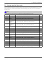
3.3. Replacing the maintenance parts
3.3.1.
ITB Unit
1. Open the front cover.
2. Remove YMCK toner cartridges and waste toner
container.
5. Open the rear cover. Release the FRAME-TRANSFER
from the left hole.
3. Remove the imaging unit.
6. Pull down the both levers.
4. Unplug the ITB connector from the top-right.
3-4
Copyright© 1995-2012 SAMSUNG. All rights reserved.
3. Disassembly and Reassembly
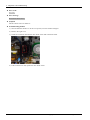
7. Remove the ITB Unit while holding its handle, and
pulling in direction of arrow.
Copyright© 1995-2012 SAMSUNG. All rights reserved.
3-5
3. Disassembly and Reassembly
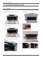
3.3.2.
Fuser Unit
1. Open the rear cover door.
2. Remove the rear cover after removing 4 screws.
4. Unplug 2 connectors from the SMPS board and main
board.
5. Remove 4 screws. And then remove the fuser unit.
3. Remove the right cover.
3-6
Copyright© 1995-2012 SAMSUNG. All rights reserved.
3. Disassembly and Reassembly
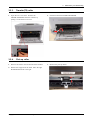
3.3.3.
Transfer(T2) roller
1. Open the rear cover door. Release the
FRAME-TRANSFER from the left hole by
pulling it to the direction of arrow.
3.3.4.
2. Push and release the FRAME-TRANSFER.
Pick up roller
1. Remove the cassette. See the bottom of the machine.
3. Remove the pick up rubber.
2. Release the stopper from the shaft. Move the right
HOUSING-PICK UP to the right.
Copyright© 1995-2012 SAMSUNG. All rights reserved.
3-7
3. Disassembly and Reassembly
3.4. Replacing the main SVC parts
NOTE
Before service, remove all toner cartridges and waste toner container.
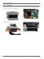
3.4.1.
Cover
1. Open the rear cover door.
4. Release the left cover.
2. Remove the rear cove after removing 4 screws.
5. Unplug the OPE connector from the main board.
Remove 2 screws. And lift up the top cover.
3. Release the right cover.
3-8
Copyright© 1995-2012 SAMSUNG. All rights reserved.
3. Disassembly and Reassembly
3.4.2.
HVPS board
1. Remove the left cover. (Refer to 3.4.1)
3. Unplug all connectors from the HVPS board.
2. Remove 5 screws. Release the lock. And release the
HVPS board.
3.4.3.
LSU
1. Remove the cassette. Stand the machine to see the
bottom.
2. Remove 3 screws. Unplug the flat cable. And release
the LSU.
Copyright© 1995-2012 SAMSUNG. All rights reserved.
3-9
3. Disassembly and Reassembly
3.4.4.
FRAME BASE-PAPER PATH
1. Remove the right cover.
4. Remove the FRAME-TRANSFER.
2. Unplug the connector from the PBA-CONNECTOR.
Remove the main board after removing 4 screws and
connectors.
5. Remove the FRAME BASE-PAPER PATH after
removing 2 screws.
3. Remove 4 screw from the bottom of the machine.
3-10
Copyright© 1995-2012 SAMSUNG. All rights reserved.
3. Disassembly and Reassembly
3.4.5.
Regi clutch and Pick up solenoid
1. Remove the FRAME BASE-PAPER PATH. (Refer to
3.4.4)
4. Release the pick up solenoid after removing 1 screw.
2. Release the regi. clutch after removing the
WASHER-PLAIN.
3. Remove 4 gears.
3.4.6.
Feed sensor and Empty sensor
1. Remove the FRAME BASE-PAPER PATH. (Refer to
3.4.4)
3. Release the Empty sensor and Feed sensor.
2. Remove the COVER-PICK UP.
Copyright© 1995-2012 SAMSUNG. All rights reserved.
3-11
3. Disassembly and Reassembly
3.4.7.
Main board
1. Remove the right cover. (Refer to 3.4.1)
3.4.8.
SMPS board
1. Remove the right cover. (Refer to 3.4.1)
2. Remove the SMPS cover after removing 2 screws.
3-12
2. Unplug all connector. Remove 4 screws. And remove
the main board.
3. Unplug all connectors on SMPS board. Remove 2
screws. And remove the SMPS board.
Copyright© 1995-2012 SAMSUNG. All rights reserved.
3. Disassembly and Reassembly
3.4.9.
Cam Solenoid
1. Remove the right and top cover. (Refer to 3.4.1)
3. Release the Cam Solenoid.
2. Remove the Cam Solenoid cover after removing 1
screw.
Copyright© 1995-2012 SAMSUNG. All rights reserved.
3-13
3. Disassembly and Reassembly
3.4.10. Main Drive Unit
1. Remove the right cover. (Refer to 3.4.1)
5. Remove 4 screws and 2 gears inside the right frame.
2. Remove the main board. (Refer to 3.4.7)
3. Remove 2 screws.
6. Release the Main Drive Unit.
4. Remove the Holder-Clutch and Holder-Gear after
removing 4 screws.
3-14
Copyright© 1995-2012 SAMSUNG. All rights reserved.
4. Alignment and Troubleshooting
4. Alignment and Troubleshooting
4.1. Alignment and Adjustments
This chapter describes the main functions for service, such as the product maintenance method, the test output related to
maintenance and repair, Jam removing method, and so on. It includes the contents of user guide.
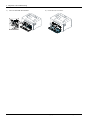
4.1.1.
Control panel
NOTE
•
This control panel may differ from your machine depending on its model. There are various types of control panels.
v
w
x
y
z
{
1
Toner LED
Shows the status of the toner.
2
Eco
Turn into eco mode to reduce toner consumption and paper usage when
pc-printing only.
3
WPS
Configures the wireless network connection easily without a computer.
(CLP-36xW only)
•
Manual print
•
Copyright© 1995-2012 SAMSUNG. All rights reserved.
Press this button each time you load a sheet of paper in the tray if
you have selected Manual Feeder for Source in your printer driver.
4-1
4. Alignment and Troubleshooting
3
Print screen
•
(CLP-36x only)
Prints the screen
•
Press this button and the green LED will start blinking. If you want
to print only the active screen, release the button when the green
LED stops blinking. If you want to print the whole screen, release
the button while it’s blinking.
•
Manual print
-
Press this button each time you load a sheet of paper in the tray
if you have selected Manual Feeder for Source in your printer
driver.
NOTE
4
Cancel
Print Screen can only be used in the Windows and Macintosh
operating systems.
-
You can only use this function with USB-connected machine.
-
When printing the active window/whole monitor screen using the
print screen button, the machine may use more toner depending on
what is being printed.
-
You can only use this function if the machine’s Easy Printer Manager
program is installed if you are a macintosh OS user, you need to
enable Screen Print Settings from the Easy Printer Manager to use
the Print Screen feature.
You can stop an operation at any time. You also can do the following functions.
•
Configuration sheet
•
•
•
Press and hold this button for about 2 seconds until the green LED
blinks slowly, and release.
Prints event log report / usage counter
•
Press and hold this button for about 4 seconds until the green LED
blinks quickly, and release.
Prints supplies info report
•
4-2
-
Press and hold this button for about 6 seconds until the green LED
on, and release.
5
Power/Wake Up
You can turn the power off or wake the machine up from the sleep mode with
this button.
6
Status LED
Shows the status of your machine
Copyright© 1995-2012 SAMSUNG. All rights reserved.
4. Alignment and Troubleshooting
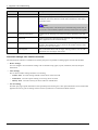
4.1.2.
Understanding the status LED
The color of the LED indicates the machine's current status.
NOTE
•
Some LEDs may not be available depending on model or country.
•
To resolve the error, look at the error message and its instructions from the troubleshooting part.
•
You also can resolve the error with the guideline from the computers’s Samsung Printing Status window.
LED
Status
Description
Status
Off
The machine is off-line or save mode.
Green
Blinking
On
Red
Blinking
On
Orange
Toner LED
Orange
Power LED
Eco
Blue
Blue
Green
The machine is receiving data from the computer.
•
The machine is printing data.
•
The machine is on-line and can be used.
The machine is on manual printing or manual duplex printing.
•
The cover is opened. Close the cover.
•
There is no paper in the tray when receiving or printing data. Load
paper in the tray.
•
The machine has stopped due to a major error.
Blinking
Upgrading firmware.
On
A paper jam has occurred.
Blinking
Small amount of toner is left in the cartridge. The estimated cartridge life of
toner is close. Prepare a new cartridge for replacement. You may temporarily
increase the printing quality by redistributing the toner.
On
WPS LED
•
•
A toner cartridge has almost reached its estimated cartridge life. It is
recommended to replace the toner cartridge.
•
The toner cartridge is not installed or the wrong toner cartridge is
installed.
Off
All toner cartridges are at normal capacity.
Blinking
The machine is connecting to a wireless network.
On
The machine is connected to a wireless network.
Off
The machine is disconnected from a wireless network.
On
The machine is in power save mode.
Off
The machine is in ready mode or the machine’s power is off.
On
Eco mode is on.
Off
Eco mode is off.
* Estimated cartridge life means the expected or estimated toner cartridge life, which indicates the average capacity of
print-outs and is designed pursuant to ISO/IEC 19798. The number of pages may be affected by operating environment,
percentage of image area, printing interval, graphics, media and media size. Some amount of toner may remain in the
cartridge even when red LED is on and the printer stops printing.
** Some LEDs may not be available depending on model or country.
Copyright© 1995-2012 SAMSUNG. All rights reserved.
4-3
4. Alignment and Troubleshooting
4.1.3.
Clearing paper jams
NOTE
To avoid tearing the paper, pull the jammed paper out slowly
and gently.
In tray1
1) Take off the cassette.
3) Reinstall the cassette.
2) Remove the jammed paper by gently pulling it straight
out.
4-4
Copyright© 1995-2012 SAMSUNG. All rights reserved.
4. Alignment and Troubleshooting
Inside the machine
CAUTION
4) Open the rear cover door.
The fuser area is hot. Take care when removing paper
from the machine.
1) Open the exit top cover.
0
5) Open the FRAME-TRANSFER.
2) Remove the jammed paper by gently pulling it straight
out.
0
6) Remove the jammed paper by gently pulling it straight
out.
3) Close the exit top cover.
If you do not see the paper in this area, stop and go to
next step:
Copyright© 1995-2012 SAMSUNG. All rights reserved.
4-5
4. Alignment and Troubleshooting
7) Close the FRAME-TRANSFER.
4-6
8) Close the rear cover door.
Copyright© 1995-2012 SAMSUNG. All rights reserved.
4. Alignment and Troubleshooting
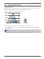
4.1.4.
Useful menu item for service
1) Altitude adjustment
Print quality is affected by atmospheric pressure, which is determined by the height of the machine above sea level. The
following information will guide you on how to set your machine for the best print quality.
Before you set the altitude value, determine the altitude where you are.
4,000 m
(13,123 ft)
1
3,000 m
(9,842 ft)
2
2,000 m
(6,561 ft)
3
1,000 m
(3,280 ft)
4
0
1
2
3
4
High 3
High 2
High 1
Normal
You can set the altitude value from Device Settings in Samsung Easy Printer Manager program.
• For Windows and Macintosh users, you set from Samsung Easy Printer Manager > Switch to advanced mode
> Device Settings.
NOTE
•
If your machine is connected to the network, you can set the altitude via SyncThru™ Web Service.
Copyright© 1995-2012 SAMSUNG. All rights reserved.
4-7
4. Alignment and Troubleshooting
4.1.5.
Periodic Defective Image
If an image defects appears at regular intervals on the printed-paper, it is due to a faulty or damaged roller. Refer to the table
below and check the condition of the appropriate roller.
Roller
Period (mm)
Phenomenon
Defective part
1
Pressure Roller
50.3mm
Background
Fuser Unit
2
Heat Roller
86.4mm
Black spot and image ghost
3
Charging Roller
37.7mm
Black Spot and line and periodic band
4
OPC Drum
188.5mm
White and Black Spots
5
Developing Roller
26.0mm
White spot, Horizontal black band
6
Supply Roller
47.5mm
Periodic Band by little difference of density
7
Transfer Roller
54.64mm
Ghost, Damaged image by abnormal transfer
4-8
Toner Cartridge
Transfer roller
Copyright© 1995-2012 SAMSUNG. All rights reserved.
4. Alignment and Troubleshooting
4.1.6.
Useful management tools
4.1.6.1.
Using Samsung Easy Printer Manager (Windows and Macintosh only)
NOTE
•
This feature may not be available depending on model or optional goods.
•
Available for Windows or Macintosh OS users only.
•
For Windows, Internet Explorer 6.0 or higher is the minimum requirement for Samsung Easy Printer Manager.
Samsung Easy Printer Manager is an application that combines Samsung machine settings into one location. Samsung
Easy Printer Manager combines device settings as well as printing environments, settings/actions and launching. All of
these features provide a gateway to conveniently use your Samsung machine. Samsung Easy Printer Manager provides two
different user interfaces for the user to choose from: the basic user interface and the advanced user interface. Switching
between the two interfaces is easy: just click a button.
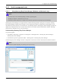
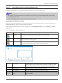
Understanding Samsung Easy Printer Manager
To open the program:
• For Windows, Select Start > Programs or All Programs > Samsung Printers > Samsung Easy Printer Manager >
Samsung Easy Printer Manager.
• For Macintosh, Open the Applications folder > Samsung folder > Samsung Easy Printer Manager.
The Samsung Easy Printer Manager interface is comprised of various basic sections as described in the table that follows:
NOTE
The screenshot may differ depending on operating system you are using.
Copyright© 1995-2012 SAMSUNG. All rights reserved.
4-9
4. Alignment and Troubleshooting
No
Area
Description
1
Printer List
The printer list displays the installed printer icons on your computer.
2
Printer Information
This area gives you general information about your machine. You can check
information, such as the machine’s model name, IP address (or Port name),
and machine status.
NOTE
Troubleshooting button: This button opens Troubleshooting Guide when an
error occurs. You can directly open the necessary section in the user’s guide.
3
Application Information
Includes links for changing to the advanced settings, preference, help, and
about.
4
Quick links
Displays Quick links to machine specific functions. This section also includes
links to applications in the advanced settings.
5
Contents Area
Displays information about the selected machine, remaining toner level,
and paper. The information will vary based on the machine selected. Some
machines do not have this feature.
6
Order Supplies
Click on the Order button from the supply ordering window. You can order
replacement toner cartridge(s) from online.
Advanced settings user interface overview
The advanced user interface is intended to be used by the person responsible for managing the network and machines.
• Device Settings
You can configure various machine settings such as machine setup, paper, layout, emulation, network, and print
information.
• Alert Settings
This is menu includes settings related to error alerting.
- Printer Alert : Provides settings related to when alerts will be received.
- Email Alert : Provides options relating to receiving alerts via email.
- History Alert : Provides a history of device and toner related alerts.
• Job Accounting
Provides querying of quota information of the specified job accounting user. This quota information can be created and
applied to devices by job accounting software such as SyncThru™ or CounThru™ admin software.
4-10
Copyright© 1995-2012 SAMSUNG. All rights reserved.
4. Alignment and Troubleshooting
4.1.6.2.
Using Samsung Printer Status (Windows only)
The Samsung Printer Status is a program that monitors and informs you of the machine status.
NOTE
•
The Samsung Printer Status window and its contents shown in this user’s guide may differ depending on the machine
or operating system in use.
•
Check the operating system(s) that are compatible with your machine.
Samsung Printer Status overview
If an error occurs while operating, you can check the error from the Samsung Printer Status. Samsung Printer Status is
installed automatically when you install the machine software.
You can also launch Samsung Printer Status manually. Go to the Printing Preferences , click the Basic tab > Printer
Status button.
These icons appear on the Windows task bar:
Icon
Mean
Description
Normal
The machine is in ready mode and experiencing no errors or warnings.
Warning
The machine is in a state where a soft error has occurred. For example, a toner low status,
which may lead to toner empty status.
Error
The machine has at least one hard error, such as out of paper, fuser error, etc. Machine
does not have ability to come to ready without customer intervention.
1
Toner Level
You can view the level of toner remaining in each toner cartridge. The machine
and the number of toner cartridge(s) shown in the above window may differ
depending on the machine in use. Some machines do not have this feature.
2
Alert Settings
Select the settings you want from the options window.
3
Order Supplies
You can order replacement toner cartridge(s) from online.
4
Troubleshooting
You can directly open the troubleshooting section in the user’s guide.
5
Close
Close the window.
Copyright© 1995-2012 SAMSUNG. All rights reserved.
4-11
4. Alignment and Troubleshooting
4.1.6.3.
Using SyncThru Web Service (SWS)
SWS is an embedded web server in the machine. This web server informs you of machine configuration, version, status and
allows you to customize the machine’s settings. You can contact this server via wired and wireless network using your
web browser in the remote place.
Connecting preparations
• Wired or Wireless Network connection is established.
• Browser (Ex> Internet Explorer) Program on your PC network connected
SWS overview
SyncThru Web Service (SWS)
• accepts HTTP request via port 80 as normal web servers.
• provides interface to users information of networked printers and allow to configure the setting of printers.
• is able to provide more complicated options than Local UI for printer configuration.
Connection Procedure
1) Open the Web-browser and input IP address of machine. Click “Login”.
2) Log-in Admin Mode. (ID: admin, PW: sec00000)
3) Select pages to check the configuration and customize the settings.
CAUTION
Please, change SWS Default ID and Password for system security in case of your first connection.
4-12
Copyright© 1995-2012 SAMSUNG. All rights reserved.
4. Alignment and Troubleshooting
4.1.7.
Updating Firmware
This chapter includes instructions for updating the printer firmware. You can update the printer firmware by using one
of the following methods :
• Update the firmware by using the USB port.
• Update the firmware by using the Network.
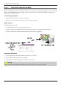
4.1.7.1.
Update the firmware by using the USB port
Upgrading preparations
• usblist2.exe : Tool which sends firmware data to printer.
• Firmware file to update.
Upgrade Procedure
1) Turn the machine off.
2) Connect USB cable to printer.
3) Turn the machine on. Check if the printer is the ready status.
4) Drag the firmware file and Drop down on the usblist2.exe.
And then firmware update will be started automatically.
5) When upgrading is completed, machine is automatically re-booting.
Copyright© 1995-2012 SAMSUNG. All rights reserved.
4-13
4. Alignment and Troubleshooting
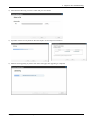
4.1.7.2.
Update the firmware by using the network (CLP-36xW only)
Upgrading preparations
• Wired or Wireless Network connection is established.
• Firmware file to update
Upgrade Procedure
1) Open the Web-browser and input IP address of machine. Click “Login”.
2) Log-in Admin Mode. (ID: admin, PW: sec00000)
3) Select Maintenance menu and click “upgrade wizard”
4-14
Copyright© 1995-2012 SAMSUNG. All rights reserved.
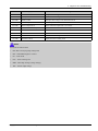
4. Alignment and Troubleshooting
4) Select firmware file using “browser” button and press next button.
5) SyncThru will check verify firmware file and compare version and press next button.
6) Machine starts upgrading. SyncThru will return home page after upgrading is completed.
Copyright© 1995-2012 SAMSUNG. All rights reserved.
4-15
4. Alignment and Troubleshooting
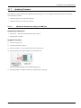
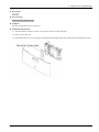
4.1.8.
EDC program
The EDC program can check the machine status and perform various test to isolate the cause of a malfunction.
1) How to use the EDC program
1) Download the EDC program in your PC.
2) Connect the printer to the computer using USB cable.
3) Turn on the printer and wait for the printer to finish initializing.
4) Start EDC program. Press the “Menu” Button
5) To exit the EDC Mode, press the “Exit” button.
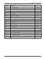
EDC mode menu (Engine Diagnostic Test)
Code-Sec
Displayed Name
Meaning
100-0000
Main BLDC Motor
Main BLDC Motor is On/Off
100-0001
Main BLDC Motor Slow
Main BLDC Motor Slow(50% speed) On/Off
100-0010
Main BLDC Motor Ready
Detect if Main BLDC Motor runs at normal speed
100-0241
Waste Toner Led
Waste Toner Led On/Off
100-0250
Waste Toner Full Sensor
Detect if the waste toner is full or not. Display Waste Tank Full adc
101-0010
T1 Pick-Up Clutch
Engages drive to pick up a paper from tray1.
101-0050
Registration Clutch
Engages drive to registartion rolls.
101-0201
Dev Cam Clutch
Rotate Deve cam
101-0202
Dev Relay1
Turn on the deve relay1
101-0203
Dev Relay2
Turn on the deve relay2
101-0204
Dev Relay3
Turn on the deve relay3
101-0205
Dev Relay4
Turn on the deve relay4
101-0210
ITB Clutch
Engages drive to ITB Cleaning Blade
101-0231
T2 Nip Release
T2 Nip Release
101-0260
Cover Open Sensor
Check if the set main cover is open or not
102-0010
T1 Paper Empty Sensor
Detect when paper is in Tray1.
102-0360
Regi. Sensor
Detect when a paper is at Regi. sensor.
102-0370
Exit Sensor
Detect when a paper is at Exit. sensor.
105-0032
MHV Bias
MHV bias voltage on at normal drive level
106-0037
Dev Bias
Dev bias voltage on at normal drive level
106-0038
Dev AC Bias
Dev bias AC voltage on at normal drive level
4-16
Copyright© 1995-2012 SAMSUNG. All rights reserved.
4. Alignment and Troubleshooting
Code-Sec
Displayed Name
Meaning
107-0032
THV Bias
THV plus bias voltage on at normal drive level
107-0033
THV(-) Bias
THV minus bias voltage on at normal drive level
107-0080
iTHV(+) Bias
iTHV plus bias voltage on at normal drive level
107-0160
Erase Lamp1
Erase Lamp 1
109-0000
Fuser Temperature A
Detects what the temperature A is on fuser.
110-0000
LSU Motor1 Run Ready
Detects if LSU motor1 runs at normal speed.
110-0060
LSU Motor1 Run
LSU Motor1 On/Off
110-0111
LSU LD Power
LSU LD Power On/Off with normal LD Power
111-0080
ID Sensor
Start ID sensor sensing On/Off
111-0090
ID Sensor Check
Display ID sensor reading value
NOTE
Acronyms and Abbreviations
•
DEV Bias- Developing High Voltage Bias
•
EDC - Embedded Diagnostic Control
•
LD – Laser Diode
•
LSU – Laser Scanning Unit
•
MHV - Main High Voltage (Charge Voltage)
•
THV - Transfer High Voltage
Copyright© 1995-2012 SAMSUNG. All rights reserved.
4-17
4. Alignment and Troubleshooting
4.2. Troubleshooting
4.2.1.
Procedure of checking the symptoms
Before attempting to repair the printer first obtain a detailed description of the problem from the customer.
Power On
OPE LED
ON?
OPE LED
Green OK?
- No Power
- Power Module error
- Main PBA
Red LED on /
Error message
is displayed.
See the troubleshooting
for error code
Print (test page)
Printing
quality is
nomal?
Refer to "Solution
of Image Problem"
END
4-18
Copyright© 1995-2012 SAMSUNG. All rights reserved.
4. Alignment and Troubleshooting
4.2.1.1.
Basic Check List
1) Check the Power.
•
Check that the power switch is turned on.
•
Check that the power cable is plugged into the outlet and the printer.
•
Check the voltage of the power outlet.
2) Check the LED of Panel.
•
Is there OPE LED ON?
›
•
If not check power cable, switch SMPS or Main board.
Is the abnormal Lamp?
›
Check the Main board and cable harness.
3) Check the Paper Path
•
Is there a Paper Jam?
›
•
Remove any paper fragments caught in the paper path.
Paper Jam occurs repeatedly at a specific point in the Paper Path
›
Open the fuser cover, Jam clear.
›
Dismantle the machine and carefully inspect the region where the jam occurs.
(Especially, check if paper fragments are caught in the Fuser
4) Print the Information Page (Configuration).
•
Try printing a test page from a computer.
›
If there is an error check cables and driver installation.
5) Check the Print Quality.
•
Is there are a Print Quality Problem?
›
Refer to image quality problem section.
6) Check consumables (toner etc.).
•
Using the keys print the Test Pattern.
›
Expected life of various consumable parts, compare this with the figures printed and replace as required
Copyright© 1995-2012 SAMSUNG. All rights reserved.
4-19
4. Alignment and Troubleshooting
4.2.2.
Error Code and Troubleshooting
Messages appear on the control panel display to indicate the machine’s status or errors. Refer to the tables below to
understand the messages’ and their meaning, and correct the problem, if necessary.
NOTE
Some messages may not appear on the display depending on the options or models.
Troubleshooting
Page
Error Code
Error Message
A1-1110
Error #A1-1110 Turn off then on
Page 4–21
A3-2210
Error #A3-2210 Call for service
Page 4–21
A3-3312
Error #A3-3312 Call for service
Page 4–22
A3-6110
Deve Home Sensor Error
Page 4–23
C1-2110
Prepare Toner
Page 4–24
C1-2120
Replace Toner
Page 4–24
C1-2411
Install toner
Page 4–24
C1-2512
Not compatible Yellow toner
Page 4–25
C1-2514
Not compatible Yellow toner
Page 4–25
C1-2711
Error: #C1-2711 Call for Service
Page 4–25
C1-2712
Error: #C1-2712 Call for Service
Page 4–25
C1-3110
Prepare Toner
Page 4–24
C1-3120
Replace Toner
Page 4–24
C1-3411
Install Toner
Page 4–24
C1-3512
Not compatible Magenta toner
Page 4–25
C1-3514
Not Compatible Magenta toner
Page 4–25
C1-3711
Error: #C1-3711 Call for Service
Page 4–25
C1-3712
Error: #C1-3712 Call for Service
Page 4–25
C1-4110
Prepare Toner
Page 4–24
C1-4120
Replace Toner
Page 4–24
C1-4411
Install Toner
Page 4–24
C1-4512
Not compatible Cyan toner
Page 4–25
C1-4514
Not compatible Cyan toner
Page 4–25
C1-4711
Error: #C1-4711 Call for Service
Page 4–25
C1-4712
Error: #C1-4712 Call for Service
Page 4–25
C1-5110
Prepare Toner
Page 4–24
C1-5120
Replace Toner
Page 4–24
C1-5411
Install Toner
Page 4–24
C1-5512
Not compatible Black toner
Page 4–25
C1-5514
Not compatible Black toner
Page 4–25
C1-5711
Error: #C1-5711 Call for Service
Page 4–25
C1-5712
Error: #C1-5712 Call for Service
Page 4–25
C3-6110
Prepare new Imaging unit
Page 4–26
4-20
Copyright© 1995-2012 SAMSUNG. All rights reserved.
4. Alignment and Troubleshooting
Troubleshooting
Page
Error Code
Error Message
C3-6120
Replace new Imaging unit
Page 4–26
C3-6410
Install Imaging unit
Page 4–26
C3-6520
Error: #C3-6520 Door open/close
Page 4–26
C5-1110
Prepare new Transfer belt
Page 4–27
C5-1120
Replace new Transfer belt
Page 4–27
C5-1710
Transfer Belt Error
Page 4–27
C5-3110
Prepare new Transfer roller
Page 4–27
C5-3120
Replace new Transfer roller
Page 4–27
C6-1110
Replace Fuser Soon
Page 4–28
C6-1120
Replace new Fuser unit
Page 4–28
C7-1131
Replace/Install Waste Toner Tank
Page 4–28
M1-1013
Paper Jam in Tray1
Page 4–29
M1-5012
Paper Empty in Tray
Page 4–30
M2-1210
Paper Jam inside machine
Page 4–29
M3-1110
Paper jam in exit area
Page 4–30
M3-2130
Output bin full Remove paper
Page 4–31
S1-5221
Wireless Network Error
Page 4–31
S2-4110
Door open Close it
Page 4–32
S2-4611
Top door Open or Exit JAM
Page 4–32
S6-3123
Network Problem:IP Conflict
Page 4–32
U1-2320
Error #U1-2320 Turn off then on
Page 4–33
U1-2330
Error #U1-2330 Turn off then on
Page 4–33
U1-2332
Error #U1-2332 Turn off then on
Page 4–33
U1-2340
Error #U1-2340 Turn off then on
Page 4–33
U2-6120
Error #U2-6120 Turn off then on
Page 4–34
U2-6140
Error #U2-6140 Turn off then on
Page 4–34
Copyright© 1995-2012 SAMSUNG. All rights reserved.
4-21
4. Alignment and Troubleshooting
► Error Code
A1-1110
► Error message
Error #A1-1110 Turn off then on
► Symptom
The main motor does not operate.
► Troubleshooting method
1) Turn the machine off then on. If the error persists, turn the machine off again.
2) Remove the rear and right cover.
3) Check if the connection between main board and main motor are correct.
4) If the connection is OK, replace the main motor.
5) If the problem persists, replace the main board.
► Error Code
A3–2210
► Error message
Error #A3-2210 Call for service
► Symptom
The CTD sensor has a problem.
► Troubleshooting method
1) Turn the machine off then on. If the error persists, turn the machine off again.
2) Check the CTD sensor connector. If the connection is OK, replace the CTD sensor board.
4-22
Copyright© 1995-2012 SAMSUNG. All rights reserved.
4. Alignment and Troubleshooting
► Error Code
A3–3312
► Error message
Error #A3-3312 Call for service
► Symptom
The outer temperature sensor is defective.
► Troubleshooting method
1) Turn the machine off then on. If the error persists, turn the machine off again.
2) Remove the front cover.
3) Disassemble the front cover and replace the PBA-DEVE CRUM JOINT that includes the outer temperature sensor.
Copyright© 1995-2012 SAMSUNG. All rights reserved.
4-23
4. Alignment and Troubleshooting
► Error Code
A3–6110
► Error message
Deve Home Sensor Error
► Symptom
The deve home sensor is defective.
► Troubleshooting method
1) Turn the machine off then on. If the error persists, turn the machine off again.
2) Remove the right cover.
3) Check the connection between the deve home sensor and connection board.
4) If the connection is OK, replace the deve home sensor.
4-24
Copyright© 1995-2012 SAMSUNG. All rights reserved.
4. Alignment and Troubleshooting
► Error Code
C1-2110
C1–3110
C1-4110
C1-5110
► Error message
Prepare Toner
► Symptom
The remaining toner cartridge is less than 10%
► Troubleshooting method
1) Print the supply information report. Check the life remaining of the toner cartridge.
2) If its life is at the end, turn the machine off and replace the toner cartridge with new one.
► Error Code
C1-2120
C1-3120
C1-4120
C1-5120
► Error message
Replace Toner
► Symptom
The toner cartridge is at the end of its life.
► Troubleshooting method
1) Turn the machine off and replace the toner cartridge with new one.
► Error Code
C1–2411
C1–3411
C1–4411
C1–5411
► Error message
Install toner
► Symptom
The toner cartridge is not installed or the CRUM has some problem.
► Troubleshooting method
1) Check if the toner cartridge is installed properly. Turn the machine off then on.
2) If the error message is not disappear, remove the toner cartridge. Thoroughly roll the cartridge five or six times to
distribute the toner evenly inside the cartridge. And reinstall the toner cartridge.
3) If the problem persists, check that the CRUM contact area is contaminated. Clean it.
4) If the problem persists, replace the toner cartridge with new one.
Copyright© 1995-2012 SAMSUNG. All rights reserved.
4-25
4. Alignment and Troubleshooting
► Error Code
C1-2512
C1-2514
C1-3512
C1-3514
C1-4512
C1-4514
C1-5512
C1-5514
► Error message
Not compatible Yellow toner
Not compatible Magenta toner
Not compatible Cyan toner
Not compatible Black toner
► Symptom
Toner cartridge is not compatible.
► Troubleshooting method
1) If the toner cartridge is not a Samsung genuine toner cartridge, replace with new one.
► Error Code
C1–2711
C1–2712
C1–3711
C1–3712
C1–4711
C1–4712
C1–5711
C1–5712
► Error message
Error: #C1-2711 Call for Service
Error: #C1-2712 Call for Service
Error: #C1-3711 Call for Service
Error: #C1-3712 Call for Service
Error: #C1-4711 Call for Service
Error: #C1-4712 Call for Service
Error: #C1-5711 Call for Service
Error: #C1-5712 Call for Service
► Symptom
CRUM chip is defective.
► Troubleshooting method
1) Check if the toner cartridge is installed properly. Turn the machine off then on.
2) If the problem persists, check that the CRUM contact area is contaminated. Clean it.
4-26
Copyright© 1995-2012 SAMSUNG. All rights reserved.
4. Alignment and Troubleshooting
3) If the problem persists, replace the toner cartridge with new one.
► Error Code
C3-6110
C3-6130
► Error message
Prepare new Imaging unit
Replace new Imaging unit
► Symptom
The imaging unit is at the end of its life.
► Troubleshooting method
1) Print the supply information report. Check the life remaining of the imaging unit.
2) If its life is at the end, turn the machine off and replace the imaging unit with new one.
► Error Code
C3-6410
C3-6520
► Error message
Install Imaging unit
Error: #C3-6520 Door open/close
► Symptom
The imaging unit is not installed.
► Troubleshooting method
1) Open the front cover. Remove YMCK toner cartridges.
2) Check if the imaging unit is installed. Remove and reinstall it.
3) If the problem persists, replace the imaging unit.
Copyright© 1995-2012 SAMSUNG. All rights reserved.
4-27
4. Alignment and Troubleshooting
► Error Code
C5-1110
C5-1120
► Error message
Prepare new transfer belt unit.
Replace new transfer belt unit.
► Symptom
The ITB Unit is at the end of its life.
► Troubleshooting method
1) If its life is at the end, turn the machine off and replace the ITB unit with new one.
► Error Code
C5-1710
► Error message
Transfer Belt Error
► Symptom
ITB home sensor is defective.
► Troubleshooting method
1) Turn the machine off then on.
2) If the problem persists, turn the machine off. Remove and reinstall the ITB unit.
3) If the problem persists, replace the ITB unit with new one.
► Error Code
C5-3110
C5-3120
► Error message
Prepare new Transfer roller
Replace new Transfer roller
► Symptom
The transfer roller is at the end of its life.
► Troubleshooting method
1) If its life is at the end, turn the machine off and replace the transfer roller Assy with new one.
4-28
Copyright© 1995-2012 SAMSUNG. All rights reserved.
4. Alignment and Troubleshooting
► Error Code
C6-1110
C6-1120
► Error message
Prepare new fuser unit.
Replace with new fuser unit.
► Symptom
The fuser unit is at the end of its life.
► Troubleshooting method
1) Print the supply information report. Check the life remaining of the fuser unit.
2) If its life is at the end, turn the machine off and replace the fuser unit with new one.
► Error Code
C7-1311
► Error message
Waste toner container is not installed. Install it.
► Symptom
The waste toner container is not installed
► Troubleshooting method
1) Check if the waste toner container is installed properly.
2) Remove and reinstall the waste toner container.
Copyright© 1995-2012 SAMSUNG. All rights reserved.
4-29
4. Alignment and Troubleshooting
► Error Code
M1–1013
M2–1210
► Error message
Paper jam in tray 1.
Paper Jam inside machine
► Symptom
The jammed paper has occurred in the tray1 or inside the machine.
► Troubleshooting method
1) Remove the jammed paper.
2) If the jammed paper occurs continually, check the followings.
a) Check if the pick up roller are worn out or contaminated. Clean the contaminated part or replace it.
b) Check if the feed actuator or feed sensor is assembled correctly.
3) If the pick up solenoid is defective, replace it.
4-30
Copyright© 1995-2012 SAMSUNG. All rights reserved.
4. Alignment and Troubleshooting
► Error Code
M1–5012
► Error message
Paper Empty in Tray
► Symptom
Paper is empty in tray.
► Troubleshooting method
1) Remove the cassette. Check if the paper is loaded.
2) If the problem persists, replace the paper empty sensor.
► Error Code
M3–1110
► Error message
Paper jam in exit area.
► Symptom
The jammed paper has occurred in the exit area.
► Troubleshooting method
1) Remove the jammed paper.
2) If the problem persists, check the following.
a) Check if there is any obstacles or paper on the paper path. Remove it.
b) Check if the fuser unit is assembled properly. If the fuser unit is defective, replace it.
Copyright© 1995-2012 SAMSUNG. All rights reserved.
4-31
4. Alignment and Troubleshooting
► Error Code
M3–2130
► Error message
Output bin full Remove paper
► Symptom
The paper is full on the exit tray.
► Troubleshooting method
1) Remove the paper.
2) If the problem persists, remove the top cover.
3) Check if the bin full sensor connector is connected properly.
4) If the connection is OK, replace the bin full sensor.
► Error Code
S1-5221
► Error message
Wireless Network Error
► Symptom
The communication error between the main board and WLAN board has occurred.
► Troubleshooting method
1) Turn the machine off then on. If the problem persists, turn the machine off.
2) Remove the right cover. Check the connection between the main board and WLAN board.
3) If the connection is OK, replace the WLAN board.
4-32
Copyright© 1995-2012 SAMSUNG. All rights reserved.
4. Alignment and Troubleshooting
► Error Code
S2–4110
► Error message
Door is open. Close it.
► Symptom
Door is opened or the cover open switch is defective.
► Troubleshooting method
1) Check if the front cover is closed perfectly.
2) If the error persists, check that the cover-open sensor is working normally. If it is defective, replace it.
► Error Code
S2–4611
► Error message
Top door Open or Exit JAM
► Symptom
Top door is opened or the paper jam has occurred in exit area.
► Troubleshooting method
1) Open and close the top door.
2) If there is a jammed paper, remove it.
3) Open and close the top door again.
► Error Code
S6-3123
► Error message
Network Problem:IP Conflict
► Symptom
IP address conflicts with that of other system.
► Troubleshooting method
1) Change the machine’s IP address.
2) Check the setting-up for 802.1x confirmation server.
Copyright© 1995-2012 SAMSUNG. All rights reserved.
4-33
4. Alignment and Troubleshooting
► Error Code
U1–2320
U1–2330
U1–2332
U1–2340
► Error message
Error #U1-2320 Turn off then on
Error #U1-2330 Turn off then on
Error #U1-2332 Turn off then on
Error #U1-2340 Turn off then on
► Symptom
The temperature control of fuser unit is abnormal.
► Troubleshooting method
1) Check if the input voltage is normal.
2) Turn the machine off. Remove and reinstall the fuser unit. Be careful when connecting the AC-connector and
Thermistor connector.
3) Turn the machine on. Is the error message is disappeared?
4) Check the followings. If the fuser unit has any problem, replace it.
a) Check if the fuser connector is connected properly.
b) Check if the halogen lamp voltage is normal.
c) Check if the thermistor is contaminated or twisted.
5) If the problem persists, replace the main board or SMPS board.
4-34
Copyright© 1995-2012 SAMSUNG. All rights reserved.
4. Alignment and Troubleshooting
► Error Code
U2-6120
U2-6140
► Error message
Error #U2-6120 Turn off then on
Error #U2-6140 Turn off then on
► Symptom
LSU Motor does not work normally. / LSU Hsync signal is abnormal.
► Troubleshooting method
1) Check if the LSU harness on the main board is connected properly.
2) If it is OK, check that the LSU harness on LSU board is connected properly.
3) Check if the LSU harness is defective.
4) If the problem persists, replace the LSU.
5) If the problem persists after replacing LSU, replace the main board.
Copyright© 1995-2012 SAMSUNG. All rights reserved.
4-35
4. Alignment and Troubleshooting
4.2.3.
Image quality problems
1) Vertical Black Line and Band
•
Description : Straight thin black vertical line occurs in the printed image.
Cause and Check Point
Solution
Check if the surface of the charge roller is scratched or
contaminated.
Replace the imaging unit and test again.
Check if there are grooves on the circumference of the
OPC drum.
Replace the imaging unit and test again.
Check if the cleaning blade is damaged
Replace the imaging unit and test again.
Check if paper transfer belt is damaged or contaminated.
Replace the ITB unit and test again.
2) Vertical White Line
•
4-36
Description : White vertical voids in the image.
Cause and Check Point
Solution
Check if the LSU window or internal lenses of LSU is
contaminated.
Clean the LSU window with recommended cleaner(IPA).
Clean the window with a clean cotton swab. If dirt is
inside the LSU, replace the LSU.
Check if there are scratches on the circumference of the
OPC drum.
Replace the imaging unit and test again.
Check if there are scratches on the circumference of the
developing roller.
Replace the toner cartridge and test again.
Check if paper transfer belt is damaged or contaminated.
Replace the ITB unit and test again.
Copyright© 1995-2012 SAMSUNG. All rights reserved.
4. Alignment and Troubleshooting
3) Contamination on back of page
•
Description : The back of the page is contaminated.
Cause and Check Point
Solution
Dirty registration roller, pressure roller, feed roller, etc.
Any dirty rollers through the path of the paper.
Identify the roller which may cause the problem by
comparing the period of the contamination on images with
the size of rollers. Clean any dirt from the roller or replace
the dirty roller.
Check if the transfer roller is damaged or contaminated.
Replace the transfer roller and test again.
Check if paper transfer belt is damaged or contaminated.
Replace the ITB unit and test again.
4) Dark or Black image
•
Description : The black page is printed out.
Cause and Check Point
Solution
No charging voltage in the HVPS.
Check the connecting state between the Main PBA and
HVPS. Reconnect the harness.
Poor contact between toner cartridge and set contacts.
Clean the contacts as necessary. Replace any deformed
or damaged contacts.
HVPS is defective.
Replace the HVPS.
Copyright© 1995-2012 SAMSUNG. All rights reserved.
4-37
4. Alignment and Troubleshooting
5) Blank Page
•
Description : Blank page is printed.
Cause and Check Point
Solution
Bad contacts from OPC drum and/or toner cartridge to
ground.
Check the terminal of Ground-OPC.
Not working the LSU.
Check the connector of LSU.
Not working the developing bias voltage on HVPS.
Replace the HVPS.
6) Uneven Density
•
4-38
Description : Print Density is uneven between left and right.
Cause and Check Point
Solution
The life of the Toner Cartridge has expired.
Replace the toner cartridge.
The pressure force in the left and right springs of the ITB
unit is not even.
Replace the ITB Unit
Copyright© 1995-2012 SAMSUNG. All rights reserved.
4. Alignment and Troubleshooting
7) Horizontal Bands
•
Description : Dark or white horizontal stripes appear in the page. (These may occur at regular intervals down the
page.)
Cause and Check Point
Solution
The developing roller, OPC drum or other rollers in the
toner cartridge may be contaminated or deformed.
Replace the imaging unit.
Bad contacts of HV terminals of the toner cartridge with
high voltage terminals from printer set.
Clean all HV terminals in the cartridge and on the set
frame. Ensure all toner or paper dust, particles are
removed.
8) Poor Fusing
•
Description : Toner is not properly fixed on paper.
Cause and Check Point
Solution
The media doesn’t meet specification
Use the proper media in specifications.
Fuser is defective
Replace the fuser unit.
Copyright© 1995-2012 SAMSUNG. All rights reserved.
4-39
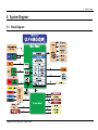
5. System Diagram
5. System Diagram
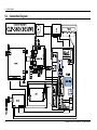
5.1. Block Diagram
Blo c k Dia g ra m o f
CLP -360/365(W)
OP E P a ne l & Dis pla y
LED & Ke ys
2p
Front Cove r ope n
P olygon Motor
AR M9 Þ 300 MHz
16p
5p
2p
T1
T2
4p
CHARGER
De ve S upply
De ve Bia s
De ve Dr.Bla de
3p
Ma in Bo a rd
14p
27p
LS U
HVP S
Te mu jin -C
9p
LD Bãã d
Was te Toner
TX & R X
EXIT s ens or
2p
R AM controller
(Imbedded 32MB R AM)
ER AS ER
14p
R J45
GP IO
10 /100 LAN
*
+24 V / +5V
S MP S
Re a r Cove r ope n
14p
C ontrol S ignal
EEP R OM
8KB/32 KB*
Fus er AC
2p
FUS ER
2p
nSS , MOSI, SCK,MISO
C R UM Y
C R UM M
C R UM C
C R UM K
4p
4p
4p
4p
OP C Key
ADC 5 C H
UAR T
P WM 8 C H
I2 C
LS U
controller
S tep Motor
HP VC
SCL
S erial
Flas h
2 MB/8 MB*
LAMP
Thermis tor
SDA
MAC
4p
US B DEVIC E
BLDC
Motor
(MAIN)
10p
Image P roces s or
Local controller
US B 2 .0
2p
T2 clutch
P LL
SPI
CRUM
J oint
&
Oute r
TEMP
11p
ITB HOME s ens or
& Inner TEMP .
3p
DEVE HOME s ens or
2p
6p
DEVE clutch
6p
Conne ction I/F Boa rd
2p
C TD
24p
W-LAN
Module
2p
2p
Copyright© 1995-2012 SAMSUNG. All rights reserved.
Empty s ens or
3p
R egi s ens or
ITB clutch
5p
5p
3p
P ickup clutch
2p
R egi clutch
5-1
5. System Diagram
5.2. Connection Diagram
Co n n e c t io n Dia g r a m o f
MT
BLDC
OP E
CLP-3 6 0 / 3 6 5 (W)
1
2
3
4
5
6
7
8
9
10
FUS ER
000000000000000000000000
000000000000000000000000
000000000000000000000000
1
2
3
4
5
6
7
8
9
10
11
12
13
14
OPE
CL
CL
DEVE HOME
Sens or
C ONNEC TION
CTD
Clutch
1
2
1
2
3
4
5
6
7
8
9
10
11
12
13
14
CL
1
2
3
4
5
6
REGI
Clutch
1
2
3
4
5
24 VF
THV_C LUTC H
DGND
DGND
CN1 2
PICKUP
T2 CLUTCH
CL
ERASER
REGI / EMPTY
SENSOR
LD
TEMUJ IN-C
LAN
(W model only )
US B
SMPS Powe r
1
2
3
4
5
6
7
8
9
10
11
12
13
14
1
2
3
4
5
6
7
8
9
10
11
12
13
14
1
2
3
4
MAIN
CN14
CN6
SINGLE BEAM LSU
3_ 3V_LS U
nHS YNC
DGND
VDO_ 1_P
VDO_ 1_N
DGND
nLDON_ LS U
nS H_ LS U1
LD_P OWE R
C LK_ LS U_MOT
nR E ADY_ LS U
nLS U_ MOT _ E N
DGND
24 VA
FUS E R_ THE R M1
FUS E R_ TR _ B AS E
DGND
DGND
CN11
1
2
3
4
5
6
7
8
9
10
11
12
13
14
15
16
DE VE_ C LUTC H
ITB _ C LUTC H
24 VF
24 VF
P IC KUP_ C LUTC H
R E GI_C LUTC H
DE VE_ HOME
3 _ 3V_S E NS OR
3 _ 3V_ITB _HOME
nS E NS_ ITB _HOME
INNE R _ TE MP
DGND
C TD_ LE D
ADC _C TD_ S
5 V_C TD
ADC _C TD_ P
OUT_ TE MP
S C L0 _C R UM
OP C _KE Y
3 _ 3_ C R UM
S DA0 _C R UM
nS E NS_ P_R E GI
DGND
nS E NS_ P_E MR TY
CONNECTION
SMPS Powe r
24 VF
24 VF
nDE V_E N
3.3 V
nC OVE R_S W
P WM_ DE V_ DC
WAS TE_ TX
P WM_ DE V_ AC
WAS TE_ LE VE L
THV_R E AD
DGND
DGND
nS E NS_P _E XIT
P WM_ DE V_ VP P
P WM_ MHV
P WM_ THV
5V
P WM_ ITHV
3_ 3V_ S E NS OR
nTHV_ E N
ITHV_ R E AD
DE V_ R E LAY3
DE V_ R E LAY1
DE V_ R E LAY2
E R AS E R_LAMP
DE V_ R E LAY4
CN10
FUSER
AC
LS U
1
2
3
4
5
6
7
8
9
1
2
3
4
5
6
7
8
9
10
11
12
13
14
15
16
17
18
19
20
21
22
23
24
25
26
27
HVP S / Wa ste / Era s er
S MP S
P -MOTOR
1
2
3
4
5
A
C
1
2
3
4
5
6
7
8
9
10
11
12
13
14
15
16
17
18
19
20
21
22
23
24
2
1
2
3
4
5
6
7
8
9
10
11
12
13
14
15
16
17
18
19
20
21
22
23
24
25
26
27
1
REAR
COVER
HVPS / Wa ste / Era se r
3 .3V
DGND
S CK
DGND
MIS O
nINT_WLAN
nS S1 _WLAN
DGND
MOS I
3 .3V_P ull Up
W-LAN Module
(W Mode l only)
CL
CN10
OPE
1
2
3
4
5
6
7
8
9
10
11
CN7
HVP S
CN4
CN1 / WLAN_SPI
nCRUM/
OPC KEY
B LDC _ C LK
nB LDC _ MOTOR _R E ADY
nB LDC _ MOTOR _E N
DGND
DGND
DGND
24VF
24VF
FUS ER
1
2
3
4
5
1
2
3
4
5
6
7
8
9
10
CN5
ITB HOME
Se nsor
BLDC
CONNE CTION
WASTE
TONER
1
2
3
4
5
6
7
8
9
10
11
12
13
14
15
16
17
18
19
20
21
22
23
24
P OWE R _SW
O P_ P OWER _LE D
LE D_Y_ E MP TY
LE D_M_ E MP TY
LE D_C _ EM PTY
LE D_K_ E MP TY
DGND
n KE Y_ E CO
LE D_EC O
LE D_R EADY
LE D_ER R OR
LE D_WLAN
n KE Y_ P RT _ SC R E EN
n KE Y_ C ANC E L
EXIT
Se nsor
DEVE
Clutch
FUSE R _ ON
2 4 VF
EN_ R E ALY_ AC
2 4 V_ON_ OF F
DGND
5 V_ S MP S
5 V_ S MP S
DGND
2 4 VA
2 4 VA
2 4 VA
DGND
DGND
DGND
ITB
Clutch
FRONT
COVER
220 V/
110 V
5-2
Copyright© 1995-2012 SAMSUNG. All rights reserved.
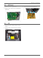
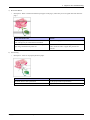
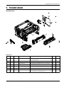
Exploded Views and Parts List
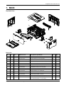
1. MAIN
Exploded View
Parts List
No.
Lvl.
1
Loc.
Material Code
Description & Specification
SNA
1
JC90-01142A
CASSETTE; CLP-365W,SEC
SA
1
2
2
JC95-01585A
COVER-FRONT; CLP-365W,SEE
SA
1
3
2
JC63-03531A
COVER-LEFT; CLP-365W,HIPS,2.0T,266.5,209.
SA
1
4
2
JC63-03567A
COVER-RIGHT; CLP-365W,HIPS,2.0T,266.5,209
SA
1
5
2
JC95-01588A
COVER-REAR; CLP-365,SEE,SPLIT GRAY
SA
1
6
2
JC63-01574A
COVER-CABLE; CLP-310,POM,T1.5,19.7,37.3,H
SA
1
7
2
JC96-06298A
CARTRIDGE-WTB; CLP-365W,SEC
SA
1
8
1
JC96-06292B
CARTRIDGE-TRANSFER; CLP-365W,SEC
SNA
1
9
1
JC93-00728A
FRAME-MAIN; CLP-365W,SEC
SNA
1
10
1
JC95-01589B
COVER-TOP; CLP-365,SEE
SA
1
11
1
JC93-00708A
FRAME-TRANSFER; CLP-365
SA
1
12
1
JC44-00214A
SMPS-V2; CLP-365W,Carlsen,Flyback,60W,220
SA
1
13
1
JC92-02485C
PBA-MAIN;
CLP-360,XEV,MAIN,71.75*120,FR4,
SA
1
H4282
Copyright© 1995-2012 SAMSUNG. All rights reserved.
Qty.
1
Exploded Views and Parts List
2
Copyright© 1995-2012 SAMSUNG. All rights reserved.
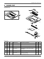
Exploded Views and Parts List
2. COVER-TOP
Exploded View
Parts List
No.
Lvl.
0
Loc.
Material Code
Description & Specification
SNA
1
JC95-01589B
COVER-TOP; CLP-365,SEE
SA
1
1
2
JC63-03533A
COVER-DUST; CLP-365W,HIPS,2.0T,229.9,70.8
SNA
1
2
2
JC63-03534A
COVER-JAM; CLP-365W,HIPS,2.0T,228.6,67.8,
SNA
1
3
2
JC63-03536B
COVER-TOP; CLP-365,HIPS,2.5T,378,305,SEE,
SNA
1
4
2
JC67-00603A
MACHINERY ETC-PMO SUB STACKER;
CLP-365W,P
SNA
2
5
2
JC63-03569A
COVER-EXIT; CLP-365W,ABS+PC,2.0T,240,32.5
SNA
1
6
2
JC61-05006A
STACKER-MAIN; CLP-360,HIPS,136,118.9,HB,B
SA
1
7
2
JC63-03568A
COVER-TOP DUMMY;
CLP-365W,HIPS,2.0T,287.2
SNA
1
Copyright© 1995-2012 SAMSUNG. All rights reserved.
Qty.
3
Exploded Views and Parts List
No.
Lvl.
8
Material Code
Description & Specification
SNA
2
JC92-02500A
PBA-OPE; CLP-360,SEC,44*126.8 mm,Basic,FR
SA
1
9
2
JC64-00755A
KEY-PRINT SCREEN; CLP-365W,HIPS,13.6,1.3T
SA
1
10
2
JC63-03535A
COVER-KEY-HOLDER;
CLP-365W,HIPS,1.5T,115.
SNA
1
4
Loc.
Qty.
Copyright© 1995-2012 SAMSUNG. All rights reserved.
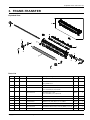
Exploded Views and Parts List
3. FRAME-TRANSFER
Exploded View
Parts List
No.
Lvl.
0
Loc.
Material Code
Description & Specification
SNA
1
JC93-00708A
FRAME-TRANSFER; CLP-365
SA
1
1
2
JC66-03353A
ROLLER-TRANSFER; Calsen,18.0
(mm),NBR+ECO
SA
1
2
2
JC70-10232A
IPR-PLATE SAW; ML-80,SUS304 CSP 1/2H,T0.1
SNA
1
3
2
JC61-05658A
HOLDER-SHAFT L;
CLP-365,POM,2.0,16,23,WHI
SNA
1
4
2
JC61-05655A
HOLDER-TR CAM;
CLP-365,HIPS,2,11,16,BLACK
SNA
2
5
2
6107-001542
SPRING-ES; SWP,PI0.45,L34.1,ID3,OD3.9
SNA
2
6
2
JC66-03789A
CAM-TR R; CLP-365,POM,2.0,30,WHITE,HB
SNA
1
7
2
6107-003276
SPRING-CS; SWP B,0.9,12,12.1,FREE
SNA
1
8
2
JC67-00671A
COUPLER-TR; CLP-365,POM,13,WHITE
SNA
1
9
2
JC61-04156A
HOLDER-SAW PLATE; CLP-325,HIPS,1.2,9.6,21
SNA
1
10
2
JC66-03788A
CAM-TR L; CLP-365,POM,2,20,WHITE,HB
SNA
1
D1171
Copyright© 1995-2012 SAMSUNG. All rights reserved.
Qty.
5
Exploded Views and Parts List
No.
Lvl.
11
12
6
Loc.
Material Code
Description & Specification
SNA
Qty.
2
6107-003280
SPRING-TS; SWP,ZINC WHITE,0.8,25/16,8,RIG
SNA
1
2
JC61-04944A
HOLDER-CHARGE;
CLP-360,BRONZE-SINTERED
SNA
1
Copyright© 1995-2012 SAMSUNG. All rights reserved.
Exploded Views and Parts List
4. CASSETTE
Exploded View
Parts List
No.
Lvl.
0
Loc.
Material Code
Description & Specification
SNA
1
JC90-01142A
CASSETTE; CLP-365W,SEC
SA
1
1
2
JC61-04940A
PLATE-KNOCKUP;
CLP-360,HIPS,GRAY,GUIDE SU
SA
1
2
2
JC61-04937A
GUIDE-ADJUST CASSETTE L;
CLP-360,HIPS,GRA
SNA
1
3
2
JC61-04936A
GUIDE-ADJUST CASSETTE R;
CLP-360,HIPS,GRA
SNA
1
4
2
G1521
6107-001240
SPRING-CS; SUS304-WPB,GROUND
END,PI0.6,D1
SA
2
5
2
B1072
JC61-02127A
GUIDE-KNOCKUP L;
SCX-4500,POM,NTR,GUIDE
SA
1
6
2
JC73-00322B
RUBBER-PAD_FRICTION;
ML-1660,EPDM,80,0.6~
SNA
1
Copyright© 1995-2012 SAMSUNG. All rights reserved.
Qty.
7
Exploded Views and Parts List
No.
Lvl.
Loc.
Material Code
Description & Specification
SNA
7
2
G1358
JG61-70531A
SPRING ETC-LOCKER,PLATE;
SF6000,SUS304WPB
SA
2
8
2
B1073
JC61-02128A
GUIDE-KNOCKUP R;
SCX-4500,POM,NTR,GUIDE
SA
1
9
2
JC66-03004A
GEAR-PINION;
ML-2950ND,POM,0.5,32,3.9,WHI
SNA
1
10
2
JC61-04951A
FRAME-SEMI CASSETTE;
CLP-360,HIPS,GRAY,CA
SNA
1
11
2
JC61-04935A
SUPPORT-CASSETTE EXTENSION;
CLP-360,HIPS,
SNA
1
12
2
JC61-04934A
STOPPER-PAPER REAR; CLP-360,HIPS,GRAY
SNA
1
13
2
JC63-03487A
COVER; CLP-360,PC,GRAY
SA
1
8
Qty.
Copyright© 1995-2012 SAMSUNG. All rights reserved.
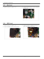
Exploded Views and Parts List
5. FRAME-MAIN
Exploded View
Parts List
No.
Lvl.
1
Loc.
Material Code
Description & Specification
SNA
2
JC44-00215A
HVPS; 24V,21.6V~27.6V,MAX
5KV,MAX-2KV,600
SA
2
2
JC93-00734A
FRAME-TERMINAL; CLP-365W,SEC
SNA
3
2
JC93-00547A
FRAME BASE-PAPER PATH; CLP-365W,SEC
SA
1
4
2
JC91-01080A
FUSER; CLP-365W,SEC,WORLD,220V
SA
1
5
3
JC97-04058A
LSU; CLP-365W,SEC,Single,A4(Ltr),600,S2,7
SA
1
6
2
JC93-00729A
FRAME; CLP-365W,SEC
SNA
1
7
2
JC92-02489A
PBA-CONNECTOR;
CLP-365W,SEC,CONNECTION,45
SA
1
Copyright© 1995-2012 SAMSUNG. All rights reserved.
Qty.
1
15
9
Exploded Views and Parts List
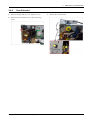
5.1. FUSER
Exploded View
Parts List
No.
Lvl.
0
2
1
4
2
Material Code
Description & Specification
SNA
JC91-01080A
FUSER; CLP-365W,SEC,WORLD,220V
SA
1
JC66-02716B
ROLLER-PRESSURE;
ML-1660,SUM22,6,237.5,BL
SA
1
4
JC61-04989A
GUIDE-INPUT;
CLP-365W,PET+GF,LV2550GN30,P
SNA
1
3
4
1404-001740
THERMISTOR-NTC ASSY;
7Kohm,3370K,0.3mW/C,
SNA
1
4
4
JC66-03355A
GEAR-FUSER;
CLP-365W,PPS,1,34,BROWN,36,13
SNA
1
5
4
JC61-04984A
BUSH-PR R;
CLP-365W,PPS,6.1,BLACK,SEC,RBA
SNA
1
6
4
JC66-03326A
ROLLER-HEAT;
CLP-360,SILICON,24.3,RED,ETC
SNA
1
10
Loc.
L9622
Qty.
Copyright© 1995-2012 SAMSUNG. All rights reserved.
Exploded Views and Parts List
No.
Lvl.
7
Loc.
Material Code
Description & Specification
SNA
4
4713-001662
LAMP-HALOGEN; 230V,850W
SNA
1
8
4
4712-001091
THERMOSTAT; AC125/250V,195+-5100
SNA
1
9
4
JC61-02423A
SPRING ETC-EXIT; CLP-310,SUS304 WPB,PI0.3
SA
2
10
4
JC66-03359A
ACTUATOR-EXIT;
CLP-365W,PA,BLACK,ACTUATOR
SNA
1
11
4
6107-001507
SPRING-TS;
SUS304,NATURAL,PI0.25,W5.3,ID4
SA
1
12
4
JC61-04990A
GUIDE-OUTPUT;
CLP-365W,PET+GF,41.1,GF30%,
SNA
1
13
4
JC66-03871A
ROLLER-PRESSURE SHAFT;
CLP-365W,SUM22,9.6
SNA
1
14
4
JC63-03522A
COVER-UPPER; CLP-365W,PC,SEC,NH-1035
SNA
1
15
4
JC61-04987A
FRAME-LOWER;
CLP-365W,PET+GF,LV2550GN30,B
SNA
1
16
4
JC67-00674A
CAP-RESISTOR; CLP-365W,PC,46,14.7
SNA
1
17
4
JC39-00521A
CBF HARNESS-FUSER REC;
SCX-5530FN,CBF,UL3
SA
1
18
4
JC39-01701A
HARNESS-FUSER AC;
CLP-365W,UL3398,2p,BLK,
SNA
1
L7112
L7540
H2699
Copyright© 1995-2012 SAMSUNG. All rights reserved.
Qty.
11
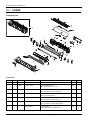
Exploded Views and Parts List
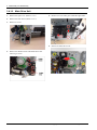
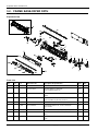
5.2. FRAME BASE-PAPER PATH
Exploded View
Parts List
No.
Lvl.
0
Material Code
Description & Specification
SNA
2
JC93-00547A
FRAME BASE-PAPER PATH; CLP-365W,SEC
SA
1
1
3
JC98-01960A
BOARD-EMPTY SENSOR;
CLP-360W,SEC,Photo-In
SNA
1
1-1
4
JC92-02508A
PBA-EMPTY SENSOR; CLP-365W,SEC,EMPTY
SENS
SNA
2
2
3
JC66-03321A
ACTUATOR-FEED;
CLP-360,ABS+PC,BLACK,ACTUA
SA
1
3
3
JC93-00549A
DRIVE-PICK UP; CLP-365W,SEC
SA
1
4
3
JC33-00025B
SOLENOID-MANUAL; SCX-5135ND,DC
24V,120ohm
SA
1
5
5
JC47-00033C
CLUTCH-ELECTRIC; 2.5,36,0.6,120mA,200Ohm
SA
1
6
3
JC66-03824A
GEAR-RDCN PH 3; CLP-365W,POM,M0.8 /
M0.6,
SNA
1
7
3
JC66-03825A
GEAR-RDCN PICK-UP; CLP-365W,POM,M0.6
/ M0
SNA
1
12
Loc.
L6828
Qty.
Copyright© 1995-2012 SAMSUNG. All rights reserved.
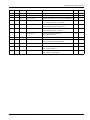
Exploded Views and Parts List
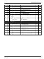
No.
Lvl.
8
Loc.
Material Code
Description & Specification
SNA
3
JC66-03826A
GEAR-RDCN REGI; CLP-365W,POM,M0.6 /
M0.6,
SNA
1
9
3
JC66-03813A
GEAR-IDLE REGI;
CLP-365W,POM,M0.6,Z35,NAT
SNA
1
10
3
JC61-01548A
HOLDER-M-CAM; CLP-300,POM
(DE8903),18.5,2
SA
1
11
3
JC61-05049A
HOLDER-SHAFT IDLE;
CLP-365W,POM,NATURAL
SNA
2
12
3
6107-001309
SPRING-CS; SWP-B,PI0.5,L10,ID4.0,OD5.0
SA
2
13
4
JC39-01704A
HARNESS-COVER S/W;
CLP-365W,UL10272,2p,BL
SA
1
14
3
JC93-00555A
FRAME BASE-HOLDER PAD; CLP-365W,SEC
SNA
1
15
3
JC66-03322A
ACTUATOR-EMPTY;
CLP-360,ABS+PC,BLACK,ACTU
SA
1
16
3
JC66-03317A
ROLLER-REGI; CLP-360,EPDM,SUM22,6
SA
1
17
3
JC66-03899A
SHAFT-FEED IDLE_C; CLP-360,SUM 22,237,8.0
SNA
1
18
3
JC61-05648A
GUIDE-PATH LOWER;
CLP-365W,ABS,1.5,20,222
SNA
1
19
3
JC93-00553A
FRAME BASE-PICK UP; CLP-365W,SEC
SA
1
19-1
4
JC61-01714A
STOPPER-PICK_UP L;
ML-2571N,POM,D17,20,NA
SA
1
19-2
4
JC61-05815A
HOUSING-PICKUP A;
CLP-365W,ABS+PC,25.7,32
SA
1
19-3
4
JC61-02389A
HOUSING-PICKUP B; CLP-310,POM F20-02,1.0,
SA
1
19-4
4
JC66-03786A
CAM-CTD;
CLP-365W,POM,1.2,NATURAL,Right
SNA
1
19-5
4
JC73-00309A
RUBBER-PICK_UP; CLP-310,EPDM
SA
1
C5143
L7445
G1665
C5342
Copyright© 1995-2012 SAMSUNG. All rights reserved.
Qty.
13
Exploded Views and Parts List
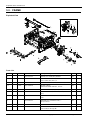
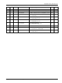
5.3. FRAME
Exploded View
Parts List
No.
Lvl.
1
4
1-1
5
1-2
5
1-3
5
2
3
3
Material Code
Description & Specification
SNA
JC93-00714A
DRIVE; CLP-365W,SEC,WORLD
SA
1
JC92-01986A
PBA SUB-DEVEHOME;
CLP-310,SEC,SEC,FR-1,1L
SA
1
JC47-00033C
CLUTCH-ELECTRIC; 2.5,36,0.6,120mA,200Ohm
SA
1
L9654
JC31-00091B
MOTOR BLDC;
48M843D010B/BL55K-M01,1443.82
SA
1
H3697
JC47-00007F
CLUTCH-ITB CAM; 8,33,0.8,133mA,180Ohm
SA
2
3
JC66-03829A
GEAR-RDCN PH 2; CLP-365W,POM,M0.5 /
M0.8,
SA
1
4
3
JC66-03828A
GEAR-RDCN T2 CAM; CLP-365W,POM,M0.5
/ M0.
SA
1
5
4
JC32-00014A
SENSOR-CTD; SENSOR-CTD,0 ~
60,5V,6.62mA,r
SA
1
6
4
0604-001415
PHOTO-INTERRUPTER; TR,DIP-4,BK
SA
1
7
4
JC39-01704A
HARNESS-COVER S/W;
CLP-365W,UL10272,2p,BL
SA
1
14
Loc.
K4920
L9633
Qty.
Copyright© 1995-2012 SAMSUNG. All rights reserved.
Exploded Views and Parts List
No.
Lvl.
8
Loc.
Material Code
Description & Specification
SNA
3
JC91-01078A
FUSER-ROLLER EXIT; CLP-360,SEC,WORLD
SA
1
9
3
JC61-05650A
GUIDE-CASSETTE L; CLP-365W,HIPS,1.5,33.86
SNA
1
10
3
JC61-05649A
GUIDE-CASSETTE R; CLP-365W,HIPS,1.5,35.85
SNA
1
11
3
JC61-05677A
GUIDE-BASE FRONT HINGE;
CLP-365W,HIPS,2,3
SA
1
12
3
JC61-05753A
HOLDER-CLUTCH_ITB;
CLP-365W,ABS,2,45,54.8
SNA
1
13
3
JC61-05758A
HOLDER-T2 CLUTCH;
CLP-365W,HIPS,2,85.1,69
SNA
1
14
3
JC61-04960A
HOUSING-HARNESS;
CLP-365W,HIPS,2.0T,BLACK
SNA
1
15
3
JC61-05647A
GUIDE-PATH UPPER; CLP-365W,HIPS,1.5,30.35
SNA
1
16
3
JC66-03790A
SHAFT-COUPLER;
CLP-365,POM,52,17,WHITE,HB
SNA
1
17
3
JC66-03349A
SHAFT-ITB CLEAN CAM C;
CLP-365W,POM,L47.1
SNA
1
Copyright© 1995-2012 SAMSUNG. All rights reserved.
Qty.
15