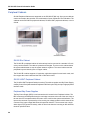
1
jfqbi
puJOMM=fm=`çããìåáÅ~íáçåë=mä~íÑçêã
dÉåÉê~ä=fåÑçêã~íáçå=dìáÇÉ
oÉäÉ~ëÉ=RKM=roN
NOTICE
The information contained in this document is believed to be accurate in all respects but
is not warranted by Mitel Networks™ Corporation (MITEL®). The information is subject
to change without notice and should not be construed in any way as a commitment by
Mitel or any of its affiliates or subsidiaries. Mitel and its affiliates and subsidiaries assume
no responsibility for any errors or omissions in this document. Revisions of this document
or new editions of it may be issued to incorporate such changes.
No part of this document can be reproduced or transmitted in any form or by any
means - electronic or mechanical - for any purpose without written permission from
Mitel Networks Corporation.
Trademarks
SX-200, SX-2000, Superset, MiTAI, ACD TELEMARKETER, Speak@Ease,
SUPERCONSOLE 1000, Mitel Express Messenger, and NuPoint Messenger are
trademarks of Mitel Networks Corporation.
VT100 is a trademark of Digital Equipment Corporation
Windows is a trademark of Microsoft Corporation
CENTREX is a trademark of Western Electric Company.
Symbol, the Symbol logo and Spectrum24 are registered trademarks of Symbol
Technologies, Inc.
SpectraLink NetLink e340, h340, 640 Wireless Telephones are trademarks of
SpectraLink Corporation.
Other product names mentioned in this document may be trademarks of their respective
companies and are hereby acknowledged.
SX-200 IP Communications Platform (ICP)
General Information Guide
Release 5.0 UR1
October 2009
®,™ Trademark of Mitel Networks Corporation
©Copyright 2009, Mitel Networks Corporation
All rights reserved
Table of Contents
About this document . . . . . . . . . . . . . . . . . . . . . . . . . . . . . . . . . . . . . . . . . . . . . . . . . . . . . . . . . . . . 1
Audience . . . . . . . . . . . . . . . . . . . . . . . . . . . . . . . . . . . . . . . . . . . . . . . . . . . . . . . . . . . . . . . . . . . 1
About the SX-200 ICP documentation . . . . . . . . . . . . . . . . . . . . . . . . . . . . . . . . . . . . . . . . . . . . . 1
What’s new? . . . . . . . . . . . . . . . . . . . . . . . . . . . . . . . . . . . . . . . . . . . . . . . . . . . . . . . . . . . . . . . . 2
Release 5.0 UR1 . . . . . . . . . . . . . . . . . . . . . . . . . . . . . . . . . . . . . . . . . . . . . . . . . . . . . . . . . . 2
Release 5.0 . . . . . . . . . . . . . . . . . . . . . . . . . . . . . . . . . . . . . . . . . . . . . . . . . . . . . . . . . . . . . . 2
Release 4.0 UR5 . . . . . . . . . . . . . . . . . . . . . . . . . . . . . . . . . . . . . . . . . . . . . . . . . . . . . . . . . . 2
Release 4.0 . . . . . . . . . . . . . . . . . . . . . . . . . . . . . . . . . . . . . . . . . . . . . . . . . . . . . . . . . . . . . . 2
Release 3.1 . . . . . . . . . . . . . . . . . . . . . . . . . . . . . . . . . . . . . . . . . . . . . . . . . . . . . . . . . . . . . . 3
Release 3.0 . . . . . . . . . . . . . . . . . . . . . . . . . . . . . . . . . . . . . . . . . . . . . . . . . . . . . . . . . . . . . . 3
Release 2.3 . . . . . . . . . . . . . . . . . . . . . . . . . . . . . . . . . . . . . . . . . . . . . . . . . . . . . . . . . . . . . . 4
Release 2.2 . . . . . . . . . . . . . . . . . . . . . . . . . . . . . . . . . . . . . . . . . . . . . . . . . . . . . . . . . . . . . . 4
Release 2.1 . . . . . . . . . . . . . . . . . . . . . . . . . . . . . . . . . . . . . . . . . . . . . . . . . . . . . . . . . . . . . . 5
Overview. . . . . . . . . . . . . . . . . . . . . . . . . . . . . . . . . . . . . . . . . . . . . . . . . . . . . . . . . . . . . . . . . . . . . 7
Mitel SX-200 IP Communications Platform . . . . . . . . . . . . . . . . . . . . . . . . . . . . . . . . . . . . . . . . . 7
System . . . . . . . . . . . . . . . . . . . . . . . . . . . . . . . . . . . . . . . . . . . . . . . . . . . . . . . . . . . . . . . . . . . . . 11
System architecture . . . . . . . . . . . . . . . . . . . . . . . . . . . . . . . . . . . . . . . . . . . . . . . . . . . . . . . . . . 11
SX-200 ICP Controller . . . . . . . . . . . . . . . . . . . . . . . . . . . . . . . . . . . . . . . . . . . . . . . . . . . . . . . . 12
CX/CXi Controllers . . . . . . . . . . . . . . . . . . . . . . . . . . . . . . . . . . . . . . . . . . . . . . . . . . . . . . . . 12
AX Controller . . . . . . . . . . . . . . . . . . . . . . . . . . . . . . . . . . . . . . . . . . . . . . . . . . . . . . . . . . . . 15
MX Controller . . . . . . . . . . . . . . . . . . . . . . . . . . . . . . . . . . . . . . . . . . . . . . . . . . . . . . . . . . . . 17
Comparison of SX-200 ICP MX, CX/CXi, and AX controllers . . . . . . . . . . . . . . . . . . . . . . . . 19
Network Services Units . . . . . . . . . . . . . . . . . . . . . . . . . . . . . . . . . . . . . . . . . . . . . . . . . . . . . . . 23
Analog Services Unit . . . . . . . . . . . . . . . . . . . . . . . . . . . . . . . . . . . . . . . . . . . . . . . . . . . . . . . . . 24
Analog Services Unit II . . . . . . . . . . . . . . . . . . . . . . . . . . . . . . . . . . . . . . . . . . . . . . . . . . . . . . . 24
Peripheral Cabinets . . . . . . . . . . . . . . . . . . . . . . . . . . . . . . . . . . . . . . . . . . . . . . . . . . . . . . . . . . 26
SX-200 ELx Cabinet . . . . . . . . . . . . . . . . . . . . . . . . . . . . . . . . . . . . . . . . . . . . . . . . . . . . . . . 26
SX-200 LIGHT Peripheral Cabinet . . . . . . . . . . . . . . . . . . . . . . . . . . . . . . . . . . . . . . . . . . . . 26
Peripheral Bay Power Supplies . . . . . . . . . . . . . . . . . . . . . . . . . . . . . . . . . . . . . . . . . . . . . . 26
Peripheral Interface Cards and Modules . . . . . . . . . . . . . . . . . . . . . . . . . . . . . . . . . . . . . . . 27
Manufacture discontinued or unsupported devices . . . . . . . . . . . . . . . . . . . . . . . . . . . . . . . 29
Desktop Devices . . . . . . . . . . . . . . . . . . . . . . . . . . . . . . . . . . . . . . . . . . . . . . . . . . . . . . . . . . . . 29
Digital Services Cards and Modules . . . . . . . . . . . . . . . . . . . . . . . . . . . . . . . . . . . . . . . . . . . . . 29
Network . . . . . . . . . . . . . . . . . . . . . . . . . . . . . . . . . . . . . . . . . . . . . . . . . . . . . . . . . . . . . . . . . . . 32
ISDN (Integrated Services Digital Network) . . . . . . . . . . . . . . . . . . . . . . . . . . . . . . . . . . . . . 33
IP Networking . . . . . . . . . . . . . . . . . . . . . . . . . . . . . . . . . . . . . . . . . . . . . . . . . . . . . . . . . . . . 35
Ethernet WAN and LAN interfaces . . . . . . . . . . . . . . . . . . . . . . . . . . . . . . . . . . . . . . . . . . . . 36
Internet Gateway (CXi only) . . . . . . . . . . . . . . . . . . . . . . . . . . . . . . . . . . . . . . . . . . . . . . . . . 36
Embedded firewall (CXi only) . . . . . . . . . . . . . . . . . . . . . . . . . . . . . . . . . . . . . . . . . . . . . . . . 36
iii
SX-200 ICP General Information Guide
Directed Data I/O . . . . . . . . . . . . . . . . . . . . . . . . . . . . . . . . . . . . . . . . . . . . . . . . . . . . . . . . . 37
Desktop Devices . . . . . . . . . . . . . . . . . . . . . . . . . . . . . . . . . . . . . . . . . . . . . . . . . . . . . . . . . . . . . . 39
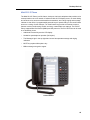
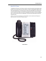
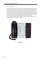
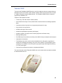
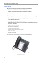
IP Phones . . . . . . . . . . . . . . . . . . . . . . . . . . . . . . . . . . . . . . . . . . . . . . . . . . . . . . . . . . . . . . . . . 41
Mitel 5304 IP Phone . . . . . . . . . . . . . . . . . . . . . . . . . . . . . . . . . . . . . . . . . . . . . . . . . . . . . . . 42
Mitel 5312 IP Phone . . . . . . . . . . . . . . . . . . . . . . . . . . . . . . . . . . . . . . . . . . . . . . . . . . . . . . . 43
Mitel 5324 IP Phone . . . . . . . . . . . . . . . . . . . . . . . . . . . . . . . . . . . . . . . . . . . . . . . . . . . . . . . 44
Mitel 5330 IP Phone . . . . . . . . . . . . . . . . . . . . . . . . . . . . . . . . . . . . . . . . . . . . . . . . . . . . . . . 45
Mitel 5340 IP Phone . . . . . . . . . . . . . . . . . . . . . . . . . . . . . . . . . . . . . . . . . . . . . . . . . . . . . . . 46
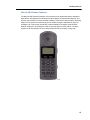
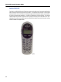
NetLink i640 Wireless Telephone . . . . . . . . . . . . . . . . . . . . . . . . . . . . . . . . . . . . . . . . . . . . . 47
NetLink e340/h340 . . . . . . . . . . . . . . . . . . . . . . . . . . . . . . . . . . . . . . . . . . . . . . . . . . . . . . . . 48
Telematrix 3000IP . . . . . . . . . . . . . . . . . . . . . . . . . . . . . . . . . . . . . . . . . . . . . . . . . . . . . . . . . 49
Accessories for IP Phones . . . . . . . . . . . . . . . . . . . . . . . . . . . . . . . . . . . . . . . . . . . . . . . . . . . . . 50
Cordless Handset and Headset . . . . . . . . . . . . . . . . . . . . . . . . . . . . . . . . . . . . . . . . . . . . . . 51
Mitel IP Programmable Key Modules . . . . . . . . . . . . . . . . . . . . . . . . . . . . . . . . . . . . . . . . . . 52
Line Interface Module . . . . . . . . . . . . . . . . . . . . . . . . . . . . . . . . . . . . . . . . . . . . . . . . . . . . . . 53
Mitel IP Paging Unit . . . . . . . . . . . . . . . . . . . . . . . . . . . . . . . . . . . . . . . . . . . . . . . . . . . . . . . 54
Conference Phones . . . . . . . . . . . . . . . . . . . . . . . . . . . . . . . . . . . . . . . . . . . . . . . . . . . . . . . . . . 55
Mitel 5310 IP Conference Unit . . . . . . . . . . . . . . . . . . . . . . . . . . . . . . . . . . . . . . . . . . . . . . . 55
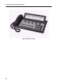
Digital Phones . . . . . . . . . . . . . . . . . . . . . . . . . . . . . . . . . . . . . . . . . . . . . . . . . . . . . . . . . . . . . . 56
5540 IP Console . . . . . . . . . . . . . . . . . . . . . . . . . . . . . . . . . . . . . . . . . . . . . . . . . . . . . . . . . . . . 57
Accessories for Superset 4000 Series Digital Phones . . . . . . . . . . . . . . . . . . . . . . . . . . . . . . . . 59
Mitel Programmable Key Module 12 . . . . . . . . . . . . . . . . . . . . . . . . . . . . . . . . . . . . . . . . . . . 59
Mitel Programmable Key Module 48 . . . . . . . . . . . . . . . . . . . . . . . . . . . . . . . . . . . . . . . . . . . 60
Mitel PKM Interface Module . . . . . . . . . . . . . . . . . . . . . . . . . . . . . . . . . . . . . . . . . . . . . . . . . 60
Mitel Analog Interface Module . . . . . . . . . . . . . . . . . . . . . . . . . . . . . . . . . . . . . . . . . . . . . . . 61
Music-On-Hold/Pager Unit (DMP) . . . . . . . . . . . . . . . . . . . . . . . . . . . . . . . . . . . . . . . . . . . . . . . 62
Power Accessories . . . . . . . . . . . . . . . . . . . . . . . . . . . . . . . . . . . . . . . . . . . . . . . . . . . . . . . . . . 63
SX-200 ICP . . . . . . . . . . . . . . . . . . . . . . . . . . . . . . . . . . . . . . . . . . . . . . . . . . . . . . . . . . . . . . 63
IP Phones . . . . . . . . . . . . . . . . . . . . . . . . . . . . . . . . . . . . . . . . . . . . . . . . . . . . . . . . . . . . . . . 63
Peripheral Cabinets . . . . . . . . . . . . . . . . . . . . . . . . . . . . . . . . . . . . . . . . . . . . . . . . . . . . . . . 63
Migration . . . . . . . . . . . . . . . . . . . . . . . . . . . . . . . . . . . . . . . . . . . . . . . . . . . . . . . . . . . . . . . . . . . . 65
Management and Maintenance . . . . . . . . . . . . . . . . . . . . . . . . . . . . . . . . . . . . . . . . . . . . . . . . . . 67
Customer Data Entry (CDE) . . . . . . . . . . . . . . . . . . . . . . . . . . . . . . . . . . . . . . . . . . . . . . . . . . . 67
Maintenance Terminal . . . . . . . . . . . . . . . . . . . . . . . . . . . . . . . . . . . . . . . . . . . . . . . . . . . . . . . . 69
Applications . . . . . . . . . . . . . . . . . . . . . . . . . . . . . . . . . . . . . . . . . . . . . . . . . . . . . . . . . . . . . . . . . 73
Feature packages . . . . . . . . . . . . . . . . . . . . . . . . . . . . . . . . . . . . . . . . . . . . . . . . . . . . . . . . . . . 73
ACD TELEMARKETER . . . . . . . . . . . . . . . . . . . . . . . . . . . . . . . . . . . . . . . . . . . . . . . . . . . . 73
Centralized Voice Mail . . . . . . . . . . . . . . . . . . . . . . . . . . . . . . . . . . . . . . . . . . . . . . . . . . . . . 74
iv
Table of Contents
Hotel/Motel . . . . . . . . . . . . . . . . . . . . . . . . . . . . . . . . . . . . . . . . . . . . . . . . . . . . . . . . . . . . . . 74
MiteI Express Messenger . . . . . . . . . . . . . . . . . . . . . . . . . . . . . . . . . . . . . . . . . . . . . . . . . . 74
Property Management System . . . . . . . . . . . . . . . . . . . . . . . . . . . . . . . . . . . . . . . . . . . . . . 75
Station Message Detail Recording . . . . . . . . . . . . . . . . . . . . . . . . . . . . . . . . . . . . . . . . . . . . 75
Tenanting . . . . . . . . . . . . . . . . . . . . . . . . . . . . . . . . . . . . . . . . . . . . . . . . . . . . . . . . . . . . . . . 76
Traffic Measurement and IP Trunk Performance . . . . . . . . . . . . . . . . . . . . . . . . . . . . . . . . . 76
Embedded applications . . . . . . . . . . . . . . . . . . . . . . . . . . . . . . . . . . . . . . . . . . . . . . . . . . . . . . . 76
Embedded Voice Mail . . . . . . . . . . . . . . . . . . . . . . . . . . . . . . . . . . . . . . . . . . . . . . . . . . . . . 77
Applications . . . . . . . . . . . . . . . . . . . . . . . . . . . . . . . . . . . . . . . . . . . . . . . . . . . . . . . . . . . . . . . . 81
Mitel Teleworker Solution . . . . . . . . . . . . . . . . . . . . . . . . . . . . . . . . . . . . . . . . . . . . . . . . . . . 81
Mitel Customer Interaction Solutions (formerly 6100) . . . . . . . . . . . . . . . . . . . . . . . . . . . . . 82
Mitel Call Accounting . . . . . . . . . . . . . . . . . . . . . . . . . . . . . . . . . . . . . . . . . . . . . . . . . . . . . . 83
Mitel Speech-Enabled Applications (formerly 6500) . . . . . . . . . . . . . . . . . . . . . . . . . . . . . . 83
Unified Messaging - Standard . . . . . . . . . . . . . . . . . . . . . . . . . . . . . . . . . . . . . . . . . . . . . . . 85
MiTAI . . . . . . . . . . . . . . . . . . . . . . . . . . . . . . . . . . . . . . . . . . . . . . . . . . . . . . . . . . . . . . . . . . 86
Mitel NuPoint Messenger IP . . . . . . . . . . . . . . . . . . . . . . . . . . . . . . . . . . . . . . . . . . . . . . . . 86
Mitel Your Assistant . . . . . . . . . . . . . . . . . . . . . . . . . . . . . . . . . . . . . . . . . . . . . . . . . . . . . . . 87
Features . . . . . . . . . . . . . . . . . . . . . . . . . . . . . . . . . . . . . . . . . . . . . . . . . . . . . . . . . . . . . . . . . . . . . 91
SX-200 ICP Features Supported . . . . . . . . . . . . . . . . . . . . . . . . . . . . . . . . . . . . . . . . . . . . . . . 91
SX-200 Bay Services Supported on the MX Controller . . . . . . . . . . . . . . . . . . . . . . . . . . . . . . 103
SX-200 ICP Feature Descriptions . . . . . . . . . . . . . . . . . . . . . . . . . . . . . . . . . . . . . . . . . . . . . . 104
Feature Keys to activate features . . . . . . . . . . . . . . . . . . . . . . . . . . . . . . . . . . . . . . . . . . . 146
Purchasable System Options. . . . . . . . . . . . . . . . . . . . . . . . . . . . . . . . . . . . . . . . . . . . . . . . . . . . 147
DSP configuration options for MX controller . . . . . . . . . . . . . . . . . . . . . . . . . . . . . . . . . . . . . . 151
DSP Configuration Options for CX/CXi Controller . . . . . . . . . . . . . . . . . . . . . . . . . . . . . . . . . 152
DSP Configuration Options for the AX Controller . . . . . . . . . . . . . . . . . . . . . . . . . . . . . . . . . . 154
System Parameters . . . . . . . . . . . . . . . . . . . . . . . . . . . . . . . . . . . . . . . . . . . . . . . . . . . . . . . . . . . 155
Environmental Requirements . . . . . . . . . . . . . . . . . . . . . . . . . . . . . . . . . . . . . . . . . . . . . . . . . 155
Shipping and Storage . . . . . . . . . . . . . . . . . . . . . . . . . . . . . . . . . . . . . . . . . . . . . . . . . . . . . . . 156
Electrical Requirements . . . . . . . . . . . . . . . . . . . . . . . . . . . . . . . . . . . . . . . . . . . . . . . . . . . . . 156
Feature Capacities . . . . . . . . . . . . . . . . . . . . . . . . . . . . . . . . . . . . . . . . . . . . . . . . . . . . . . . . . 157
System Parameters . . . . . . . . . . . . . . . . . . . . . . . . . . . . . . . . . . . . . . . . . . . . . . . . . . . . . . . . . 159
Tone Plan Support . . . . . . . . . . . . . . . . . . . . . . . . . . . . . . . . . . . . . . . . . . . . . . . . . . . . . . . . . 160
Traffic Parameters . . . . . . . . . . . . . . . . . . . . . . . . . . . . . . . . . . . . . . . . . . . . . . . . . . . . . . . . . . 160
Grade of Service . . . . . . . . . . . . . . . . . . . . . . . . . . . . . . . . . . . . . . . . . . . . . . . . . . . . . . . . 162
Traffic Limitations . . . . . . . . . . . . . . . . . . . . . . . . . . . . . . . . . . . . . . . . . . . . . . . . . . . . . . . . 163
System reliability and availability standards . . . . . . . . . . . . . . . . . . . . . . . . . . . . . . . . . . . . . . 163
v
SX-200 ICP General Information Guide
Defining terms . . . . . . . . . . . . . . . . . . . . . . . . . . . . . . . . . . . . . . . . . . . . . . . . . . . . . . . . . . . 164
Reliability calculations . . . . . . . . . . . . . . . . . . . . . . . . . . . . . . . . . . . . . . . . . . . . . . . . . . . . . 165
Physical Characteristics of SX-200 ICP . . . . . . . . . . . . . . . . . . . . . . . . . . . . . . . . . . . . . . . . . 166
Power and Grounding . . . . . . . . . . . . . . . . . . . . . . . . . . . . . . . . . . . . . . . . . . . . . . . . . . . . . . . 166
Grounding conductor . . . . . . . . . . . . . . . . . . . . . . . . . . . . . . . . . . . . . . . . . . . . . . . . . . . . . 166
Protective grounding conductor . . . . . . . . . . . . . . . . . . . . . . . . . . . . . . . . . . . . . . . . . . . . . 167
Regulatory Compliance . . . . . . . . . . . . . . . . . . . . . . . . . . . . . . . . . . . . . . . . . . . . . . . . . . . . . . 167
vi
About this document
About this document
This guide provides an overview of the SX-200® IP Communications Platform (ICP). It provides
details on the features, applications, and services available on the SX-200 ICP. It includes a
description of the major call management facilities, the peripheral devices that can be connected
to the system, and the hardware configurations that allow you to tailor the system to your needs.
The topics covered in this guide are:
•
Overview of SX-200 ICP, its hardware, embedded applications and features
•
Supporting applications
•
Maintenance
Audience
This guide is intended for:
•
End customers
•
Sales executives
•
Consultants
•
Industry analysts
•
Media analysts
•
Sales engineers
•
System engineers
About the SX-200 ICP documentation
The following guides provide information about the Mitel® SX-200 ICP:
•
SX-200 ICP Technician’s Handbook provides instructions to install, upgrade, maintain, and
troubleshoot the Mitel SX-200 ICP.
•
SX-200 ICP Technical Documentation in HTML and Folio (NFO)
•
SX-200 Safety Instructions
•
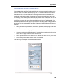
IMAT Online Help can be printed and provides detail instructions on configuring and managing the SX-200 ICP.
1
SX-200 ICP General Information Guide
What’s new?
Release 5.0 UR1
•
The Mailbox Lockout feature enables a user's mailbox to be locked after three unsuccessful login attempts.
•
A new embedded voice mail language, English Overlaid, provides numeric prompts
("Press 7 to play...") in place of the default alphabetic prompts ("Press P to play...").
Release 5.0
•
Support for Mitel 5540 IP Consoles
•
Support for AX controllers
Release 4.0 UR5
•
Support for Mitel 5304 IP Phones
•
Support for Mitel 5312 and 5324 IP Phones
Release 4.0
New Hardware Features
•
New CX controller variation. The original CX controller is now the CXi. The new "switchless" CX is ideal for businesses with existing Layer 2 switches and for those that require
more than 16 ports.
•
CX and CXi controllers now ship with 512 MB internal CompactFlash.
•
New ASU II supports up to 32 ONS phones or up to 8 LS trunks depending on configuration and peripheral cards.
•
Support for Quad CIM modules on new CX/CXi controllers (for ASU II support only—
Bay functionality coming soon.)
•
Support for Mitel 5330 and 5340 IP Phones
•
Support for the Applications Processor Card (APC) — a PC on a compact card installed
in the CX/CXi controller to host the Managed Application Server.
•
Support for Mitel Gigabit Ethernet (GigE) and Wireless LAN (WLAN) Phone Stands
New Software Features
2
•
IP phone capacity for the CX/CXi increased to 100.
•
Number of ARS entries increased to 350.
•
The Ring Groups feature provides the ability to ring all members of a group
simultaneously.
•
The Direct Inward Dialing Server application allows Hotels to automatically assign direct
dial numbers for their guests.
•
New CDE Form 9 subform (Review - Call Forward) provides an onboard Call Forwarding profile editor. (Support for MyAdministrator application has been discontinued.)
About this document
•
Enhanced Hotel/Motel Subattendant features available using the Mitel 5340 IP Phone.
Release 3.1
•
SX-200 ICP MX controller supports up to 238 IP Phones.
•
Headset users can now place calls on Hard Hold while Automatic Line Selection is
selected.
•
Loop Start Trunk Measurement Tool enhancements.
•
Telephones now support Set Page, Group Page, and All Set Page across tie/IP trunks.
•
Single button transfer to voice mail while on Consultation Hold.
•
The 5485 Paging Unit is now accessible to ONS telephones for Paging - PA.
Release 3.0
New Hardware Features
•
Mitel Line Interface Module (LIM): Provides users of 5220 and 5224 Dual Mode IP Phones
with the ability to make and receive calls on an analog line. The LIM replaces the Mitel 5425
Access Module.
•
Support for Application Processor Card (CX)
•
Support for Mitel 5212 and 5224 Dual Mode IP Phones
•
Support for Telematrix 3000IP Phone
Note: Although the 3000IP appears in CDE, it will not be available for programming until
R3.1.
•
SpectraLink NetLink h340 Wireless Telephone
New Software Features
•
The Calling Party Number Substitution feature provides calling party identification for outgoing calls for purposes of network identification and call back.
•
The Direct Inward Dialing Translation feature enables calls received by dial-in trunks to be
routed based on Day, Night1 and Night2 service.
•
Support for Embedded PRI with Dual T1/E1 Framer (MX) or T1/E1 Combo (CX).
•
New options available on Form 42 (Link Descriptor Options): Protocol, Protocol Variant,
Network/User, Unknown Numbering Plan, Bearer capability Voice, CLIR Voice, and Invert
D Channel.
•
New L2 Switch settings (CX): IGMP Snooping; Rapid Spanning Tree; STP Bridge Priority.
•
New System IP settings: DiffServe Code Point; VoiceVLAN ID; Voice VLAN Priority.
•
The CX now supports 802.1 p/Q prioritization for voice traffic on the default VLAN (1), or
on a separate Voice VLAN. Program matching VLAN ID and priority values on Form 47,
Subform 1 (System IP), the DHCP server, and the external L2 switches.
•
Line key enhancements:
-
-Maximum number of line appearances is increased from 32 to 64 for DTS, CO,
3
SX-200 ICP General Information Guide
Logical, Multicall and Key line keys.
-
-Automatic line selection is programmable using either the Line Select or Line
Preference feature.
-
-Call Logging is available for multiple appearances of DTS and CO line keys.
-
-Forward Campon feature is now available if the forwarding destination is a Speed Call
Key or System Abbreviated Dial Number.
-
-Split and Hold features can now be used during conferences with multiple DTS or CO
lines (two or more LS trunks).
-
-If a user on a line appearance of a CO trunk exits a conference initiated by a user with
an ONS set, the conference will continue without interruption.
•
Subattendant functionality extended to Mitel 5020, 5220, 5220 Dual Mode, and 5224 Dual
Mode IP Phones.
•
New Option 16 (IP Set Voice Encryption) available on Form 04 (System Options/System
Timers).
•
DTMF tones can now be transmitted to 5485 IP Pager Unit for PA Paging.
•
6042 Managed VPN now supports Traffic Shaping to ensure QoS for voice calls. With this
feature, smaller sites (fewer than 24 IP Phones) can be interconnected using relatively
low-bandwidth cable or DSL links to the Internet. For more information on interconnecting
sites over IP trunks, Networking Mitel IP-PBXs.
•
Support for additional LS Trunk Line Length and Impedance values in Subform 13 (Trunk
Circuit Descriptors Options). Also see Attenuation Levels for Short and Long CO Trunks.
•
User mailboxes can now start with a 9. To prevent conflict with the Phonebook feature
(Directory Dial by Name), an inter-digit timer is started every time the first digit entered is
9. If no other digits are entered before the timer expires, the user is transferred to the
Phonebook.
•
The time out behavior (disconnect or forward to operator) can now be selected for each
Multi-level Auto Attendant menu node mailbox.
•
Mitel Your Assistant now supports the YA Softphone, an IP-based software phone, and YA
Lite, a free version of the product.
•
The SX-200 ICP now supports disconnect tones for 11 Latin American countries in addition
to the default disconnect tone for Canada/USA. The disconnect tone files are selected via
System Option 138 (Country Variant For Disconnect Tone Control) in Form 04 (System
Options/System Timers).
•
MTCE command to reset the Application Processor Card.
Release 2.3
•
Asian and Latin American tone plan support
Release 2.2
4
•
Line Interface Module support
•
Waiting Lamp indication for queued calls (Mitel Dual Mode 5215 and 5220 IP Phones)
About this document
•
Analog Main Board (AMB) Hardware up-rev to Rev-C (no new functionality added)
•
Echo DSP Filter enhancements
•
IP Paging Unit support enhancement
•
BCC3 logs and robustness support
Release 2.1
•
NetLink e340 and NetLink i640 Wireless Telephones (to replace the discontinued Symbol
MiNET Wireless phones)
•
Stratum 3 Clock Module (CX)
•
support for Category 3 Ethernet cable (CX)
•
Mitel Your Assistant
•
Line Characterization Tool - milliwatt tone loopback
•
Message Flash Notification for Incoming Calls (Mitel 5207 IP Phone)
•
support for SMTP Authentication
•
embedded voice mail now supports notification on every new message regardless of whether or not notification for previous messages has already been answered.
5
SX-200 ICP General Information Guide
6
Overview
Overview
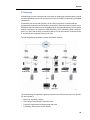
Mitel SX-200 IP Communications Platform
The Mitel SX-200 IP Communications Platform (ICP) delivers superior voice capabilities and
features via a low-cost key telephone system that offers Voice over IP (VoIP), LS/CLASS,
ONS/CLASS and DNIC solutions. Tailored for small enterprises, the Mitel SX-200 ICP offers
the following platforms:
•
SX-200 ICP MX
•
SX-200 ICP CXi
•
SX-200 ICP CX (no internal Layer 2 switch)
•
SX-200 ICP AX
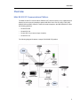
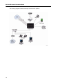
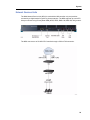
The following diagram illustrates a sample SX-200 MX ICP platform.
7
SX-200 ICP General Information Guide
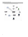
The following diagram illustrates a sample SX-200 CXi ICP platform.
8
Overview
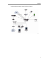
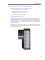
The following diagram illustrates a sample SX-200 CX ICP platform.
9
SX-200 ICP General Information Guide
The following diagram illustrates a sample SX-200 AX ICP platform.
10
System
System
This section describes the SX-200 ICP system architecture and its components.
For more information, refer to:
•
“System architecture” on page 11
•
“SX-200 ICP Controller” on page 12
•
“Network Services Units” on page 23
•
“Analog Services Unit” on page 24
•
“Peripheral Cabinets” on page 26
•
“Peripheral Interface Cards and Modules” on page 27
•
“Desktop Devices” on page 29
•
“Digital Services Cards and Modules” on page 29
•
“Network” on page 32
•
“Directed Data I/O” on page 37
System architecture
The SX-200 ICP is built upon Mitel Data Integrated Voice Applications™ architecture delivering
sophisticated call management, applications and desktop solutions for businesses. Mitel
delivers a highly scalable, resilient, robust call control that fully utilizes the power of IP while
fully supporting the traditional TDM based telephony for legacy devices and PSTN connectivity.
Mitel’s architecture uses the IP network to connect IP telephony devices and provides a
supplementary TDM (Time Division Multiplexing) subsystem to switch calls between traditional
telephone devices. The SX-200 ICP has the advantage of being able to optimally switch all
types of traffic, IP or TDM. The SX-200 ICP provides native call setup, tear down, and signaling
between Ethernet IP connected telephones. For traditional telephony, such as POTS and PSTN
trunks, call handling is also handled natively by the SX-200 ICP via a conventional TDM
circuit-switched subsystem.
This ability to use two different switching techniques simultaneously means that:
•
All traffic is switched with minimum conversion between packet and traditional telephony
to provide optimum voice quality in all call scenarios.
•
Embedded gateway functionality is only required between the IP and non-IP networks
optimizing the use of system resources.
•
Migration from traditional PBX to IP telephony is seamless and efficient.
11
SX-200 ICP General Information Guide
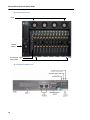
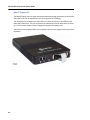
SX-200 ICP Controller
The SX-200 ICP Controller provides voice, signaling, central processing, and communications
resources for the system. There are four controllers available in Release 5.0:
•
CXi Controller
•
CX Controller
•
AX Controller
•
MX Controller
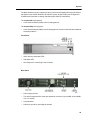
CX/CXi Controllers
CX/CXi controllers have the processing, memory, mass storage, power, and input/output
capabilities to support up to 100 IP phones or 150 ONS/DNIC phones, or a combination of both.
The original CX controller has been renamed as the CXi. The new CX controller, designed
without a Layer 2 switch, is ideal for businesses with existing Layer 2 switches, or for those
that require more than 16 ports.
12
System
Front panel (CXi)
•
RS-232 port (DB-9 connector) for Maintenance terminal
•
10/100Base-TX WAN port
•
10/100/1G LAN interface (CX and CXi)
•
Sixteen 10/100Base-TX 802.3af LAN ports (CXi only)
•
Two USB 1.1 ports for future use
•
Two expansion sites for Dual DSP MMC and T1/E1+DSP+STRATUM 4 Clock MMC
•
CompactFlash card reader
•
Status LEDs
Front panel (CX)
•
RS-232 port (DB-9 connector) Maintenance terminal function (printer function available via
LAN port)
•
10/100Base-TX WAN port
•
10/100/1000Base-TX LAN port
•
Two USB 1.1 ports for future use
•
Expansion sites for Dual DSP and/or T1/E1 Combo modules
•
CompactFlash card reader
•
Status LEDs
13
SX-200 ICP General Information Guide
Rear panel (CX and CXi)
•
Embedded Analog Main Board (AMB) provides 6 LS (RJ11), 4 ONS (RJ11), with 2 PFT
ports, a MOH (3mm) port, a Paging (RJ45) port, 2 generic relays.
•
Embedded Analog Option Board (AOB) provides an additional 6 LS (RJ11), 4 ONS (RJ11),
and 2 PFT ports. (The LS Trunk and ONS ports on the AOB have the same interface
characteristics as the ports on the AMB. The PFT function is associated with ONS1/LS1
and ONS2/LS2 pair.)
•
One AC plug site is provided for the 85-265VAC universal power supply
Internal Components
14
•
Analog Main Board
•
Analog Option Board
•
Hard Drive (Optional)
•
Internal CompactFlash card (512 MB)
•
External CompactFlash card slot
•
250 Watt Power supply
•
Cooling fan
•
Option sites for T1/E1/DSP (also known as T1/E1 Combo) and a dual DSP module
•
Dual DSP module
•
Quad CIM module (for connecting ASUs)
System
AX Controller
The AX Controller provides support for IP devices and analog devices. It is ideal where a high
density of analog devices is required. It can be deployed as a standalone system or included
in a network of systems to provide additional analog support.
The AX Controller supports a maximum of 248 IP devices, or a maximum of 288 ONS devices,
or a combined maximum of 300 devices.
Note: When installed in a low traffic environment (for example, Hospitality), the AX can
support 288 analog sets and 248 IP sets, for a combined total of 536 devices.
The AX Controller provides
•
12 line card slots to support analog phones and trunks. The following cards are available:
-
24-port ONS line card
-
4 + 12 port combo card (4 analog trunks and 12 ONS ports)
•
two 10/100 BaseT Ethernet LAN ports (RJ-45 connector).
•
one externally accessible expansion slot and one internal expansion slot for up to two of
the following optional modules:
•
-
Dual T1/E1 (external)
-
T1/E1 Combo (external)
-
DSP (internal or external).
4 GByte flash card (hosts system files, partitions, and voice mail storage)
Optionally, you can install:
•
second AC Power Supply Unit (PSU) for power redundancy
•
line cards.
The AX Controller consists of a card chassis, power supply, controller card, and the optional
line cards. The power supply, controller card, and line cards are accessed from the rear of the
controller.
15
SX-200 ICP General Information Guide
AX Controller Rear View
FANS
POWER
SUPPLY
AX CONTROL CARD
LINE CARDS
AX Controller Controller Card
16
System
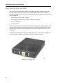
MX Controller
The MX Controller has the processing, memory, mass storage, power, and input/output
capabilities to support up to 248 IP phones or 650 ONS/DNIC phones or a combination of both.
It provides 64 channels of Ethernet to Time Division Multiplexing (E2T) and 64 channels of
echo cancellation.
The MX Controller is shipped with a Dual DSP Module and embedded Dual CIM for baseline
telephony requirements and can be configured with:
•
An additional DSP for G.729 compression (or voice mail ports depending on business
configuration that is ordered)
•
A Dual FIM for connecting NSUs or Peripheral Cabinets
•
One or two Quad CIMs for connecting NSUs or Peripheral Cabinets
•
One or two Dual T1/E1 Framers
These modules are shipped separately and must be installed on site.
The MX Controller can ship with embedded analog capability provided by one or two optional
analog boards:
•
Analog Main Board (AMB) provides 2 DNIC ports, 6 Loop CLASS, 2 ONS, 1 Music On
Hold, and 1 Paging circuit
•
Analog Option Board (AOB) expands on the AMB providing an additional 6 LS CLASS and
2 ONS circuits
17
SX-200 ICP General Information Guide
Front panel
Rear panel
•
Power connector
•
Protective ground to ground the chassis
•
Music on Hold connector
•
Paging/Door Sense Contacts connector
•
Amphenol Connector for analog trunks and ONS/DNIC stations
Internal components
18
•
Analog Main Board
•
Analog Option Board
•
Hard Drive (Optional)
•
Internal CompactFlash card
•
External CompactFlash card slot
•
Stratum Clock (Optional)
•
Dual DSP Module/Quad DSP Module (Optional)
•
Dual FIM Module (Optional)
System
•
Quad CIM (Optional)
•
Power supply
•
Cooling fan
•
System ID Module
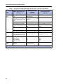
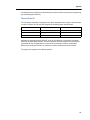
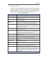
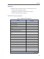
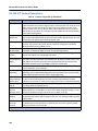
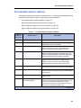
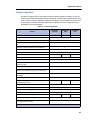
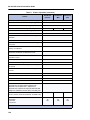
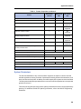
Comparison of SX-200 ICP MX, CX/CXi, and AX controllers
The SX-200 ICP MX, CX/CXi, and AX controllers share the same call control software; however,
there are key differences between their hardware.The SX-200 ICP CXi controllers have a Layer
2 switch (managed and powered) built in; the MX, CX, and AX do not. The maximum number
of IP desktops for the SX-200 ICP MX is 248; for the SX-200 ICP CX/CXi it is 100, and for the
AX it is 248. The MX provides more TDM expansion room than the CX/CXi controller.
For specific details on the differences between these controllers, refer to the following table.
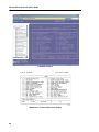
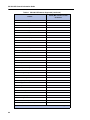
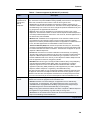
Table 1: Comparison of SX-200 ICP MX, CX/CXi and AX controllers
Area
Base system
SX-200 ICP CX/CXi
controller
(100 user)
SX-200 ICP MX controller
(200 user)
SX-200 AX Controller
(200 user)
1 LAN port
1 WAN port
1 10/100/1 GigE LAN port
16 10/100 802.3af LAN ports
(CXi only)
2 10/100 LAN ports
Internal hard drive
512 MB internal Compact
Flash
4GB internal Compact Flash
3 MMC slots
2 MMC slots
2 MMC slots
Dual DSP MMC (max 8 DSPs) Dual DSP on mainboard (max
7 DSPs)
Dual and Quad DSPs (max 8
DSPs)
3 serial ports (maintenance,
printer, alarms)
1 serial port for maintenance
1 serial port for Maintenance
Terminal
SYSID module for MOSS
System i-Button for MOSS
System i-Button for MOSS
Analog mainboard with 2
ONS/2DNIC/6 LS (RJ77),
music, pager and night bell
Analog mainboard with 4
ONS/6LS (RJ11), music,
pager and night bell/door
sensor/alarm
n/a
Stratum 3 clock
n/a
n/a
Echo cancellation in hardware
Echo cancellation in software
on dual DSP mainboard
Echo cancellation in software
on dual DSP mainboard
Page 1 of 4
19
SX-200 ICP General Information Guide
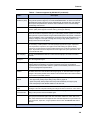
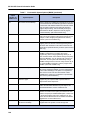
Table 1: Comparison of SX-200 ICP MX, CX/CXi and AX controllers (continued)
Area
Field
Replaceable
units
SX-200 ICP CX/CXi
controller
(100 user)
SX-200 ICP MX controller
(200 user)
Line and
Trunk
Interfaces
Supported
(200 user)
Dual and Quad DSP MCC
Dual and Quad DSP MMC
Dual and Quad DSP MMC
Dual T1/E1 Framer card
T1 Combo card (T1 link; DSP;
Stratum 4 clock)
Dual T1/E1 Framer card
T1 Combo card (T1 link; DSP;
Stratum 4 clock)
Internal hard drive
Internal hard drive (optional)
N/A
Optional Analog board with 2
ONS/6LS
Optional analog board with 4
ONS/6LS
N/A
Stratum 3 clock
Stratum 3 clock
Stratum 4 clock on T1 Combo
card
Stratum 4 clock on T1 Combo
card
Nodes
supported
SX-200 AX Controller
Dual FIM MMC (optional)
N/A
N/A
Quad CIM MMC (optional)
Quad CIM MMC (optional)
N/A
Digital (TDM) Bays
N/A
N/A
NSU (PRI only)
N/A
N/A
ASU (24 ONS only)
N/A
N/A
ASU II (16 ONS, 24 ONSp, or
12 ONS/ 4 LS combo)
ASU II (16 ONS, 24 ONSp, or
12 ONS + 4 LS combo)
N/A
ONS/CLASS
ONS/CLASS
ONS/CLASS
OPS
N/A
N/A
DNIC
N/A
N/A
IP
IP
IP
LS/GS
N/A
N/A
LS/CLASS
LS/CLASS
LS/CLASS
DID (Analog)
N/A
N/A
E&M (Analog)
N/A
N/A
T1/D4 (embedded module in
controller or card in peripheral
cabinet)
T1/D4 (embedded module)
T1/D4
PRI (embedded module in
controller, card in peripheral
cabinet, or NSU)
PRI (embedded module in
controller)
PRI
IP Trunk
IP Trunk
IP Trunk
Page 2 of 4
20
System
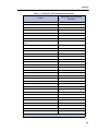
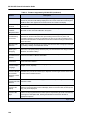
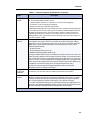
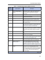
Table 1: Comparison of SX-200 ICP MX, CX/CXi and AX controllers (continued)
Area
Feature
Packages
supported
Applications
supported
SX-200 ICP CX/CXi
controller
(100 user)
SX-200 ICP MX controller
(200 user)
SX-200 AX Controller
(200 user)
ACD
ACD (on IP sets only)
ACD (on IP sets only)
Hospitality
Hospitality
Hospitality
Tenanting
Tenanting
Tenanting
Centralized Voice mail
Tenantingl
Tenanting
Automated Attendant and Fax
Tone Detect
Automated Attendant and Fax
Tone Detect
Automated Attendant and Fax
Tone Detect
Mitel Express Messenger™
(version 4.11 and later
supported on migration only)
N/A
N/A
SMTP Client
SMTP Client
SMTP Client
MiTAI™ (version 11.2 and
later)
MiTAI (version 11.2 and later) MiTAI (version 11.2 and later)
N/A
Internet Gateway (CXi only)
N/A
24 Voice Mail ports
16 Voice Mail ports
20 Voice Mail ports
Teleworker Solution (version
3.0 and later)
Teleworker Solution (version
3.0 and later)
Teleworker Solution (version
3.0 and later)
Mitel Contact Center (6110)
(version 4.5 and later)
Mitel Contact Center (6110)
(version 4.5 and later)
Mitel Contact Center (6110)
(version 4.5 and later)
Mitel Contact Center
Scheduling (6120) (version 4.5
and later)
Mitel Contact Center
Scheduling (6120) (version
4.5 and later)
Mitel Contact Center
Scheduling (6120) (version
4.5 and later)
Mitel Real-Time Schedule
Adherence (5125)
Mitel Contact Center
Scheduling (6120) (version
4.5 and later)
Mitel Contact Center
Scheduling (6120) (version
4.5 and later)
Mitel Multimedia Contact
Center (6150)
MItel Multimedia Contact
Center (6150)
MItel Multimedia Contact
Center (6150)
Mitel Intelligent Queue (version N/A
2.4, Analogue connection only)
N/A
Mitel Speech Server (6500)
(version 4.6, DNIC connection
only)
N/A
N/A
Unified Messaging - Standard
Unified Messaging - Standard
Unified Messaging - Standard
(Managed Application
Server-based)
(Managed Application
Server-based)
(Managed Application
Server-based)
MiTAI SDK
MiTAI SDK
MiTAI SDK
Mitel Your Assistant
Mitel Your Assistant
Mitel Your Assistant
NuPoint Messenger™
(Version 8.5 and later)
N/A
N/A
Page 3 of 4
21
SX-200 ICP General Information Guide
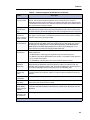
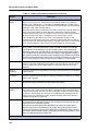
Table 1: Comparison of SX-200 ICP MX, CX/CXi and AX controllers (continued)
Area
Operations
and
Maintenance
SX-200 ICP CX/CXi
controller
(100 user)
SX-200 ICP MX controller
(200 user)
SX-200 AX Controller
(200 user)
Software on internal flash/hard
drive
Software on internal
flash/hard drive
Software on internal flash
Hot-swappable external
compact flash (release 2.0 and
later)
(embedded module in
controller)
4GB Flash Card
InstallShield for
software/database installation
InstallShield for
InstallShield for
software/database installation software/database installation
New install and upgrade with
flash
New install and upgrade with
flash
New install and upgrade with
flash
Remote upgrade via FTP
server
Remote upgrade via FTP
server
Remote upgrade via FTP
serve
Default and blank databases
Default and blank databases
Default and blank databases
Call control
Platform independent with
additional functionality through
bays and support of older sets
Platform independent; does
not support older sets
Platform independent; does
not support older sets
Voice mail
EMEM
EMEM
EMEM
ONS Voicemail
N/A
N/A
DNIC Voicemail
N/A
N/A
MEM (card in bays)
N/A
N/A
Embedded Layer 2 switch not
supported
Embedded Firewall, Internet
Gateway (CXi only)
Layer 2 switch is supported
Layer 2
switch
Page 4 of 4
22
System
Network Services Units
The Mitel Network Service Unit (NSU) is used with the MX controller only and provides
connectivity to digital trunks for public or private networks. The NSU supports up to two PRI
links per unit both using Primary Rate ISDN (4ESS, 5ESS, DMS 100, DMS 250, NI2) protocol.
The NSU connects to an SX-200 ICP Controller through a CIM or FIM connection.
23
SX-200 ICP General Information Guide
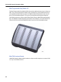
Analog Services Unit
The Analog Services (ASU) unit is used with the MX controller only and provides 24
ONS/CLASS circuits. Up to six ASUs can be connected to an MX Controller. Connection is via
a Category 5 Universal Twisted Pair (UTP) cross-over cable through a CIM interface.
Note: The ASU only supports DTMF telephones (pulse or rotary dial phones are not supported).
Front Panel
•
24 ONS Circuit LEDs indicate the status of the telephone circuits
•
1 CIM circuit LED indicates the status of the CIM link
•
RJ-45 connector (CIM connection to the Controller)
Back Panel
•
25 pair D-type connector provides access to the ONS Tip/Ring circuits.
•
Standard Male IEC AC input connector for power requirement.
Analog Services Unit II
The ASU II is used with both MX and CX/CXi controllers and supports up to 48 ONS phones
or up to 8 LS trunks depending on how the unit is configured with peripheral cards:
The 4 + 12 port combo card supports:
24
•
12 On-Premise Station (ONS) Lines for analog phones
•
Four Loop Start (LS) trunks for analog connection to a central office
•
Four System Fail Transfer (SFT) relays that provide direct connection between an analog
telephone and a Loop Start trunk in the event of system or power failure.
System
The North American version supports Custom Local Access Signalling Services (CLASS) on
the ONS circuits. CLASS allows the SX-200 ICP system to pass Calling Line ID digits and
CLASS name information to display sets that support Caller ID functionality.
The 16 port ONS card supports:
•
16 On-Premise Station (ONS) Lines for analog phones
The 24 port ONSp card supports:
•
24 On-Premise Station (ONS) Lines for analog phones. Circuits on this card have additional
electrical protection.
Front Panel
•
Alarm, activity, and power LEDs
•
CIM status LED
•
One CIM port for connecting to the Controller
Back Panel
•
Power supply and fan
•
Two slots for peripheral line cards with amphenol connector (16 port ONS, 24 port ONSp,
or 4+ 12 Combo)
•
Card identifiers
•
Protective ground for grounding the chassis
25
SX-200 ICP General Information Guide
Peripheral Cabinets
SX-200 Peripheral Cabinets are supported on the SX-200 ICP MX only. Up to seven cabinets
can be connected to the controller via a combination of seven CIM and/or four FIM cables. The
cabinets can be SX-200 ELx peripheral cabinets, SX-200 LIGHT peripheral cabinets, or a mix
of both.
SX-200 ELx Cabinet
The SX-200 ELx peripheral cabinet is horizontal and can be mounted in a standard 19" rack,
or they can be stacked. The cabinet is plastic and Plexiglas. The door on the cabinet allows
the system administrator to see the system status at a glance. The control cabinet and the
peripheral bays are linked by fibre or copper cables.
The SX-200 ELx cabinet supports 12 card slots: eight slots support line and trunk cards, and
four support the control cards and the FIM or CIM carrier cards.
SX-200 LIGHT Peripheral Cabinet
The SX-200 LIGHT Peripheral Cabinet is vertical. The cabinet contains one Bay Power Supply,
one Bay Control Card (with attached Peripheral FIM Carrier plus FIM), and up to eight peripheral
interface cards.
Peripheral Bay Power Supplies
The Bay Power Supply (BPS) is card-mounted and is located in the Peripheral cabinet. The
BPS connects to the backplane through a card-edge connector at the rear of the card. Also at
the rear is an IEC receptacle which connects to a line cord from the system ac distribution. The
input to the converter is protected by a fuse, and by low voltage protection which shuts off the
converter if the input voltage falls below the specified minimum. The converter has a single
alarm signal, PFS (power fail sense), which is driven low when the incoming ac falls below its
minimum specified value.
26
System
Peripheral Interface Cards and Modules
The following cards are installed in the SX-200 ICP peripheral cabinets:
•
“Universal Card” on page 27
•
“ONS/CLASS Line Card” on page 27
•
“Digital Line Card” on page 27
•
“LS/GS Trunk Card” on page 28
•
“LS/CLASS Trunk Card” on page 28
•
“Direct Inward Dial (DID) Trunk Card” on page 28
•
“Off-Premise (OPS) Line Card” on page 28
•
“Mitel Express Messenger Card” on page 28
•
“Peripheral FIM Carrier” on page 28
•
“Peripheral FIM Carrier II” on page 28
Universal Card
The Universal Card is a high power card that holds up to four modules. Each module is assigned
a power rating. The cumulative ratings of the modules on the Universal Card cannot exceed a
value of 10. The modules are as follows:
•
Receiver/Relay Module (contains four DTMF receivers and two relays) (power rating = 2)
•
Music-on-Hold/Pager Module (contains one music input, one PA paging output) (power
rating = 1)
•
E&M Trunk Module (contains one E&M trunk) (power rating = 3)
ONS/CLASS Line Card
The ONS/CLASS Line card is a low power card and replaces the ONS Line card. The card has
the same functionality as the ONS Line card and if software enabled, offers CLASS functionality.
The ONS/CLASS Line card has 12 DTMF/Rotary line circuits per card. The card accepts up to
three industry-standard DTMF/Rotary telephone sets per line circuit. The card interfaces the
telephone analog input with the system’s digital crosspoint network. It converts the analog
telephone signals into the digital format used by the system, and converts the digital information
back into the analog signals required by the telephone sets.
Digital Line Card
The Digital Line Card (DLC) is a low power card with 12 Digital Network Interface Circuits (DNIC)
per card. The Digital Line Card interfaces DNIC-based peripheral devices to the system through
its Digital Network Interface Circuits (DNIC); the DNIC is a proprietary integrated circuit. DNIC
devices include Mitel Superset™ 4001, Mitel Superset 4015, Mitel Superset 4025, Mitel
Superset 4125, Mitel Superset 4150, Mitel Superset 401+, Mitel Superset 410, Mitel
Superset 420, Mitel Superset 430 telephones, Mitel Programmable Key Modules (PKM),
DATASETs, SUPERCONSOLE 1000® Attendant Console, DMP Module.
27
SX-200 ICP General Information Guide
LS/GS Trunk Card
The LS/GS Trunk card is a low power card that contains six loop start or ground start trunks
(jumper-selectable) and six message registration inputs. The card may be installed in any digital
peripheral slot. Facilities provided by the LS/GS Trunk Card include: Loop Start or Ground Start
selectable by jumper, M and MM signaling leads (refer to the feature, Meter Pulse Collection),
trunk activity indicated by LED (one per trunk), transient suppression on Tip, Ring, and signaling
leads, and an alarm LED.
LS/CLASS Trunk Card
The LS/CLASS Trunk card interfaces eight trunk circuits to the system. LS is the acronym for
Loop Start and CLASS is the acronym for Custom Local Area Signaling Services (allows the
system to receive calling Line ID digits and CLASS name on incoming CLASS trunks). The
LS/CLASS Trunk card can be installed into slots one to eight in a SX-200 rack mount cabinet.
The LS/CLASS Trunk card provides loop start operation, forward/reverse current detectors
(polarity reversal, answer supervision), alarms and trunk activity indicated by an LED (a single
LED for any circuit in use), CLASS signal reception, and transient suppression on Tip and Ring
leads.
Direct Inward Dial (DID) Trunk Card
The DID trunk card is a high power card that contains six 1-way Direct Inward Dial circuits. The
DID trunk allows incoming trunk calls to dial directly to an extension within the system without
attendant intervention.
Off-Premise (OPS) Line Card
The OPS line card is a low power card that interfaces the system to analog extensions which
are part of the system, but are located in a different building from the PBX. It contains additional
protection circuitry to protect the system from extraneous high voltages or induced currents
that may appear on the line. Each OPS card has six circuits.
Mitel Express Messenger Card
The Mitel Express Messenger card is a low-power card. The card uses a DNIC interface that
connects directly to the backplane of the cabinet. The card provides either two, four, six, or
eight voice mail ports.
Peripheral FIM Carrier
The Peripheral FIM Carrier (PFC) provides the interface between the Bay Control Card and
the Fiber Interface Module for the SX-200 LIGHT Peripheral cabinet. It connects to the module
position on the Bay Control Card and acts as a carrier for the Fiber Interface Module.
Peripheral FIM Carrier II
The Peripheral FIM Carrier II (PFC II) provides the interface between the backplane of an
SX-200 RM peripheral cabinet and its Fiber Interface Module.
28
System
Manufacture discontinued or unsupported devices
The following devices have been manufacture discontinued by Mitel. However, they are
supported on SX-200 ICP MX controller systems that have been upgraded from the
SX-200 EL/ML.
•
Superset 3DN and Superset 4DN telephones
•
Superset 400 series telephones
•
Superset PKM
•
MiLINK® Data Module
•
LCD Console
•
SUPERCONSOLE 1000
•
DSS/BLF Interface Unit
The following devices are not supported on the SX-200 ICP system:
•
Superset 3 and Superset 4 telephones
•
Superset 4 telephones for voice mail
•
Modem Interconnect Panel
•
DATASET 1102 Rack-mounted Dataset
•
DATASET 2102 Rack-mounted Dataset
•
DATACABINET 9000 data cabinet
•
DATASHELF 9100 datashelf
•
ISDN Gateway
•
MyAdministrator software application
Desktop Devices
For details on each of these devices supported on SX-200 ICP, refer to “Desktop Devices” on
page 39.
Digital Services Cards and Modules
The following Digital Services cards and modules are supported on the SX-200 ICP:
•
“T1 Trunk Card” on page 30
•
“Bay Control Cards” on page 30
•
“PRI Card” on page 30
•
“Fiber Interface Modules (FIM and FIM II)” on page 30
•
“Dual Fiber Interface Module” on page 31
29
SX-200 ICP General Information Guide
•
“Peripheral Interface Module Carrier Card” on page 31
•
“T1/E1 Module” on page 31
•
“Dual Link T1/E1 Framer MMC” on page 31
•
“T1/E1 Combo MMC” on page 31
•
“CIM (Copper Interface Module)” on page 31
•
“Quad Copper Interface Module” on page 32
•
“DSP Modules” on page 32
T1 Trunk Card
The T1 Trunk Card is a high power card that provides an interface to one 24-channel (D4 format)
T1 link. In an SX-200 rack mount cabinet, T1 trunk cards plug into slots 10 and 11 (slots 5 and
6 respectively must then be left vacant). Because of signal cable restrictions in an SX-200 FD
cabinet, the T1 card must be positioned in slot 6. With a dual T1 adapter, two T1 trunk cards
(in slots 5 and 6) are allowed.
Bay Control Cards
The bay control cards provide control of operations within the cabinet and monitor the lines,
trunks and other circuits within the bay. Reports are sent to the 200 ICP Controller via HDLC
message links. One bay control card is required in each cabinet.
The bay control cards are BCC II and BCC III. The BCC III supports a DSP module (single), a
T1/E1 module, and a FIM II or CIM. The T1/E1 module and the FIM II provide a cost-effective
solution for T1 network connectivity for a remote system. The CIM offers extra savings for a
co-located system. The DSP module supports the ONS/CLASS Line card and the Record a
Call feature. The BCC III cannot be installed in a LIGHT Peripheral Cabinet.
PRI Card
The PRI card provides Primary Rate Access (PRA) to the ISDN service provider. The PRI card,
preloaded with software, comes with a T1/E1 module that supports up to two T1 links of ISDN
connectivity. The PRI card also requires a Stratum 3 clock in the SX-200 ICP controller. The
PRI card (unlike the T1 card) is not classed as a high power card. Because the PRI card is a
separate bay, the PRI card is not included in the count for the four high power cards. The PRI
card cannot be installed in a LIGHT Peripheral Cabinet.
Fiber Interface Modules (FIM and FIM II)
There are two main types of Fiber Interface Modules: FIM and FIM II. The FIM and FIM II
provide a fiber optic based communications link between the SX-200 ICP and a peripheral
cabinet or NSU that houses an equivalent FIM. The main difference between the FIM and FIM
II is where they are installed. The Fiber Interface Module (FIM) sits on Control FIM Carrier cards
and Peripheral FIM Carrier II cards. The FIM II is a module that resides on a PRI card, on a
Bay Control Card III (BCC III), or on a Peripheral Interface Module Carrier card. The FIM II on
a PRI card is an alternative to the FIM on a control carrier card. The FIM II on the BCC III (in
a peripheral cabinet only), is an alternative to the FIM on the Peripheral FIM Carrier II card.
30
System
The FIM II on a Peripheral Interface Module Carrier card provides connectivity when the
peripheral cabinet does not have a BCC III to hold a FIM II. The FIM II module does not apply
to LIGHT Peripheral Cabinets.
Dual Fiber Interface Module
The Dual FIM module, available on the MX controller only, is an optional electrical/optical
interface. It connects SX-200 Peripheral Cabinets or NSUs to the controller through fibre optic
cable. When transmitting, the module converts electrical signals to optical signals for output
over a fiber optic cable. When receiving, it converts optical signals from the cable to electrical
signals. The MX can support up to two Dual FIMs installed in MMC slots 1 and 2. The Dual FIM
is available as a Field Replaceable Unit (FRU).
Peripheral Interface Module Carrier Card
The Peripheral Interface Module Carrier card is a carrier card for a FIM II or a CIM. The card
provides fiber or copper connectivity between a peripheral cabinet and a main control cabinet
when the peripheral cabinet has a BCC II instead of a BCC III. Instead of using the Peripheral
Interface MMC, if the BCC III was in the peripheral cabinet, the interface modules (FIM II or
CIM) on the BCC III would provide the connectivity needed to the main control cabinet.
T1/E1 Module
The T1/E1 module on site 2 of the PRI card provides up to two links of ISDN connectivity. The
T1/E1 module on site 2 of the BCC III provides up to two T1 links. The links from the module
provide CSU and ESF functionality.
Dual Link T1/E1 Framer MMC
The Dual T1/E1 Framer MMC is available as option for the MX and AX controller. The module
has two digital trunk ports, each of which can be configured as a T1 interface (1.544 Mbits/sec)
that provides 24 B-channels for T1/D4. The Dual T1/E1 Framer also supports PRI. Up to two
modules can be installed in MMC slots 1 and 2. The Dual T1/E1 Framer is available as Field
Replaceable Unit (FRU).
T1/E1 Combo MMC
The T1/E1 Combo MMC combines trunking and DSP functionality in a single card for the CX/CXi
and AX controllers. The digital trunk port can be configured as a T1 (1.544 Mbits/sec) that
provides 24 B-channels for T1/D4. The T1/E1 Combo also supports PRI. The DSP provides
resources for CLASS tone generation, Record a Call conferences, DMTF receivers, voice
compression, and voice echo cancellation. The module also includes a Stratum 4 clock. The
CX/CXi can support a single T1/E1 Combo MMC installed in MMC slot 1 or 2. The AX can
support a single T1/E1 Combo MMC installed in MMC slot 1 only. The module is an optional
Field Replaceable Unit (FRU).
CIM (Copper Interface Module)
The CIM provides copper connectivity between the peripheral cabinets and the controller. The
CIM is very cost effective for a system that is co-located. The CIM supports a distance of up to
31
SX-200 ICP General Information Guide
30 meters or 100 feet between cabinets. The CIM sits on a Peripheral Interface Module Carrier
card in a peripheral cabinet, on site 1 of the BCC III in a peripheral cabinet, or on site 1 of a
PRI card in a peripheral cabinet. Unlike the FIM II, the CIM sits close to the faceplate and only
has one variant.
The MX controller is equipped with an onboard dual-port Copper Interface Module (CIM). An
optional Quad CIM module provides four more ports. Up to two Quad CIMs can be installed in
MMC sites 1 and 2.
Quad Copper Interface Module
The MX controller is equipped with an onboard dual-port Copper Interface Module (CIM). An
optional Quad CIM module (available for both the MX and the CX/CXi) provides four more
ports. Up to two Quad CIMs can be installed in MMC sites 1 and 2. CIM ports can be connected
to ASUs, ASU IIs, NSUs, or Peripheral Cabinets. Although a single-port CIM is available for
use in the SX-200 Peripheral cabinet, this module cannot be installed in an SX-200 ICP.
DSP Modules
DSP (Digital Signal Processor) modules are available in three configurations: Single, Dual, and
Quad. The Single DSP services an SX-200 Peripheral Cabinet and sits on Site 3 of the Bay
Control Card III (BCC III). The Dual and Quad reside in the SX-200 ICP controller. The Single
DSP module provides the following functionality:
•
CLASS tones for the ONS/CLASS Line card. This DSP module has 8 CLASS generator
resources that are assigned and released dynamically as they are required. The DSP
module on the BCC III must reside in the same bay as the ONS/CLASS Line card.
•
Sixteen conference bridges for the Record-a-Call feature. The DSP module provides these
bridges to circuits in the same bay. A Record a Call conference is between one internal
party, one external party (a trunk call) and the voice mailbox. A Record a Call conference
can also be setup between two internal parties and the voice mailbox.
•
Sixteen DTMF receivers that can be used system wide. The DSP module replaces the
Universal Card with respect to DTMF receivers.
The Dual and Quad DSPs provide the functionality of the Single DSP but in greater quantities
plus voice compression resources.
Application Processor Card (CX/CXi only)
The Application Processor Card is a PC on a compact card. Installed in the CX/CXi controller,
the Application Processor Card hosts the Managed Application Server (MAS) and associated
applications. The Application Processor Card requires a dedicated hard drive.
Network
32
•
“ISDN (Integrated Services Digital Network)” on page 33
•
“IP Networking” on page 35
•
“Ethernet WAN and LAN interfaces” on page 36
System
•
“Internet Gateway (CXi only)” on page 36
•
“Embedded firewall (CXi only)” on page 36
ISDN (Integrated Services Digital Network)
ISDN support is provided from the ISDN Primary Rate Interface Card (PRI) card in the peripheral
cabinet, from the NSU, or on the embedded T1/E1 modules. For more information on the NSU,
refer to “Network Services Units” on page 23. For a list of ISDN network services supported by
the PRI card and the NSU, refer to “Supported ISDN network services” on page 33.
The Integrated Services Digital Network (ISDN), transmitting voice, data and video at high
speeds, accurately and without a modem, has revolutionized communications. ISDN services
can be deployed and accessed at enterprise, department and desktop levels by its simple
addition to your existing SX-200 network. ISDN proves its worth by its ability to carry voice,
data and video imaging on one network.
The SX-200 ICP MX supports Primary Rate Interface (PRI) via the NSU or a PRI card in a bay,
or on the embedded T1/E1 module.
ISDN Primary Rate Interface Card
ISDN PRI is becoming the most cost-effective solution for accessing enhanced voice
capabilities. All inbound and outbound services that are usually obtained by using different trunk
types (such as INWATS, OUTWATS, FX, Tie, and DID) can be accessed with a single ISDN
trunk; as a result, the number of system trunks can be reduced by 10 to 15 percent. On outbound
calls, the system requests the required service from the Network. The trunk takes on the
requested characteristics for the duration of the call.
The PRI card in the peripheral cabinet and the NSU cabinet provides two ISDN links and has
the Bearer Capabilities (BC) of Speech (voice) and 3.1 kHz audio. The card also transports the
BCs of rate-adapted 56 kbs data and unrestricted 64 kbs data transparently through the system.
Supported ISDN network services
•
Calling Party Number (CPN) - This number substitutes the calling station number on
outgoing calls for purposes of network identification and call back.
•
Calling Name ID (CNID) - This ID is the incoming calling name delivery per NA DMS100
custom specification or National ISDN-3 (NI3).
•
Calling Line Identification Presentation (CLIP) - The Calling Party Number can be provided to the ISDN Network for outgoing calls or provided to the PRI card from the ISDN
Network for incoming calls. This information is passed onto the system and can be used
for database applications such as screen pops and for inclusion in SMDR records.
•
Calling Line Identification Restriction (CLIR) - This feature allows users to prevent their
telephone number from being presented to the called party.
•
Partial PRI Links - The SX-200 PRI card will support COs that provide this feature.
•
Direct Dial-In (DDI) - DDI is an ISDN option that allows direct access to a line behind a
system through a unique directory number. This allows the dialed digits of an incoming
33
SX-200 ICP General Information Guide
ISDN call to be presented to the system. All ISDN trunks are treated as Dial-In trunks; the
CO always sends digits to the system.
34
•
Call-By-Call Service Selection (CBC) - This feature allows telephone users to select the
ISDN network services that they wish to use on a per call basis.
•
DID Calling Party Number Forwarding - Outgoing CPN delivers the calling party’s DID
number to the Network when the call has been identified as a call from a device with an
associated DID number instead of delivering the main directory number associated with
the system.
•
Equal Access to Interexchange Carriers - The system provides a carrier access code
which identifies to the Central Office which Interexchange Carrier is to receive the call. The
system outpulses a digit string which includes a carrier access code, followed by an identification number, followed by the called number.
•
Min/Max (PRI card and NSU only) - This feature allows a customer to control incoming
and outgoing call traffic. Minimums are assigned to ensure that a particular type of call
(such as INWATS) always has a set number of lines available. Maximums are assigned to
limit certain types of calls, i.e., OUTWATS. This ensures that resources are not used up by
a single type of call. Different Min/Max databases can be created for different times of the
day or for special occasions such as telethons or infomercials.
•
Auto Min/Max (PRI card and NSU only) - This feature provides user programmable
time-of-day automatic control of Min/Max parameters.
•
NFAS (Non-Facility Associated signaling) (PRI card and NSU only) - NFAS allows you to
use a single D-channel to handle the signaling requirements for a group of PRI links that
all use the same Protocol. This feature eliminates the need to purchase a D-channel for
each link. NFAS is mainly for North America.
•
D-Channel Backup (PRI card and NSU only) - This feature is used for signaling to establish
and maintain the circuit, and to send user data. D-channel Backup provides an alternate
D-channel for calls related to NFAS. If the active D-channel fails, the system switches to
the backup D-channel to support call processing. This functionality is mainly for North
America. NFAS is required in order to program D-channel Backup.
•
Q.SIG (PRI card and NSU only) - This feature provides the ability to connect Q.SIG compatible PBXs from different vendors together to form a private network and to connect the
SX-200 ICP to the SX-2000® LIGHT system or any other Q.SIG compatible PBX. Q.SIG
features that are supported include Calling Name for incoming calls, Message Waiting
Indication, Call Transfer, Call Diversion, and Path Replacement.
•
Remote LAN Access - This feature provides LAN access to the wide area network (WAN)
for both incoming and outgoing calls through LAN servers (routers or bridges).
•
Multiple Variants and Configurations - This feature provides the ability to run multiple
protocol variants and program multiple configurations on the two links of the PRI Gateway
through the IMAT application. The option to run multiple variants allows you to connect the
PRI Gateway to two different CO switches. The option to run multiple configurations allows
you to program Network-side on one link of the PRI Gateway and program User-side on
the other link of the PRI Gateway. For more information on programming multiple variants
and configurations, refer to the IMAT online Help.
System
IP Networking
IP Networking provides customers with a new option for networking systems together. Instead
of leasing dedicated voice circuits, customers can route voice traffic over the existing LAN/WAN
infrastructure.
IP Networking for the SX-200 ICP (MX, CXi, and AX) is supported. Controllers that are
geographically separated can be seamlessly networked to share information and services in a
transparent and cost efficient manner. IP Networking can be used as the primary communication
between controllers or as a backup to TDM networking. The IP Networking feature supports
both G.711 and G.729 encoding. Connections with up to 100 other network nodes and a total
of 24 channels are supported from any one node.
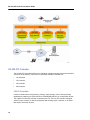
The following diagram illustrates a sample SX-200 ICP network.
The IP Networking call signaling supported is based on the Q.SIG feature set of the SX-200
ICP and consists of:
•
Basic Call: incoming, outgoing
•
Call Failures: Busy, Reorder, Alternative route
•
Transfers: Supervised and Unsupervised with recall
•
Forwarding: Always, Busy and No Answer
35
SX-200 ICP General Information Guide
•
Call Offer: Camp on
•
Networked Voice mail
•
Networked Attendant
•
Message Waiting Indicators
•
Network Voice mail Softkeys
Ethernet WAN and LAN interfaces
In addition to standard telephony interfaces, the SX-200 ICP CXi includes a complete range of
Ethernet interfaces. It has a WAN interface for connection to the Internet at 10 or 100 Megabits
per second. The WAN interface can obtain an IP address by DHCP or PPPoE, or be
programmed with a static IP address and default gateway.
Note: IP Trunking is not supported over the CXi WAN interface. All IP Trunks must be
via the LAN interfaces (AX, CXi and MX).
The 200 ICP CXi also has a 16-port, 10/100 Layer 2 switch for connection to an Ethernet LAN.
Each of the 16 ports provides power to IP devices in compliance with the ’Power over Ethernet’
specifications in IEEE 802.3af.
The 200 ICP AX has a two-port, 10/100 Layer 2 switch for connection to an Ethernet LAN.
The CXi also has an unpowered 1 Gigabit Ethernet port for connection to another switch on
the LAN. By connecting another switch, it is possible to increase the connection capacity for
the CXi from 16 to 100, with 16 connected to the onboard switch and 84 connected to the
offboard switch(es).
The internal switch uses a traffic prioritization scheme based on IEEE 802.1 p/Q VLAN
prioritization standards. This ensures the quality of voice calls by routing packets with priority
value 6 (from IP phones) ahead of packets with priority value 0 (from PCs and other IP devices).
Internet Gateway (CXi only)
The primary function of the Internet Gateway is to link the internal and external networks. In
this role, it performs many-to-one NAT (Network Address Translation), converting private IP
addresses on the LAN to a single public IP address on the WAN interface. NAT redirect, or "IP
port forwarding," is included as a programmable feature, enabling external traffic to reach
internal services or machines. The Internet Gateway also provides firewall functionality, logging
unknown packets and then either dropping or rejecting them, or allowing the packets to pass
through to the internal network. If VPN tunnels are in use, the Internet Gateway can perform
IPSec and PPTP pass-through, and can function as a PPTP server.
Embedded firewall (CXi only)
The firewall examines all packets destined for the internal network. Unless they are addressed
to a specific TCP or UDP port programmed on the firewall, the packets are declared "unknown"
and then either dropped or rejected. Unknown packets are also logged.
36
System
The firewall can be configured to allow external access to internal resources by programming
port forwarding (NAT redirect).
Directed Data I/O
You can specify the location of system printer ports, designate printout types, and route data
to various outputs. The SX-200 ICP supports the following output data functions:
SMDR
Maintenance Logs
Traffic Measurement
CDE Data Print
Hotel/Motel Wakeup
Hotel/Motel Audits
ACD Real Time Events
ACD Agent Summary
Mitel Applications Interface (MAI)
ACD Group Summary
ACD Monitor Print
Applications requiring bi-directional data, such as ACD Monitors, Hotel Motel Front Desk
Terminals and PBX-PMS Interface, are also supported using IP sockets in the SX-200 ICP.
IP-enabled devices or applications can connect to the sockets via Telnet. A third-party
RS232-to-IP serial port converter is required to connect serial devices to the network.
The system can support seven different printers.
37
SX-200 ICP General Information Guide
38
Desktop Devices
Desktop Devices
Mitel’s IP desktop portfolio provides network applications supported by the SX-200 ICP. The
portfolio includes:
•
“IP Phones” on page 41
•
“Accessories for IP Phones” on page 50
•
“Conference Phones” on page 55
•
“Digital Phones” on page 56
•
“Accessories for Superset 4000 Series Digital Phones” on page 59
•
“Music-On-Hold/Pager Unit (DMP)” on page 62
•
“Power Accessories” on page 63
The following table compares the phones supported by the SX-200 ICP MX, the
SX-200 ICP CX/CXi and the SX-200 ICP AX.
Table 2: Comparison of Phones supported by MX, CX/CXi and AX
SX-200 ICP MX
SX-200 ICP CX/CXi
SX-200 ICP AX
Y
N
N
Y
N
N
Y
N
N
Superset 4015 Telephone
Y
N
N
Superset 4025/4125 Telephones
Y
N
N
Superset 4150 Telephone
Y
N
N
Mitel 5001 IP Phone
Y
N
N
Mitel 5010 IP Phone
Y
Y
N
Mitel 5020 IP Phone
Y
Y
N
Mitel 5201 IP Phone
Y
Y
N
Mitel 5207 IP Phone
Y
Y
N
Mitel 5212 IP Phone
Y
Y
N
Mitel 5215 IP Phone
Y
Y
N
Mitel 5215 IP Phone (Dual Mode)
Y
Y
N
Mitel 5220 IP Phone
Y
Y
N
Mitel 5220 IP Phone (Dual Mode)
Y
Y
N
Mitel 5224 IP Phone
Y
Y
N
Phone/Device
Superset 3DN/4DN Telephones
(migration upgrade only)
Superset 400 Series Telephones
(migration upgrade only)
Superset 4001 Telephone (migration
upgrade only)
Page 1 of 2
39
SX-200 ICP General Information Guide
Table 2: Comparison of Phones supported by MX, CX/CXi and AX (continued)
SX-200 ICP MX
SX-200 ICP CX/CXi
SX-200 ICP AX
Mitel 5304 IP Phone
Y
Y
Y
Mitel 5312 IP Phone
Y
Y
Y
Mitel 5324 IP Phone
Y
Y
Y
Mitel 5330 IP Phone
Y
Y
Y
Mitel 5340 IP Phone
Y
Y
Y
NetLink i640 Wireless Telephone
Y
Y
N
NetLink e340/h340 Wireless
Telephone
Y
Y
N
Symbol MiNet Wireless IP Phones
Y
N
N
SUPERCONSOLE 1000
Y
N
N
5540 IP Console
Y
Y
Y
Mitel Programmable Key Module
(PKM) 12
Y
N
N
Mitel Programmable Key Module
(PKM) 48
Y
N
Y
Superset DSS Module (migration
Y
N
N
Mitel IP Programmable Key Module
(PKM) 12
Y
Y
Y
Mitel IP Programmable Key Module
(PKM) 48
Y
Y
Y
5303 Conference Phone
Y
Y
N
5310 IP Conference Unit
Y
Y
Y
Gigabit Ethernet Phone Stand
Y
Y
N
Wireless LAN Phone Stand
Y
Y
N
Dataset 1103
Y
N
N
Dataset 2103
Y
N
N
Analog Phones
Y
Y
Y
Phone/Device
upgrade only)
Page 2 of 2
40
Desktop Devices
IP Phones
The SX-200 ICP supports the following Mitel IP Phones:
•
“Mitel 5304 IP Phone” on page 42
•
“Mitel 5312 IP Phone” on page 43
•
“Mitel 5324 IP Phone” on page 44
•
“Mitel 5312 IP Phone” on page 43
•
“Mitel 5340 IP Phone” on page 46
•
“NetLink i640 Wireless Telephone” on page 47
•
“NetLink e340/h340” on page 48
•
“Telematrix 3000IP” on page 49
41
SX-200 ICP General Information Guide
Mitel 5304 IP Phone
The Mitel 5304 IP Phone is a two-line, dual port telephone that provides voice communication
over an IP network. Features of the newly designed telephone include:
•
Support for SIP and MiNET protocols
•
2-line x 20-character white, backlit, graphics display with contrast control and auto-dimming
•
8 programmable multi-function keys (for speed dialing, line appearances, feature access)
•
2 Lines with LED indicators
•
Dual port (10 / 100 Mb Switched Ethernet)
•
Calling Line ID Support
•
Volume/Contrast Up/Down keys, Speed calling, Call forward, Call hold (Place / Retrieve),
Call transfer, Conference Call setup, Page Send / Receive, Voice mail access, Last number
Redial
•
Hearing Aid Compatible (HAC) handset, Wall mountable (optional)
•
Multiple powering options (802.3af compliant)
•
Designed for power conservation: reduces power consumption for overall energy savings
•
Small footprint (4” x 7.5” or 10cm x 20cm)
5304 IP Phone
42
Desktop Devices
Mitel 5312 IP Phone
The Mitel 5312 IP Phone is a full-feature, dual port, dual mode telephone that provides voice
communication over an IP network. It features a back-lit LCD display screen, on-hook dialing
and off-hook voice announce with handsfree answerback, and a large ringing and message
indicator. It also offers 12 programmable personal keys for speed calling or one-touch feature
access to a variety of other features. Ten fixed feature keys provide convenient access to
features such as Conferencing, Redial, and many customizable user settings. The 5312 IP
Phone supports Mitel Call Control (MiNet) and SIP protocols. The 5312 IP Phone can be used
as a Teleworker phone.
•
Additional Personal Keys and a LCD display
•
Handsfree speakerphone operation (full duplex)
•
The Message Light in the top right hand corner has separate message and ringing
indicators.
•
MUTE key replaces Microphone key
•
MiNet message encryption support
5312 IP Phone
43
SX-200 ICP General Information Guide
Mitel 5324 IP Phone
The Mitel 5324 IP Phone is a full-feature, dual port, dual mode telephone that provides voice
communication over an IP network. It features a back-lit LCD display screen for display-assisted
access to features, on-hook dialing and off-hook voice announce with handsfree answerback,
and a large ringing and message indicator. It also offers 24 programmable personal keys for
speed calling or one-touch feature access to a variety of other features. Ten fixed feature keys
provide convenient access to features such as Conferencing, Redial, and many customizable
user settings. The 5324 IP Phone supports Mitel Call Control (MiNet) and SIP protocols.
The 5324 IP Phone also supports modules such as the Line Interface Module, 5310 IP
Conference Unit, and the 12 and 48 Button Programmable Key Modules. The 5324 IP Phone
can be used as an ACD Agent Phone or a Teleworker phone.
•
Additional Personal Keys and a LCD display
•
The Message Light in the top right hand corner has separate message and ringing
indicators.
•
MUTE key replaces Microphone key
•
MiNet message encryption support
5324 IP Phone
44
Desktop Devices
Mitel 5330 IP Phone
The Mitel 5330 IP Phone is a full-feature, dual port, dual mode enterprise-class telephone that
provides voice communication over an IP network. It features a large graphics display (160 x
320) and self-labeling keys. The 5330 IP Phone offers 24 programmable multi-function keys,
for one-touch feature access. Ten fixed feature keys provide convenient access to features
such as Conferencing, Redial, and to many customizable user settings as well as navigational
keys to access various screens and applications. 5330 IP Phones also support the 5310 IP
Conference Unit.
Ideal for executives and managers, the 5330 IP Phone can be used as an ACD Agent or
Supervisor phone, as well as a Teleworker phone.
5330 IP Phone
45
SX-200 ICP General Information Guide
Mitel 5340 IP Phone
The Mitel 5340 IP Phone is a full-feature, dual port, dual mode enterprise-class telephone that
provides voice communication over an IP network. It features a large graphics display (160 x
320) and self-labeling keys. The 5340 IP Phone offers 48 programmable multi-function keys,
for one-touch feature access. Ten fixed feature keys provide convenient access to features
such as Conferencing, Redial, and to many customizable user settings as well as navigational
keys to access various screens and applications. With the appropriate programming, the 5340
IP Phone provides the same wide range of Hotel/Motel subattendant features as the Superset
4150 DNIC phone. 5340 IP Phones also support the 5310 IP Conference Unit.
Ideal for executives and managers, the 5340 IP Phone can be used as an ACD Agent or
Supervisor phone, as well as a Teleworker phone.
5340 IP Phone
46
Desktop Devices
NetLink i640 Wireless Telephone
The NetLink i640 Wireless Telephone is the industry's most durable handset for workplace
applications. Only SpectraLink combines innovative design, advanced manufacturing, and
rigorous test processes to ensure handset durability. The six-ounce NetLink i640 is extremely
simple to use, requires minimal training, and is durable enough to withstand the rigors of
workplace use. Push-to-talk functionality is also available for broadcast communication
between employees, eliminating the need for two-way radios or walkie talkies. The large
earpiece seals out background noise and provides comfort for frequent or long calls.
47
SX-200 ICP General Information Guide
NetLink e340/h340
The NetLink e340/h340 Wireless Telephones support a broad range of enterprise applications
and are ideally suited for the general office, finance, or hospitality environments. This compact
handset offers a rich set of features including a high-resolution graphic display, menu-driven
functions, and messaging capability — all within a lightweight, ergonomic design. The NetLink
e340/h340 phones provide exceptional voice quality and mobility at an affordable price. The
h340 phone is similar to the e340 but provides additional durability and a backlit keypad, making
it ideal for health care applications.
48
Desktop Devices
Telematrix 3000IP
The dual-mode TeleMatrix 3000IP Phone is a multi-line telephone that can operate either as a
standalone device connected to a SIP (Session Initiation Protocol) service provider or as part
of a Mitel ICP system using the MiNet protocol. The TeleMatrix 3000IP Phone is sold and
supported by TeleMatrix, Inc.
Features of the telephone include
•
Twelve keys, each with a built-in status indicator
•
Seven fixed-function keys: Cancel, Hold, Redial, Transfer/Conference, Message, Speaker,
Mute
•
Automatic selection of prime line or ringing line (the bottom line key)
•
Key selection of non-prime line
•
Handset and ringer volume control
•
Hands-free speakerphone operation (half duplex)
•
Handset, speaker, and ringer volume controls (Up Arrow and Down Arrow)
•
Message Waiting lamp
•
Dual Ethernet port to provide connectivity to the LAN for both your telephone and computer
•
Adjustable tilt mechanism
•
The Message key can be used to call an embedded voice mail system, regardless of
whether any messages are waiting in the user's voice mailbox. This functionality can be
extended to a centralized voice mail system by programming the Message Key Routing
For This Tenant option.
•
Powered from an Ethernet connection compliant with 802.3af.
For more information about Telematrix 3000IP, refer to the technical documentation available
at www.telematrixusa.com.
49
SX-200 ICP General Information Guide
Accessories for IP Phones
50
•
“Cordless Handset and Headset” on page 51
•
“Mitel IP Programmable Key Modules” on page 52
•
“Line Interface Module” on page 53
•
“Mitel IP Paging Unit” on page 54
Desktop Devices
Cordless Handset and Headset
The Cordless Handset and Cordless Headset offer corridor mobility for Mitel 5330 and 5340
IP phone users. The Cordless Handset and Headset allow the user move freely within their
office or adjacent offices (up to 300 feet from their desk) while still communicating from their
desk phone.
Both cordless devices connect to an IP telephone through the cordless module, which attaches
to the back of the phone. The cordless headset rests and recharges in a headset cradle that
attaches to the side of the phone. The cordless handset recharges in the handset cradle.
The Cordless Devices Application provides access to the configuration settings and information
screens that apply to the cordless module and accessories.
Features of the cordless accessories include:
•
LED Indicators on the Cordless Module, Handset and Headset indicate both connectivity
and charging status
•
Eight hours talk time
•
43 Hours standby time
•
Operating range of up to 300 feet (100 metres) in a typical office environment
•
Out of communications range warning tone
•
Support for two cordless devices (Handset and Headset) per Cordless Module
•
DECT-based design: DECT 6.0 cordless technology provides higher quality voice transmission, density, and is less susceptible to interference compared to Bluetooth.
Cordless Handset and Headset
51
SX-200 ICP General Information Guide
Mitel IP Programmable Key Modules
IP Programmable Key Modules (PKMs) add programmable keys to the 5324 IP phone. An IP
PKM Interface Module installs in the back of the 5324 IP Phone to allow the 12- or 48-button
IP PKM to connect to the IP phone without using an additional LAN port.
PKM keys can be programmed as feature keys, speed call keys, Direct Station Select keys, or
line appearance keys. Each key has a Line Status Indicator that works the same way as those
on the associated telephone. The keys can be programmed through the telephone.
Note: Up to two 48-button PKMs can be attached for a total of 96 additional keys.
12-Button PKM
48-Button PKM
52
Desktop Devices
Line Interface Module
Mitel’s Line Interface Module for the 5324 phone:
•
enables incoming and outgoing analog PSTN calls directly from an IP phone
•
supports survivability (failover) in the event IP connection is lost
•
provides Emergency dialing support, for phones such that emergency calls connect through
the analog PSTN connection
The patented Line Interface Module enhances the Teleworker solution, and extends Mitel's
resiliency strategy for IP communications from the core of the network to the desktop.
The Line Interface Module allows users to make and receive calls in the event of interrupted
ethernet service or catastrophic LAN or ICP failure and provides automatic failover of voice
communication without interruption of voice services.
The Line Interface Module provides a means to connect a 5324 IP phone directly to an analog
line (PSTN trunk) in order to make and receive calls. It is a convenient solution that enables
remote workers to have local breakout capability and can be used to access local emergency
services. The Line Interface Module provides convergence reassurance for IP phones in the
event of a service disruption or an IP network (LAN) failure.
The module allows a user to select a PSTN line to make and receive phone calls on an analog
line without disconnecting from the IP connection.
Support for system failure switchover mode. If the Ethernet connection to the phone fails, the
phone connects to an analog line to allow the business to still make and receive calls.
When the module is installed in the phone, users are able to access local emergency services
The Line Interface Module has two different modes of operation: LIM Mode and Failover Only
Mode. These modes are determined by the System Administrator.
•
LIM Mode (recommended for Teleworker/Remote configurations) allows the user to select
an external analog line via a line key programmed on the 5324 IP phone. The analog line
can be used at any time.
•
Failover Mode, where you can use the Line Interface Module line only when the IP connection has failed. In Failover Mode, if the phone does not receive a response to ‘keep
alive’ messages, the phone assumes the Ethernet link is down and automatically switches
to analog mode.
53
SX-200 ICP General Information Guide
Mitel IP Paging Unit
The Mitel IP Paging Unit is an optional module that provides paging functionality on the SX-200
ICP. DTMF tones can be transmitted to the IP Paging Unit for PA Paging.
The IP Paging Unit is installed as a stand-alone or a wall-mounted unit. Two LEDs provide
basic status information. The unit connects to the LAN using an RJ-45 cable and is powered
by a 24 VDC power adapter. Each IP Paging Unit supports one paging zone.
A third party remote paging amplifier (not included) connects to the paging unit and is powered
separately.
54
Desktop Devices
Conference Phones
Mitel 5310 IP Conference Unit
The Mitel 5310 IP Conference Unit is a full duplex, high-quality, conference unit that uses
acoustic beam-forming technology for superior performance. The 5310 IP Conference Unit
connects to a 5324, 5330, or 5340 IP Phone to provide full conferencing and telephony
functionality. This eliminates the requirement for an additional LAN port.
The conference unit features:
•
Acoustic beam-forming technology that controls near end, far end, and double talk, and
also locates direction of speech
•
Visual confirmation that the Conference Saucer has picked up the speaker's voice
•
Module and soft keys for Conference Controller Application for the 5324, 5330 and 5340
IP Phones.
Mitel 5310 IP Board Room Conference Unit and 5324 IP Phone
55
SX-200 ICP General Information Guide
Digital Phones
Mitel offers the following Superset 4000 series digital business telephones:
•
Superset 4015 multi-line telephone set with a LCD display
•
Superset 4025 multi-line telephone set with an enhanced LCD display
Superset 4025 Telephone
The Mitel Superset 4025 connects to a DNI card in the Peripheral unit. It is a multiline, digital
telephone with
•
20-character alpha-numeric liquid crystal display (LCD) with contrast control
•
Three softkeys for feature access
•
14 line keys, each with a built-in line status indicator
•
Eight fixed-function keys: SuperKey, Cancel, Hold, Redial, Transfer/Conference, Message,
Microphone, and Speaker
•
Automatic selection of prime line
•
Key selection of non-prime line
•
Handsfree operation (half-duplex)
•
Handset, speaker, and ringer volume controls
•
Ringer pitch control
•
Message Waiting lamp
The Superset 4025 supports PKM IMs for connection to additional devices.
Mitel Superset 4025
56
Desktop Devices
5540 IP Console
The 5540 IP Console offers easy-to-read liquid crystal display, hardkeys for the most often
performed functions, and softkeys for situation-dependent features, all contained in a compact
package.
The Console can also be used as an economical option for a department secretary handling
calls for a group of people, a maintenance console for troubleshooting and a programming
console for customer data entry.
Attendant/Secretarial. The console’s four-line, 80-character liquid crystal display (LCD) shows
time and date, and call status information including the names of callers within your organization,
call source and destination, and number of calls waiting to be answered. The 14 hardkeys are
dedicated to standard attendant activities - answering calls, putting calls on hold, blocking calls,
paging, releasing calls to their destination or hanging up, canceling dialed digits, checking the
status of trunk groups, and performing Attendant functions such as setting time and date, and
switching to night service. Ten softkeys control access to the attendant features through blank
keys on the console. The name of the feature associated with a particular key is shown on the
screen only when it is available for use.
Maintenance. All maintenance activities - system level functions (such as setting time and
date), reporting functions such as configuration, alarm status, and the display and clearance
of device errors), maintenance log functions, and traffic measurement - can be done through
a Console. When the Console is being used as a maintenance console, the softkeys displayed
are the ones available on a maintenance terminal. Maintenance access is password controlled.
Customer Data Entry. All Customer Data Entry (CDE) - initial system installation, moves, adds
and changes, and system expansion - can be done through the Console. When the Console
is being used as a CDE Console, programming is done by softkeys. As in maintenance, access
to CDE is password-controlled.
The SX-200 ICP supports the 5540 IP Console which features
•
Up to nine line appearances
•
Eight call hold positions
•
English, French, and Spanish operation
•
Two headset jacks
The 5540 IP Attendant Console has a tilt display and two blank firmkeys for extra features. The
console supports up to two PKM 48 devices. The 5540 IP Console does not have printer port,
but printing can be requested if the printer is connected to the same network as the console.
57
SX-200 ICP General Information Guide
5540 IP Attendant Console
58
Desktop Devices
Accessories for Superset 4000 Series Digital Phones
Mitel offers the following accessories for the 4000 Series phones:
•
“Mitel Programmable Key Module 12” on page 59
•
“Mitel Programmable Key Module 48” on page 60
•
“Mitel PKM Interface Module” on page 60
•
“Mitel Analog Interface Module” on page 61
Mitel Programmable Key Module 12
The Mitel Programmable Key Module (PKM) 12 provides 12 additional personal keys for
Superset 4025 Digital Phones. They can be programmed as feature keys, speedcall keys,
Direct Station Select keys, or line appearance keys. Each key has a Line Status Indicator that
works the same way as those on the associated telephone. The keys can be programmed
through the telephone.
The PKM 12 connects to a Superset 4025 Digital Phone through a Mitel PKM Interface Module
(IM). The PKM IM is installed separately at the base of the telephone and is only compatible
with Superset 4025 Digital Phones.
59
SX-200 ICP General Information Guide
Mitel Programmable Key Module 48
The Mitel Programmable Key Module (PKM) 48 provides additional feature keys for Superset
4025. They can be programmed as feature keys, speedcall keys, Direct Station Select keys,
or line appearance keys. Each key has a Line Status Indicator that works the same way as
those on the associated telephone. The keys can be programmed through the telephone.
The PKM 48 connects to a Superset 4025 Digital Phone through a Mitel PKM Interface Module
(IM). The PKM IM is installed separately at the base of the telephone. A second PKM 48 can
connect to the first to provide 48 additional feature keys for a total of 96 additional keys.
Mitel PKM Interface Module
A Mitel PKM Interface Module (IM) is installed in a Superset 4125 telephone to connect a PKM
12 or up to two PKM 48 devices.
60
Desktop Devices
Mitel Analog Interface Module
The Mitel Analog Interface Module (AIM) allows the connection of one Mitel IP Programmable
Key Module 12 or up to two Mitel IP Programmable Key Module 48s and one two-wire analog
device such as an analog telephone, fax machine, or modem (to a maximum loop length of 50
feet and a ringer load of up to 2 REN). This interface module allows simultaneous use of both
the Superset 4000 series telephone and the analog peripheral.
Superset 4125 telephones require a power adaptor for the interface module connection. A
power adaptor must be ordered if the PKM 48 or PKM 12 is to be installed on a Superset 4125
telephone.
Message Waiting is not supported by sets connected to an AIM. Devices with a Z-type REN
are not to be connected to an AIM. The analog device must signal using DTMF tones; devices
that use dial pulse signaling are not supported.
61
SX-200 ICP General Information Guide
Music-On-Hold/Pager Unit (DMP)
The SX-200 ICP provides built-in Music-On-Hold (MOH) and Pager capability with the MX
controller only. For extra functionality, such as multiple MOH sources, you can install a
Music-On-Hold/Pager Unit which interfaces a standard SX-200 ICP DNIC port to the following
external equipment:
•
External music source for Music-on-Hold
•
External paging amplifier (with or without answerback capability)
•
Up to two night bells
•
An external alarm
The unit is powered by the SX-200 ICP system and does not require a separate power source.
A single 25 pair amphenol connects to the SX-200 ICP via the main distribution frame. A single
LED indicator provides basic status information. The unit can be wall-mounted next to the
SX-200 ICP.
Each Music-on-Hold/Pager Unit supports a single paging zone. If more than one paging zone
is required, additional Music-on-Hold/Pager Units can be added as required.
Music-On-Hold/Pager Unit
62
Desktop Devices
Power Accessories
Power accessories are required for the following:
•
“SX-200 ICP” on page 63
•
“IP Phones” on page 63
•
“Peripheral Cabinets” on page 63
SX-200 ICP
The SX-200 ICP requires an Uninterruptible Power Supply (UPS); a reserve power supply for
the control cabinet and digital peripheral cabinets comprising of a battery pack, a charger, and
an inverter. The UPS backup time is dependent upon the unit selected and the capacity of the
batteries provided. The unit must be able to provide 115 Vac at 15 A. The unit must provide the
following power for each type of controller:
•
CX and MX controllers: 60 W
•
CXi controller: 250 W (assuming that all 16 ports are feeding power to the telephones)
Marketing and sales literature, available from authorized representatives, identifies several
uninterruptible power supplies (UPS) that are compatible with the SX-200 ICP system.
IP Phones
Power is provided to the IP Phones by
•
an external supply (48-volt PoE brick) can be used by 5300 series IP Phones
•
a multi-port Ethernet Inline Power Module (such as the PowerDsine 24PT Inline Power Unit)
•
Layer 2 switches with integral power feed (built into the CXi controller)
Peripheral Cabinets
Power is provided to the Peripheral cabinets by the
•
Bay Power Supply
•
System Fail Transfer
Bay Power Supply
The Bay Power Supply unit is a rack-mounted AC-to-DC converter that furnishes the required
operating voltages for circuit cards in the 96-port digital bays. The supply also contains a ringing
voltage generator.
System Fail Transfer
The SFT is an optional, stand-alone, wall-mounted device that connects to the system’s
peripheral cabinet or main distribution frame (MDF). The device supplements the SFT
capabilities provided internally on the analog card within the SX-200 ICP Controller. Both the
63
SX-200 ICP General Information Guide
stand-alone device and the internal SFT allow preselected DTMF or rotary telephones to be
connected directly to CO trunks in the event of system failure in the system.
When the system goes into SFT mode, the SFT unit connects up to six internal POTS telephone
extensions directly to the CO, bypassing the system completely. Each SFT can control six
circuits, and up to four SFTs can be daisy-chained together for each zone, providing security
for 24 internal extensions.
The SFT switches to SFT mode under the following conditions:
•
Failure of the system power converter
•
Failure of the system main control
•
Interruption of the system AC power
•
Loss of the fiber link between the main control and peripheral cabinets.
Power Supply: All power for the SFT unit is provided from the -48 Vbat source on the system.
A source of -12 V powers the electronic circuitry on the card. This supply is derived from the
-48 V input and powers all the SFT circuitry except the transfer relays. The relays are powered
by a transistor-regulated -41V source, also derived from the -48 Vbat input. Thus, in the event
of Vbat varying between the standard -42.5 V to -56.5 V, the current drain remains constant.
Transfer Relays: Each circuit in the SFT uses a four form C relay to transfer between normal
and SFT modes of operation.
Loop Detector: When a transfer relay enters SFT mode, the loop detector connects in series
with the loop between the extension and CO trunk facility. This circuit prevents the extension
from returning to normal operating mode before an SFT mode call is completed. When the SFT
mode call is completed, the extension is returned to normal operating mode.
SFT Control Leads: The transfer control sensor on the SFT senses a loop closure across the
SFT and SFT return (SFTR) leads. When a loop closure is sensed, the power to the relays is
removed, the relays are released, and all circuits enter the transferred state.
Power Consumption: The total current drain for the SFT is typically 80 mA.
Power Dissipation: The power dissipation, in watts, is shown below.
64
Power Supply
TYP. (Watts)
TYP+20%
-48Vbat
3.18
3.81
@Vbat=-56 V
3.71
4.45
Migration
Migration
Customers can migrate from an SX-200 EL/ML to an SX-200 ICP with an MX controller running
Release 2.0 software.
Note that the SX-200 ICP MX controller provides support for certain feature packages and
phones only following a migration from an SX-200 EL/ML system. However, if you purchase
an SX-200 ICP MX controller, these particular packages and phones are not supported. For
more information on packages and phones supported following a migration, refer to
“Comparison of Phones supported by MX, CX/CXi and AX” on page 39 and the individual phone
descriptions in “Desktop Devices” on page 39.
65
SX-200 ICP General Information Guide
66
Management and Maintenance
Management and Maintenance
The SX-200 ICP is managed and maintained via
•
“Customer Data Entry (CDE)” on page 67
•
“Maintenance Terminal” on page 69
Customer Data Entry (CDE)
After the SX-200 ICP is powered up, the system is ready for programming. Customer data entry
is accomplished from:
•
ASCII CRT terminal (VT100™ compatible): used for local programming only; remote programming requires a PC. The terminal connects via an RS-232 connection to the
Maintenance connector on the SX-200 ICP controller.
•
a PC with the following:
•
•
Windows® 95, 98, NT, XP or 2000 Professional
•
for serial connections, a VT100 emulator or other communications program
•
for remote connections, the Mitel Telnet client (supplied with software), or any other
secure Telnet client that supports SSL/TLS
•
a serial port and serial cable
•
a Network Interface Card (NIC) and Ethernet cable
Attendant console: for on-site customer data entry on the SX-200 ICP MX only
The console LCD guides the installer or maintainer through the data entry procedure by
displaying a series of prompts and listing the required steps to be performed. The console
displays four lines of 80 characters each. The two top lines display the steps to be taken; the
two bottom lines display the prompts that define the 10 function keys on the system console.
All CDE programming is done through a series of English language programming forms, with
each form made up of a number of data fields. System features, operation, calling restrictions
and toll control are customized to your needs by entering the appropriate data or enabling the
appropriate options in the CDE forms. All CDE data is entered using the softkeys on the console,
or the keyboard on the terminal and PC.
To ensure the system always meets your changing requirements, authorized personnel can
modify the system’s CDE entries at any time by altering the entries in the appropriate forms.
67
SX-200 ICP General Information Guide
CDE Web Interface
Maintenance Terminal CDE Forms Display
68
Management and Maintenance
Maintenance Terminal
The objectives of the maintenance functions are to isolate a fault to a replaceable card or
module. Maintenance functions can be performed from the attendant console, an RS-232
terminal, or a PC via Secure Telnet. A connector for a remote maintenance terminal is provided
on the rear panel of the cabinet.
Information presented on the maintenance terminal includes
•
System date, system time
•
Current system alarm level
•
System identification number
Information presented on the four-line console LCD display includes
•
System date, system time
•
Command entry line
When the console is used for maintenance, the maintenance output data is displayed on the
LCD.
Alarm Indication
The system has four alarm levels: no alarm, minor, major, and critical. Minor alarms indicate
problems affecting a portion of the system, such as failure of a line or trunk circuit. Major alarms
indicate problems causing a system-wide degradation of service. Critical alarms indicate
serious problems that cause automatic activation of System Fail Transfer. The system
maintainers can adjust the alarm thresholds to suit the customer’s requirements. The thresholds
represent the alarm level trip points; that is, the precise divisions between the alarm levels. The
thresholds are simple percentages, indicating availability: the number of working devices is
compared to the number of programmed devices. The Critical Alarm threshold is not a
percentage, but is a precise numerical value. When the number of available devices falls below
this number, a critical alarm is raised. The system can be programmed to send a set of generated
logs to an email Address or FTP Server.
Alarm LEDs
The SX-200 ICP controller has LEDs for Minor, Major, and Critical alarms. All peripheral cards
such as lines, trunks and receivers in Peripheral cabinets have one red alarm LED. The system
lights the LED if the card fails a diagnostic test, or if the card is installed in a wrong or non
programmed card slot.
Alarm Status Display
The maintainer can display current system alarm levels for the entire system or for separate
categories. The categories are
•
Lines
•
Trunks
•
DTMF receivers
69
SX-200 ICP General Information Guide
Configuration Report
The configuration report allows the maintainer to display the system configuration showing the
location of major devices down to the level of the modules installed on cards in the peripheral
bays.
Copy Database
The maintainer can make a backup copy of the system database onto a storage medium on a
PC.
Customer Data Entry (CDE) Backup and Restore
This feature allows customer data to be dumped onto a storage medium on a PC, and also
allows new generic software to be loaded into the system from a PC.
Database Installation and Updates
The database can be installed or updated from a maintenance terminal or PC with terminal
emulation connected to the SX-200 ICP Maintenance connector. You can log in remotely via
a secure telnet session or use a direct plug in via a serial connection. Backup copies of the
database can be stored on a PC or an FTP server.
Database Storage on Loss of Power
The customer data entry database is stored in the internal flash card in the SX-200 ICP.
Customer data entry information can also be kept on a remote PC for retrieval in case of major
system failures.
Device Error Analysis Statistics
The SX-200 ICP record errors detected during the operation of datasets, HDLC links, and T1
trunks. Maintenance personnel can generate statistical reports based on this data.
Device Status Report
The maintainer can display the status of any peripheral circuit or circuits by entering a command
at the maintenance terminal. The information displayed includes: circuit location, circuit type,
call processing state and maintenance state.
Diagnostic Log Files
A file of the major occurrences in the diagnostic system is maintained in internal flash memory.
This file can be directed to the RS-232 maintenance terminal, the attendant console, a printer,
an e-mail address or an FTP server.
Remote Maintenance Administration and Test (RMATS) Access
RMATS allows personnel at a central maintenance center to access the SX-200 system and
retrieve maintenance data or make programming changes.
70
Management and Maintenance
Remote Printing of CDE Reports
CDE reports are generated and captured on the remote terminal so the user can obtain a
softcopy of the reports and print them.
Remote Software Download
Remote software download allows a system software upgrade to be performed from a PC.
System software to be loaded onto the maintenance PC can be obtained by subscribing to the
Mitel subscription service. System Option 109 - Remote Software Download must have been
purchased and enabled.
Remove from Service, Return to Service
The maintainer can remove a line, trunk, or receiver circuit from service for maintenance.
Removing a circuit from service makes it inaccessible to call processing; it remains so until the
maintainer returns it to service.
Show, Set Date
The maintainer can show and set the system date from the maintenance terminal.
Show, Set System Time
The maintainer can show and set the system time from the maintenance terminal.
Superset Firmware Download
The Superset 4025, Superset 4125, and the Superset 4150 telephones are outfitted with flash
ram that contains firmware. The firmware can be upgraded using the firmware download
maintenance commands. This makes it possible to download new firmware in the field to add
new functionality to the Superset telephones.
System Logging Facility
The SX-200 ICP systems keep a system event log. Each time the maintenance state of a device
changes, or a major event occurs such as a card installed in the wrong slot, the system
generates a log report. These log reports can be read, printed, or deleted from the maintenance
terminal or console.
71
SX-200 ICP General Information Guide
72
Applications
Applications
In the SX-200 ICP system, groups of features have been combined into feature packages
designed to meet the specialized needs of small to medium size enterprises. In addition to
these feature packages, you can purchase a set of applications that provide superior voice
capabilities.
For information, refer to
•
“Feature packages” on page 73.
•
“Embedded applications” on page 76.
•
“Applications” on page 81.
Feature packages
•
“ACD TELEMARKETER” on page 73
•
“Centralized Voice Mail” on page 74
•
“Hotel/Motel” on page 74
•
“MiteI Express Messenger” on page 74
•
“Property Management System” on page 75
•
“Station Message Detail Recording” on page 75
•
“Tenanting” on page 76
•
“Traffic Measurement and IP Trunk Performance” on page 76
ACD TELEMARKETER
The ACD TELEMARKETER® application is a purchasable option.
The ACD TELEMARKETER application is an advanced Automatic Call Distribution (ACD)
system that is fully integrated with the SX-200 ICP system, and designed with the power and
performance needed to ensure satisfaction in the most demanding call center environments.
For maximum efficiency, all ACD personnel use Mitel 5000-series IP telephones,
Superset 4015, Superset 4025, Superset 4125, Superset 4150, Superset 430, Superset 420,
and Superset 410 telephones programmed with special displays and softkeys.
The heart of the ACD TELEMARKETER feature is the ACD PATH, an innovative call routing
design that guides incoming calls through the system. The ACD TELEMARKETER feature also
uses predictive overflow to keep call queueing time to a minimum.
The ACD TELEMARKETER feature includes real-time displays via standard asynchronous
datasets and ASCII terminals. Thirteen displays encompass every area of the ACD operation.
The purchasable option, Maximum ACD Agents, enables the maximum number of ACD agents
that can be logged in concurrently. This maximum number is from 0 through 100, in increments
of 5.
73
SX-200 ICP General Information Guide
Centralized Voice Mail
The Centralized Voice mail feature allows a network of IP PBXs (SX-200 ICP, 3300 ICP and
SX-200 IP Nodes) to share a single voice mail facility with Message Waiting Indication at all
network sites. The Centralized Voice mail feature works with any voice mail interface (for
example ONS or DNIC). The Centralized Voice mail feature can also be installed on another
SX-200 ICP or a Mitel 3300 ICP and accessed over IP Trunks. The Centralized Voice mail
feature is a purchasable option.
When a call is forwarded to voice mail from an extension on the same PBX to which the voice
mail device is connected, the caller’s extension number, the forwarding extension number, and
the call forward reason are passed to the voice mail system. When the forwarding extension
is on another PBX, Centralized Voice mail is used to pass this information between PBXs to
the voice mail system.
The transfer of information is done over tie trunks between each PBX.
Hotel/Motel
The Hotel/Motel application is a purchasable option.
Hotel/Motel features speed up guest check in and check out, and allow you to manage your
rooms efficiently, wake up guests on request, control guest telephone privileges, recover the
cost of guest calls (SMDR supported), and notify guests of their messages. These functions
are all handled by the Attendant or front desk clerk using the SUPERCONSOLE 1000 Attendant
Console or the Front Desk Terminal.
The Front Desk Terminal interfaces to the SX-200 ICP through sockets. If efficient billing is in
place, the Front Desk Terminal provides a low-cost alternative to a Property Management
System (PMS) for smaller Hotel/Motel operators (in the 40 - 90 room size). It is ideal for fast
check in and out, guest location, and housekeeping functions.
For computerized control and monitoring of Hotel/Motel functions, the system can interface to
a property management system (PMS).
The Hotel/Motel feature package integrates standard system features with custom hotel/motel
features. The system can also interface with a property management system (PMS). The
Hotel/Motel and property management features are purchasable options.
The SX-200 ICP can operate with either the Hotel/Motel Package or the Property Management
System package, but not both packages on the same system.
MiteI Express Messenger
Mitel Express Messenger delivers affordable, easy-to-use voice mail and auto attendant
capabilities on a single card that plugs into an Mitel SX-200 peripheral cabinet.
Each card provides up to eight voice mail ports. More than one Express Messenger may be
installed in a system; however, each Express Messenger will operate independently. For
74
Applications
example, multiple Express Messenger systems could be installed to provide voice mail support
to several tenants. Express Messenger typically supports 10 to 25 users per port, depending
on the usage of Express Messenger.
Key features of Express Messenger include:
•
Message waiting indicators on Superset and Mitel IP telephones
•
Mnemonic prompts, such as "Press P for Play, D to discard," provide an intuitive navigation
system for users
•
Ability to record a name and personal greeting to each mailbox user
•
Ability for each user to record a personal greeting set for a specific number of days (with
automatic expiration)
•
Ability to record calls
•
Password protected mailboxes
•
Unlimited message length
•
Ability to save messages as well as set parameters for automatically purging saved
messages
•
Message erase, reply, forward, rewind/hold/ fast forward
•
Ability for a message to receive priority placement within mailbox
•
Callers with the ability to review, re-record and append their message before sending
•
Call forwarding
Property Management System
A Property Management System (PMS) provides a center for managing a hotel business. The
PMS system can provide reservation control, centralized accounting and billing, and call
logging.
IP-enabled PMS applications can communicate with the SX-200 ICP via a Telnet connection.
Applications that require a serial interface must use a third-party Serial-to-IP port converter to
connect to the network.
When information about a guest is changed at the PMS system, messages are sent to the PBX
via the PMS. Similarly when information about any guest is changed on the PBX, messages
are sent to the PMS system. In summary, the PMS is an intermediary for passing messages
from the PBX to the PMS system and from the PMS system to the PBX.
Station Message Detail Recording
Station Message Detail Recording (SMDR) or “call detail recording” is an integral part of the
system. It generates a descriptive call record for every incoming and outgoing trunk call made
via the system. These call records can be routed to an RS-232 port for processing or printing.
They allow the customer to evaluate the use of the system’s trunks and determine whether the
quantity and type of trunks are the most economical mix for the traffic being handled by the
75
SX-200 ICP General Information Guide
system. In addition, the customer can analyze the use of the trunk network by corporate
personnel. Misuse can then be corrected through modifications to the toll control assignment.
The SMDR feature package includes Trunk SMDR, Data SMDR and ACD TELEMARKETER
Reporting System SMDR.
Tenanting
Economy of scale makes sharing system services practical. Using the tenanting features, up
to 25 small businesses, or departments of a larger business, can share the services of an
SX-200 ICP system. Logically, the system can be divided into up to 25 separate PBXs, each
providing its tenant with customized features and services.
Consoles, night bells, Music-on-Hold, CO trunks, and dial-in trunks can either be shared
between tenants or allocated individually to each tenant. Switching to night service can be done
centrally, or by an individual tenant. Calls through the system can be blocked, so tenants can
only call each other on CO trunks. Unanswered or after-hours calls can be answered by a
“landlord” console.
Tenants can gain additional flexibility by using Superset display telephones as subattendant
positions. The main console position could be handled by these telephones, using line buttons
to receive tenant recalls.
Traffic Measurement and IP Trunk Performance
Traffic Measurement involves collecting data about the system (measurement) and interpreting
this data (analysis) to optimize system performance. Once traffic measurement has been started
in the PBX, it continues automatically until changed or stopped. Traffic measurement produces
a single report for the system. The report includes all tenants, if a tenant service is provided.
Statistics collection is performed to measure the performance of IP trunks in the system.
Embedded applications
The following applications are embedded in the SX-200 ICP system.
•
“Embedded Voice Mail” on page 77
The following application interfaces are supported on the SX-200 ICP system:
•
76
Mitel Application Interface (MAI) Package: This purchaseable option allows MITEL computer-based applications to access the system features. MAI is used in conjunction with an
external host computer connected via IP.
Applications
Embedded Voice Mail
The SX-200 ICP includes an integrated highly-featured voice mail system. Up to 24 ports (MX
controller) or 16 ports (CX/CXi controller) are available for voice mail calls with support for a
maximum of 750 mailboxes and five hours of storage time with an internal compact flash (256
Mb). The storage time can be increased by replacing the internal flash with a hard drive. The
features provided by the voice mail system are described in Table 3 on page 77.
Table 3: Voice Mail features
Feature
Description
Personal Greetings/Name
Each mailbox user can record subscriber name and a personal greeting.
Message Prologue
Informs subscribers when they access their mailbox how many new or saved
messages they have (if any).
Temporary Greeting
Each subscriber can record a personal greeting set for a specific number of days
(with automatic expiration).
Password Protected
Mailboxes
Access to subscriber mailboxes requires a password. Password length
system-wide can be from three to six digits. (Default is four digits.) Callers have
three chances to enter a valid password before they are disconnected.
Message Envelope
Played prior to beginning of each message, containing priority type, date, and
time (including caller identification for internal and external calls). Mailboxes can
be individually configured to play the envelope only in response to a key press –
i.e., at the request of the subscriber.
Message Length
Unlimited message length with a 5-minute continuation prompt. Minimum
message length is two seconds
Saved Messages
A subscriber may save messages. They are automatically purged from the
system after 15 days (or as reprogrammed) or you can specify that saved
messages are never deleted. New messages are never purged automatically.
The saved messages are played in last-in first played order
Message Review
Allows immediate replay of a message, including message envelope (timestamp,
calling party information).
Message Erase
Allows immediate deletion of a message from the system. The message cannot
be subsequently restored; deletion is immediate and permanent.
Message Reply
Allows immediate reply to a message received from another internal mailbox
subscriber.
Message Forward
Allows messages to be forwarded to other subscribers and distribution lists with
or without a pre-pended comment.
Message Rewind/Hold/Fast
Forward
Allows subscribers to rewind, fast forward, or pause messages for several
seconds.
Message Keep/Skip
Allows subscribers while listening to a message to advance to the next new
message (if any). Each new message played is marked as “saved.”
Multi-Level Auto Attendant
Allows a hierarchical menu to be programmed on the auto attendant providing
callers with better self-service access to the person or department they are
calling. In an MLAA system, callers reaching the Auto Attendant are routed from
the main menu through to one or more additional sub menus until their call is
answered. You can program up to 10 multi-level menus, each with its own
greeting and prompts.
Page 1 of 4
77
SX-200 ICP General Information Guide
Table 3: Voice Mail features (continued)
Feature
Description
Urgent Messages
The message receives priority placement in the listener's mailbox.
Private Messages
The message cannot be forwarded to another subscriber's mailbox.
Certified Messages
On internal calls, the sender is notified when the recipient has read the message.
Message Record/Send
Actions
Callers have the ability to pause during recording, review, re-record, and append
to a message before sending it. A message can also be cancelled prior to
sending.
Message Addressing
Subscribers can address messages to multiple recipients and hear the recipient's
name played back to confirm valid entry of mailbox numbers.
Forward Voice Mail to
E-Mail
Allows users to forward voice messages, including Record-a-Call messages, to
an E-mail address. Users can choose to manually forward voice messages, or
automatically forward all voice messages.
Memo
Subscribers have single-digit access to send a message to their own mailbox, for
future reminders and memo-type messaging.
Standard Unified Messaging Enables the SX-200 ICP to manage e-mail messages using SMTP or IMAP. For
more information, refer to “Unified Messaging - Standard” on page 85.
Message Notification
The subscriber is notified that they have received a message by the message
light on their phone (MWI), and optionally by setting the notification type to one
of the following options, which causes the voice mail system to call:
• the mailbox’s associated extension number, for analog phone extensions or
phones without a message light (prompts called party to log into their mailbox).
• an outside number (prompts called party to log into their mailbox).
• a message pager (plays an audio message indicating messages are waiting).
• a tone-only pager (simply hangs up after a far connection is made).
• a digital pager (plays DTMF digits corresponding to a system-wide callback
number along with the specific mailbox number).
The system administrator may change notification options. The mailbox owner
may also modify them if the system administrator grants permission. In addition
to the notification type, the phone number and schedule are configurable. The
schedule determines whether paging occurs:
• around the clock, regardless of the business schedule.
• only during open business hours.
• only during closed business hours.
• never (disabled until the schedule is changed to one of the three previous
schedule options).
Finally, a mailbox may be configured to do non-MWI notification only in response
to urgent messages (as opposed to all messages).
By default, a busy or no answer condition detected on a notification call results in
two additional retries occurring at 15-minute intervals. All notification results are
posted to the system log file.
Page 2 of 4
78
Applications
Table 3: Voice Mail features (continued)
Feature
Description
Distribution List, Broadcast
Message
Distribution lists can be set up for global (system-wide) use to make it easier to
send messages to a group of people. Users can also set up distribution lists for
their personal use.
The system provides forty-nine programmable global lists numbered 001 to 049.
A fiftieth list (the Broadcast list) numbered 000 contains all programmed
extension-type mailboxes. The system creates the list automatically; it cannot be
modified. All mailbox owners can use the global lists but only the administrator
can change the programmable ones. Personal distribution lists are numbered
050 to 059.
Global distribution lists can be created and managed by telephone or via CDE.
Personal lists can be created and managed by telephone only - see the Voice
Mail User Guide for details.
New mailbox Tutorial
The system guides the user through the steps required for initial configuration of
mailbox, including specification of a (non-default) passcode and recording of a
personal greeting and name.
Mailbox Types
The following mailbox types are available:
Extension - the auto-attendant transfers a caller to the mailbox’s associated
extension. If the called party is busy or does not answer, the caller is prompted
to leave a message in the mailbox. The extension mailbox may be linked to other
mailboxes for transfer only (dual mailboxes). This permits the caller to transfer to
other mailboxes in the same department.
Message-Only - the auto-attendant does not attempt a transfer but immediately
prompts the caller to leave a message in the mailbox.
Transfer-Only - the auto-attendant transfers a caller to the mailbox’s associated
extension but does not take a message if the called party is busy or does not
answer.
MENU (Menu Tree) - allows you to set up a hierarchical menu structure for MLAA
operation.
Information-Only - the auto-attendant only plays the mailbox greeting; no
transfer or prompt to leave a message occurs.
Administrator - for accessing administrative functions such as greetings
recording.
The Hospitality Features provide two types of mailboxes for hotel/motel
applications: guest mailbox and front desk mailbox.
A guest mailbox provides a guest with basic voice mail functionality. A front desk
mailbox allows the front desk attendant to administer the guest mailboxes.
Property Management
System (PMS)
A Voice Mail feature that allows the hospitality industry to connect their Hotel
PMS systems to the voice mail application via a serial interface. This serial
connection allows the PMS to notify voice mail when a user checks in or checks
out. Based on this information the voice mail system either checks in or out a
mailbox for the guest.
Softkey Integration
Users with Mitel telephones can press softkeys instead of dialing codes to select
Mitel Express Messenger menu options. For example, to listen to message, a
user can press the Play Message softkey instead of dialing the digit 7.
Page 3 of 4
79
SX-200 ICP General Information Guide
Table 3: Voice Mail features (continued)
Feature
Description
Dual Mailboxes
A transfer-only mailbox can be linked to the same extension as an existing
extension-type mailbox. This enables, for example, a single mailbox for a sales
department and the sales manager.
Personal Contacts
Personal Contacts allow users to store alternate numbers where callers can
contact them instead of leaving a message. Callers are prompted in the greeting
to press a key to have their call transferred to the alternate number—they are
never told the number. Users can program up to ten (10) Personal Contacts.
Distribution Lists
A Distribution List allows mailbox subscribers to send messages to several
people at one time. There are two types of distribution lists: personal lists and
global lists. Personal lists are set up by individual subscribers for their own use.
Global lists are for use by all subscribers and are set up using the Distributions
List Form. Only the system administrator can set up or change the global lists. Up
to 49 global lists (001-049) can be created. A fiftieth list (000) is already set up to
broadcast messages to every local mailbox. Users can create up to 10 personal
lists (050-059). Each distribution list can have up to 750 contacts.
RAD Greetings
This feature provides the ability to play recorded greetings through an embedded
voice mail port (RAD port), eliminating the need for external tape machines or
other audio-playing devices. RADs are commonly used to automatically answer
incoming calls and deliver pre-recorded messages such as “All of our
representatives are busy helping other callers, please continue to hold to
maintain your call priority.” When the RAD message finishes playing, the caller
usually hears music-on-hold while waiting for an agent to become available. RAD
messages may also give the caller information, which answers their questions,
thus resulting in a 'good’ abandoned call. They may also provide advertising or
promotional information to callers while they’re waiting for someone to take their
call.
Record a Call Option
Allows users and ACD agents to record telephone conversations to be reviewed
later. The message is saved in Voice Mail. Recorded calls can be replayed to
ensure accurate information was derived from the conversation or perhaps to
monitor harassing telephone calls. When a user activates this feature, it is
accomplished in silence.
Page 4 of 4
80
Applications
Applications
The SX-200 supports the following applications:
•
“Mitel Teleworker Solution” on page 81
•
“Mitel Customer Interaction Solutions (formerly 6100)” on page 82
•
“Mitel Call Accounting” on page 83
•
“Mitel Speech-Enabled Applications (formerly 6500)” on page 83
•
“Unified Messaging - Standard” on page 85
•
“MiTAI” on page 86
•
“Mitel NuPoint Messenger IP” on page 86
Mitel Teleworker Solution
The Mitel Teleworker Solution enables businesses to easily enjoy the benefits of teleworking
through a low-cost, "plug and work" solution that extends the corporate network to virtually any
location. Businesses can now benefit from reduced overhead and increased employee retention
while users can be more flexible and productive in how they work.
The Teleworker Solution is easily implemented using standard Mitel IP phones (5212, 5224,
5312, 5324, 5330, 5340) Navigator, and Your Assistant softphones.
The Teleworker Solution provides:
•
Flexibility and familiarity through using a standard Mitel IP Phone
•
Transparent access to corporate voice and data services
•
High levels of security
•
Seamless integration with Windows and Macintosh clients for access to the corporate data
network
•
Scalability with support for large numbers of remote workers
•
Plug-and-work simplicity
81
SX-200 ICP General Information Guide
Mitel Customer Interaction Solutions (formerly 6100)
Mitel Customer Interaction Solutions combine robust communications platforms, Automated
Call Distribution (ACD), and a modular suite of feature-rich, web-based applications for
streamlining contact center management, and enabling advanced multimedia customer
contacts. The Mitel Customer Interaction Solutions portfolio includes:
•
Mitel Contact Center Management is a browser-based application that provides real-time
and historical monitoring as well as agent forecasting.
•
Mitel Contact Center Management Enterprise Node is an add-on product to Contact
Center Management that provides multi-switch (remote and/or co-located) enterprise-wide
historical reporting and real-time monitoring.
•
Mitel Interactive Contact Center is an application that allows you to control agent and
queue states instantly and easily via the Contact Center real-time display. Interactive Contact Center integrates with Contact Center and Mitel 6150 Multimedia Contact Center to
provide virtual queuing.
•
Mitel Contact Center Scheduling is an application that integrates with the Contact Center
Forecasting functionality to provide automatic agent scheduling, based on business rules
and required skills.
•
Mitel Schedule Adherence is an add-on product to Contact Center Scheduling that allows
you to see what agents are doing in relation to what is scheduled and quickly identify areas
of non-adherence.
•
Mitel Agent Portal is an application that displays caller information on agent desktops via
a number of different applications that can be configured to 'pop' or display automatically
on any desktop.
•
Mitel Multimedia Contact Center is an advanced contact distribution package that integrates with Microsoft® Exchange 2003 to route emails, chats and faxes to the longest idle
agents in MS Outlook.
•
Mitel Intelligent Queue is an a browser-based recorded announcement solution that provides standard recorded announcements, intelligent messaging capabilities, routing and
callback.
Mitel Contact Center Solutions are described in detail in the Customer Interaction Solutions
General Information Guide.
82
Applications
Mitel Call Accounting
Call Accounting allows you to track your telephone system costs and summarize them in reports
so you can manage your telephone expenses and activity effectively. Call Accounting allows
you to identify unauthorized telephone calls and determine whether you are using the most
cost-effective carriers for your trunks.
Call Accounting:
•
tracks and reports call activity and costs
•
tracks toll fraud via customer-defined specifications
•
integrates with Mitel Contact Center Solutions portfolio to provide unified administration
setup and use as well as access to all that portfolio’s database, templates and reporting
and data mining tools
•
integrates with Mitel OPS Manager for multi-node data collection
The optional Subscriber Services application enables you to create customized telephone rate
plans to cost subscriber calls.
The optional Traffic Analysis application analyzes trunk traffic to maximize service levels and
decrease costs.
Mitel Speech-Enabled Applications (formerly 6500)
The Mitel Speech Server provides a unique architecture that brings powerful speech recognition
capabilities to a wide range of telephony solutions, applications, and standalone products. Mitel
Speech Server technology supports conversational speech recognition, recognizing entire
sentences and not simply single words.
The Speech Server is a speaker independent, flexible vocabulary technology. This means that
users don’t have to train the system to understand their voice nor must they remember a fixed
set of commands. The core Speech Server platform supports speaker authentication for
unsuppressed security, barge in capability to allow power users to quickly navigate through
applications with Calling Line ID for superior integration with PBX and voice over IP platforms
The suite of applications that the Speech Server offers includes:
•
Auto Attendant
•
Unified Messaging Attendant
The Speech Server Attendant allows users to place calls to people quickly and efficiently by
speaking their names. In addition to placing calls by name, users can say a department name
or telephone number or query the system for the phone numbers of people or departments. An
online tutorial introduces users to the system features, and voiced-based help is available at
any time.
83
SX-200 ICP General Information Guide
The Speech Server Attendant is a Windows 2000-based system that works with Mitel SX-200
PBXs, SX-2000 PBXs and 3300 ICP systems, as well as Nortel Networks, Avaya, Siemens,
NEC and analog PBX platforms.
With this application, users can
•
Place a call to any number in the company directory by stating a name, extension, or
department
•
Navigate through multi-level menus using voice commands
•
Call into the system from their home phone or cell phone and place calls to external numbers
that are programmed in the company directory, provided the users have been assigned the
required system privileges
•
Program their own list of frequently called numbers and then place calls to those numbers
through using speech commands (registered users only)
Additional functionality includes
•
forwarding an incoming call to another number (Mobility option)
•
integration with Outlook Contacts (Personal Directory)
•
requires Active Directory 2000/2003 and Active Directory software option
Speech Server Unified Messaging
Unified Messaging provides unified messaging features in addition to the Speech Server
Attendant functionality. Unified messaging stores e-mails, voice mails, and faxes in one location
(Exchange 2000/2003 Server) and allows users to access and manage these messages
anywhere, from a phone or desktop. If the required software options are enabled, users can
also manage their appointments, meetings, and tasks, using speech commands.
With this application, users can
•
Tell the system to organize and play messages based on caller name, date, type of message, and priority, so users don’t have to scroll through messages sequentially to find a
particular message.
•
Dial calls by simply saying the contact’s name (through access to Outlook's contact list).
•
Check for urgent messages using the phone.
Extra functionality provides you with the ability to
84
•
Manage appointments, meeting requests, or tasks using the telephone and speech commands (Calendar and Task Management option)
•
Forward a fax or email to another fax number using the telephone (Fax Integration Option)
Applications
Speech Server Options
The following applications are available as additional purchasable options on Auto Attendant
or Unified Communications:
•
Mobility
•
Calendar and Task Management
•
Fax Integration
For complete details, refer to the Mitel Speech Server documentation.
Mobility
The Mobility option provides users with the ability to redirect the Auto Attendant calls made to
their default number to one of their other programmed numbers, or to a temporary number.
While Mobility is enabled, all calls made to the user's default number (by stating only the user’s
name) are redirected to the "Reach me at" number. However, if a caller specifically requests
the user’s cell phone, pager, fax, or home phone number (for example, by stating “Bill Smith
on his cell”), then the call is directed to the requested number and is not redirected.
Calendar & Task Management
Calendar & Task Management provides Unified Messaging users with access to their Calendar
and Task lists using spoken commands. Users can also review their message lists, and create,
modify, or delete appointments, meetings or tasks.
Fax Integration
Fax Integration allows Unified Messaging users to integrate with a third party fax server. This
option allows users to view their faxes in the Outlook In-box, program notification, read a fax
header using text-to-speech and forward their faxes to another fax machine. The faxes are
stored on the fax server and the Exchange 2000/2003 Server (a no charge option).
Note: Mitel does not provide the third-party fax.The third-party fax that is supported is Right Fax.
Unified Messaging - Standard
The Unified Messaging - Standard feature package enables the SX-200 ICP to manage e-mail
messages using SMTP (Simple Mail Transfer Protocol) and/or IMAP (Internet Message Access
Protocol). SMTP is a standard component of the feature package; IMAP requires the purchase
of a Mitel 6000 MAS with the optional Unified Messaging Blade. In order to use this package,
you must enable embedded voice mail for forwarding of voice mail to e-mail. The SX-200 ICP
offers the following SMTP client features:
•
Voice mail to e-mail: allows users to forward voice messages, including Record a Call
messages, to e-mail. Users can manually forward individual messages or they can configure
the system to automatically forward all messages. Users can also specify whether messages are saved or deleted once they are forwarded.
85
SX-200 ICP General Information Guide
•
Notification of E911 calls: when a user dials E911, a distribution list (maximum three users)
will be sent in an e-mail message with the subject "E911." The body of the e-mail includes
the caller's name, extension number and location (if programmed). Also, for accountability
and potential liability purposes, a log with the same information shall be generated when
the e-mail is sent.
•
Notification of Alarms: if the SX-200 ICP system detects an Alarm, the system will create
an alarm log that can be sent in an e-mail message to three different addresses with the
subject "Alarm Notification." The body of the e-mail can include - minor, major, or critical
alarms.
•
On-demand Maintenance Logs: used to send higher level maintenance logs directly to Mitel
Technical support which saves site troubleshooting time.
For more information on SMTP and IMAP support, refer to SX-200 ICP Technical
Documentation in Folio (NFO).
MiTAI
Mitel Telephony Applications Interface (MiTAI) is an Applications Interface (API) that allows
third-party-developed CTI applications to interface with Mitel’s call control. A developer’s toolkit
plus run-time software is also available, which enables developers to create computer telephony
applications. For additional information refer to the MiSN Third-party Developers Program page
at Mitel OnLine.
Mitel NuPoint Messenger IP
NuPoint Messenger IP® is a powerful, server-based voice processing system that provides call
processing along with voice messaging and paging support. Users can access their voice mails
remotely and can be notified by telephone or pager when a voice message is left for them.
NuPoint Messenger IP offers inbound caller, attendant, hospitality and mailbox user messaging
features as well as digital networking. All of these features and functions are accessible from
a touch-tone telephone. NuPoint Messenger IP also offers complete desktop control of voice
messages from a default email client or web browser. In addition, NuPoint Messenger IP
provides applications and interfaces that administrators can use to administer the NuPoint
server onsite or remotely as well as to create their own applications to suit their company’s
specific needs.
Some examples of NPM applications include:
86
•
Paging a mailbox owner when a new voice mail message arrives
•
Allowing callers to not only leave a voice mail message, but input their call back number
which is then displayed on the mailbox owners pager.
•
Scheduling automatic wake-up calls to any telephone at any date and time
•
Recording a voice message and having it automatically distributed to thousands of people
•
Delivering new, unplayed voice messages to an on- or off-system telephone number of
choice
Applications
•
Routing callers to predetermined destinations based on time of day, day of week, or day of
year
•
Property Management Integration and custom Hotel prompts
NuPoint Messenger IP supports integration to multiple PBXs through:
•
Enhanced-SMDI (ESMDI)
•
MWI information transfer between SX-2000 and 3300 ICP PBXs
•
Dual MWI support for two separate PBX integrations
NuPoint Messenger IP now supports SMS notification to cellular phones. SMS notification
text-messages users when they receive new voice messages.
NuPoint Messenger IP supports telephone softkeys that allow users to control voicemail
functions through context-sensitive keys on the telephone. Softkey support is only usable by
NuPoint Messenger IP systems that are integrated to the 3300 ICP using an IP integration.
Note that if the 200 ICP is networked to other PBXs (3300 ICP or SX2000), softkeys are
supported on those PBXs only if MSDN networking is in use; T1/D4 is not supported.
For more information about NuPoint Messenger IP, refer to NuPoint Messenger IP General
Information Guide available at www.mitel.com.
Mitel Your Assistant
Mitel provides full video and collaboration features via Mitel Your Assistant®. Your Assistant
enables customers to effectively manage telephony and data communication with features that
enhance productivity such as PC-based call handling, visual conference call management,
secure chat, call annotation timing and recording.
Your Assistant is available in multiple versions: Your Assistant, Your Assistant Softphone, and
Your Assistant Video/Data Collaboration Module.
Your Assistant
Your Assistant provides the following:
•
Simplified Call Management: The Your Assistant desktop control panel offers intuitive
visual point and click access to the call management features of the 3300 ICP. Ad hoc
conference calls can be managed by dragging and dropping the name of a participant into
the conference. Your Assistant remembers the most frequently dialed numbers and makes
them easily accessible from a centralized drop-down menu.
•
Data and Telephony Presence and Availability: Your Assistant maximizes successful
communication by indicating if people are on the phone, away from their desk, available
for secure instant chat or wanting data collaboration.
•
Corporate Secure Incorporated Instant Messaging (IM): IM and file sharing features
offer security as well as cohesive teamwork. Users can initiate single or multi-party chats
87
SX-200 ICP General Information Guide
at the click of a mouse and share documents by dragging and dropping files into chat
sessions.
•
Versatile Call Forward Options: Allows users to set up multiple call forward profiles. Your
Assistant also supports real-time call forwarding to other extensions, external phone numbers and voice mail via a simple interface.
•
Knowledge Management: Allows users to associate files in various formats (Microsoft
Word, Excel, PowerPoint and PDF) and Microsoft Outlook emails to a contact in their
Corporate Contacts list and their PIM (Microsoft Outlook is supported). When a contact
calls, their associated items are made available to the user for quick access.
•
Caller Line ID-based Routing: Allows user to set up automatic call handling policies based
on rules applied to specific caller line IDs. For example, users can forward selected calls
to voice mail at specific times of the day. This allows users to take important calls while
routing all other calls to voice mail.
•
Directory Integration: Supports Corporate Directory for the 3300 ICP and LDAP database
interface. If the user selects the Corporate Directory option, their Corporate Contacts list is
populated with data from the 3300 ICP telephone directory. If the user selects the LDAP
database interface option, it enables integration with additional PIMs and databases that
support LDAP. The LDAP interface utility within Your Assistant maps the data fields in the
external database to fields within Your Assistant.
•
Web Window: A smaller browser window is provided as a shutter within the Your Assistant
main window. This browser window is used to display timely notification of relevant information. It can be used to broadcast important messages to users within an enterprise.
•
Federated Servers: Your Assistant servers in multiple locations can share IM and presence
information between servers.These federated servers allow Your Assistant users in one
office to view the presence and availability of Your Assistant users in another office in the
same network.
•
Centralized Call Logging: The Your Assistant server can log incoming calls for Your
Assistant clients while the client software is not running. When Your Assistant is started,
the Your Assistant server updates the client with all the cached call log information since
the last client session and displays it in both the Call History and Call Log window.
•
Outlook Synchronization: Your Assistant (release 3.1 and later) provides synchronization
of contact data between Your Assistant and Outlook for contacts imported into the Your
Assistant Personal Contacts list. Synchronization flows from Outlook to Your Assistant only
which means that only the changes made within Outlook are reflected in Your Assistant.
Your Assistant Softphone
Your Assistant Softphone includes all of the features listed above as well as these additional
features:
88
•
Embedded PC Softphone: provides a embedded IP-based software telephone from a
remote PC or laptop. This allows the remote user connected to the enterprise via a secure
network connection to appear as though they are at their desk.
•
Record calls: allows user to record calls and save them to their PC.
Applications
Your Assistant Video and Data Collaboration Module
Your Assistant Video and Data Collaboration Module allows users to easily escalate a voice
call into a video and/or data conference at any time. The module include all of the features
listed above (with or without softphone). Collaboration sessions can be scheduled with a
meet-me URL to start a conference or created during a call for on-demand collaboration. This
multimedia collaboration module offers internal and external users application sharing and
co-browsing, remote desktop control and multi-party desktop video conferencing. Any user in
an organization that has a Your Assistant license can create on-the-fly collaboration and
conferencing sessions with other colleagues within the organization or with the public. Your
Assistant eliminates the need to pay for hosted services and calling a web hosting provider to
book time. The Your Assistant Video and Data Collaboration Module offers the following key
features:
•
Sharing of PowerPoint presentations, documents, applications, desktop regions and entire
desktops
•
Annotation and white boarding capability
•
Video conferencing (using USB web camera). There is a 10 party maximum in collaboration
session and a 20 party maximum in video only session.
•
Setting up web conference from within the Your Assistant GUI while on a call (Voice First)
•
Pre-scheduling collaboration sessions within Your Assistant
The following is an example of the Your Assistant interface.
.
89
SX-200 ICP General Information Guide
90
Features
Features
The SX-200 ICP offers a broad range of features. For feature descriptions, refer to:
•
“SX-200 ICP Features Supported” on page 91
•
“SX-200 Bay Services Supported on the MX Controller” on page 103
•
“SX-200 ICP Feature Descriptions” on page 104
SX-200 ICP Features Supported
Table 4: SX-200 ICP Features Supported
Feature
CX/CXi, MX controller and AX
Controllers
Abbreviated Dial
x
Access Codes-Global Find
x
Account Codes
x
Account Codes - Verified
x
Account Codes - Verified (Special DISA)
x
Add Held
x
Analog Networking
x
Attendant Abbreviated Dial Number Entry
x
Attendant Access
(Dial 0)
x
Attendant Advisory Message Setup
x
Attendant Alarm Readout
x
Attendant Automatic Overflow
x
Attendant Bell Off
x
Attendant Busy Override
x
Attendant Callback-Busy No Answer
x
Attendant Call Forward Setup and Cancel
x
Attendant Call Selection
x
Attendant Call Splitting and Swapping
x
Attendant Calls Forwarded On No Answer
x
Attendant Conference
x
Attendant Console Display Language
x
Attendant Console Handset and Headset Receiver Volume
Control
x
Attendant Console Last Call Retrieve
x
Page 1 of 12
91
SX-200 ICP General Information Guide
Table 4: SX-200 ICP Features Supported (continued)
Feature
CX/CXi, MX controller and AX
Controllers
Attendant Console LCD Display
x
Attendant Console LDN Keys
x
Attendant Console Lockout
x
Attendant Console Macro Keys
x
Attendant Console Set Paging- Directed, Group, or All Set
x
Attendant Date and Time Setup
x
Attendant Default Call Positions
x
Attendant Destination (DEST) Key
x
Attendant Directed Call Pickup
x
Attendant Direct Trunk Select
x
Attendant DISA Code Setup
x
Attendant Do Not Disturb Setup, Cancel or Override
x
Attendant Emergency Call (911) Detection
x
Attendant Extension Busy-Out
x
Attendant Flash Over Trunk
x
Attendant Function Access
x
Attendant Hold Positions
x
Attendant Implicit New Call
x
Attendant Individual Directory Number
x
Attendant Interposition Calling and Transfer
x
Attendant Lockout Alarm
x
Attendant Message Waiting Setup and Cancel
x
Attendant Multi-New Call Tone
x
Attendant New Call Ring
x
Attendant Night/Day Switching
x
Attendant Paging Access
x
Attendant Paged Hold Access
x
Attendant Serial Call
x
Attendant Source Key
x
Attendant Timed Recall
x
Attendant Tone Signaling
x
Attendant Training Jacks
x
Attendant Transfer To Campon
x
Attendant Transparent Multi-Console Operation
x
Page 2 of 12
92
Features
Table 4: SX-200 ICP Features Supported (continued)
Feature
CX/CXi, MX controller and AX
Controllers
Attendant Trunk Busy-Out
x
Attendant Trunk Group Status Display
x
Auto-Answer
x
Auto-Hold
x
Automated Attendant
x
Automated Attendant - Auto-Attendant Group
x
Automated Attendant - Default Destination
x
Automated Attendant - Front End Recording
x
Automated Attendant - Illegal Number Handling
x
Automated Attendant - Prefix Digits
x
Automated Attendant - RAD Operation
x
Automated Attendant - Resource Allocation
x
Automated Attendant - Vacant Number Routing
x
Automatic Call Distribution (ACD)
x
ACD - Path
x
ACD - Positions
x
ACD - Displays
x
ACD - Longest Idle Agent
x
ACD - Mobility
x
ACD - Predictive Overflow
x
ACD - Printed Reports
x
ACD- Real Time Event
x
ACD - Recorded Announcements
x
ACD - Sets
x
ACD Agent Dss/BLF
x
Automatic Number Identification (ANI) on Outgoing Trunks
x
ANI/Dialed Number Identification Service (DNIS) on
Incoming Trunks
x
Automatic Route Selection (ARS)
x
Background Music
x
Broker’s Call (Station Swap)
x
Broker’s Call With Transfer (Transfer With Privacy)
x
Busy Lamp Field
x
Call Forwarding
x
Page 3 of 12
93
SX-200 ICP General Information Guide
Table 4: SX-200 ICP Features Supported (continued)
Feature
CX/CXi, MX controller and AX
Controllers
Call Forwarding - Busy
x
Call Forwarding - Busy/No Answer
x
Call Forwarding - Display Prime as Forwarded
x
Call Forwarding - No Answer
x
Call Forwarding - External
x
Call Forwarding - Always
x
Call Forward - Follow Me
x
Call Forwarding - Forced Call Forward
x
Call Forwarding - Forward Calls
x
Call Forwarding - I’m Here
x
Call Forwarding - Internal / External Split
x
Call Forwarding - Toggle Keys
x
Call Logging
x
Call Park from Single-line Sets
x
Call Park from Multi-line Sets
x
Call Park System Orbit
x
Call Park and Page
x
Call Park - Personal
x
Call Park System Orbit
x
Call Park - User Selectable Park Orbit
x
Call Rerouting
x
Callback
x
Callback - Busy
x
Callback - No Answer
x
Calling Party Number Substitution
x
Campon
x
Campon Priority Over Call Forward Busy
x
Campon Warning Tone
x
Centralized Attendant
x
Centralized Voice mail
x
CENTREX Compatibility (Double Flash Over Trunk)
x
CENTREX Compatibility (Single Flash Over Trunk)
x
CLASS (station side) for Analog Telephones
x
CLASS for Digital Sets
x
Page 4 of 12
94
Features
Table 4: SX-200 ICP Features Supported (continued)
Feature
CX/CXi, MX controller and AX
Controllers
Class of Restriction (COR)
x
Class of Service (COS)
x
Clear All Features
x
CO Line Group Key
x
CO Line Key
x
CO Lines - Retain Conference Parties After Trunk Hangs Up
x
CO Line - Select Direct
x
CO Line Type - Direct Access - Bypass Key System Toll
Control
x
Conference
x
Conflict Dialing
x
Consoleless Operation
x
Contact Monitor
x
Customer Data Entry
x
Customer Data Entry - Default Data
x
Customer Data Entry - Range Programming
x
Customer Data Print
x
Data: Security
x
Data Transceiver (DTRX)
x
Data: DTRX Call By Name
x
Data: DTRX Call Originate/Disconnect
x
Data: DTRX Help
x
Data: DTRX Hotline
x
Data: DTRX Messages
x
Daylight Savings Time Adjustment
x
DCO - Supervisors
x
Default Database
x
Device Interconnection Control
x
Dial Tone Disable
x
Dial Tone - Discriminating
x
Dialed Intercom
x
Dictation Trunks
x
DID/Dial-In /Tie Intercepts
x
Digit Translation
x
Page 5 of 12
95
SX-200 ICP General Information Guide
Table 4: SX-200 ICP Features Supported (continued)
Feature
CX/CXi, MX controller and AX
Controllers
Direct-In Lines (DIL)
x
Direct Station Page/Busy Lamp Field
x
Direct Station Select (DSS) Key
x
Direct Station Select / Busy Lamp Field (DSS/BLF) Call
Pickup
x
DSS/BLF Interface Unit
x
Direct to ARS
x
Direct to ARS - Voicemail support
x
Direct Trunk Select
x
Disable Key-line Conference Beep
x
Disconnect Alarm
x
Display Caller ID on Non-Prime Lines
x
Display Keys
x
Distinctive Ring Tones
x
Do Not Disturb
x
Emergency Call Handling
x
Emergency Calls (911) - Detection and Reporting to
Attendant Consoles
x
Emergency Calls (911) Reporting and Detection to Display
Sets
x
Emergency Calls (911) Detection to ONS (CLASS) Sets
x
Emergency Calls (911) - Reporting to PSAP
x
Expensive Route Warning
x
FAX Tone Detection
x
Feature Keys
x
Flash - Calibrated
x
Flash Control
x
Flash Disable
x
Flash For Dial 0 (Attendant)
x
Flash For Waiting Call
x
Flash Timing
x
Forward Campon
x
Group Listening
x
Guest Room
x
Handset Mute
(Microphone Mute)
x
Page 6 of 12
96
Features
Table 4: SX-200 ICP Features Supported (continued)
Feature
CX/CXi, MX controller and AX
Controllers
Handset Receiver Volume Control
x
Handsfree Announce
x
Handsfree Answerback to a Directed Page
x
Handsfree Operation
x
Headset Mode Feature Key
x
Headset Mode - Automatic
x
Headset Operation
x
Headset Operation (Amplified Headset)
x
Headset Operation (Cordless)
x
Headset With In-line Switch Operation
x
Hold
x
Hold Reminder
x
Holiday Messages
x
Hot LIne
x
Hot Swap
x
Hotel / Motel (Lodging)
x
Hotel / Motel - Attendant Console Guest Room Softkey
x
Hotel / Motel -Attendant Message Register
x
Hotel / Motel - Attendant Message Waiting Setup and Cancel
x
Hotel / Motel -Audits
x
Hotel / Motel -Audit Screen
x
Hotel / Motel - Wakeups
x
Hotel/Motel - Personal and Multiple Wakeups
x
Hotel / Motel -Call Blocking
x
Hotel/Motel - Sub Attendant Call Blocking
x
Hotel / Motel -Call Restriction
x
Hotel / Motel -Check Out
x
Hotel/Motel - CLASS (station side) for Analog Telephones
x
Hotel / Motel -Do Not Disturb (DND
x
Hotel / Motel -Front Desk Features
x
Hotel / Motel -Guest Names
x
Hotel / Motel -Guest Room Message Retrieval
x
Hotel / Motel -Guest Room Superset Key Programming
x
Hotel / Motel -Guest Room Update Screen
x
Page 7 of 12
97
SX-200 ICP General Information Guide
Table 4: SX-200 ICP Features Supported (continued)
Feature
CX/CXi, MX controller and AX
Controllers
Hotel / Motel -Guest Search Screen
x
Hotel / Motel -House Statistics Screen
x
Hotel / Motel -Maid in Room Status Display - Superset
Display Telephones
x
Hotel / Motel -Message Lamp Test
x
Hotel / Motel -Message Register
x
Hotel / Motel - Multi-user
x
Hotel / Motel - Passwords
x
Hotel / Motel - Property Management System (PMS)
x
Hotel / Motel - Room Condition
x
Hotel / Motel - Room Occupancy
x
Hotel / Motel -Room Search Screen
x
Hotel / Motel - Room Status Display
x
Hotel / Motel - Room Types and Room Codes
x
Hotel / Motel - Single Line Reports
x
Hotel / Motel - Suite Services
x
Hunt Groups
x
I Hold You Hold
x
Illegal Access Intercept
x
Inhibit Trunk Ring-Me-Back During Dialing
x
Intercept to Recorded Announcement
x
Intercom Calls
x
Internal Number Block
x
Inward Restriction (DID)
x
Language Change
x
Last Number Redial
x
Last Party Receives Dial Tone
x
Line Lockout
x
Line Preference
x
Line Privacy
x
Line Selection
x
Line Types and Appearances
x
Lockout Alarm
x
Logical Lines
x
Page 8 of 12
98
Features
Table 4: SX-200 ICP Features Supported (continued)
Feature
CX/CXi, MX controller and AX
Controllers
Mailbox Lockout
X
Maintenance
x
Manual Line (Dial 0 Hotline)
x
Messaging - Advisory
x
Messaging - Call Me Back
x
MITEL Application Interface (MAI)
x
Moving Stations and Superset Telephones
x
Multi-Attendant Positions
x
Music - on - Hold (MOH)
x
Names
x
Never a Consultee
x
Never a Forwardee
x
New Call Ring
x
NI3 Calling Name Delivery
x
Night Bells
x
Night/Day Switching
x
Night Services
x
Night Services Flexibility
x
Node Identification
x
Non-Busy Extension
x
Numbering Plan Flexibility (Conflict Dialing)
x
Off-Hook Alarm to Display Sets
x
Off-Hook Voice Announce
x
Off-Premises Extension
x
ONS Positive Disconnect
x
Originate Only Extensions
x
Overlap Outpulsing
x
Override (Intrude)
x
Override Security
x
Paged Party Page Tone
x
Paged Party Ring Tone
x
Paging - PA
x
Paging - Telephones
x
Paging - PA and Telephones
x
Page 9 of 12
99
SX-200 ICP General Information Guide
Table 4: SX-200 ICP Features Supported (continued)
Feature
CX/CXi, MX controller and AX
Controllers
Paging - All Set Page
x
Paging - Group Page
x
Parallel Connection of Industry-standard Telephones
x
Personal Speed Call
x
Phonebook Softkey
x
Pickup - Local and Directed
x
Pickup Groups - Display Ringing Extension
x
PRI Support
x
Printer / Terminal Support
x
Priority Dial 0
x
Privacy Enable / Privacy Release
x
Programmable Key Module (PKM)
x
Q.SIG
x
RAD Support
x
Recall
x
Receive Only Extensions
x
Record a Call (Incoming and Outgoing)
x
Remote LAN Access
x
Reminder
x
Reminders - Multiple
x
Resale Package
x
Ring Groups
x
Ringer Control
x
Ringing - Discriminating
x
Ringing - Plan
x
Ringing Time-Out (Final Ringback)
x
Satellite PBX
x
Secretarial Line
x
SMTP Authentication
x
SMTP Client Forward Voice Mail to Email
x
SMTP Client E911 Notification via Email
x
SMTP Client Maintenance Alarms via Email
x
Speaker Volume Control
x
Speed Call Key
x
Page 10 of 12
100
Features
Table 4: SX-200 ICP Features Supported (continued)
Feature
CX/CXi, MX controller and AX
Controllers
Split
x
Station Message Detail Recording (SMDR)
x
Subattendant - Basic Function
x
Subattendant - Enhanced Functions
x
Subattendant - Abbreviated Dial Programming
x
Subattendant - Advisory Message Setup
x
Subattendant - Automatic Call Wakeup
x
Subattendant - Call Blocking
x
Subattendant - Call Forward Setup and Cancel
x
Subattendant - Calls Waiting Indication
x
Subattendant - Date and Time Setup
x
Subattendant - Hold Positions
x
Subattendant - LDN Keys
x
Subattendant - Paged Hold Access
x
Subattendant - Recall
x
Subattendant - Station DND Setup
x
SUPERSET 4000 Series Sets
x
Swap (Trade Calls)
x
Swap Campon
x
System Fail Transfer (SFT)
x
System Identifier
x
System ID Module
x
Tandem Operation
x
Tenanting
x
Toll Control
x
Tone Demonstration
x
Tone Plans
x
Traffic Measurement
x
Traffic Shaping/IP Trunking
x
Transfer
x
Transfer Dial Tone
x
Transfer Security (Recall)
x
Trunk Answer From Any Station (TAFAS)
x
Trunk Dial Tone Detection
x
Page 11 of 12
101
SX-200 ICP General Information Guide
Table 4: SX-200 ICP Features Supported (continued)
Feature
CX/CXi, MX controller and AX
Controllers
Trunk Groups
x
Trunk Operation - Direct Inward Dial (DID)
x
Trunk Operation - Direct Inward System Access (DISA)
x
Trunk Operation - Non-Dial-in CO
x
Trunk Operation - Tie
x
Trunk Recall
x
Trunk Support - CO (LS/GS)
x
Trunk Support - Direct Inward Dial (DID)
x
Trunk Support - E&M
x
Trunk Support - IP
x
Trunk Support - T1
x
Uniform Call Distribution
x
Vacant Number Intercept
x
Voice mail Support
x
Voice mail Support - Centralized
x
Voice mail Support - softkeys
x
Voice mail Support - Single Button Transfer
x
Whisper Announce
x
Wireless - 802.11b Support
x
Page 12 of 12
102
Features
SX-200 Bay Services Supported on the MX Controller
Table 5: Bay Services Supported on the MX Controller only
Feature
MX Controller
BRI Card Support
x
Calculator
x
Data: Abbreviated Dial for ADL Calls
x
Data: Account Codes
x
Data: Associated Data Line (ADL)
x
Data: ADL Hotline
x
Data: ADL Speed Call Originate
x
Data: Associated Modem Line
x
Data: Auto-Answer
x
Data: Automatic Data Route Selection (ADRS)
x
Data: Hunt Groups
x
Data: Modem Pooling
x
Data: Modem Pooling Queuing
x
Data: Peripherals
x
Data Station Message Detail Recording (Data SMDR)
x
Data Station Queuing
x
DTMF-To-Rotary Dial Conversion
x
Meter Pulse Collection
x
Speak@Ease™ Support
x
103
SX-200 ICP General Information Guide
SX-200 ICP Feature Descriptions
Table 6: Features supported by SX-200 ICP
Feature
Description
Abbreviated Dial
Allows trunks and extensions to be accessed by dialing a two-to eight-digit number that the
system translates into the actual, longer number. The actual number can contain up to 26
digits. Can give system-wide access to a defined set of long distance numbers, while
denying general access to long-distance dialing. Abbreviated Dial numbers can also be
used as dial-in trunk prefixes, as routing points for ACD interflow and automated attendant,
and as call-forwarding points.
Access Codes Global Find
Allows authorized users to display all Access Codes in the system. The system reports the
type of device associated with the Access Code and its location (bay/slot/circuit). The user
can also query the system about a particular Access Code.
Account Codes
Used to charge the cost of outgoing trunk calls to departmental cost centers or project
accounts. The Account Code can be optional or required, and appears on all Station
Message Detail Recording (SMDR) records.
Account Codes Do Not Display
Determines whether or not account code digits are displayed on phones. When the option
is disabled, an asterisk will appear for every account code digit entered.
Account Codes Verified
Controls access to trunks and external (DISA) access to the system by checking the dialed
account code against a list of preprogrammed codes.
Account Codes Verified (Special
DISA)
Can be used to replace the DISA Access Code. A caller who accesses a Special DISA trunk
must dial an Account Code rather than the DISA Code. By using a Verified Account Code,
each DISA trunk can have access to its own COS options through the COS and COR
associated with the Account Code. SMDR records each of these calls.
Add Held
Allows a user engaged in an active call on a Mitel display telephone to add a call that is on
hold on another line, to the current line.
Analog
Networking
Allows the system to send and receive caller information over a private network. Analog
Networking uses the ARS Modified Digit feature to insert feature access codes and other
codes (called information elements) into the outgoing digit string.
Attendant
Abbreviated Dial
Number Entry
Allows the Attendant to program System Abbreviated Dial numbers from the Attendant
Console. Selected attendants have the option of making Abbreviated Dial numbers
confidential. This restricts the viewing and changing of the number to authorized attendants.
Attendant Access
(Dial 0)
A feature access code (usually 0) is provided for reaching the attendant. The destination
can change based on night/day service.
Attendant
Advisory
Message Setup
There are eight default messages and seven programmable messages for use on Mitel
display telephones. The Attendant can read a set’s currently displayed message, or read
through the available messages and choose one for display on the set.
Attendant Alarm
Readout
The Attendant Console can display the alarm logs active in the system. Using the softkeys,
the Attendant can read the alarm messages one by one. The message indicates the fault
and its location.
Attendant
Automatic
Overflow
Attendant Automatic Overflow provides a recorded announcement to incoming calls that are
not answered by the attendant within a predefined time. This feature operates primarily
during peak periods of incoming traffic.
Page 1 of 42
104
Features
Table 6: Features supported by SX-200 ICP (continued)
Feature
Description
Automatic Call
Automatic Call Distribution (ACD) is a purchasable option that distributes calls evenly
Distribution (ACD) among trained operators (agents). The ACD TELEMARKETER is an advanced Automatic
Call Distribution (ACD) system that is fully integrated with the SX-200 ICP, and designed
with the power and performance needed to ensure satisfaction in the most demanding
telemarketing environments.
ACD DSS/BLF
Allows ACD agents to display other Busy agents on a Busy Lamp field. Direct Station
Selection (DSS) allows agents to transfer calls by pressing the DSS key.
ACD - Path
An innovative call routing design that guides incoming calls through the system. The path
defines all information required for each type of call including how the system is to handle
callers placed in a queue to wait for an agent. With 99 ACD paths in the system, customized
routing is available to every conceivable type of incoming call. Priority designations of 1 to
99 may be assigned to each path, allowing calls arriving on high priority paths to move
directly to the front of the call queues.
ACD - Positions
The ACD TELEMARKETER feature package structures the personnel handling ACD calls
into a hierarchy of ACD positions. The ACD package supports three types of positions:
senior supervisors, supervisors, and agents. ACD calls entering the system usually
terminate on an agent position. Agents handling similar types of calls are arranged in agent
groups. Supervisors and Senior Supervisors monitor agent and system performance, but
do not handle ACD calls.
ACD - Displays
The ACD TELEMARKETER feature includes real-time displays via sockets and ASCII
terminals.
ACD - Longest
Idle Agent
If multiple agents are free when an ACD call is presented to a group, the system sends the
call to the longest idle agent.
ACD - Mobility
ACD Agents and Supervisors are completely mobile. All ACD positions are linked to
software rather than hardware. The system recognizes a login from any telephone
programmed as an ACD position within the system and immediately transforms the set to
the user’s preprogrammed specifications.
ACD - Predictive
Overflow
Used by the system to keep call queueing time to a minimum. The system performs a load
calculation when each new call arrives at an agent group, or when the status of an agent
changes. If the system predicts that a call will not be answered before the normal overflow
time, it forces an immediate overflow.
ACD - Printed
Reports
Provides summary reports of paths, groups, and agents. Printed Daily Reports include
• ACD Agent Daily Activity Report listing hourly totals by agent ID
• Agent Group Daily Activity Report with hourly totals handled by each agent group
• Path Activity Report with detailed statistics for all ACD calls.
ACD - Real Time
Event
Allows a PC to report real time events of ACD activities. The system transmits call status
messages to the host computer reflecting the changes of state on the line or on the device.
ACD - Recorded
Announcements
Recorded announcements are used to tell callers about the progress of their call while
waiting in the queue for the first available agent.
ACD - Sets
Mitel IP Phones and Superset 4000 series that are equipped with displays can provide
agent groups and individual agents with ACD information. Mitel 5212, 5224, 5304, 5312,
5324, 5330, 5340 IP Phones and Superset 4015 and 4025 telephones may be used in the
senior supervisor, supervisor, or agent positions with the ACD TELEMARKETER feature
package.
Page 2 of 42
105
SX-200 ICP General Information Guide
Table 6: Features supported by SX-200 ICP (continued)
Feature
Description
Attendant Bell Off
Allows the Attendant to mute the console ringer. Incoming calls are indicated by a flashing
Answer Key LED and LDN softkeys displayed on the console. When the console ringer is
disabled, “BELL OFF” appears on the second line of the console LCD display.
Attendant Busy
Override
Allows an Attendant who encounters a busy connection to override the connection and
enter the call.
Attendant
Callback Busy/No Answer
The attendant can set up a callback if the called destination is busy or does not answer. The
attendant can also cancel all callbacks in the system.
Attendant Call
Forward Setup
and Cancel
Allows the Attendant to set up, review and cancel call forwarding for any extension. The
extension for which the Attendant sets up forwarding need not have any of the Call
Forwarding features in its COS. The Attendant may also set up Call Forwarding from the
extension to the Attendant. The Attendant can also cancel Call Forwarding for all extensions
at the same time.
Attendant Call
Selection
Allows you to choose which group of incoming calls to answer first. Each group is selected
by pressing a softkey on the attendant console.
Attendant Call
Splitting and
Swapping
While setting up a call between two parties, the Attendant can speak to both parties at the
same time, or to speak privately with either party. The Attendant does this using the CONF,
SOURCE, and DEST softkeys
Attendant Calls
Forwarded On No
Answer
Calls directed to the console LDN that are not answered within a predetermined time-out
period are rerouted to a NIGHT1 destination.
Attendant
Conference
Allows the attendant to set up one or more conference connections between central office
trunks and internal stations.
Attendant
Console Display
Language
Enables attendant the to choose the language of operation for the attendant console
(English, French, Spanish)
Attendant
Console Handset
and Headset
Receiver Volume
Control
The attendant on a SUPERCONSOLE 1000 (Part Numbers 9189-000-300 and
9189-000-301) can use the volume keys to adjust the console ringer and the volume of the
handset and the headset receiver.
Attendant
Console Last Call
Retrieve
Allows the attendant to retrieve a ringing call after accidently releasing a call to the wrong
extension number.
Attendant
Console LCD
Display
The time of day, call information and total number of calls in the queue is displayed on the
status line of the Attendant Console LCD display. When the console is idle, the date (month,
day, year) is also displayed.
Attendant
Console LDN
Keys
Each console has nine programmable listed directory number (LDN) positions. Each LDN
position can be programmed as the answer point for a particular type of call. Each LDN key
can be given a descriptive label, allowing the attendant to answer the call with an
appropriate response.
Page 3 of 42
106
Features
Table 6: Features supported by SX-200 ICP (continued)
Feature
Description
Attendant
Console Lockout
Allows the Attendant to enter an access code to restrict the capabilities of the Attendant
Console. This can prevent system tampering via the console when the console is
unattended. When the console is locked out, no outgoing trunk calls can be made and there
is no Attendant function access. The Attendant Console can still be used to initiate internal
calls, and to answer incoming trunk calls.
Attendant
Console Macro
Keys
The attendant on the SUPERCONSOLE 1000 (Part Numbers 9189-000-300 and
9189-000-301) can program macro keys using the blank key next to the Trunk Group key.
The Trunk Group key and the Set Page Key can also be reprogrammed to be a macro key
Attendant
Console Set
Paging - Directed,
Group, or All Set
The attendant can press the Set Page hardkey on the console to make a directed page or
group page. The all set page is activated with a feature access code and then the softkey
prompts or with pressing the Page hardkey.
Attendant Date
and Time Setup
The time of day is continually displayed on the right-hand portion of the status line of the
Attendant Console LCD display. When the console is idle, the date (month, day, year) is
also displayed. The displayed time is used by Message Waiting, Traffic Measurement,
SMDR operations and Mitel display telephones. The time may be displayed in 12- or
24-hour format. The console can change the date and/or time.
Attendant Default
Call Positions
Three incoming call indicators identify calls to the console directory number. These three
default positions are
• F0 (NIGHT BELL): Calls ringing any night bell in the console’s tenant group
• F1 (RECALL): Recalls of calls handled by the console, or for multiple console operation,
by any console in the system
• F2 (INTERNAL): Calls directed to the console’s internal directory number.
Attendant
Destination
(DEST) Key
Allows the attendant to press a softkey (DEST) to speak to the destination party of a call, to
SWAP between the destination and source parties or to SPLIT a conference call. The
destination party’s extension number, COS, and COR are displayed on the second line of
the console’s LCD display and the source party is put on consultation hold.
Attendant
Directed Call
Pickup
The attendant can perform a directed call pickup from the console. This will permit calls to
be retrieved before the recall timer expires or if calls have been transferred to the wrong
extension.
Attendant Direct
Trunk Select
The console may access (seize) a trunk directly to place a call or to test the trunk.
Attendant DISA
Code Setup
Allows the Attendant to change the Direct Inward System Access (DISA) security code that
a DISA caller must dial to access the system.
Attendant Do Not
Disturb (DND)
Setup, Cancel or
Override
The Attendant may set up or cancel Do Not Disturb (DND) for an extension. When calling
an extension with DND enabled, the Attendant may override the Do Not Disturb. See Do
Not Disturb.
Attendant
Emergency Call
(911) Detection
See Emergency Call (911) - Detection and Reporting.
Page 4 of 42
107
SX-200 ICP General Information Guide
Table 6: Features supported by SX-200 ICP (continued)
Feature
Description
Attendant
Extension
Busy-Out
Allows the Attendant to busy out any extension, and to remove the busy-out condition. A
busied-out extension is removed from service and cannot originate or receive any calls. If
the attendant dials the number of a busied-out extension, the console displays the extension
number and “BUSY OUT” in the destination display, and the attendant receives reorder
tone.
Attendant Flash
Over Trunk
The attendant can flash on any type of trunk by pressing the FLASH softkey. A flash is sent
out on the trunk, and dialing is restarted on the trunk.
Attendant
Function Access
By pressing the console FUNCTION key and the ATT FUNCTION softkey, the Attendant
can access Attendant features including, Alarm (read alarms), Application (To access CDE
or maintenance), Busy Out, DAY/NIGHT1/NIGHT2 Switching, Francais (French language
prompts and messages on console), Guest Room functions (if enabled), Message Waiting
Setup and Cancel, Set System Date and Time, Trunk Status/Access/Busy Out.
Attendant Hold
Positions
The Attendant can place an extension or trunk on hold in one of eight HOLD positions. If the
Attendant is visually impaired and unable to see the HOLD key LED, the Attendant Hold
Position Security feature can be enabled. This allows for an error beep to sound if the
Attendant attempts to put a call on hold by pressing a HOLD key that already has a party
on hold.
Attendant Implicit
New Call
When the Attendant presses a key on the console dial pad, by default a new call is initiated.
When the first key is pressed, an existing party is automatically placed on hold. At the
completion of dialing, the Attendant can transfer the call to the dialed destination by
releasing from the call. This feature is temporarily disabled by pressing the TONES ON
softkey. See Attendant Tone Signaling.
Attendant
Individual
Directory Number
Each Attendant Console has a unique directory number identifying that console. The
directory number is in addition to the general attendant access number (usually 0) user dial
to call the attendant or any LDN keys programmed at that console. A calling party has the
choice of either dialing the general attendant access number, or dialing the directory
number that is dedicated to a particular attendant position (useful when there is more than
one Attendant position).
Attendant
Interposition
Calling and
Transfer
In a multiple console environment, an Attendant can call or transfer a call to any other
Attendant using the individual Attendant Directory Number. The call is transferred in the
same manner as a call to an extension.
Attendant Lockout The system locks out any set that remains off-hook and not connected to another set or
Alarm
trunk for more than 45 seconds. The lockout alarm feature:
• Generates an audible alarm through the console
• Activates the alarm relays
• Displays the location of the locked out device.
When a set is locked out, if lockout alarm is enabled, all consoles warble with a
long-short-long cadence. This cadence overrides other cadences that might be active. The
attendant can display the time and date the lockout alarm occurred, the extension number
of the device, and a message stating that the device has been off-hook too long.
Page 5 of 42
108
Features
Table 6: Features supported by SX-200 ICP (continued)
Feature
Description
Attendant
This feature allows the Attendant to inform extension users that there is a message waiting.
Message Waiting The message waiting indication may take the form of
Setup and Cancel • A message on the display of a Superset display telephone.
• A continuously flashing lamp on the extension (if equipped).
• A distinctive ringing pattern repeated every 20 minutes. The pattern is three 350 ms
bursts of ringing.
Attendant
Multi-New Call
Tone
If an Attendant is actively engaged with an incoming call, the first call placed in the Attendant
Call Waiting queue signals the attendant with a single burst of tone. As long as there are
one or more calls waiting in the queue, the attendant will continue to hear the single burst
of tone at the programmed time interval. The presence of any calls waiting is also shown by
the call waiting indication on the top line of the display.
This feature is disabled if the attendant bell is turned off from the console. Also see
Attendant Bell Off.
Attendant New
Call Ring
If an Attendant is active on a call, the first call placed in the Attendant call waiting queue
signals the Attendant with a single burst of ringing. Subsequent calls do not alert the
Attendant when they are added to the queue. Their presence is shown by the call waiting
indication on the top line of the display. See Attendant Console LCD Display.
Attendant
Night/Day
Switching
The Attendant can select NIGHT1, NIGHT2, or DAY service using softkeys. Also see Night
Services.
Attendant Paging
Access
The Attendant may access a paging zone or zones using the PAGE key on the Attendant
Console. Pressing the PAGE key connects the console handset directly to the zones of the
paging equipment programmed for default access for the console. This overrides any
extension announcement in progress. The Attendant can alternatively access the paging
circuit by dialing the associated access code followed by a digit (0 - 9) for the zone required
(0 accesses all zones).
Attendant Paged
Hold Access
The Attendant can put a party on hold and page for someone to pick up the call from the
attendant hold position. When paging the called party, the Attendant announces the access
code (for feature access code 16) plus the number of the call hold slot position that must be
dialed to pick up the call.
Attendant Serial
Call
The Attendant Serial Call feature allows an incoming trunk call to be set as a serial call
before being transferred by the Attendant. After the call is finished, the Serial Call recalls the
Attendant. This allows a caller to speak to several individuals in the system without the need
for transfers by the called extensions.
Attendant Source
Key
Pressing the SOURCE softkey allows the Attendant to speak with the source party of a call,
to swap between the source and destination parties or to split up a conference call. The
source party’s extension number, COS, and COR are displayed on the first line of the
Console’s LCD display and the destination party is put on Consultation Hold. A party on
Consultation Hold at the Console does not hear music.
Attendant Timed
Recall
This feature automatically alerts the Attendant when a call extended through the Console
or a call on hold at the Console has not been answered within a programmed time-out
period.
Attendant Tone
Signaling
The Attendant Console usually does not transmit DTMF tones. Applications such as Voice
mail, however, may require the Attendant to transmit tones. The Attendant Tone Signaling
feature allows the Console to transmit DTMF tones during a call.
Page 6 of 42
109
SX-200 ICP General Information Guide
Table 6: Features supported by SX-200 ICP (continued)
Feature
Description
Attendant
Training Jacks
Training jacks are provided on the Attendant Console for use by a supervisor or trainer who
is training a new attendant. Each Console is equipped with two Attendant jacks. Either jack
may be used by the Attendant, while the other provides a monitoring, supervisor, or training
function.
Attendant
Transfer To
Campon
Allows the Attendant to connect calls to a busy extension, hunt group or trunk group for
automatic completion when the called busy party becomes free. The Attendant cannot
camp on but can transfer calls into Campon. See Campon. For details of recall from
Campon, see Recall.
Attendant
Transparent
Multi-Console
Operation
Allows some features to apply to a group of consoles within a tenant. For example, when
Transparent Multi-Console is used, a console may review or cancel a Message Waiting
indication for any station. Without this feature, only the console that set the Message
Waiting for a specific station, can review or cancel it. Recalls to the RECALL softkey for any
console in the group can be answered by any console in the group.
Attendant Trunk
Busy-Out
The Attendant may busy-out a trunk to prevent access to the trunk, and may remove the
busy condition as required. If the Trunk Busy-out Enable option is not selected, the
Attendant may still access individual trunks, but is unable to force them into a busy
condition.
Attendant Trunk
Group Status
Display
This feature allows the Attendant to display the status of trunk groups in the system. If this
feature is activated while the Console is idle, the display is refreshed approximately every
5 seconds to allow a constant up-to-date monitoring of the trunk groups
Auto - Answer
When the Auto-Answer feature is active, incoming calls give a burst of ringing and the set
answers the call in handsfree mode. See Handsfree Operation. When the caller hangs up,
a short burst of tone is heard over the Superset or IP telephone’s speaker and the set goes
idle. Call origination is not affected.
Auto - Hold
A Superset or Mitel IP telephone user automatically puts a call on hold when a Line Select
key on the set is pressed. When this is not desirable, a COS option can be programmed
which allows a call to be placed on hold only by pressing the Hold key.
Auto Latch
Microphone
Auto Latch Microphone allows the handsfree microphone to automatically turn on or off
when receiving a page. If this feature is enabled, a paged phone’s microphone LED will
flash.
Automated
Attendant
Automated attendant features connect incoming calls from a DTMF telephone to a
recording. The recording instructs the caller to dial one or more digits to be routed to a
specific answering point, such as sales, service, parts, or general office. Once a digit is
dialed, the system can add prefix digits in front of the dialed digit to provide a valid extension
number, a hunt group number, a system abbreviated dial number, or a feature access code.
Automated
Attendant Auto-Attendant
Group
Introduces an additional hunt group type called an Auto-Attendant group. This group is
similar to the recording groups used in the ACD TELEMARKETER application but will not
accept caller’s input (DTMF). The Automated Attendant Feature is accessed by either
rerouting or dialing into an Auto-Attendant group.
Automated
Attendant Default
Destination
When a recording ends, callers who have not dialed at least one digit during the recording
are routed to the default destination.
Page 7 of 42
110
Features
Table 6: Features supported by SX-200 ICP (continued)
Feature
Description
Automated
Attendant - Front
End Recording
Front End Recordings present a message to the caller as soon as the call enters the system.
For each recording group, dialing can be disabled during the recording. This provides a
simple front-end recording without assigning a DTMF receiver. Digits dialed by the caller are
ignored, and the prefix digits have no affect. Calls are routed to the default destination as
usual.
Automated
Attendant - Illegal
Number Handling
If the dialed number is illegal, the system checks for illegal number routing. If the tenant
group of the first member of the automated attendant group has illegal number routing
programmed, the system redirects the caller to the routing point, which could be another
group. If there is no illegal number routing programmed the caller is given reorder tone.
Automated
Attendant - Prefix
Digits
Each automated attendant group can be programmed in CDE with a string of prefix digits.
The prefix can contain from 0 to 4 digits, and is inserted in front of the digits dialed by the
caller. This allows the caller to dial a single digit and be routed to devices that have normal
multi-digit extension numbers.
Automated
Attendant - RAD
Operation
RAD operation is similar to the RADs in the ACD TELEMARKETER application. The
Automated Attendant feature uses the Auto-Attendant group as an enhanced recording
group so the basic recording group features apply.
Automated
Attendant Resource
Allocation
Each call entering the Automated Attendant feature uses two primary resources: a RAD and
a DTMF Receiver. Usage differs between the two resources as follows. In the case of RADs,
every time a RAD becomes free an unlimited amount of that resource becomes available
because of the unlimited number of listen-only conferences that can be serviced by that one
RAD. When a receiver becomes free, however, only one piece of that resource becomes
available because only one caller can use the receiver at a time. Receiver availability
therefore becomes the primary resource limitation for the Automated Attendant feature.
Automated
Attendant Vacant Number
Routing
Handling of callers dialing a vacant number, such as an unassigned access code, is similar
to the illegal number handling described above. In the case of a vacant number, vacant
number routing is checked instead of illegal number routing.
Automatic
Number
Identification
(ANI) / Dialed
Number
Identification
Service (DNIS) on
Incoming Trunks
Allows the SX-200 ICP to identify Automatic Number Identification (ANI) numbers and
Dialed Number Identification Service (DNIS) numbers that are transmitted to the system on
an incoming trunk. ANI provides the telephone number of the calling party, while DNIS
provides the telephone number dialed by the calling party.
Automatic
Number
Identification
(ANI) on Outgoing
Trunks
Allows the system to identify a calling party on an outgoing trunk. The identifying information
consists of the calling party’s extension number which is transmitted (tones or pulses) on
the trunk, after the system has successfully dialed an external number on that trunk.
Page 8 of 42
111
SX-200 ICP General Information Guide
Table 6: Features supported by SX-200 ICP (continued)
Feature
Automatic Route
Selection (ARS)
Description
Automatically selects one of a preprogrammed (programmed during CDE) list of trunk
routes every time an outgoing call is made. The routes are selected based upon the digits
dialed, in order of cost (i.e., least expensive route first), and in accordance with the caller’s
toll restriction. The use of digit analysis and digit modification within the ARS package allows
the system to recognize and modify any digit string which is dialed by the user, alleviating
the need for the user to dial special trunk access codes, or to dial a different digit string for
each of the various routes to the same destination.
The complete ARS package provides the following:
• Alternative Routing - automatically selects an alternate trunk route when the first choice
is busy.
• Least Cost Routing - enables the customer to capitalize on the cost benefits offered by
each type of trunk by allowing the installation company to define, via the Route Plans and
Route Lists Tables, the order in which the trunk groups are to be selected.
• Toll Control - allows the customer to restrict user access to specific trunk routes and/or
specific directory numbers.
• Overlap Outpulsing - seizes a trunk and commences outpulsing as soon as sufficient
digits have been received to identify the route.
• Expensive Route Warning - presents a tone to the user during call setup, and the
message EXPENSIVE ROUTE appears on the LCD when the route selected by ARS is
programmed as an expensive route.
• Callback Queueing - allows the user who encounters busy tone after dialing an ARS
digit string (i.e., all trunks busy) to dial a callback access code, or to select CALLBACK,
and be placed in a queue for the first available trunk.
• Camp-on Queueing - allows the user who encounters busy tone after dialing an ARS
digit string (i.e., all trunks busy) to wait off-hook, or, to select CAMP ON and remain
off-hook until a trunk becomes free.
• Return Dial Tone - allows the system to simulate CO dial tone for customers who
consider that its absence would confuse the users of their system.
Background
Music
Allows the user of a Mitel multi-line telephone to have background music played through the
set’s speaker while the set is idle. The Music-on-Hold source provides the music. See
Music-on-Hold.
Broker’s Call
(Station Swap)
Broker’s Call is similar to the Transfer With Privacy feature. It allows the user to speak
privately with two separate parties. When the user hangs up, however, the two parties are
disconnected.
Broker’s Call With
Transfer (Transfer
With Privacy)
The Transfer With Privacy feature is similar to the Broker’s Call feature by allowing the user
to speak privately with two separate parties. When the user hangs up, however, the two
parties are connected. Transfer with privacy interprets a flash as a swap. A conference
cannot be formed by an extension with this feature enabled.
Busy Lamp Field
A Busy Lamp Field (BLF) on the Programmable Key Module indicates to the user the status
(Idle, Busy, DND) of a line appearance for a device such as, normal stations, Superset
prime lines, logical lines, and trunks. Any Mitel IP Phone or Superset telephone with line
keys may be programmed to use BLF indicators.
Page 9 of 42
112
Features
Table 6: Features supported by SX-200 ICP (continued)
Feature
Description
Calculator
Superset 4150, Superset 430, and Superset 4DN telephones provide a basic, four-function
calculator using the telephone keypad, display, and softkeys. The calculator has 2 modes
of operation - General and Programmer. In the General mode the calculator allows for
arithmetic operations and the telephone keypad is used as the numeric keypad. In the
Programmer mode the calculator allows for integer arithmetic/logical operations in either
decimal or hexadecimal.
Call Forwarding
Allows you to redirect incoming calls to an alternate number.
Call Forwarding Busy
Forwards all calls when the extension is busy. While the extension is idle, calls can be made
and received as usual.
Call Forwarding Busy/ No Answer
Forwards all calls that are received when the extension is busy or are not answered within
a selected time-out period. While the extension is idle, calls can be made and received as
usual.
Call Forwarding Display Prime as
Forwarder
Displays either the forwarder’s prime extension number or the line on the forwardee’s set
display. If the feature is enabled, the prime extension number of the set that forwarded the
call is displayed. When the feature is disabled, the logical line appears as the forwarder for
all types of forwarding.
Call Forwarding No Answer
Forwards all calls that are not answered within a selected time-out period. Calls may be
made and received normally.
Call Forwarding External
Forwards all calls received based on one of the conditions selected from above, to a
personal speed call key, system abbreviated dial number, or a personal speedcall.
Call Forwarding Always
This type of forwarding is unconditional. All calls are forwarded to the programmed
destination. The number to which the calls are forwarded is the only extension that can call
the forwarding extension while Forwarding - Always is active. The extension can originate
calls in the usual manner.
Call Forwarding Forced Call
Forward
Allows a Mitel telephone user to force a dialled call to forward immediately rather than
waiting for the ringing timeout. One application of this feature is to leave a quick voice mail
message for someone who you know is not at their desk.
Call Forwarding Forward Call
Allows the user of a multi-line Superset or Mitel IP telephone which is ringing, to force the
call to be forwarded to a pre-programmed forward destination. Users can forward both
ringing calls and camped on calls. With a Superset 4150 or Superset 430 telephone, the
user may view the calling party identity on the LCD display, and decide if it is to be forwarded
or not, rather than having the system forward it automatically.
Call Forwarding I’m Here
This type of forwarding operates the same as Forwarding -Always, but it is activated from
another extension. All calls are forwarded to the new location. The forwarded extension can
originate calls in the usual manner.
Call Forwarding Internal / External
Split
Allows internal and external calls to be forwarded to different destinations. For example,
internal callers can be forwarded to Voice mail, while external callers can be routed to an
attendant.
Page 10 of 42
113
SX-200 ICP General Information Guide
Table 6: Features supported by SX-200 ICP (continued)
Feature
Call Forwarding Toggle Keys
Description
Feature keys may be programmed as toggle keys for Call Forwarding - Always, Call
Forwarding - Busy, Call Forwarding - No Answer, or Call Forwarding - Busy/No Answer. The
toggle keys allows you to direct your call forwarding temporarily to another destination with
a touch of a button. You may toggle back and forth between one forward destination and
another without having to reprogram the call forwarding.
The SX-200 ICP also supports tenant-based call forwarding. This allows the installer to
assign common call forwarding destinations for Call Forwarding - Busy and Call Forwarding
- No Answer to tenant groups in CDE Form 19.
Call Logging
Provides the telephone user with a log showing a list of all the calls to their telephone set.
The log includes all calls answered and not answered, as well as, calls forwarded to another
destination. The user can press the Call softkey to return the call. Call Logging is available
for multiple appearances of DTS and CO line keys.
Call Monitor
Call Monitoring allows a user to listen in on calls. During a call monitor, the system gives the
monitoring set a one-way audio path preventing the monitored user and the caller from
hearing the monitoring user.
Call Park from
Single-line Sets
allows users of single-line telephones to put a call on hold (parked) and then replace the
handset. The call may be retrieved at the extension at which the call was parked, or from
any other extension in the system. If Music-on-Hold is available, the parked party hears
music. The parking extension may not originate or receive new calls until the parked call is
retrieved. It can only access paging equipment.
Call Park from
Multi-line Sets
Allows you to park a call from your prime line. After you park a call you can make or accept
other calls from your prime line.
Call Park Destination
Phone
Allows the called party to park an answered call on another phone. If a parked call is not
retrieved after a specified length of time, a reminder occurs, if programmed.
Call Park - Fixed
Keys
<<need description>>>
Call Park System
Orbit
Allows you to park up to 25 calls in a parking orbit (auto-selected by the system) from any
line on your display set or console. Your display shows the park access code and the orbit
number. You can then page and inform the paged party where they can retrieve the call.
After you park the call, your line is free to make or accept other calls.
Call Park System
- Specific Orbit
Allows the called party to park a call in a specific orbit by entering a two-digit (01-25) orbit
number or by pressing a feature key assigned to a specific orbit number. You can retrieve
a call from orbit from any phone or attendant console.
Call Rerouting
Different types of calls can be routed to different answering points in DAY, NIGHT1, and
NIGHT2 service for each tenant. Rerouted calls are processed differently than normal calls.
The system considers rerouted calls to be important calls that must get through.
Callback
Allows the system to notify a caller when a busy device becomes free or when a set has
been used after a no answer condition was encountered
Callback - Busy
Allows a user who has encountered a busy destination (set, hunt group, or trunk group) to
have the call completed when the destination becomes idle. The system continuously
monitors the originating set or console and the destination. When the originating
set is idle and the call can be completed, the system calls the originating set. When
that set or console answers, it calls the destination.
Page 11 of 42
114
Features
Table 6: Features supported by SX-200 ICP (continued)
Feature
Description
Callback - No
Answer
Allows a user, after dialing an extension which does not answer, to have the call completed
after the called party uses the telephone. The system continuously monitors the originating
set or console and the called set. When the called set goes off hook and then returns to idle,
the callback is handled in the same way as Callback Busy. Up to 100 Callback requests may
be active within the system at any time; however, a maximum of only 25 ARS Callbacks is
permitted in these requests.
Campon
Allows you to notify a busy party that you are waiting. An attendant may also put a call
through to a busy station to indicate that a call is waiting. Upon hearing the Call Waiting
tone, the busy party can either respond or finish the current call.
Campon Priority
Over Call Forward
Busy
If an internal call to a set that is busy and has Call Forward - Busy (or Call Forward - Busy/No
Answer) activated, the call is immediately forwarded. With this feature, the caller has the
option of camping on to the busy set or allowing the forward to take place. This feature can
be used for both calls on internal lines as well as trunk calls.
Campon Warning
Tone
When a device sets Campon to an extension or hunt group, a warning tone is sent to the
extension user over the current call. The warning tone can be programmed to repeat every
5 to 15 seconds.
Centralized
Attendant
Allows an attendant or subattendant on one system to answer calls that arrive at another
interconnected system. The call arrives at the attendant via a dedicated Release Link Trunk
(RLT), which can be T1 E&M, T1 E&M DISA, E&M, or E&M DISA. When the attendant
releases a call to its destination, the RLT is released. This is a purchasable option.
CENTREX
Compatibility
(Double Flash
Over Trunk)
Provides the ability to send a double switchhook flash out over a trunk. Flashing over a trunk
allows for the use of CENTREX features by telephones within the system.
CENTREX
Compatibility
(Single Flash
Over Trunk)
Provides the ability to send a switchhook flash out over a trunk. Flashing over a trunk allows
for the use of CENTREX features by telephones within the system. Callers must follow
instructions specified by the local central office concerning which access codes to dial, and
when to wait for dial tone. After sending the flash over the trunk, the system will wait for dial
tone from the central office, or for the Limited Wait For Dial Tone timer.
Speed Call: The Access Code for Flash Over Trunk, followed by digits which make sense
to the local central office may be programmed into a Speedcall key, or a System
Abbreviated Dial Number. The trunk must be in a trunk group in order to flash over the trunk.
CLASS (Custom
Local Area
Signaling
Services) for
Analog
Telephones
CLASS (station side) for Analog Telephones allows the SX-200 ICP to pass Calling Line ID
digits and CLASS name information through to analog stations, such as display sets, that
support Caller ID functionality.This feature supports a calling name and number display (if
available) to a ringing set and to a set in talk state (a visual call waiting or campon). The
CLASS message is also able to activate and de-activate the message lamp. To maintain
privacy, the CLID information is cleared on checkout.
CLASS (Custom
Local Area
Signaling
Services) for
Digital Sets
Available on the LS/CLASS Trunk. The system receives Calling Line ID digits or CLASS
name on incoming Loop Start (LS) CLASS trunks. The calling directory number or name is
presented to Superset and Mitel IP display telephones, to SUPERCONSOLE 1000
consoles, to SMDR printers, and to the MITEL Application Interface (MAI) platform package.
Page 12 of 42
115
SX-200 ICP General Information Guide
Table 6: Features supported by SX-200 ICP (continued)
Feature
Description
Class of
Restriction (COR)
Fifty Class of Restriction (COR) groups are available in the system to give 50 different levels
of outgoing call capabilities. Each extension, Superset telephone, dataset, console or dial-in
trunk is assigned a COR that defines the outgoing call privileges for that device. All devices
with the same COR have the same outgoing call privileges. The Class of Restriction allows
the system to restrict which trunks cannot be accessed by a user.
Class of Service
(COS)
Each extension, trunk, Superset telephone, dataset, ACD position, or console is assigned
a Class Of Service (COS) which defines the features available for that device. All devices
with the same COS have access to the same features. Fifty Classes Of Service are
available in the system to provide 50 different levels of feature accessibility. Each COS can
have a name associated with it.
Clear All Features An extension user may cancel all Call Forwarding, Do Not Disturb, and Callbacks Active at
that extension.
CO Line Group
Key
The CO Line Group key allows the selection of an idle CO line from a CO line group. The
key accesses a group of CO lines without having a dedicated appearance for each line on
the set. Toll control is handled by ARS. The LCD or LED indicator corresponding to the key
has no function.
CO Line Key
The CO Line key originates and answers calls to or from parties outside the system. The
key accesses a specific trunk directly. A CO line key may be shared by up to 64 sets, but
only one may access it at a time. One other party can join in on a call on the line if the CO
line is non-private, or privacy is released.
CO Line - Select
Direct
Allows a direct access to a specific CO trunk which may or may not appear on the user’s
telephone set. This feature must be accessed through any internal line.
CO Line Type Direct Access Bypass Key
System Toll
Control
Allows an extension seizing a CO trunk with a line key to bypass the system dial tone and
Key System Toll Control. Instead, dial tone from the CO is immediately received. This allows
users to hear stutter CO dial tone on their CENTREX lines, indicating the presence of voice
mail messages. Users may then access their voice mail or other CENTREX features or they
may dial an external destination number.
Conference
Allows a set user to establish a conference of up to five parties (including the originating
extension), without the assistance of the Attendant.
Conflict Dialing
The system can differentiate between conflicting extension numbers such as “52345” and
“5234”. This implies that extensions can be programmed as 1-, 2-, 3-, 4-, or 5 digit numbers
with the first digits being identical. The system selects the shorter extension number if the
next digit is not dialed within a preselected time. A conflict exists between two extension
numbers if the first number is contained in the second number, starting with the first digit.
For example, 1234 conflicts with 12345, but 1234 does not conflict with 123 (123 conflicts
with 1234). Users could experience slower performance with conflicts.
Consoleless
Operation
The system may be operated without the use of an Attendant Console. Under these
conditions all features associated with the console are not available. Superset 3DN,
Superset 4DN, and Superset 4150 telephones may be used as Subattendant positions.
These may switch the system to night service. See Night/Day Switching. Subattendant
positions can also be given enhanced call handling and recall capabilities.
Contact Monitor
Allows a station line circuit to be used for monitoring an alarm contact. The contact to be
monitored is connected across Tip and Ring of the circuit. When the contact closes, a call
is originated by the station line circuit and the call is directed to its tenant’s Dial 0 or Priority
Dial 0 Routing Point. The system handles the call as a call reroute.
Page 13 of 42
116
Features
Table 6: Features supported by SX-200 ICP (continued)
Feature
Description
Customer Data
Entry (CDE)
Customer Data Entry is a full screen application, using softkey prompts and simple graphics
for entering and changing customer programming. CDE can also be performed from a
remote location, using a terminal connected to the system via a direct connection, remotely
through a modem, IP secure telnet, or through a web-based graphical user interface.
Customer Data
Entry - Default
Data
The system is preprogrammed with a complete default database for rapid deployment; if no
alternates are programmed, the system defaults to the preprogrammed data.
Customer Data
Entry - Range
Programming
Allows range programming for blocks of extensions and trunks. By entering a range of
equipment numbers, one may assign extension numbers, COR, tenant, and COS to a
selected block of equipment numbers. The start extension number and defaults for the other
values are entered by the programmer. The extensions are assigned sequentially starting
at the entered value, and the COS, tenant and COR are assigned to the entire group.
Customer Data
Print
Displays the current programming of the SX-200 ICP. Each or all of the CDE forms may be
printed, one at a time, in a presentable format.
Daylight Savings
Time Adjustment
Allows you to program the system to automatically set the system clock ahead for daylight
savings time or back for standard time.
Device
Interconnection
Control
Provides a means of disallowing connection between devices of different types. The feature
is primarily intended to control trunk interconnections but applies to other devices as well.
This is intended to provide a method of meeting interconnection restrictions imposed by
various regulatory authorities. The checks apply when a device calls another device, when
a transfer (supervised or unsupervised) is attempted and when the console attempts to
perform operations on devices.
Dial Tone Disable
Assigning this feature to a dial-in trunk suppresses dial tone on an incoming trunk call. If this
feature is assigned to an extension, the extension does not receive dial tone when dialing
is initiated.
Dial Tone Discriminating
An extension that has a feature enabled that prevents calls from ringing the extension hears
a distinct dial tone (350/440 Hz, 400 ms on, 100 ms off for six cycles, followed by continuous
tone) when going off-hook to make a call. These features include Do Not Disturb, Call
Forwarding - Always, Call Forwarding - I Am Here, and Message Waiting.
DID/Dial-in/Tie
Intercepts
Allows a customer to specify that all DID and Dial-in Tie Trunk calls directed to a busy
extension (or one which does not answer within a selected time period) are redirected to a
call rerouting point. As well, the trunks can be programmed to be redirected immediately or
to be redirected under certain error conditions. See Recall, to see how this fits in with
general recall operation.
Digit Translation
The SX-200 ICP may be programmed to provide one of four digit translation plans for rotary
telephone sets. The translation plans specify the number of pulses to be outpulsed for each
digit dialed.
Page 14 of 42
117
SX-200 ICP General Information Guide
Table 6: Features supported by SX-200 ICP (continued)
Feature
Direct-in Lines
(DIL)
Description
Allows non-dial-in trunks to ring specific answering points, rather than the Attendant
Console. The answering point may vary with Night Service changes. An answering point
may be a:
• ACD path
• extension number (industry-standard telephone, Superset telephone, Mitel IP telephone,
logical line)
• hunt group access code
• night bell access code
• system speed dial number to route to a Central Attendant at another system.
Direct Station
Page/Busy Lamp
Field
Allows you to direct a page with a DSS (Direct Station Select) softkey from a telephone to
a selected telephone station.
Direct Station
Select (DSS) Key
The Direct Station Select (DSS) Keys on a multi-line Superset or Mitel IP phone, or on a
Programmable Key Module functions together with the adjacent Busy Lamp Field (BLF)
indicator. While the BLF appearance indicator monitors the status of another device, the
corresponding DSS key can be used to call, and transfer calls to that device. The DSS key
operates when the appearance device is
• Idle - pressing the DSS key will initiate a call to the appearance device
• Talking to another party that can be put on soft hold - pressing the DSS key will put
the other party on consultation hold, and connect the DSS key user to the appearance
device
• Listening to Dial Tone - pressing the DSS key will connect the 2 parties
• Dialing - pressing the DSS key will connect the 2 parties (dialing will be suspended).
The DSS key is inoperable in all other states. For example, if the appearance device is
talking to one party with another party on soft hold, the DSS key will have no effect.
Direct Station
Allows a Superset or Mitel IP telephone to have DSS keys and BLF LCDs. The LCDs
Select/Busy Lamp indicate the status of each associated telephone. A DSS key is used to call, and connect
Field (DSS/BLF)
calls to a device. The BLF indicator corresponding to the DSS key indicates the busy status
of the device.
Direct Station
Select/Busy Lamp
Field (DSS/BLF)
Call Pickup
Allows you to pickup a held or ringing call from a selected directory number (DN) with a DSS
(Direct Station Select) key from a multiline Superset or Mitel IP telephone or from a
Programmable Key Module. Enabling the system option DSS/BLF Call Pickup enables the
BLF lamp to indicate the state of a DN instead of the state of the telephone set. The BLF
lamp flashes differently to indicate a held or ringing call.
Direct Station
Select/Busy Lamp
Field (DSS/BLF)
Interface Unit
Allows you to associate up to two PKM 48 devices with an attendant console. The DSS/BLF
Interface Unit uses a separate line connection to a DNIC port. You attach the PKM 48
devices to the DSS/BLF Interface Unit and associate the PKM 48 devices with the attendant
console through Customer Data Entry (CDE). You can attach up to two PKM 48 devices to
the DSS/BLF Interface Unit, for a maximum of 96 DSS/BLF keys.
Direct to ARS
Allows a standard telephone to be routed directly to ARS without dialing the ARS access
code, and for other devices to be routed after dialing a valid account code. The system
automatically dials up to five digits for the extension.
Page 15 of 42
118
Features
Table 6: Features supported by SX-200 ICP (continued)
Feature
Direct Trunk
Select
Description
Gives the user direct access to an outside trunk for both incoming and outgoing calls without
using trunk access codes. The trunk is assigned to a line appearance of the telephone
through CDE programing. Telephones having the direct trunk select feature can be
programmed for ring, delayed ring, or no ring.
Direct Trunk Select calls bypass the system’s Automatic Route Selection feature and are
therefore unaffected by COR (toll control). The user can enter an account code while in an
established call.
Display Caller ID
on Non-Prime
Lines
Allows set users to automatically see the caller ID on non-prime lines.
Display Keys
Allows users of Mitel display telephones to display the function of certain keys on their sets.
Distinctive Ring
Tones
This feature offers 16 distinctive ring tones for DTS, CO line, and Keyline keys programmed
on phones and PKMs. The DTS, CO line, and Keyline keys must have ring variants of
"immediate ring" or "delay ring".
Do Not Disturb
(DND)
Allows a telephone user to block incoming calls from ringing the telephone. It also prevents
incoming Directed and Group Paging announcements from occurring over the set speaker.
Outgoing calls are not affected.
DTMF-To-Rotary
Dial Conversion
This feature automatically converts DTMF tones from DTMF equipment to rotary dial
outpulsing on outgoing trunks that have been programmed as rotary dial trunks.
Emergency Call
Handling
Allows you to remove call blocking for emergency calls by designating digit strings (for
example; 911 or 8888) as emergency calls in ARS programming. Because you define the
emergency call digits defined in ARS and Toll Control, emergency call handling is
not restricted to 911 calls. This permits emergency call handling in areas where
911 service is not available or where the emergency code is another set of digits.
Emergency Calls
(911) - Detection
and Reporting to
Attendant
Consoles
This feature alerts the attendant if an extension user places a 911 call and the feature
identifies the extension that placed the 911 call. With this information, the attendant is in a
position to provide assistance or to direct emergency services (for example, police or
ambulance personnel) to the extension where the call originated. The system also
generates maintenance logs for 911 calls.
This feature is not supported with a Centralized Attendant. If a 911 call is detected, ready to
be delivered to a trunk, ONLY attendants ON THE SAME system as that trunk will receive
the 911 reports/alarms.
Emergency Calls
(911) - Detection
and Reporting to
Display Sets
This feature presents an audible alarm and a visual signal to the display set when an
extension user places a 911 call or causes the handset to go offhook.
Emergency Calls
(911) - Detection
and Reporting to
ONS (CLASS)
Sets
This feature presents a distinctive-ringing alarm on ONS (CLASS) sets and displays a
caller’s location when an extension user places a 911 call, or an extension goes off-hook for
an extended period.
Emergency Calls
(911) - Reporting
by Email
This feature sends an email to as many as three addresses whenever a 911 is dialed from
a station in the system.
Page 16 of 42
119
SX-200 ICP General Information Guide
Table 6: Features supported by SX-200 ICP (continued)
Feature
Description
Emergency Calls
(911) - Reporting
to PSAP
Allows you to assign a Customer Emergency Services Identification (CESID) number to an
extension. For a call made to 911, the SX-200 ICP transmits the extension’s CESID number
to the public network. Where local networks are equipped with a 911 Selection Router, the
CESID will be used to route the call to the Public Access Answering Point (PSAP). When
the call reaches the PSAP, the CESID will be transmitted to the PSAP ALI database which
will allow the dispatching system to show the location information associated with the
CESID, for example street address, station number and room number. The CESID
functionality requires the PRI card or the ISDN PRI Application Software Release 6.0 or
greater software.
Expensive Route
Warning
A trunk route can be programmed to give an Expensive Route Warning of three short tones.
On Mitel display telephones and the Superset Console, the LCD displays a message. The
user can continue with the call or hang up and try again later when a less expensive route
may be available. Mitel Display telephones have the additional option of camping on to wait
for a less expensive route or placing a callback on a less expensive route.
FAX Tone
Detection
Allows an incoming FAX call on an automated attendant trunk to be detected automatically
and routed directly to a FAX destination. You must purchase the FAX Tone Detection and
the Automated Attendant feature.
Feature Keys
The programmable line keys on multi-line Mitel telephones and Programmable Key
Modules that are commonly used for speedcall and line appearances, may also be used for
feature activation; the user simply presses a feature key.
For a detailed list of the feature keys, refer to “Feature Keys to activate features” on
page 146.
Flash - Calibrated
Allows the system to consistently create the proper flash time thus preventing confusion
between flash and hang up attempts. On rotary dial sets, the user sends a calibrated flash
by dialing the digit “1”. On DTMF sets equipped with a flash key, the user presses this key
to send a hookswitch flash to the system. This feature is not used in North America.
Flash Control
This set of options limits the use of Consultation Hold (hookswitch flash) under certain
conditions when an extension is in a call with a trunk or attempts to establish a call with a
trunk.
• Flash On Incoming Trunk allows extension users to put an incoming trunk on
Consultation Hold. This enables the trunk call to be transferred, held, or added to a
conference. The option does not apply when the extension is talking to a DISA trunk that
has dialed into the system.
• Flash On Outgoing Trunk is similar to the previous option but it applies to outgoing
trunks.
• Cannot Dial A Trunk After Flashing prohibits the extension user from accessing a
trunk, through dialing or picking up a trunk on hold at another extension, while a
consultation hold is in progress. The option does not apply to industry-standard
telephones with Broker’s Call or Broker’s Call With Transfer in their COS, or when picking
up trunk calls that are ringing at another extension.
• Cannot Dial A Trunk If Holding Or In Conference With A Trunk prevents devices from
dialing a trunk call or picking up a trunk from another extension while another trunk is in
a call (conference or two party) on Consultation Hold. This option does not apply to
industry-standard telephones with Broker’s Call or Broker’s Call With Transfer in their
COS.
Page 17 of 42
120
Features
Table 6: Features supported by SX-200 ICP (continued)
Feature
Description
Flash Disable
An extension can be inhibited from using all services requiring the use of the hookswitch
flash. For Superset and Mitel IP telephones, this prevents the extension from putting a call
on Consultation Hold.
Flash For Dial 0
(Attendant)
An extension can be set to ring the Dial 0 routing point (usually the Attendant) automatically
if a transfer is attempted while in an established call.
Flash For Waiting
Call
Allows a user to place a call (2-party or multi-party) on consultation hold and connect to a
waiting call. This is accomplished via a hookswitch flash. See Campon Warning Tone of this
guide for information on allowing the telephone to receive an audible notification of waiting
calls.
Flash Timing
The Flash Timer is a system wide programmable item. Its value applies to all
industry-standard telephones in the system. The minimum flash timer is 200 ms. The flash
timer can be programmed from 200 to 1500 ms.
Forward Campon
Calls that camp on to a multi-line Superset or Mitel IP telephone can be selectively
forwarded to the telephone’s call forwarding destination. When a party camps on to a busy
telephone that has call forwarding programmed (it may be active or inactive), the person at
the busy telephone can press a softkey or the FORWARD CALL feature key to forward that
waiting party to the call forwarding destination.
Group Listening
Allows a user of a Mitel telephone to carry on a conversation using the handset while
allowing others nearby to listen to the far end voice over the telephone set’s speaker. The
microphone is disabled in group listening mode.
Guest Room
See Subattendant - Guest Room Enhanced.
Handset Mute
Allows you to mute the handset microphone during an off-hook conversation. You
disable or enable the handset microphone during a conversation by pressing the
HANDSET MUTE key (toggle action).
Handset Receiver
Volume Control
Enables the user of Mitel 5000 series IP Phones and Superset telephones to adjust the
volume of the set’s handset receiver. The handset receiver volume is independent of the set
speaker.
Handsfree
Announce
When paging to a set that is in handsfree conversation, the paging set receives a burst of
busy tone. The paged set can press a “RESPOND” key to answer the page (the paging
party has no indication until the paged party speaks).
Handsfree
Answerback to a
Directed Page
Allows users of Mitel telephones to respond handsfree to a directed page. In order to
respond to a directed page handsfree, the user must turn on the set’s microphone lamp in
advance. Then, if a directed page is broadcast over the users set, the set microphone is
activated allowing the user to speak handsfree to the calling party.
Handsfree
Operation
Enables users of Mitel telephones to have a telephone conversation without lifting the
handset.
Headset Mode
Feature Key
You can equip Superset and Mitel IP telephones with headsets. This feature allows you to
turn headset operation on and off with a feature key.
Headset
Operation
Allows you to use a Headset to make and receive telephone calls. Headset operation is
not supported on the Superset 4001 and Mitel 5201 IP and 5207 IP telephones.
Headset
Operation
(Amplified
Headset)
Allows you to equip Superset and Mitel IP telephones (excluding the 4001 and 5201 IP
telephones) with amplified (externally powered) headsets instead of handsets.
Page 18 of 42
121
SX-200 ICP General Information Guide
Table 6: Features supported by SX-200 ICP (continued)
Feature
Description
Headset User
Control
The Superset 4000 series telephones and selected Mitel IP telephones have a separate
headset jack, so the handset and headset can both be plugged in. When a headset is
plugged in, the set directs the speech path to the headset and disables the handset
microphone. This feature is controlled through either a feature access code or feature key.
To restore to handset operation, you separate the quick-disconnect connector or unplug the
headset from the dedicated headset jack.
Headset with
In-Line Switch
Operation
Superset 4000 and Mitel IP telephones that support headset operation can be equipped
with headsets that have an in-line switch. You can use this in-line switch to answer an
incoming call, terminate a call or mute the headset microphone.
You can combine headset operation with the auto-answer feature for complete handsfree
operation.
Hold
Allows you to temporarily suspend a telephone call. While the call is on hold, you can use
the other telephone features. The call can be retrieved either at the original answer point or
at another extension. Hold can be used during conferences with multiple DTS and CO lines.
This hold feature differs in operation from the Temporary Consultation Hold that occurs
during a Call Transfer.
Hold and Page
The Hold and Page feature provides users with the option of placing a Page after putting a
call on hold.
For Subattendants using Hold Position keys, the user must press the same Hold Position
key within the time period to activate the page.
Hold Reminder
This feature reminds a user that there is a call on hold at the set. The user hears a single
burst of tone at regular intervals until the call is retrieved from hold.
You can program the length of time that the system waits before providing the first reminder
tone, as well as the time interval between the reminder tones.
Holiday
Messages
Superset and Mitel IP telephones can display a holiday message at Christmas and New
Year’s. Each minute, the holiday message alternates with the usual time and date message
that appears on the telephone display.
Hot Line
Individual sets can be programmed through CDE as hot lines. When the caller goes off
hook, the system automatically dials a preprogrammed internal or external number. This
feature is typically used for accessing taxi dispatchers or help desk operations.
Hot Swap
Allows individuals to enter a feature access code, extension, and PIN, and swap with their
extension.
Hotel/Motel Attendant
Console Guest
Room Softkey
Gives access to the Hotel/Motel features available at the Attendant Console.
Hotel/Motel Attendant
Message Register
Audit
Allows the Attendant to print the message register for all rooms with a message register
count greater than zero. These rooms are listed in the audit report in order of room number
(lowest to highest). See Message Register.
Hotel/Motel A message waiting indication can be left for a guest room. The setting and clearing of a
Attendant
message waiting for a room can be recorded on a system printer. A single line printout is
Message Waiting generated, giving the room number, date, time and status change. See Single Line Reports.
Setup and Cancel
Page 19 of 42
122
Features
Table 6: Features supported by SX-200 ICP (continued)
Feature
Hotel/Motel Audits
Description
Provides audits (printed report that gives a record of guest room activities or conditions).
Most audits are requested by the Attendant, but one (the Auto Room Status
Conversion/Auto Wakeup Print) is programmed to be printed automatically each day.
• Message Register Audit: Allows the Attendant to print the message register for all
rooms with a message register count greater than zero. These rooms are listed in the
audit report in order of room number (lowest to highest). See Message Register.
• Room Status Audit: Allows the Attendant to request a report of the current status of all
guest rooms. The Attendant Console produces one audit containing information on all
rooms. The Front Desk Terminal can produce two types of Room Status Audits: Room
Occupancy Audits and Room Condition Audits. These audits can be requested by room
type, or for all rooms. See Room Occupancy and Room Condition. Each audit (Console
or Front Desk Terminal) also shows the call restriction status of the room and whether
there is a maid in the room. See Call Restriction on and Maid in Room Status.
• Room Type Audit: Allows the Attendant to generate a report of all guest rooms of a
particular type, giving their room number, occupancy and whether there is a maid in the
room. This report can only be generated from a Front Desk Terminal.
• Wakeup Audit: Indicates all guest rooms having wakeup calls enabled. The Attendant
Console and the Front Desk Terminal generate identical reports.
• Wakeup/Room Condition Audit: The system is programmed through CDE to print a
report of all guest rooms having wakeup calls enabled, automatically, at a set time each
day. At the same time it is programmed to change the occupancy and condition of all
Occupied/Clean rooms to Occupied/Dirty.
Hotel/Motel Audit Screen
The Audit Screen in entered from the House Statistics screen by pressing the Audit softkey.
This screen is used to generate various kinds of audits (hard copy reports). Each kind of
audit appears as a corresponding softkey.
Hotel/Motel Wakeups
Provides automatic and personal wakeup calls to the guest room. The attendant,
sub-attendant, or guest can set up multiple automatic wakeup calls that will ring the guest
room at a prearranged time. The attendant or sub-attendant can set up multiple personal
wakeup calls that issue a callback to the attendant or the sub-attendant so they can
personally provide the wakeup call to the guest. The wakeup calls can also be set using
Embedded Voicemail.
Hotel/Motel Call Blocking
Allows the attendant or subattendant to inhibit room-to-room calls. Users of an attendant
console or subattendant telephone can activate or deactivate this feature. Calls to the
attendant, subattendant, or to extensions without the Call Blocking COS option selected
may be made as usual. The system treats attempted calls between restricted extensions as
illegal numbers and gives the calling party reorder tone. Alternatively, Call Rerouting can be
used to intercept blocked calls to an appropriate destination such as the Attendant Console.
See Call Rerouting.
Hotel/Motel Call Restriction
Gives each guest room a calling privilege level (internal, local, long distance). The system
automatically sets the call restriction for a room to a programmable value when an
occupancy change to either vacant or occupied occurs.
Page 20 of 42
123
SX-200 ICP General Information Guide
Table 6: Features supported by SX-200 ICP (continued)
Feature
Hotel/Motel Check Out
Description
Provides a simple, fast checkout procedure. one keystroke will
• Change the room occupancy field to Vacant
• Set the room condition to Dirty
• Erase the Guest Name
• Turn off Do Not Disturb and Wakeup (if set)
• Clear message registers
• Apply predefined Call Restrictions to the room telephone.
• Delete Last Number Redial for the room.
Hotel/Motel CLASS (station
side) for Analog
Telephones
Refer to CLASS for Analog Telephones.
Hotel/Motel Do Not Disturb
(DND)
Blocks calls from ringing at a guest’s telephone. Outgoing calls are not affected.
Hotel/Motel Front Desk
Features
The Front Desk features are all accessed through the House Statistics Screen on the Front
Desk Terminal (VT100). This screen appears on start up and contains the current status of
the guest rooms as well as the time of the last status update. Four additional screens can
be accessed via the House Statistics screen.
Hotel/Motel Guest Names
The Front Desk Terminal can enter and store Guest Names in two data fields. Guest names
can be displayed on an Attendants Console if entered from the Front desk Terminal or a
Superset 4150 or Superset 430 telephone, but they cannot be entered or searched for.
Hotel/Motel Guest Room
Message
Retrieval
A message waiting indication set by the Attendant can be
• A flashing lamp on the telephone.
• A distinctive ringing pattern every 20 minutes. The telephone rings with this distinctive
ringing pattern if the extension has been busy, or has Do Not Disturb set, or until
message waiting is canceled.
• A message on the display of a Superset 4150 or Superset 430 telephone (if used as a
guest room telephone).
Hotel/Motel Guest Room
Template
Programming
A block of guest room Superset or Mitel IP telephones can be programmed with Speed Dial
and Feature Access keys. This can only be done through CDE. It is possible to program up
to three separate blocks of telephones with unique speed dial and feature access keys.
Hotel/Motel Guest Room
Update Screen
This screen is accessed through the Room Update softkey and it greatly simplifies the guest
check in and check out procedure. From this screen Guest Name, Room Occupancy Status,
Room Condition, and Call Privilege can be entered or changed; Wakeup time, Message
Waiting and Do Not Disturb can be set or cleared; and the Message Register can be
cleared. A simple method of checking out a guest is provided via a softkey that is accessed
through the Occupancy field. See Check Out.
Hotel/Motel Guest Search
Screen
The screen is accessed via the Guest Search softkey on the House Statistics Screen. This
search facility allows searching by last name. A partial or complete text string can also be
entered. All names matching the input string are displayed. See Guest Names.
Page 21 of 42
124
Features
Table 6: Features supported by SX-200 ICP (continued)
Feature
Hotel/Motel House Statistics
Screen
Description
The House Statistics Screen displays the following summaries.
• Guest Room Occupancy Summary: Vacant, Occupied, Reserved, and Guaranteed.
• Room Conditions Summary: Clean, To be cleaned, To be inspected, Not in service,
and Maid present.
• Feature Usage Summary: Do Not Disturb on, Wakeup set, Message Waiting on, Non
Zero Message Registers, and Call Blocking.
Hotel/Motel Internal Number
Block
Provides room number confidentiality in Hotels. The hotel operator has the choice of
displaying the room number on the telephone display for Guest to Guest calls.
Hotel/Motel - Maid
in Room Status
Display Superset and
Mitel IP Display
Telephones
This feature allows an authorized Superset and Mitel Networks IP display telephone to
determine which guest rooms have maids in them.
Hotel/Motel Message Lamp
Test
The Message Waiting Lamp on a guest room telephone is tested automatically whenever
the room status changes from occupied to vacant and there is no message waiting. It runs
whether the change was made from a Front Desk Terminal of from an Attendants Console.
However there is no indication at the Front Desk Terminal that it has run. If there is a failure,
notification is through the alarm icon at the Console. The test verifies lamp operation and
confirms that the telephone is still connected in the room. The test does not verify bell
operation.
Hotel/Motel Tracks the number of completed external calls or call units for each extension. There are
Message Register two modes of operation. The first counts the number of external calls made by each room.
The second keeps track of meter pulses being sent from the far end to the associated trunk
circuit. These pulses can be used to determine the amount charged against the guestroom
making the call.
The Attendant Console displays the current value of the message register for a room each
time a room number is entered. The message register can be cleared by the Attendant from
the Console or automatically upon requesting an audit. Clearing the message register can
be recorded on a system printout. Meter pulses are recorded in SMDR.
Hotel/Motel Multi-user
Four front desk terminals can run the Hotel/Motel application at the same time. However,
two terminals cannot edit information for the same room at the same time. The Front Desk
Terminal also checks that the room is not being accessed by an Attendant Console. If it is,
the message “Room being accessed by another user. Try again later.” appears on the
screen.
Up to11 consoles can be configured on one system. Two (or more) consoles can access a
guest room at the same time.
Hotel/Motel Passwords
Entering or changing guest room information from the Front Desk can be
controlled by passwords. The user of an attendant password can read information
about rooms, request audits, and conduct searches. The user of a supervisor
password can, in addition, enter and change information about a guest room, since
this password presents the Guest Room softkey.
Page 22 of 42
125
SX-200 ICP General Information Guide
Table 6: Features supported by SX-200 ICP (continued)
Feature
Hotel/Motel Property
Management
System (PMS)
Description
The SX-200 ICP can interface to a Property Management System (PMS) to provide
integration of system and PMS functions. A PMS provides a computerized method of
controlling and monitoring hotel/motel functions. The system interfaces to personal
computers with the Lodgistix PMS software package (or a package that follows the same
protocol) through a serial-to-IP connection. Hotel/Motel information is stored in the PMS.
The PMS Room Status feature and the Console or Front Desk Terminal Room status are
mutually exclusive. See Room Status Display.The PMS interface maintains the following
information between the system and the PMS:
• Automatic Wakeup: This feature allows the Attendant to enable or disable an automatic
wakeup on a room phone from a PMS terminal.
• Check in/out: When a guest checks in (PMS Check In), the room telephone is enabled
to allow outgoing trunk calls. The attendant may restrict the room phone to internal calls,
local calls, or long distance calls using the Outgoing Call Restriction feature described in
the Attendant Console Guide. Upon check out (PMS Check Out), the phone is disabled
from making calls and the PMS clears Message Register, Message Waiting, Do Not
Disturb, and Wakeups from the guest room database.
• Guest name: This feature allows the name of a guest to be associated with a room in
the PMS. It is sent to the system, when a guest checks in, and is stored against the room
extension.
• Maid in room status: This feature allows the maid to change the room status
(clean/dirty) from the room telephone. The Maid in room status is also indicated on the
PMS terminal. This feature is functionally identical to that of the attendant room status,
however the displaying and monitoring of room status is completely controlled from the
PMS terminal.
• Message registration of outgoing trunk calls: This feature provides the PMS with the
number of trunk calls made from a room (local and long distance). A call-accounting
device connected to the system monitors SMDR reports for long distance calls. The
charge for these calls is automatically added to the guest’s bill at check out time.
Call-costing equipment may be attached to the PMS to allow the PMS to handle call
costing.
• Message waiting: This feature allows the Attendant to enable or disable the Message
Waiting Lamp on a room phone from a PMS terminal.
• Confirm Wakeup by Offhook: This feature allows users of Superset and Mitel IP display
telephones to acknowledge a wakeup by going offhook, instead of having to read the
message and press a softkey.
Hotel/Motel Room Condition
Indicates the current housekeeping condition of a guest room: Clean, Dirty, Out of service,
or To be inspected. It can be set from the Attendant Console or the Front Desk Terminal.
Some conditions can be set from the guest room telephone. For more information see
Room Status Display and Maid in Room Status Display on. Room Condition can be
displayed as part of the Room Status display on the Superset or Mitel IP display telephone.
Hotel/Motel Indicates the current occupancy of a guest room. It can be set from the Attendant Console
Room Occupancy or the Front Desk Terminal. The four types of Room Occupancy are: Vacant, Occupied,
Reserved, or Guaranteed. See Room Status Display.
Hotel/Motel Room Search
Screen
Allows search on nine criteria (Dirty, Guaranteed, Maid in Room, Reserved, Room Number,
Room Type, Service, Vac, Vac/Clean).
Page 23 of 42
126
Features
Table 6: Features supported by SX-200 ICP (continued)
Feature
Hotel/Motel Room Status
Display
Description
Allows the Attendant to display and change the status of one or more rooms. Room status
is made up of: Room Occupancy, Room Condition, Telephone Privileges (call restrictions)
and Maid in Room. Each (except Maid in Room) can be set independently of the other by
the Attendant.
The system can be programmed to change the status of all “occupied/clean” rooms to
“occupied/dirty” at a predetermined time. At the same time the system generates a list of all
Auto Wakeup requests.
Room Status is displayed on an attendant console, a front desk terminal, or a Superset or
Mitel IP display telephone.
Displays information on the Attendant Console, Front Desk Terminal, Superset Display
Telephone.
Maid in Room is displayed separately as part of the Maid in Room feature. Call restriction
is not displayed.
Hotel/Motel Room Types and
Room Codes
With this feature hotel guest rooms can be divided into 50 different types, such as single,
double, queen, smoking, and nonsmoking. This is done through customer data entry (CDE)
programming by putting each room type in a separate Class of Service (COS). Since each
COS can have a different name associated with it, the room is identified by the COS name.
By default, it can be identified by the code (COS number) associated with the COS name.
Searches and audits can be requested by room type or code.
Since the Front Desk has an alphanumeric keyboard, the COS name can be alphabetic.
When an alphabetic name is entered on the Front Desk Terminal, it can be displayed on the
Attendant Console.
Hotel/Motel Single Line
Reports
Audits used to record changes in status for individual rooms. These reports are generated
automatically, and provide hard-copy evidence that a change has occurred. The printouts
produced by Single Line Reports are limited to 40 characters in length and start with the
room extension number, date and time. There are three categories of single line reports:
• Wakeups
• Message Registration
• Message Waiting.
Hotel/Motel Suite Services
Associates multiple telephones with one another in a hotel suite for basic call handling, call
privileges, SMDR, room check-in and check-out, Caller ID, messaging, and call forwarding.
Hunt Groups
Hunt Groups, or master number hunting, allows a collection of devices to share a common
access code. A caller can be routed to or dial the access code, and have the call completed
to an available extension in that hunt group. Extensions within a hunt group may still be
accessed directly by dialing the extension number.
I Hold You Hold
Allows users who share lines to identify which phone put a call on hold. The line key LED
on the phone where the call was placed on hold flashes green (I Hold). The LED flashes red
for users with a line appearance of that held call (You Hold).
I Hold You Hold is supported by Mitel 5212/5312 IP Phones only.
Illegal Access
Intercept
Calls to restricted access codes or extension numbers can be routed to an answering point
for completion. The illegal access intercept point can be an LDN position on the attendant
console or any valid reroute point. Illegal number intercept points can be programmed to be
different for DAY, NIGHT1, and NIGHT2 operation.
Page 24 of 42
127
SX-200 ICP General Information Guide
Table 6: Features supported by SX-200 ICP (continued)
Feature
Description
Inhibit Trunk
Ring-Me-Back
During Dialing
This feature inhibits the operation of a particular instance of the station transfer security
feature. If an industry-standard telephone is dialing and goes on-hook while a trunk is on
consultation hold, that trunk does not recall the station and is instead dropped. This
prevents a trunk from locking when the flash on the trunk was intended as a hangup and the
station user did not expect a trunk to be on consultation hold.
Intercept To
Recorded
Announcement
Incoming trunk calls can be intercepted to groups of recording devices after dialing vacant
numbers, reaching busy extensions, getting no answer, or as required.
Intercom Calls
Determines whether a phone receiving an intercom call is paged or rung.
Internal Number
Block
Blocks the number of the station/set on the display of Superset 4000, Superset 400, and
Mitel IP telephones and ONS/CLASS telephones on the same system.
Inward Restriction
(DID)
An extension can be barred from receiving calls directly from DID trunks.
Language
Change
Allows Mitel display telephones to display text and softkey prompts in a different language.
Last Number
Redial
Allows the Attendant Console and any telephone user to redial the last manually dialed
internal or external number with a single key operation.
Last Party
Receives Dial
Tone
Allows the last party left on a call, after the other parties) hang up, to receive dial tone and
be able to dial. Normally, this party would receive silence and after 30 seconds be locked
out.
LCD Display
Liquid crystal displays on Mitel telephones so equipped show the date and time of day,
along with softkey names for the set’s softkeys. A redial number is displayed, if applicable.
Also, when a display telephone accesses a trunk and establishes a call, the duration of the
call is displayed.
Line Lockout
The system locks out an extension if the extension goes off-hook and does not dial digits or
go back on-hook for a length of time. Lockout also occurs if the extension does not hang up
at the end of a call. In the locked-out state, the extension cannot originate or receive calls,
and appears busy to potential callers.
Line Preference
Allows the system to automatically select which line is used when the set goes Off-hook to
originate a call. The user may override the line preference by pressing another line key prior
to going Off-hook for a call origination. This feature has no effect on the answering of calls.
Line Privacy
This feature ensures that, if desired, conversations on Key, Direct Trunk Select, CO Line,
and Private Trunk Lines are private. When such a line is in use at one set, other
appearances of the line cannot join the conversation.
Line Selection
When the user starts dialing, the system selects a line (if programmed to do this). When the
set is ringing and the user goes off hook, the system selects the line to answer.
Page 25 of 42
128
Features
Table 6: Features supported by SX-200 ICP (continued)
Feature
Line Types and
Appearances for
Superset and
Mitel IP
Telephones
Description
Superset and Mitel IP telephones are equipped with keys that can be used as Line Select
Keys. These lines can provide additional calling capability, direct access to calls appearing
at other sets, and direct access to trunks. There are seven types of lines:
• Prime Line: The SX-200 ICP identifies each Superset or Mitel IP telephone by an
extension number known as the Prime Line. The Prime Line is always a Both-Way and
Immediate-Ring Line. A Prime Line can be changed to operate as a Multicall or Key Line
by giving the line an appearance at another set.
• Key Line: A Key Line is an appearance of one extension number on two or more
telephones. This extension number can be for another Superset or Mitel IP telephone or
an industry-standard telephone. If the line is in use at one set, the other appearances of
the line are busy and unavailable.
• Multicall Line: A Multicall Line is an appearance of one extension number on two or
more telephones. This extension number can be for another Superset or Mitel IP
telephone or an industry-standard telephone.When one appearance of a Multicall Line is
in use, the other appearances are still available to make or answer calls.
• -Direct Trunk Select (DTS) Line: A DTS Line operates like a Key Line, but it directly
accesses a specified dedicated CO trunk. It can be used for incoming and outgoing calls.
For further information see Direct Trunk Select. The DTS trunk can appear on up to 64
Superset or Mitel IP telephones.
• Private Line: A Private Line accesses a dedicated CO trunk directly. As operating
TELCOs often provide a less expensive rate for trunks connected to private trunk lines,
Superset or Mitel IP telephones accommodate this type of operation. The user can
transfer established calls on this line only to other Superset or Mitel IP telephones that
have an appearance of the line, using privacy release.
• BLF/DSS Line: This line type is used by two distinct features; Busy Lamp Field (BLF),
and optionally Direct Station Select (DSS). A BLF is an appearance of a station,
Superset, logical line or trunk. The LED indicator indicates the state of the BLF
appearance (Idle, Busy, DND). A DSS key is a BLF appearance (of a station, Superset
telephone, Mitel IP telephone, or logical line), associated with the key.
Some line types can appear on only one Superset or Mitel IP telephone. Other line types
can appear on more than one telephone. Because the same line may appear on up to a
maximum of 64 other sets, the telephone and the lines are not always busy at the same
time. One or more lines may be in use but the telephone is idle and available for a call.
Line Appearance
Variants
Through CDE, the seven line types can be programmed to control call direction and ringing.
Multicall Lines can also be programmed as Secretarial Lines.
• Direction: Direction can restrict calling for an appearance of a line to Both-Way,
Incoming-Only, or Outgoing-Only. The outgoing direction for a line on a set is only
available if the line is programmed for No Ring. If programmed for Delayed Ring or
Immediate Ring the line must be either Both Way or Incoming Only.
• Ring: The ring option determines whether new calls to a Superset or Mitel IP telephone
line appearance ring immediately, ring after a delay or not ring at all.
• Secretarial: The secretarial feature interacts with the Do Not Disturb feature for
improved call handling. See Secretarial Line.
Page 26 of 42
129
SX-200 ICP General Information Guide
Table 6: Features supported by SX-200 ICP (continued)
Feature
Lockout Alarm
Description
The system locks out any set that remains off-hook and not connected to another set or
trunk for more than 45 seconds. The Lockout Alarm feature
• generates an audible alarm through the console
• activates the alarm relays
• displays the location of the locked out device.
When a set is locked out, if Lockout Alarm is enabled, all consoles warble with a
long-short-long cadence. This cadence overrides other cadences that might be active. The
attendant can display the time and date the lockout alarm occurred, the extension number
of the device, and a message stating that the device has been off-hook too long.
Logical Lines
A Logical Line is a line on a Superset or Mitel IP telephone that is not an appearance of any
station or other Superset telephone. Each Logical Line has its own extension number and
can exist on up to 64 different Superset or Mitel IP telephones. Logical Line extension
numbers can be used in many places where telephone lines can be programmed such as
Call Rerouting.
LS Measurement
Tests
This tool allows you to obtain optimum circuit descriptor settings for Loop Start (LS) trunks
connected to the Analog Main Board and Analog Option Board (onboard ASUs) in the
controller. The tests are based on the signals received from the CO. Correct programming
reduces the possibility of echo between the trunks and IP phones.
Mailbox Key
A Mailbox Key is the line key on a telephone or programmable key module (PKM) that has
been programmed with the extension number of a device with an associated mailbox.
Subscribers can use Mailbox Keys to receive notification of new messages, and to access
their voice mailboxes to listen to messages.
Typically, the administrator will configure a number of Mailbox Keys on a single telephone
or PKM. This enables multiple subscribers to manage their voice mail from one location. For
example, although a number of teachers may share a single telephone in a school staff
room, each teacher can have a personal Mailbox Key on the telephone. When the teachers
receive new messages, the LEDs corresponding to their Mailbox Keys will flash.
Mailbox Lockout
If this feature is enabled, the system locks the mailbox after three failed attempts to log in
with an invalid password. When lockout occurs, the system plays a message that instructs
the user to contact the system administrator in order to reset the password. The feature is
disabled by default.
Manual Line (Dial
0 Hotline
When a Manual Line extension goes off-hook it is routed directly to the extension’s dial 0
routing point. The extension can still receive calls.
Message Flash
Notification
When an IP phone receives a new call, or when it receives a call while busy with another
call, the message lamp flashes.
Messaging Advisory
Allows users of Superset or Mitel IP display telephones to provide a short message to be
displayed on any Superset, Mitel IP display telephone, or attendant console that calls the
set. The message replaces the time and date display on the sets where it is activated. The
system provides 15 system-wide messages.
Page 27 of 42
130
Features
Table 6: Features supported by SX-200 ICP (continued)
Feature
Messaging - Call
Me Back
Description
A set user calling a busy or unanswered set can leave a message for the party to return the
call. The message waiting indication can be
• A flashing lamp on the set at 0.5 seconds on, 3.5 seconds off (if equipped)
• An indication on the set’s display (if equipped)>
• Ringing at the set with a distinctive ringing pattern.
The Message Waiting indication continues until the set user reads the message. Messages
can be read when the set is idle or during a call. On Superset or Mitel IP display telephones,
the display shows the time of the call, and the caller’s extension number and name (if
programmed). Optionally, the system can be programmed to record each occurrence of
Message Waiting on the system printer when the message is sent from the Console, the
Front Desk Terminal or PMS.
Meter Pulse
Collection
Used to calculate the cost of outgoing trunk calls, thus allowing the call to be charged back
to the originator. The system can be set up to detect and collect certain types of Meter
Pulses sent to a trunk circuit during outgoing calls. These are then recorded in the trunk’s
SMDR reports. Types of Meter Pulses which can be detected by the system without
additional hardware include
• Tip-Ring reversals
• XT lead signaling (Analog CO Trunk)
• M&MM lead signaling (Digital LS/GS Trunk).
Other types of Meter Pulses common in the telephone industry include 50 Hz, 12 kHz, and
16 kHz type pulses. Detection of these types requires the addition of an external interface
which converts these pulses to a ground signal which is then applied to the XT Lead for the
Analog CO Trunks, or to the M or MM lead for the Digital LS/GS trunks. (For Digital LS/GS
trunks, -48 Vdc must be applied to the other lead so that when the ground is applied to the
M or MM lead, current flows through the circuit and gets detected as a pulse.)
This feature is associated with the Message Registration feature. See Property
Management System for additional information.
Moving Stations
and Superset
Telephones
Allows extensions to be moved easily from one circuit to another. Previous programming for
the extension, such as name, COR, and COS, is preserved and moved with it.
Multi-Attendant
Positions
The system can handle multiple attendant consoles, giving unique hold slots to each
attendant. Incoming trunk calls can be programmed to appear at all consoles, or specific
console(s). Similarly, Extension Dial 0 calls, Priority Dial 0 calls, Intercept To Attendant
calls, can be programmed to appear at all consoles, or at a specific console(s).
Any console in a particular tenant group can switch that tenant group to Night Service or to
Day Service. See Attendant Night/Day Switching. Also see Recall, and Attendant Console
LDN Keys, Attendant Transparent Multi-Console Operation and Tenanting.
Page 28 of 42
131
SX-200 ICP General Information Guide
Table 6: Features supported by SX-200 ICP (continued)
Feature
Music-on-Hold
(MOH)
Description
A customer-provided music source can be connected to the SX-200 ICP via the
Music-On-Hold connector on the back panel of the cabinet, the Music-on-Hold/Pager
Module on the Universal card, or on the Music-on-Hold/Pager Module via a DNIC port, or
via an ONS port (see below). Music-on-Hold can be used with Campon, Hold, Universal Call
Distribution (UCD), ACD, and other features.
Each tenant of the system can also have its own Music-on-Hold source through a DMP unit
that is connected to a DNIC port. Each DMP unit is accessed by a directory number
programmed in its tenant group. Up to 76 Music-On-Hold sources can be programmed (75,
for the 25 tenants in Day, Night 1 and Night 2 service, and the system source).
Use of the Music-on-Hold feature may require, under applicable copyright or other
provincial, local, state and/or federal rules, regulations and/or statutes, that you obtain a
license from the local performing rights society or copyright owner before you can provide
music on hold to telephone users. Contact your music supplier for more information.
Music from an
ONS Source
A customer-provided ONS music source can be connected to the system via an ONS port,
which provides a cost-saving alternative to music from DMP and Music-on-Hold/Pager
sources. Music from an ONS Source can be used with Campon, Hold, Universal Call
Distribution (UCD), ACD, and other features. This feature also supports system tenants.
Use of the Music from an ONS Source feature may require, under applicable copyright or
other provincial, local, state and/or federal rules, regulations and/or statutes, that you obtain
a license from the local performing rights society or copyright owner before you can provide
music on hold to telephone users. Contact your music supplier for more information.
Names
The system programmer can assign names to Extensions, Classes of Service, Tenants,
Trunks, Trunk Groups, ACD Paths, ACD Positions, ACD Agent Groups, and Hunt Groups.
A user of a Superset or Mitel IP display telephone can program their name from their
telephone.
Never a
Consultee
Protects an extension from being dialed or retrieved by extensions that have a Consultation
Hold in progress.
Never a
Forwardee
Prevents an extension or console from having any calls forwarded to it by another
extension. Extensions are prevented from setting up forwarding to extensions or consoles
with the feature enabled.
New Call Ring
When a Superset or Mitel IP telephone is busy, and a new call attempts to ring the set, a
single burst of ringing will alert the user that another call is waiting.
NI3 Calling Name
Delivery
Allows the called party to see the name of the caller on the display screen of the telephone
on incoming calls. The NI3 protocol also allows a link between calling name and calling
number for outgoing calls. The caller can set the calling party number presentation indicator
to "Allowed", and the calling name stored at the Central Office will be displayed with the
calling number. The presentation of calling number and calling name can be allowed or
prohibited through IMAT programming.
Night Bells
Allows incoming and internal calls to be directed to common alerting devices. The call can
be answered from the Attendant Console or from an extension with TAFAS Access. See
Trunk Answer From Any Station (TAFAS).
The extension number assigned to the Night Bell can be used as an answer point or
alternate answer point for most features in the system. The system provides a contact
closure which operates the alerting device. Night Bells are activated by relays on analog
main board in the SX-200 ICP controller, a Universal Card receiver/relay module or on the
Music-on-Hold/Pager Module via a DNIC port.
Page 29 of 42
132
Features
Table 6: Features supported by SX-200 ICP (continued)
Feature
Description
Night/Day
Switching
A Superset or Mitel IP display telephone can put the system (or particular tenant group or
groups) into DAY Service or one of two Night Service modes, NIGHT1 or NIGHT2. In Night
Service the telephones display NIGHT1 Service or NIGHT2 Service as appropriate.
Night Services
The system has three different service modes: DAY, NIGHT1, or NIGHT2. When the system
or tenant group is in Night-Service mode, incoming trunk calls and calls to the Attendant can
be rerouted to specified extensions or activate common alerting devices (Night Bells).
Night Services
Flexibility
Allows the Attendant to change the Night Service assignment of non-dial-in trunks. The
system allows full flexibility of trunk assignment.
Node
Identification
The Node Identification feature works with the Analog Networking feature to provide
consistent dialing of extension numbers throughout a network of SX-200 ICP systems. For
any extension, the Node Identification digits plus the extension number uniquely identifies
the extension from all others on the network. The extension can be reached by dialing the
same string of digits from any node in the network. For the use of the node identification
code in Analog Networking, see Analog Networking.
Non-Busy
Extension
An extension with the Non-Busy Extension feature enabled can have a maximum of 5
parties connected and never appears busy to the system. If a new call is directed to a non
busy extension that is already in a call, the system automatically overrides the existing call.
After a warning tone, the new caller joins the conversation.
Numbering Plan
Flexibility (Conflict
Dialing)
The numbering plan used within the system is completely flexible. The system can be
programmed through CDE with any combination of 1-, 2-, 3-, 4-, and 5-digit numbers. Also
see Conflict Dialing.
Off-Hook Alarm to
Display Sets
Notifies a user of a display set that a set user has put the handset offhook.
Off-Hook Voice
Announce
Allows a party to place a directed page to a busy Mitel display telephone that is not in
handsfree mode. The announcement is heard through the speaker, only by the paged party.
Off Premises
Extension (OPS)
Industry-standard telephones not in the immediate vicinity of the system can be directly
connected to the system without the use of special trunks using a six-circuit OPS (Off
Premises) Line Card.
Originate Only
Extension
Allows an extension to originate calls. The extension can only receive calls that are
forwarded from another extension. The system treats calls dialed to Originate Only
Extensions as illegal numbers.
Overlap
Outpulsing
Overlap Outpulsing occurs when the system begins dialing on a trunk before the user has
dialed all digits in the destination’s telephone number. By default, the ARS package
outpulses digits as soon as the trunk seizure is acknowledged. This provides a shorter total
dialing time, especially on non-DTMF trunks. This feature can be turned off, forcing the ARS
package to collect all dialed digits before outpulsing the resulting digit string on the outgoing
trunk.
Override (Intrude)
Allows a user who encounters a busy extension to enter the conversation. Before override
voice contact is established, the overriding party and both parties in the original
conversation receive a warning tone. The tone is repeated at regular intervals while the
overriding party is connected to the existing call. Superset and Mitel IP telephones display
the name and/or extension number of the overriding party.
Page 30 of 42
133
SX-200 ICP General Information Guide
Table 6: Features supported by SX-200 ICP (continued)
Feature
ONS Positive
Disconnect
Description
ONS Positive Disconnect forces an ONS device to go on-hook when the far-end
disconnects. A momentary electrical break on the ONS device forces the disconnection.
Some FAX machines or answering machines require this electrical break to recognize that
the other party has terminated the call.
ONS Ring Groups The ONS Ring Groups feature provides the ability of multiple ONS telephones to ring when
a master telephone is called. Each ONS telephone in the ring group still has its own
extension number, therefore allowing the ONS telephone user to accept calls intended for
that telephone plus answer calls directed to the master telephone. Each user can also
answer his/her own calls and have his/her own voice mail.
Override Security
Provides an extension, DISA trunk, or dial-in tie trunk with security against Override. See
Attendant Busy Override and Override (Intrude) on/
Paged Party Page
Tone
Allows the paged party to differentiate between ringback tone and paging tone. Paging tone
applies to the pager and the paged party for Set-to-Set Pages, Group Pages, and All Set
Pages.
Paging - PA
Paging equipment can be connected to the SX-200 ICP via the Paging connector on the
back panel of cabinet, a Paging/Music-on-Hold module on the Universal Card or on the
DNIC Music-on-Hold/Pager Unit (DMP) via a DNIC port. Up to nine paging zones, with
separate or simultaneous access, can be provided. An extension, tie trunk, or DISA trunk
can access the paging equipment by dialing the required access code. Access may be
restricted to any of the nine zones depending upon the access code dialed. If an extension
tries to access busy paging equipment, Busy Tone is returned. See Attendant Paging
Access. Also see Paging - PA and Telephones.
Directed Page
Allows a party to page a specific telephone set via its telephone speaker. The connection is
one-way audio, and is terminated when the paging party hangs up. Another party attempting
to call a set that is being paged in this manner will receive busy tone. The paged party can
answer the page as if it were a normal incoming call to the Prime key.
Group Page
Allows a party to page all telephones in a paging group simultaneously via their telephone
speakers. The connection(s) are one-way audio to each telephone in the page group, and
are terminated when the paging party hangs up. A telephone being paged in this manner
may originate and receive calls. When this occurs, the paging on that telephone is
terminated.
Meet Me Answer:
Allows a party to respond to a group page. It does not apply to Directed Page. A paged party
may respond in this manner if the paging party and the paged party are in the same page
group. If a party is involved in a call, but hears the page from another telephone, they may
put the current call on hold, and respond to the page. The paged party must respond to the
group page within 15 minutes - after this, the system cancels the page.
All Set Page
Allows a party to page all telephones simultaneously via their telephone speakers. The
connection(s) are one-way audio to each telephone, and are terminated when the paging
party hangs up. A telephone being paged in this manner may originate and receive calls.
When this occurs, the paging on that telephone is terminated.
Paging - PA and
Telephones
Enables overhead paging with telephone set paging. The attendant console user or the
telephone set user can initiate a page that includes the PA with Group Pages or All Set
Pages.
Park and Page
Combines the call parking in an auto-selected orbit and paging operations in one step.
Page 31 of 42
134
Features
Table 6: Features supported by SX-200 ICP (continued)
Feature
Description
Parallel
A maximum of three industry-standard telephones equipped with bells can be connected
Connection of
(hard-wired) together on one ONS line.
Industry-Standard
Telephones
Personal Speed
Call
Allows the user to program and access up to five personal speed call numbers. The
telephone user enters the numbers at the telephone. They may then be accessed via an
access code, followed by an index number. These personal speed call numbers may only
be accessed from the telephone on which they were entered. Note that in addition to this
feature, users also have access to the Abbreviated Dial feature - see Abbreviated Dial.
Pickup Groups
Extensions may be programmed as Pickup Groups, permitting users to answer calls to any
other extension within their particular group. See Pickup - Local and Directed.
Phonebook
Provides access to the voice mail directory which allows callers to reach an extension by
entering the user’s first or last name rather than their extension or mailbox number. The
voice mail system can be configured to search either on first or last names (but not both at
the same time).
Phone Twinning
Provides concurrent ringing and message waiting indication on as many as five phones.
With twinning, a user who has phones in different locations, or a wireline (desk) phone and
a Wireless phone, can receive calls and message waiting indications on either device.
Twinning also benefits teleworkers who have a phone at the corporate office and a remote
IP phone at home. Users can turn off/on the ringer on the phone that they are not using as
well as enable/disable the SUPERKEY to prevent tampering with the phone’s programming.
Pickup - Local and
Directed
Local Pickup: A telephone can be assigned to a pickup group, and can answer any ringing
telephone within that group. T
Directed Call Pickup: Allows an extension user to answer any ringing telephone within the
system.
Ping Command
Use the ping command to send an echo request to a network host.
PRI Card Support
Allows a PRI card to be installed in the system. With the T1/E1 module, the PRI card
provides one or two links (23 or 46 channels) of T1 ISDN connectivity.
Printer/Terminal
Support
Allows the routing of printouts to the system printer port, to any data port, an SX-200 ICP IP
socket, or to the printer port on the SUPERCONSOLE 1000 Attendant Console. All printer
ports are RS-232C interface.
Priority Dial 0
The Priority Dial 0 feature can be used to provide an alternate dial 0 routing for extensions
in the system. Priority Dial 0 and Dial 0 have separate DAY/NIGHT routing points.
Privacy
Enable/Privacy
Release
A multi-line Superset or Mitel IP telephone may have appearances of Key, Direct Trunk
Select, CO Line, and Private Trunk lines that are shared with other sets. When privacy is
enabled, while a conversation is in progress, other sets with an appearance of the same line
are denied access. The user of the line can, however, use the Privacy Release feature to
allow the other sets to join the conversation. See Line Privacy.
If the customer wishes to have their calls public to begin with (privacy released at the
beginning of a call), the COS option "Privacy Released at Start of Call" may be enabled. To
obtain privacy, the user then presses a Make Private softkey or a Privacy Release feature
key.
Page 32 of 42
135
SX-200 ICP General Information Guide
Table 6: Features supported by SX-200 ICP (continued)
Feature
Description
Q.SIG
With the Q.SIG MOSS option, the SX-200 ICP can connect with any Q.SIG compatible
SX-2000 LIGHT or 3300 ICP system or any other Q.SIG compatible PBX to form a private
network. The SX-200 ICP provides end node functionality, which means that the system can
only connect to one other system in the network. Q.SIG supports incoming calls, incoming
Calling Name, Message Waiting Indication, Call Transfer, Call Diversion, Call Offer, and
Path Replacement (Partial).
RAD Support
Recorded Announcement Devices (RAD) are supported in the system as recording hunt
groups. These special hunt groups have features and restrictions on them that allow
efficient use of the recording resources. Recording hunt groups are used in the ACD, UCD,
Hotel/Motel Wakeup, Automatic Attendant Overflow, and Automated Attendant features.
For ACD, Attendant Automatic Overflow and Automated Attendant, more than one caller at
a time can listen to a recording in the recording hunt group. For UCD and Hotel/Motel
Wakeup, only one caller at a time can listen to a recording in the recording hunt group. See
Attendant Automatic Overflow, Automated Attendant, and Uniform Call Distribution (UCD).
Also see Wakeups.
Recall
The Recall feature ensures that calls do not remain unanswered or on hold for an extended
period. Any call that has been extended by a console, or an external call that has been
extended by an extension to another party, recalls the console or extension if the call is not
answered or remains on hold at the end of a timeout period. Recall also works for outgoing
external calls. When a trunk is seized, the calling party becomes the recall point. If the trunk
is transferred somewhere in the system, recall is by default to the party that made the call.
Receive Only
Extensions
An industry-standard telephone with this class of service (COS) option, can receive calls but
cannot originate calls. The industry-standard telephone may, however, originate calls and
select features specified in its COS after having received a call, and placed the call on hold
by flashing.
Record a Call
Record a Call allows you to record both ends of a two-party conversation (internal or
external call) in progress at your set. The recorded conversation is stored in your voice mail
mailbox. This feature is a purchasable option.
Remote LAN
Access
Provides LAN access to the wide area network (WAN) for both incoming and outgoing calls
through LAN servers (for example, routers, bridges) using Mitel’s PRI Gateway interface.
Reminder
Allows an extension user to program the telephone to ring at a particular time. This can be
used, for example, as an appointment reminder. You may program up to three timers (in a
24-hour period) to occur once or to repeat daily. See Wakeups
Resale Package
The resale package is a method of offering the system’s Automatic Route Selection (ARS)
“Least Cost Routing” facilities to external users requiring low cost Long Distance calling,
much like the offerings of other Common Carriers. DISA trunks are installed for external
access to the system. The external user dials one of the DISA trunks, enters a verified
account code, and dials the desired external number. The Direct to ARS feature can be
used to route the caller directly to ARS. This feature is a specialized application of the
SX-200 Automatic Route Selection, Toll Control, and Verified Account Code features.
Ringer Control
Allows users of a Superset or Mitel IP telephone or an attendant console to adjust the
volume of the ringing telephone or console.
Ringing Discriminating
This feature provides two different ringing cadences to allow a user to distinguish between
internal incoming calls (standard ringing) and external incoming or Attendant calls
(discriminating ringing). The system can also be programmed to provide discriminating
ringing for all calls.
Page 33 of 42
136
Features
Table 6: Features supported by SX-200 ICP (continued)
Feature
Description
Ringing Plan
The SX-200 ICP are fully compatible with the North American public switched network using
the North American ringing plan. The ringing plan is stored in the database.
Ringing Time-Out
(Final Ringback)
A call to an extension can ring for 1 to 30 minutes before the call is dropped. The default
ringing time is 1 minute.
Satellite PBX
The SX-200 ICP can be installed as a satellite PBX. In this configuration, the PBX has no
direct connection to the serving central office for incoming traffic. Enabling the satellite PBX
system option automatically adjusts any required settings for the loss and level plan.
Secretarial Line
A Superset or Mitel IP telephone programmed with a secretarial multicall line appearance
of another extension can override the Do Not Disturb feature on the second set. In a typical
operation the second telephone has Do Not Disturb active and the first telephone answers
the calls. The secretary can override Do Not Disturb at any time by making the call on one
of the multicall appearances of the second telephone’s Prime Line. If it is important to
contact the second telephone, the first telephone can ring the second telephone, despite the
Do Not Disturb feature. See Line Types and Appearances for information on multicall
appearances.
SMTP Client
The SX-200 ICP offers the following SMTP client features:
• Auto-Forward Voice mail to E-mail - When programmed in a user's mailbox, this
feature automatically forwards the user's voice mail messages to an e-mail address. In
addition to voice mail forwarding, the SX-200 ICP can also send Record-a-call messages
to e-mail which can be Played, archived or forwarded to another e-mail address. When
using Record-A-Call it is recommended that the Voice mail system be upgraded to a hard
drive.
• Notification of E911 calls - When a user dials E911, a distribution list (maximum 3
users) will be sent an e-mail with the subject "E911". The body of the e-mail includes the
caller's name, extension number and location (if programmed). Also, for accountability
and potential liability purposes, a log with the same information shall be generated when
the e-mail is sent.
• Notification of Alarms - If the SX-200 ICP system detects an Alarm, the system will
create an alarm log that can be sent in an e-mail message to three different addresses
with the subject "Alarm Notification". The body of the e-mail can include - minor, major or
critical alarms.
• On-demand Maintenance Logs - The SX-200 ICP advanced Maintenance feature can
be used to send higher level maintenance logs directly to Mitel Technical support saving
on site trouble shooting time.
Speak@Ease
Support (Mitel
Speech Server)
Users of the Speak@Ease softkey can place a call by a spoken command. The Mitel
Speech-Enabled Applications is the name of the software that enables the Speak@Ease
button functionality.
Speaker Volume
Control
Allows users of a Superset or Mitel IP telephone to adjust the volume of the telephone’s
speaker
Page 34 of 42
137
SX-200 ICP General Information Guide
Table 6: Features supported by SX-200 ICP (continued)
Feature
Speed Call Key
Description
Allows a user to save frequently dialed telephone numbers and to access these numbers
by pressing a single key. Only unassigned Line Select keys can be used to save Speedcall
numbers. Access codes for features such as Directed Call Pickup, Remote Call Hold
Retrieve, and Call Forwarding may be programmed into Speedcall numbers.
Users can also include a pause character in the speed dial numbers they program on their
telephones. This allows them, for example, to dial through an auto attendant to an
extension, or to dial an internal voice mail machine and password with a single keystroke.
This feature also makes it easier to send out a FAX and to access long distance service
providers.
Split
Allows a Superset or Mitel IP telephone user, engaged in a conference call, to split the call
between the conferees. Once active, swapping can take place between the calls, or the
conference can be reestablished. Split can be used during conferences with multiple DTS
or CO lines.
Station Message
Detail Recording
(SMDR)
Station Message Detail Recording (SMDR) allows data to be collected for each outgoing
and incoming trunk call. This data can be output to a printer or a data recording device for
subsequent processing.
Subattendant Basic Function
This feature provides a Superset or Mitel IP telephone with enhanced recall and call
queuing capabilities, allowing the set to be used as a subattendant position.
Any calls that are handled by the subattendant will recall the subattendant instead of the
attendant. Recalls to the subattendant ring the set’s prime line.
Usually, a Superset or Mitel IP telephone is considered to be busy when the set and/or the
prime line appearances are busy. For a Subattendant, the set is busy only if the prime and
all of the appearances of the prime line are busy. The state the telephone itself is not
checked. This allows as many callers as there are appearances to call the telephone under
some circumstances. This special line appearance checking makes the set a better backup
position.
The Night/Day Switching feature can be used to allow the subattendant to select DAY,
NIGHT1, or NIGHT2 service for the system. The Subattendant telephone can also be used
as the Alternate Trunk Recall point. Note: This Subattendant - Basic Function feature is not
related to, and does not interact with, the Subattendant - Enhanced Function features.
Page 35 of 42
138
Features
Table 6: Features supported by SX-200 ICP (continued)
Feature
Subattendant Enhanced
Functions
Description
The Enhanced Subattendant functions allow Mitel 5224, 5330, and 5340 IP telephones to
be used as Subattendant stations for multi-tenanting, consoleless operations (but can be
used in conjunction with a Console) where call clearing of twenty five calls per hour is
considered to be busy. The functions of the these telephones remain intact; the Enhanced
Subattendant functions are an addition.
The Enhanced Subattendant position can perform functions for extension users; set up and
cancel Call Forwarding, set up and cancel Advisory Messages, and toggle Do Not Disturb
on and off. The Enhance Subattendant features include
• System Abbreviated Dial Programming
• Station Advisory Message Programming
• Station Call Forward Setup and Cancel
• Calls Waiting Indication
• Hold Positions - 6
• Listed Directory Number (LDN) Keys - 6
• Enhanced Zone Paging
• Station Do Not Disturb Setup and Cancel
• System Date and Time Setup
• Enhanced Recalling Capabilities.
Subattendant Abbreviated Dial
Programming
The Subattendant - Abbreviated Dial Programming feature allows the Subattendant to
program system abbreviated dial numbers from the Subattendant set. The Subattendant
has the option of making abbreviated dial numbers confidential.
Subattendant Advisory
Message Setup
There are eight default messages and seven programmable messages that the
Subattendant may set up on behalf of another extension. The Subattendant can read a
currently displayed message, or read through the available messages and choose one for
display on the set, or program one for display.
Subattendant Wakeups
Allows a Mitel 5224, 5330, or 5340 telephone programmed as a subattendant to set up
wakeup alarm calls that ring the guest room telephone at a prearranged time. With MOSS
Option 102 (Feature Level) enabled to level 1 or greater, users of the Superset 4150 and
Superset 430 subattendant telephones can program wakeup calls (multiple and personal)
that occur once or repeat daily. You may set a maximum of three wakeup calls in a 24-hour
period. Personal wakeup calls issue a callback to the subattendant telephone so you may
personally provide a wakeup to the VIP guest.The programmed wakeup times can be
changed or cancelled.
Subattendant Allows the Subattendant to setup, review and cancel Call Forwarding for any extension. The
Call Forward
extension for which the Subattendant sets up forwarding need not have any of the Call
Setup and Cancel Forwarding features in its COS. The Subattendant may also set up Call Forwarding from the
extension to the Subattendant. All forwarding types can be setup or canceled in this
function, whether or not forwarding types have been previously defined for either the
Subattendant or the affected extension.
Page 36 of 42
139
SX-200 ICP General Information Guide
Table 6: Features supported by SX-200 ICP (continued)
Feature
Subattendant Calls Waiting
Indication
Description
The Calls Waiting indicator appears in all call processing states and is displayed in the
Subattendant C/W (Calls Waiting) area of the display. The Calls Waiting indicator appears
in the top right corner of the display, directly below the area where the Forwarding flag
appears. The Call Waiting flag takes precedence over the Message Waiting and Mic On
flags when clashes occur.
The Subattendant may have calls from outside trunks and extensions queued that are
waiting to be answered. The number shown by the Calls Waiting Indicator is the total
number of calls in the queue. This includes only calls ringing LDN’s (or the Recall key) that
appears on the Subattendant set and any calls ringing the night bell. Each new call ringing
the Subattendant position increments the indicator; similarly, the indicator is decremented
each time a caller hangs up.
Subattendant Date and Time
Setup
When the Subattendant position is idle, it continually displays the time and date (day, month
year) on the LCD display. The time may be displayed in 12- or 24-hour format depending
on the system feature settings. The Subattendant can change the time and/or date by using
the Subattendant SUPERKEY and softkeys.
Subattendant Guest Room
Enhanced
The Guest Room feature converts the Mitel 5340 IP Phone into an enhanced subattendant
with capabilities for room occupancy/status updates, multiple wakeup programming,
outgoing call restriction programming, and increased reporting abilities. The Guest Room
feature provides the subattendant feature support of the Superset 4150 and more.
Subattendant Hold Positions
Provides the Subattendant with up to six hold position keys. When enabled, the hold
position keys permit the Attendant to answer other LDN or Prime lines without having to
release current calls on the Subattendants telephone first. The Subattendant can transfer a
current incoming call to one of the hold positions by selecting the corresponding hold
position key. The call is then placed in the hold position, releasing the prime line for the
Subattendant to receive another incoming call.
If all programmed hold positions at a Subattendant position become occupied, incoming
calls on the Subattendant prime line may be placed on hold by selecting the red hold key.
The red hold key places the incoming call on a hard hold on the Subattendant prime line,
but since the line is occupied subsequent LDN calls cannot be answered until the call on
hard hold is released.
Subattendant Listed Directory
Number (LDN)
Keys
Each Subattendant can have up to six keys programmed as Listed Directory Number (LDN)
keys. The LDN keys appear on the Subattendants telephone line keys. The LDNs may be
programmed to appear on other Subattendant telephones or Attendant Consoles to permit
greater call handling flexibility. When this occurs, the COS and Tenant of the Subattendant
LDN is taken from the Subattendant or Console with the lowest bay, slot and circuit on which
the LDN is programmed.
The LDN keys and the Recall key act as call queueing indicators. Unlike line keys, they
cannot be selected to dial on and conversations cannot be held on them. When a
Subattendant LDN call is answered, the call is automatically connected to the prime line of
the Subattendant telephone. Each LDN position can be programmed as the answer point
for a trunk or reroute destination for a particular type of call. To ensure that the prime line is
free to answer any LDN calls, the Subattendant prime line cannot be programmed to appear
on other devices.
Once answered by the subattendant, an LDN call is treated as though it were a regular call
received on a Superset or Mitel IP telephone, with the exception of Serial Calls.
Page 37 of 42
140
Features
Table 6: Features supported by SX-200 ICP (continued)
Feature
Description
Subattendant Paged Hold
Access
The Subattendant can place an incoming call on hold, page the called party and inform them
of the digits to dial. The called party can then pick up the incoming call directly from the
Subattendant hold position. When the Subattendant accesses a PA Pager with a call on
hold, the Hold Pickup Access code is displayed along with the Subattendant identifier code.
The Subattendant would then instruct the paged party to call those digits followed by the
hold position number. See Paging - PA.
Subattendant Recall
Ensures that calls do not remain unanswered or on hold for an unlimited period of time. Any
calls that have been extended by a Subattendant, recalls the Subattendant position if the
call is not answered or remains on hold at the end of the timeout period. The LDN keys and
the Recall key act as call queueing indicators. Unlike line keys; they cannot be selected to
dial on and conversations cannot be held on them. When a Subattendant Recall is
answered, the call is automatically connected to the prime line of the Subattendant
telephone.
To ensure that the prime line is free to answer any Recall calls, the Subattendant prime line
cannot be programmed to appear on other devices. To avoid Recalls tying up the prime line
of the Subattendant it is important to program the Recall key. Recalls to the Subattendant
will then be queued on the Recall key.
Subattendant Station DND
Setup
The Subattendant may set up or cancel Do Not Disturb (DND) for an extension by selecting
the Do Not Disturb softkey. Selection of the Do Not Disturb softkey turns the feature on.
Selecting the softkey when the Do Not Disturb feature is activated, turns the feature off. The
status change will be indicated on the Subattendants display and on the corresponding
extension. See Do Not Disturb.
Superset 3DN
and Superset
4DN Auto-Answer
For Directed Page
Calls
Enables users to respond handsfree to a directed page. If a directed page from a telephone
is broadcast over the user’s set, the set microphone is activated automatically allowing the
user to speak handsfree to the calling party.
SUPPORT
Superset 3DN,
4DN, and 400
Series Set Types
Support for Superset 3DN, Superset 4DN and Superset 400 series telephones is a
purchasable option. To use these sets, you must enable Option 98 "Support 3DN and 4DN
Set Types" in Form 4, System Options/System Timers.
Swap (Trade
Calls)
Permits a Superset or Mitel IP telephone user to switch the conversation between two calls.
Call Swap places one call on hold while conversation continues with the other call. This
feature is similar to the Broker’s Call feature available on industry-standard telephones.
Swap Campon
Allows the user of a Superset or Mitel IP telephone to put the current call on hold and speak
with a camped on party. The telephone user can alternate between the two calls as
required, form a three-party conference, or release the telephone from the call, leaving the
other two parties connected. This also applies to members of hunt groups. The first
extension in the hunt group that does not have Do Not Disturb activated and is logged in
(UCD agent hunt groups) is able to swap in the first waiting caller on the hunt group.
System Identifier
A unique one- to three-digit identifier may be assigned to the system. It appears on traffic
measurement and SMDR reports to identify the system when central polling equipment is
used for Traffic Measurement, Trunk SMDR, ACD, ACD SMDR, and Analog Networking.
System ID
Module
The system ID module enables operation of the features that were purchased. Removal of
the system ID module generates a MAJOR alarm.
The Handsfree Answerback feature provides similar functionality on other Mitel telephones.
Page 38 of 42
141
SX-200 ICP General Information Guide
Table 6: Features supported by SX-200 ICP (continued)
Feature
Description
Tandem
Operation
The SX-200 ICP supports two PBXs connected in tandem using tie trunks to connect the
two systems together. See the Analog Networking, Satellite PBX, and Resale Package
features.
Tenanting
Using the tenanting feature, up to 25 small businesses, or departments of a larger business,
can share the services of an SX-200 ICP. Each tenant can be provided with customized
features and services.
Toll Control
The Toll Control feature forms part of the Automatic Route Selection (ARS) feature. It allows
the system to restrict external calls placed by designated groups of extensions. This may
mean denying all outside calls, denying calls to specific locations, denying calls over
expensive routes, or any combination of these. See Automatic Route Selection (ARS) and
Class Of Restriction (COR).
Tone
Demonstration
Familiarizes users with the tones the system generates. This feature also allows Superset
or Mitel IP telephone users to adjust ringer volume and pitch.
Tone Plans
The SX-200 ICP is compatible with countries that use the North American tone plan only.
See Ringing Plan.
Traffic
Measurement
Traffic measurements are printed through a printer port (see Printer / Terminal Support) for
the following:
• Console activity
• System activity
• DTMF, pseudo DTMF, and CLASS Receiver activity
• DTRX Calls
• Feature activity
• Hunt Group activity
• Line and Trunk activity
• PCM Channel activity
• Trunk activity
• Trunk group activity.
• IP Trunk Performance
Information is accumulated during a user-programmed time period, and is then available for
output. Programming is done from the Maintenance Terminal or from the Attendant
Console.
Traffic Shaping
IP trunking between SX-200 ICP controllers can be established over the internet using DSL
or cable modem. Using the 6042 VPN software application, the Traffic Shaping scheme can
provide the best quality voice possible over the VPN tunnel.
Transfer
Allows a telephone user, on an established call, to put the call on consultation hold, dial a
third party, and transfer the second party to the third party. The transfer can be done before
the third party answers, after the third party answers, or if the third party is busy.
Transfer Dial
Tone
Supplies a tone to indicate that an extension has a call on consultation hold. Transfer dial
tone is returned when an extension places an established call on hold to consult with
another party or to transfer the call. Transfer dial tone is 350/440 Hz, three bursts of 100 ms
on, 100 ms off, followed by continuous tone. Regular dial tone is 350/440 Hz continuous
tone.
Page 39 of 42
142
Features
Table 6: Features supported by SX-200 ICP (continued)
Feature
Description
Transfer Security
(Recall)
This feature is designed to prevent the dropping of mishandled calls. If an extension, during
transfer, hangs up before completing dialing, or if the transfer is not allowed, the call that
was placed on hold by the original extension flashing, automatically calls back to that
extension. This also applies to conference calls.
Trunk Answer
From Any Station
(TAFAS)
Allows the user to answer incoming calls appearing at common alerting devices (night
bells). The user can answer calls for a single tenant or for all tenants in the system. The
answering extension can then invoke any feature associated with the incoming call that is
normally available at that extension. TAFAS can also be used to answer certain calls which
ring at the console during the day.
Trunk Circuit
Descriptor
Options
Trunk circuit descriptors specify the programmable hardware parameters of each trunk
circuit in the system. Each trunk in the system must have a trunk circuit descriptor number
with an associated set of selected options.
Trunk Dial Tone
Detection
After accessing a trunk the system tries to detect dial tone on it. If dial tone is detected
before time-out, the system begins sending digits. If no dial tone is detected after the
time-out period and limited wait is specified, the system automatically begins sending digits.
Trunk Groups
Trunk groups are defined and used in the ARS forms in CDE to control extension access to
trunks, to define trunk options, and to apply features to trunk groups.
Trunk Operation Direct Inward Dial
(DID)
DID trunks allow incoming trunk calls to reach extensions without Attendant intervention or
assistance. The length of the incoming number, the number of digits to be absorbed, and a
prefix digit, if required, can also be specified through CDE programming. Calls arriving at
the system on DID type trunks are assumed to be outside calls. Callers therefore receive
different call progress tones. Call handling differs from Tie and DISA trunk type calls, which
are assumed to be internal calls.
Trunk Operation Direct Inward
System Access
(DISA)
Allows an external caller to access the system by dialing the directory number of a special
DISA trunk and then dialing a security code. After the code is dialed the system returns Dial
Tone to the caller, who may then access any features in the DISA trunk’s COS which do not
require a Switch Hook Flash. Optionally, the external caller can be required to enter a
special account code rather than the standard DISA Access Code. See Account Codes Verified (Special DISA), DISA trunks can be supported on many different hardware types.
See Trunk Support - T1, Trunk Support - DID, Trunk Support - E & M. A trunk can be
programmed as DISA at all times, or during night service only.
Trunk Operation Non-Dial-in CO
CO trunks usually carry calls between the local central office and the PBX. Calls arriving on
CO trunks are assumed to be outside callers. Callers therefore receive different call
progress tones. Call handling differs from Tie and DISA trunk type calls, which are assumed
to be internal calls. CO trunks are assigned an origination point for DAY, NIGHT1, and
NIGHT2 service. They can optionally be assigned as a dedicated line on a Superset or Mitel
IP telephone. The NIGHT1 or NIGHT2 service for CO trunks can be changed directly from
the Attendant Console.
Trunk Operation Tie
Tie trunks allow incoming trunk calls to reach extensions directly, without attendant
intervention or assistance. The number of digits expected from the trunk is unknown. Digit
absorption and adding prefix digits can be done. Calls coming into the system on Tie type
trunks are assumed to be callers from inside the company, similar to DISA trunk type calls.
The callers therefore receive the same call progress tones that internal callers hear and may
have access to many extension features.
Page 40 of 42
143
SX-200 ICP General Information Guide
Table 6: Features supported by SX-200 ICP (continued)
Feature
Trunk Recall
Description
Provides an alternate recall point for trunks in the system. The alternate recall point can be
specified for each tenant and each NIGHT/DAY service. Under the following conditions,
trunks are rerouted to the alternate call point:
• For all trunk types, when an extension with a trunk on Consultation Hold is listening to
reorder tones and times out. The trunk is removed from consultation hold and rerouted.
• For DISA and CO trunks, when a trunk recalls from campon or ringing an extension. See
Recall.
Trunk Support CO (LS/GS)
The SX-200 ICP supports CO (LS/GS) trunks with the LS/GS Trunk card in digital bays.
Trunk Support Direct Inward Dial
(DID)
The DID trunk types supported are Wink Start, Delay Dial and Immediate Dial. DID Trunks
support Tie, CO, DID, and DISA operation.
Trunk Support E&M
E&M trunks are supported with the E&M Trunk module on the Universal Card in digital
peripheral bays. The signaling schemes supported include: Type I and Type V, 2-wire or
4-wire. E&M trunks support Tie, CO, DID, and DISA operation.
Trunk Support - IP IP trunks carry voice and signaling messages between networked systems. All IP trunk calls
are routed through the Ethernet Switch to the WAN. The SX-200 ICP CX/CXi supports up
to 16 and the MX supports up to 30 IP trunks.
Trunk Support T1
T1 trunks are supported using T1/D4 Channel Associated Signaling (CAS), also referred to
as DS1. T1 Trunk cards support DID, Tie, CO, and DISA operation on a per circuit basis.
For each circuit, the circuit descriptor can be programmed through CDE to alter the
signaling scheme to one of: E&M, DID/Loop-Tie, CO (loop and ground start), DISA E&M,
DISA DID/Loop-Tie, DISA CO (loop or ground start).
The system provides a Stratum 3 or 4 clock source as an integral part of the SX-200 ICP
controller. The system can be used in master mode to serve as a clock source for the
network, or in slave mode to use the network as its clock source. In slave mode the system
prevents data losses due to clock rate differences by adjusting its internal T1 clock module
to remain in phase with the incoming frame clock rate.
Uniform Call
Distribution
(UCD)
Uniform Call Distribution (UCD) concentrates incoming trunk traffic onto one or more special
agent hunt groups. Trained operators (Agents) answer the calls. If all Agents are busy, the
caller camps on and may be connected to a recording hunt group, where the caller hears
recorded announcements. The caller retains his position in the queue. If the Agents are still
busy when the recording ends, the system connects the call to Music-on-Hold (if provided).
After a pre-determined time, the unanswered call is rerouted to a designated answering
point.
Vacant Number
Intercept
Calls to unassigned (vacant) access codes can be routed to a given answering point for
completion. This point can be an LDN position on the Attendant Console or any valid routing
point. Vacant number intercept points can be programmed to be different or the same for
DAY, NIGHT1, and NIGHT2 modes of system operation.
Page 41 of 42
144
Features
Table 6: Features supported by SX-200 ICP (continued)
Feature
Voice mail
Support
Description
The SX-200 ICP provides embedded voice mail plus support for the following voice mail
functionality:
• Centralized Voice mail: Centralized voice mail allows one voice mail device to service
several interconnected PBXs.
• Voice mail on DNIC Ports: Voice mail devices may use the Mitel DNIC interface.
• Voice mail on ONS Ports: This feature integrates an SX-200 ICP with an ONS Voice
mail system. The integration is based on the use of system abbreviated dial numbers.
This eliminates several dialing steps involved in the sending and retrieving of voice mail
messages.
• Mitel Express Messenger: Mitel Express Messenger is a voice mail card that sits in an
SX-200 peripheral cabinet. Multiple cards with up to eight ports per card can be installed
with each operating independently of the others. Softkey Support allows users of Mitel
phones equipped with softkeys to press them instead of dialing codes to select features.
• NuPoint Messenger - Softkey Support: NuPoint Messenger is a PC-based, voice mail
and messaging system. Softkey Support allows users to press a softkey instead of dialing
single-digit codes to select features. Some other softkey examples are Keep, Discard,
Rewind and Fast Forward. Softkey support is only available when NuPoint Messenger
has a DNIC connection.
• Single Button Transfer to Voice mail: The Single Button Transfer to Voice mail feature
provides a voice mail key that transfers a caller to a user’s voice mail. The voice mail key
can be programmed as a feature key, and in some cases can appear as a softkey. The
voice mail key functions under two different modes: in a transfer-recall mode, or in a
direct mode (no recall).
Whisper
Announce
Allows a party to place a directed page to a busy Mitel telephones. A short burst of ringing
precedes the voice announcement, advising the busy party that an announcement is
following. The announcement is heard through the handset, only by the paged party. The
other party will hear silence.
After initiating a Whisper Announce, if the paged party has COS Option 501, Override
Announce, enabled, the paging party hears a short burst of ring-back tone and can talk
immediately after the burst of ringing.
After initiating a Whisper Announce, if the paged party has COS Option 501, Override
Announce, disabled, the paging party hears a short burst of busy tone and must wait for the
paged party to respond.
Page 42 of 42
145
SX-200 ICP General Information Guide
Feature Keys to activate features
The programmable line keys on multi-line Mitel telephones and Programmable Key Modules
that are commonly used for speedcall and line appearances, may also be used for feature
activation; the user simply presses a feature key.
The feature keys are as follows:
Account Code
Campon
(I Will Wait)
Forward Busy/
No Ans*
Open Door
Release
Alarm
Data Disc
Forward No Ans*
Override
(Intrude)
Single Flash**
Auto Answer*
Direct Page
Group Listen
PA Paging
Speedcall
Call / Attn
Do Not Disturb
Handset Mute
Park & PA Page
Swap (Trade
Calls)
Call Block
Do Not Disturb*
Headset Mode
Park & Page
Group
System Park
Call Park /
Remote Retrieve
Double Flash**
Intrude
(Override)
Park & Page Set
VM Prompts
Call Pickup
Forward All*
Line Privacy
Phonebook
Voice mail*
Callback
Forward Always*
Music*
Privacy Release
Callers
Forward Busy *
Night Answer
Record a Call*
For the feature keys above marked with an asterisk (*), an indication is given on the adjacent
LCD display when the feature is active. For the feature keys above marked with two asterisks
(**), the adjacent LCD or LED indicators are inoperative. For the remaining feature keys listed,
an indication on the adjacent LCD or LED indicator indicates when the feature becomes
available to the user. The LCD indicator for Direct Page is not used.
Fewer Feature Keys are available on the Mitel 5340 IP Phones and Superset 4025 telephones
because most features are provided via softkeys.
146
Purchasable System Options
Purchasable System Options
The software packages include all the available features. The packages are purchased using
the MOSS system options. Refer to the following for more information:
•
“Purchasable System Options (MOSS)” on page 147
•
“DSP configuration options for MX controller” on page 151
•
“DSP Configuration Options for CX/CXi Controller” on page 152
•
"DSP Configuration Options for the AX Controller" on page 154
Table 7:
Option
Number On
CDE Form 4
Purchasable System Options (MOSS)
System Options
Description
19
DID Server Application
Enables automatic DID number assignment.
83
Internet Gateway
Allows an Ethernet connection to the Internet through the
WAN interface of the CXi controller.
84
Multiple Guest Suite Phones
Groups a number of telephone lines through
interconnected hotel or motel rooms (suites), for the
purposes of billing and shared telephone services.
85
Speak@Ease Integration
Enables you to have access to Mitel Speech Server directly
(offhook) or indirectly (softkey). The Speech Server is a
speech recognition application that routes incoming calls to
a specific destination based on spoken commands.
86
PRI Card: Q.SIG
Allows you to connect PBXs from different vendors
together to form a private network. Q.SIG currently
supports incoming calls and incoming Calling Name.
Note: Applicable to PRI Card, NSU, and IP Trunking.
87
Record a Call
Allows you to record an internal or an external two-party
conversation and save the conversation in a voice mailbox.
89
CLASS functionality for ONS Sets
Allows analog telephone sets to show the calling party
name and number during the ringing state and the talking
state (campon).
90
ACD Real Time Event
Enables text strings to represent call events as they
happen in ACD.
91
PRI Card: NFAS (Non-Facility
Associated Signaling)
NFAS allows you to use a single D-channel to handle the
signaling requirements for a group of PRI links that use the
same Protocol. This feature eliminates the need to
purchase a D-channel for each link. NFAS is mainly for
North America. (PRI Card and NSU only)
Page 1 of 4
147
SX-200 ICP General Information Guide
Table 7:
Option
Number On
CDE Form 4
Purchasable System Options (MOSS) (continued)
System Options
Description
92
PRI Card: D-Channel Backup
Used for signaling to establish and maintain the circuit, and
to send user data. D-channel Backup provides an alternate
D-channel for calls related to NFAS. If the active D-channel
fails, the system switches to the backup D-channel to
support call processing. This functionality is mainly for
North America. NFAS is required in order to program
D-channel Backup. (PRI Card and NSU only)
93
PRI Card: Remote LAN Access
Provides LAN access to the wide area network (WAN) for
both incoming and outgoing calls through LAN servers (for
example, routers, bridges) using Mitel’s PRI Gateway
interface. (PRI Card and NSU only)
94
PRI Card: Min/Max
Controls the number of simultaneous incoming and
outgoing calls. The level of control ranges from generic
minimums and maximums on all calls to minimums and
maximums for particular directory numbers. (PRI Card and
NSU only)
95
PRI Card: Auto Min/Max
Works in conjunction with Min/Max, and increases
Min/Max configurations by providing time of day
programming. Time of day programming allows you to
have consistent traffic control without having to frequently
reprogram Min/Max. You can program call control for an
entire week, and the system will automatically change
Min/Max settings based on the time of day and the day of
the week. Min/Max is required in order to program Auto
Min/Max. (PRI Card and NSU only)
96
Number of Links (0-8)
Limits the number of T1 type links from the NSU or from a
PRI card in a Peripheral cabinet, or for the onboard Dual
T1/E1 Framer module(s). This option is not required for
links on the T1 trunk card. The total number of links
available in the system is 8 (combination of purchasable
links and non-purchasable links).
98
Support 3DN, 4DN, and 400
Series Set Types
Support 3DN, 4DN, and 400 Series Set types: Enables the
programming for Superset 3DN, Superset 4DN and
Superset 400 series telephones.
99
Fax Tone Detection
Enables the system to recognize the FAX tone on incoming
calls to the Automated Attendant. System Option 106,
Automated Attendant, must be enabled as well.
102
Feature Level
Allows customers to access selected features in the
release. The Feature Level option (incremented for each
Feature Level) is a purchasable MOSS option, number 102
in the System Options and Timers, CDE Form 04. The
feature level is obtained with all new installs and software
upgrades but not with software fixes.
103
Maximum Devices (the number of
user devices enabled)
Displays the maximum number of user devices that can be
programmed in the system, from 24 through 768.
Page 2 of 4
148
Purchasable System Options
Table 7:
Option
Number On
CDE Form 4
Purchasable System Options (MOSS) (continued)
System Options
Description
104
Maximum ACD Agents (the
maximum number of ACD agents
enabled)
Displays the maximum number of ACD agents enabled,
from 0 through 100, in increments of 5. This is the
maximum number of agents that can be logged in
concurrently.
105
MITEL Application Interface
Enables the MITEL Application Interface Package (MAI).
106
Automated Attendant
Enables the Automated Attendant Feature Package which
supports FAX Tone Detection.
107
Lodging (Hotel/ Motel)
Enables the Hotel / Motel feature package. Lodging and
Property Management System are mutually exclusive.
108
Property Management System
Enables the Property Management System (PMS).
Lodging (Hotel/Motel) and Property Management System
are mutually exclusive.
110
Maximum BNIC Cards
Specifies the quantity of BNIC cards that have been
purchased as part of a package. No additional BNIC cards
can be purchased separately. The quantity entered must
exactly match the quantity on the MOSS sheet.
111
Maximum BONS Cards
Specifies the quantity of BONS or BONS CLASS cards that
have been purchased as part of a package. No additional
BONS cards can be purchased separately. The quantity
entered must exactly match the quantity on the MOSS
sheet.
112
SS 4000 Series Sets
Allows programming of Superset 4000-series telephone
sets.
113
Centralized Attendant / Voice mail
Allows the system to program and access centralized
attendant or voice mail facilities.
114
Maximum IP Sets
Sets the maximum number of IP phones per SX-200 ICP
system. The MX controller supports a maximum of 248 IP
phones and the CX/CXi a maximum of 100.
115
Maximum IP Trunks
Sets the maximum number of IP Trunks per SX-200 ICP
system. The maximum number is 24. The default is 0.
120
Number of Compression
Resources (0-24)
This purchasable MOSS option controls the number of
G.729 codecs available to IP devices in the system.
Compression enables more devices to share available
bandwidth. The option is purchasable in increments of one
codec to a maximum of 16 (CX/CXi) or 24 (MX) per system.
121
Voice Mail License for Bilingual
Prompts
This purchasable MOSS option provides simultaneous
prompts in two of the following languages: English
(alphabetic prompts), English Overlaid (numeric prompts),
French, and Spanish. Callers reaching the auto attendant
or a subscriber’s mailbox can dial the Language Change
Mailbox number to hear subsequent prompts in the
alternate language.
Page 3 of 4
149
SX-200 ICP General Information Guide
Table 7:
Option
Number On
CDE Form 4
Purchasable System Options (MOSS) (continued)
System Options
Description
122
Voice Mail License for Personal
Contact Numbers
If the Personal Contacts Numbers option has been
purchased (listed on MOSS sheet) then mailbox owners
can program alternate numbers (cell phone, pager, fax
etc.) where callers can contact them instead of leaving a
message. Callers reaching the owner’s mailbox will hear
the owner’s greeting followed by prompts such as "...to
reach this person’s cellular phone, press C, the 2 key." Use
of this feature can be enabled or disabled for the entire
system.
123
Reserved for future use
124
Voice Mail Property Management
System
This purchasable MOSS option adds PMS Integration with
Voice mail and voice mail-related Hospitality Features to
the standard SX-200 ICP system features.
125
Licensed Embedded Voice Mail
Boxes (0-748)
Determines the number of voice mailboxes available for
programming. The SX-200 ICP system includes 20
mailboxes; licenses for more can be purchased. The
number does not include the Administrator’s Mailbox and
the Operator Mailbox which are provided at no charge.
126
SMTP (Email)
Allows users’ voice mail messages plus E911 and system
alarm notifications to be sent to e-mail addresses specified
via CDE. This purchasable MOSS option enables the
SX-200 ICP to forward e-mail using IMAP and/or SMTP.
IMAP allows users to manage their voice messages with
one or more e-mail clients, and to synchronize the status of
messages throughout the system. SMTP allows users to
download their voice messages to an e-mail client. It also
allows administrators to receive automatic notification of
alarms and E911 calls, and to manually send system logs
to an e-mail address.
128
Phonebook
Enables the Dial-by-Name (Phonebook) feature. Note:
Phonebook and Speak@Ease cannot both be enabled.
131
PC (2nd) Port on IP Phone
Activates the second network port on IP phones which
allows an attached PC to access the network.
133
TDM Bays (0-7)
This option controls the number of digital bays that boot up
-- 0 -7. Note that this option applies to digital bays and NOT
to PRI bays. PRI bays are controlled by System Option 96,
Number of Links.
134
Recorded Announcement Device
The embedded voice mail ports can provide recorded
announcement device (RAD) service, eliminating the need
for external tape machines or other audio-playing devices.
Enabling this option allows the RAD ports to be placed in
RECORDING type hunt groups.
Page 4 of 4
150
Purchasable System Options
DSP configuration options for MX controller
The information in the following table is provided as a guideline for determining DSP
requirements. Actual requirements vary depending on the intended system usage. For more
information, see the SX-200 ICP Technical documentation and Engineering Guidelines.
Number of DSPs Installed
Option Type
Base Dual DSP
(2 DSPs total))
2 Dual DSP
(4 DSPs total)
1 Dual + 1 Quad
DSP (6 DSPs total)
2 Quad DSPs
(8 DSPs total)
Business Option 1
3 three-party conf.
4 voice mail ports
8 G.729 channels
6 ONS/DNIC
48 IP phones
12 LS/Class trunks
8 three-party conf.
12 voice mail ports
8 G.729 channels
6 ONS/DNIC
96 IP phones
12 LS/Class trunks
24 T1 trunks
12 three-party conf.
18 voice mail ports
16 G.729 channels
96 IP phones
96 ONS/DNIC
12 LS/Class trunks
48 T1 trunks
12 three-party conf.
24 voice mail ports
24 G.729 channels
192 IP phones
192 ONS/DNIC
12 LS/Class trunks
96 T1 trunks
Business Option 2
8 three-party conf.
8 voice mail ports
0 G.729 channels
48 IP phones
12 LS/Class trunks
12 three-party conf.
18 voice mail ports
0 G.729 channels
96 IP phones
12 LS/Class trunks
24 T1 trunks
18 three-party conf.
24 voice mail ports
8 G.729 channels
96 IP phones
96 ONS/DNIC
12 LS/Class trunks
48 T1 trunks
21 three-party conf.
24 voice mail ports
16 G.729 channels
192 IP phones
288 ONS/DNIC
12 LS/Class trunks
96 T1 trunks
Hospitality Option
(IP+TDM)
8 three-party conf.
8 voice mail ports
0 G.729 channels
96 ONS/DNIC
12 LS/Class trunks
8 three-party conf.
12 voice mail ports
8 G.729 channels
48 IP phones
96 ONS/DNIC
12 LS/Class trunks
48 T1 trunks
12 three-party conf.
18 voice mail ports
16 G.729 channels
96 IP phones
192 ONS/DNIC
12 LS/Class trunks
48 T1 trunks
12 three-party conf.
24 voice mail ports
16 G.729 channels
192 IP phones
384 ONS/DNIC
12 LS/Class trunks
96 T1 trunks
Analog Option 1
(MX controller)
2 three-party conf.
6 voice mail ports
0 G.729 channels
24 IP phones
288 ONS/DNIC
12 LS/Class trunks
48 T1 trunks
8 three-party conf.
18 voice mail ports
0 G.729 channels
48 IP phones
288 ONS/DNIC
12 LS/Class trunks
72 T1 trunks
12 three-party conf.
24 voice mail ports
0 G.729 channels
96 IP phones
288 ONS/DNIC
12 LS/Class trunks
72 T1 trunks
21 three-party conf.
24 voice mail ports
0 G.729 channels
192 IP phones
384 ONS/DNIC
12 LS/Class trunks
96 T1 trunks
Analog Option 2
(MX controller)
2 three-party conf.
4 voice mail ports
0 G.729 channels
24 IP phones
384 ONS/DNIC
12 LS/Class trunks
48 T1 trunks
10 three-party conf.
12 voice mail ports
0 G.729 channels
48 IP phones
384 ONS/DNIC
12 LS/Class trunks
48 T1 trunks
12 three-party conf.
16 voice mail ports
0 G.729 channels
48 IP phones
480 ONS/DNIC
12 LS/Class trunks
48 T1 trunks
21 three-party conf.
24 voice mail ports
0 G.729 channels
96 IP phones
480 ONS/DNIC
12 LS/Class trunks
48 T1 trunks
Page 1 of 2
151
SX-200 ICP General Information Guide
Number of DSPs Installed (continued)
Option Type
Base Dual DSP
(2 DSPs total))
Analog Option 3
(Requires Quad
DSP)
(MX controller)
2 Dual DSP
(4 DSPs total)
1 Dual + 1 Quad
DSP (6 DSPs total)
2 Quad DSPs
(8 DSPs total)
8 three-party conf.
12 voice mail ports
0 G.729 channels
96 IP phones
576 ONS/DNIC ports
12 LS/Class trunks
96 T1 trunks
Page 2 of 2
Note: The base MX contains an Analog Main Board (AMB) that supports 2 ONS, 2 DNIC
and 6 LS circuits. By installing an Analog Option Board (AOB), capacity increases to 4
ONS, 2 DNIC and 12 LS circuits. Additional circuits are available by connecting peripheral
cabinets to the MX. The AOB does not require extra DSP resources.
DSP Configuration Options for CX/CXi Controller
The information in the following table is provided as a guideline for determining DSP
requirements. Actual requirements vary depending on the intended system usage. For more
information, see the SX-200 ICP Technical Documentation and Engineering Guidelines.
DSP Configuration
Base System (2 total)
Without Compression
With
Compression
3 three-party conf.
4 voice mail ports
0 G.729 channels
24 IP phones
8 ONS phones
12 LS/CLASS trunks
0 T1 ccts
Base + T1/E1 Combo
(3 total)
10 three-party conf.
16 voice mail ports
0 G.729 channels
64 IP phones
24 ONS phones
12 LS/CLASS trunks
24 T1 or 23 PRI ccts
Base + Dual DSP
(4 total)
10 three-party conf.
16 voice mail ports
0 G.729 channels
40 IP phones
40 ONS phones
16 LS/CLASS trunks
0 T1 ccts
3 three-party conf.
4 voice mail ports
8 G.729 channels
40 IP phones
8 ONS phones
12 LS/CLASS trunks
0 T1 ccts
Page 1 of 2
152
Purchasable System Options
DSP Configuration
Without Compression
With
Compression
Base + T1/E1 Combo + Dual DSP
(5 total)
10 three-party conf.
16 voice mail ports
0 G.729 channels
80 IP phones
150 ONS phones
12 LS/CLASS trunks
24 T1 or 23 PRI ccts
10 three-party conf.
16 voice mail ports
8 G.729 channels
80 IP phones
100 ONS phones
12 LS/CLASS trunks
24 T1 or 23 PRI ccts
Base + Quad DSP
(6 total)
10 three-party conf.
16 voice mail ports
0 G.729 channels
80 IP phones
150 ONS phones
36 LS/CLASS trunks
0 T1
10 three-party conf.
16 voice mail ports
8 G.729 channels
80 IP phones
56 ONS phones
36 LS/CLASS trunks
0 T1
Base + T1/E1 Combo + Quad DSP
(7 total)
10 three-party conf.
16 voice mail ports
0 G.729 channels
100 IP phones
150 ONS phones
16 LS/CLASS trunks
24 T1 or 23 PRI ccts
10 three-party conf.
16 voice mail ports
16 G.729 channels
100 IP phones
130 ONS phones
16 LS/CLASS trunks
24 T1 or 23 PRI ccts
Page 2 of 2
Note: The base CX/CXi Controller contains an Analog Main Board (AMB) that supports
4 ONS and 6 LS circuits. By installing an Analog Option Board (AOB), capacity doubles
to 8 ONS and 12 LS circuits. The AOB does not require extra DSP resources.
Note: Not all maximum values for lines and trunks can be realized simultaneously.
153
SX-200 ICP General Information Guide
DSP Configuration Options for the AX Controller
The information in the following table is provided as a guideline for determining DSP
requirements. Actual requirements vary depending on the intended system usage. For more
information, see the SX-200 ICP Technical documentation and Engineering Guidelines.
Business Option 1
Configuration
Feature/Resource
Base
10 three-party conf.
20 voice mail ports
0 G.729 channels
200 IP phones
192 ONS phones
48 LS/CLASS trunks
0 T1 ccts
Base + Dual T1/E1
10 three-party conf.
20 voice mail ports
0 G.729 channels
248 IP phones
288 ONS phones
48 LS/CLASS trunks
48 T1 or 46 PRI ccts
Base + T1/E1 Combo
10 three-party conf.
20 voice mail ports
0 G.729 channels
248 IP phones
288 ONS phones
24 LS/CLASS trunks
24 T1 or 23 PRI T1 ccts
Base + Dual T1/E1 + Quad DSP
10 three-party conf.
20 voice mail ports
24 G.729 channels
248 IP phones
288 ONS phones
48 LS/CLASS trunks
48 T1 or 46 PRI ccts
Note: G.729 Compression requires that additional DSP resources must be installed,
either a T1/E1 Combo card or a Dual or Quad DSP card.
154
System Parameters
System Parameters
This section contains specifications for the following:
•
“Environmental Requirements” on page 155
•
“Shipping and Storage” on page 156
•
“Electrical Requirements” on page 156
•
“Feature Capacities” on page 157
•
“System Parameters” on page 159
•
“Tone Plan Support” on page 160
•
“Traffic Parameters” on page 160
•
“System reliability and availability standards” on page 163
•
“Physical Characteristics of SX-200 ICP” on page 166
•
“Power and Grounding” on page 166
•
“Regulatory Compliance” on page 167
Environmental Requirements
The SX-200 ICP system should be located in an area that is dry, clean, well ventilated, well lit,
and readily accessible.
Controller
ASU
NSU
Peripheral Node
Temperature
41° to 122°F
(5° to 50°C)
41° to 122°F
(5° to 50°C)
41° to 122°F
(5° to 50°C)
32° to 122°F
(0° to 50°C)
Humidity
40-90% Relative
Humidity, non
condensing
34-95% Relative
Humidity, non
condensing
34-95% Relative
Humidity, non
condensing
5-95% Relative
Humidity, non
condensing
Max Heat
Dissipation (fully
loaded
750 BTUs per hour
170 BTUs per hour
170 BTUs per hour
724 BTUs per hour
Air Flow
46 cubic ft/min at
maximum output of
fans
150 cubic ft/min at
maximum output of
fans
Acoustic
Emissions
Maximum 50dBA
continuous, 75 dB
intermittent (<10%
duty cycle)
Maximum 50dBA
continuous, 75 dB
intermittent (<10%
duty cycle)
155
SX-200 ICP General Information Guide
Shipping and Storage
The equipment is designed to withstand shipping by truck, rail, air, or sea without damage when
packaged in conventional shipping containers of the manufacturer. The range of environmental
conditions that the equipment is capable of withstanding in storage is shown in the following
table.
Condition
Specification
Temperature
-40× to 120× F (4× to 49× C) for all components
Humidity
SX-200 ICP - 34-85% relative humidity non-condensing
All other components - 34-85% relative humidity non-condensing
Electrical Requirements
Table 8: Power Supply
SX-200 ICP CX/CXi
156
SX-200 ICP - MX
ASU
NSU
Peripheral
Node
Input /
disconnect
IEC 320 - C14
Class 1 AC
Receptacle
IEC 320 - C14
Class 1 AC
Receptacle
Connector is a
Standard
Male IEC-320
AC input
IEC 320 - C14
Class 1 AC
Receptacle
IEC 320 - C14
Class 1 AC
Receptacle
Operation
100-120/200-24
0 V ac auto
selectable
100-120/200-240
V ac auto
selectable
Universal
input design,
operating
input voltages
from
90-132/180-2
64 Vac
100-120/200240 V ac auto
selectable
For North
America:
100-120/200-24
0 V ac auto
selectable.
For Europe:
200-240 Vac
Maximum
input power
300 W
100 W
60 W full rated
load
60 W
300 W
AC source
90 - 132 Vac; 47
- 63Hz in North
America
90 - 132 Vac; 47 63Hz in North
America
AC input
frequencies
from 47Hz to
63Hz
90 - 132 Vac;
47 - 63Hz in
North
America
47 - 63Hz
System Parameters
Feature Capacities
SX-200 ICP systems offer a wide range of features through software packages. These are
outlined in the Features Description section of this guide. A full description appears in the E-docs
under Program Features. Maximum capacities that apply to system features are listed in the
following table. See also Voice Mail Capacities for information about the capacities of the
embedded voice mail application.
Table 9: Feature Capacities
Feature
Maximum number of simultaneous calls
SX-200 ICP
(CX/CXi)
SX-200 ICP
(MX)
SX-200 ICP
(AX)
90
248
248
Maximum number of Call Park keys
24
Maximum number of Mailbox keys
748
Max number of speech paths or channels used by any
call
2
Maximum number of simultaneous consultations
5
Maximum number of System Park Orbits
25
Maximum number of Specific Park Orbits
25
Maximum number of Embedded VoiceMail Ports
16
24
20
Maximum number of Embedded VoiceMail Mail Boxes
748
Maximum number of simultaneous add-on (3-way) calls
DSP configuration dependent
Maximum number of simultaneous station-controlled
conference calls
DSP configuration dependent
Maximum number of parties in conference at one time
5
Maximum number of calls that can simultaneously be
camped on to a station, trunk group, or hunt group
247
Maximum number of simultaneous callbacks that can
be enabled
100
Maximum number of simultaneous “Dial 0” calls
48
Maximum number of ONS telephones ringing
simultaneously per bay
8
32
Maximum number of messages queued in the system
750
Maximum number of hunt groups
99
Maximum number of ring groups
25
Maximum number of hunt groups in ACD
99
Maximum number of ACD agents that may be defined
Maximum number of active agents in ACD per bay
Maximum number of calls that can be simultaneously
connected to Music-on-Hold
50
999
96
40
25
unlimited
Page 1 of 3
157
SX-200 ICP General Information Guide
Table 9: Feature Capacities (continued)
Feature
SX-200 ICP
(CX/CXi)
SX-200 ICP
(MX)
Maximum number of stations in a station hunt group
50
Maximum number of stations in a call pickup group
50
Maximum number of dial call pickup groups
50
Maximum number of trunks assignable to night stations
36
200
Maximum number of trunks in a trunk group
50
Maximum number of trunk groups
50
Maximum number of calls that can override a given
extension
1
Maximum number of attendant consoles
11
Maximum number of attendant consoles on a Digital
Line Card
4
Maximum number of calls that can be simultaneously
held by one attendant
8
Maximum number of incoming calls that can be
separately identified at the attendant console
8
Maximum number of LDNs that can be identified at the
attendant console
9
Maximum number of LDNs
100
Maximum Number of Night Bells
25
Maximum number of calls waiting that can be displayed
at console
99
Maximum number of calls that can be waiting at
console
200
Maximum number of abbreviated dial numbers
1000
Maximum number Superset Speed Dial numbers
2212
Maximum number of trunk buffers for SMDR
200
Maximum number of DATA SMDR buffers
128
Maximum number of stations of Superset 4001,
Superset 4015, Superset 4025, Superset 4125,
Superset 4150, Superset 401+, Superset 410,
Superset 420, Superset 430, Superset 3DN and 4DN
telephones, DSS /BLF Interface Units, and ONS ports.
650
Maximum number of user devices (all sets, stations,
trunks, consoles, stand alone datasets, and DMP units)
Maximum number of IP devices and other resources
per system
- IP trunks
- IP phones
SX-200 ICP
(AX)
36
150
768
536
16
100
30
248
30
248
Page 2 of 3
158
System Parameters
Table 9: Feature Capacities (continued)
SX-200 ICP
(CX/CXi)
SX-200 ICP
(MX)
SX-200 ICP
(AX)
Compression channels
16
24
32
Maximum number of music sources
9
25
9
Maximum number of Door relays
4
3
Not
supported
Not supported
6
Not
supported
Maximum number of ASU II
3
6
Not
supported
Maximum number of lines:
SX-200 Peripheral cabinet
Not supported
96
Not
supported
Maximum number of TDM bays
Not supported
7
Not
supported
Maximum number of ISDN bays
Not supported
4
Not
supported
Maximum number of T1 links, including T1 D4 links,
PRI links, and NSU links
2
8
2
Maximum Number of T1 links per system
2
8
2
64
32
Feature
Maximum number of ASU
Maximum Number of Page Groups
50
Maximum Number of Paging Zones
9
Maximum Number of Stations in a Page Group
32
Maximum Number of Sub-attendants
Maximum Number of LDN Appearances
Maximum Number of Line Appearances
25
16
16
16
64
Page 3 of 3
System Parameters
The sale and installation of any communications equipment is subject to various local and
national regulations covering a number of parameters including electrical characteristics, tone
plans, and loss and level plans. In addition, the traffic capacity of the system must be considered
- will the system handle the expected traffic at cut over and can it be expanded to cover expected
growth in the future?
This section of the guide lists many of these system parameters that can be used for preliminary
planning. For additional SX-200 ICP planning information, refer to the 200 ICP Engineering
Guidelines.
159
SX-200 ICP General Information Guide
Tone Plan Support
The SX-200 ICP system supports tone plans for North America, Asia, and Latin America only.
Traffic Parameters
Traffic engineering is a statistical method used to ensure that you have provisioned your system
to give the level of service to which your users are accustomed. Understanding these traffic
engineering concepts is important when purchasing or configuring your system.
Early analog PBXs usually had a large number of voice ports contending for a low number of
speech paths. Once all the speech paths were in use, anyone trying to place a new call was
forced to wait for the next free path. To reduce the chance of being unable to complete a call,
customers with high traffic could give users enough speech paths by installing large PBXs with
more ports and thus more speech paths.
The introduction of digital systems replaced speech paths with call connections and channels.
Using time division multiplexing, a single piece of wire could now carry up to 32 simultaneous
conversations. The result was a system that was physically smaller but able to carry many
more calls. These systems were often referred to as non-blocking, implying that all users of the
system could be placing calls at the same time, and a lack of system resources would not
prevent any of these calls from being completed.
To improve system efficiency, PBXs are normally engineered so callers are competing for limited
system resources such as trunks. This contention allows the system to make better use of
trunks by scheduling callers on each trunk. Most users are unaffected by this as a higher
percentage of traffic in a system is traditionally with inside parties. Key Systems force users to
manually select outgoing lines as most of their traffic is external calls.
Another factor which must be considered is traffic peaks. Although most system analysis is
done using average traffic, maximum peaks must also be identified. If traffic in any period
exceeds these specified maximums, system performance will likely degrade, and
over-competition for resources may result. Once traffic drops below this peak, the system will
provide normal performance. When purchasing a system, ratings for system peak capacities
should be determined for your configuration rather than using the average figures for the product
line.
Here are some facts about the SX-200 ICP system relating to traffic.
160
a.
The systems provide for at least 200 simultaneous call connections. This means that
200 stations can talk to 200 other stations or trunks before call connections could create
blocking.
b.
In peripheral digital bays the concentration of ports to channels is 96:90. This means
that if only 90 devices are installed in a digital bay there is no possibility of blocking on
channels.
c.
To withstand peaks in traffic, Mitel rates its switches according to line size using the
very heavy traffic patterns stipulated in ATT0048.
System Parameters
Mitel also tests the systems to ensure that they can withstand twice the traffic specified for the
line-size of the switch. This is to ensure that peak traffic will not impact system performance
under normal conditions.
The SX-200 ICP system also contains a traffic measurement package to help monitor actual
traffic patterns. This traffic information must be considered when additional lines and trunks are
added to an existing system. For example, information on dial tone delays may indicate a need
for additional receiver modules. Console pegs can indicate the need for additional console
positions. Trunk usage reports can indicate the need for additional trunks.
Use the traffic report figures as guidelines. Specific departments or trunks may not follow the
averages of the rest of the system. This should be understood and analyzed to ensure that
your system can meet the needs of all users.
To aid in configuring your system, the following chart can help you in determining the number
of trunks required, as well as using the System Engineering Tool. For this chart to be effective
certain assumptions have been made. If your system does not fit with these assumptions, then
consult your dealer or sales representative.
Assumptions:
a.
Traffic patterns are approximately
•
33% internal
•
33% outgoing
•
33% incoming.
b.
Trunks are both-way, as these are most efficient for carrying traffic.
c.
An adequate number of receivers are present. Rule of thumb is 4 receivers per 60
telephones.
d.
Target grade of service is P.01 or the same as the level which most telephone companies provide.
To use the chart you must determine your average traffic levels for the busiest hour of the day.
Divide the number of calls for this hour by the number of telephones on your system.
•
1 call per hour = light traffic
•
2 calls per hour = medium traffic
•
3 or more calls = heavy traffic
On the bottom axis of the chart select the number of telephones in your installation. Choose
the line on the graph that represents your traffic level. The left axis indicates the recommended
number of trunks.
Special applications (such as ACD) should be highlighted to your dealer or sales representative.
161
SX-200 ICP General Information Guide
Grade of Service
The SX-200 ICP Grade Of Service (GOS) in terms of blocking is outlined below.
Table 10:
SX-200 ICP Grade Of Service (GOS)
Link/Resource Blocking
Blocking Probability
Link Blocking
Peripheral to Network
< 0.1%
Network to Network
0.0%
Resource Blocking
162
Software
< 0.01%
DTMF Receivers, Trunks
provisioning-dependent
System Parameters
Traffic Limitations
Traffic capacities are specified on a per line basis in terms of calls per hour and Erlangs.
The tabulated voice traffic call rates defined in the tables below are based on actual laboratory
traffic tests with Superset 430 telephone sets originating and terminating calls. Set type,
trunk/ARS programming, and maintenance reporting options all affect overall system
performance. Therefore, system performance will vary depending on customer selected
options.
Table 11: Voice Reference Call Rates (per hour)
Configuration
Rated
Peak
96 ports and 19 trunks
730
1222
Two Peripheral Bays with 180 ports and 29 trunks
1422
2087
Table 12: Maximum Calls Per Hour and Performance Index
Call Type
Relative P.I.
ONS
1
IP to IP
3
IP to T1/D4
9
ONS to IP
8
IP to ONS
6
Detailed calculations on traffic, performance and physical capacity of a system can be made
using the Mitel System Engineering Tool. For more information, contact a sales engineer or
dealer.
System reliability and availability standards
An Enterprise voice solution demands stringent reliability and availability standards. Mitel
SX-200 ICP provides 99.999% reliability. The SX-200 ICP is built around a secure, real-time
Unix-like operating system that is not vulnerable to MS Windows OS virus attacks.This is
important because, although Enterprises might be able to carry on business when E-mail
servers are temporarily put out of service by virus attacks, voice communications require ’five
nines’ (99.999%) reliability.
The standard used by Mitel, to calculate Mean Time Between Failure (MTBF) is the Bellcore
Standard TR-NTW-000332 "Reliability Prediction Procedure for Electronic Equipment". This
standard combines predicted failure rates (based on US Military standard MIL-STD-217-F) with
actual failure rates (based on field returns). This combined failure calculation provides a more
accurate prediction of the serviceability of a product.
163
SX-200 ICP General Information Guide
Defining terms
The term five-nines refers to availability more than reliability, although reliability is integral to
availability. Availability is determined by two basic factors; Mean time Between Failures (MTBF),
sometimes referred to as Mean Time Between Outages (MTBO), and Mean Time to Repair
(MTTR). Both of these are commonly measured in hours. Availability is described by the
following equation:
Availability = MTBF/(MTBF + MTTR) = .9xxxxx
where:
Mean Time Between Failure (MTBF): term used to estimate the reliability of a product’s
hardware.
Mean Time To Repair (MTTR): the mean time to restore service rather than to repair a
component. MTTR includes the following five activities:
•
Failure Detection
•
Failure Notification
•
Vendor/User Response
•
Repair/Replacement
•
Recovery/Restart/Reboot
Note: The first four items in this list can be significantly reduced or eliminated by
redundant components and automatic reconfiguration.
MTBF provides a measure of a system’s reliability. However, over the system’s lifetime, this
metric does not necessarily identify everything you need to know. Your system could have 99%
availability and still suffer a disaster (one huge outage or many short outages) and still produce
the same availability. Although these metrics do not take the impact of outages into
consideration, they still provide a frame of reference.
The metrics for five-nines includes performance for the following system elements and
components:
•
Hardware components (CPUs, NSUs, ASUs)
•
Power supplies
•
Any other hardware component that can cause a total failure
The calculation does not include the following items:
164
•
Shutdown of the operating system software
•
Loss of electrical power
•
Network loss
•
Time required for application software upgrades and fixes
•
Time required for preventative maintenance
System Parameters
•
Shutdown of some call servers when line cards, trunk cards or gateways are installed
•
Complete server shutdown to install operating system changes or new releases
Reliability calculations
Although some industry standards exist regarding the calculation of MTBF, few manufacturers
will state which specification is used to determine their MTBF figures. To prevent any
misconceptions with respect to the MTBF figures referred to here, this section considers both
the MTBF figure and the items involved in its calculation.
Note: The following are estimations based on detailed engineering and statistical
research and are made available by Mitel’s Corporate Engineering Department. This
information constitutes average reliability and may differ from actual reliability due to
particular usage, environment factors and other conditions. These estimates assume
proper maintenance by factory-trained technicians using genuine new spare parts. MTBF
figures do not take into account terrorism, neglect, misuse, malicious damage or Acts of
God.
Reliability is measured using the following values:
•
Hardware: Mean time between failures (MTBF)
System failure is measured using the following values:
•
Hardware: Critical resource failure (MTBF: 15 years)
•
Software: Mean time to failure (MTTF: < one unplanned system reboot per 5 years)
Down time is measured using the following values:
•
Hardware: Mean time to repair (MTTR: 2 hours)
•
Software: Software recovery time (SRT: 25 minutes)
Availability is measured using the following values:
•
Hardware: MTBF/(MTBF + MTTR) = 99.999%
Software: MTTF/ (MTTF + SRT) = 99.999%
165
SX-200 ICP General Information Guide
Physical Characteristics of SX-200 ICP
SX-200 ICP MX
Controller
SX-200 ICP CX/CXi
Controller
SX-200 ICP
AX Controller
Height
2.7 in. (7 cm)
3.5 in. (8.9 cm) (2 U)
12.25 in. (31.1 cm) (7 U)
Width
17.3 in. (44 cm) (19"
rack- mountable)
17.75 in. (45.1 cm) (19"
rack mountable)
17.76 in. (45.1 cm)
(19" rack mountable)
Depth
19.6 in. (50 cm)
16.5 in. (41.9 cm)
14.6 in. (37.1 cm)
Weight
14 lb (6.39 kg)
19.8 lb (8.98 kg)
39.69 lb (18.0 kg)
Network Services Unit
Height
1.75 in. (4.454 cm)
Width
17.75 in. 45.1 cm (19"
rack- mountable)
Depth
15.5 in. (39.4 cm)
Weight
8.41 lb (4.27 kg)
Power and Grounding
The system requires a single-phase, 115 Vac, 15 A circuit. A separate ground wire (size 6 AWG)
must be installed between the equipment cabinets and the building ground. The ground wire
should be a separate ground wire.
Grounding conductor
The grounding conductor must be an insulated grounding conductor, sized according to the
National Electrical Code (NEC) in the United States (NFPA/ANSI 70 Section 250-95, Exception
No. 1, and Section 240-4, Exception No. 1).
The grounding conductor is provided as part of the three-wire, 15-Amp, AC-power cord set
included with the equipment. If the power cord must be replaced, use a power cord of the same
gauge that has the same insulation, number of conductors, and usage ratings. The grounding
conductor must be:
166
•
Not smaller in size than, and equivalent in insulation material and thickness to, the grounded
and ungrounded branch circuit supply conductor
•
An insulated green wire with yellow stripes
•
Part of the circuit that supplies that product or system
•
Connected to ground at the service equipment.
System Parameters
Protective grounding conductor
The protective grounding conductor must comply with the general rules for grounding contained
in Article 250 of the National Electrical Code, NFPA 70, or Section 10 of the Canadian Electrical
Code, CSA C22.1. The protective grounding conductor must not depend on the power cord
and plug of the product. The protective grounding conductor must be:
•
An insulated wire, #6 (13mm2) to #14 (2mm2) AWG, with green and yellow stripes
•
Connected to the grounding stud on the back of the cabinet.
In addition to proper grounding, an AC surge suppressor is recommended between the SX-200
ICP and the 115 Vac outlet for each cabinet. This will protect the equipment from power surges.
All trunks and off-premises extensions should be protected against lightning by gas tubes.
Regulatory Compliance
The SX-200 ICP system meets the following regulatory requirements:
EMC - United States:FCC part 15 subpart B - Class "A"
EMC - Canada:IC ICES-003 - Class "A"
Safety - United States:ANSI/UL1459
Safety - Canada:CAN/CSA-C22 No. 225
Network - United States:FCC 47 CFR part 68
Network - Canada:IC CS-03
The FCC Registration Numbers for the SX-200 ICP equipment are: BN2KF10BKTS and
BN2MF10BKTS.
167