1
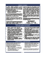
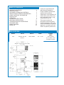
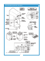
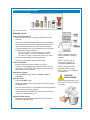
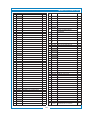
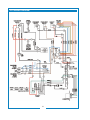
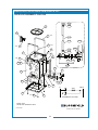
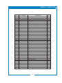
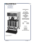
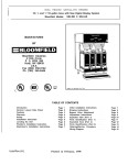
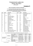
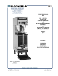
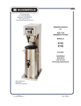
661
10 Sunnen Drive
St. Louis, MO 63143
telephone: 314-678-6336
fax: 314-781-2714
www.bloomfieldworldwide.com
OWNERS MANUAL
for
SS1 - SERIES
SATELLITE
COFFEE BREWERS
with
ELECTRO-MECHANICAL
CONTROL
and
INTERNALLY HEATED
SATELLITE SERVER
MODEL:
9311
Includes:
Installation
Operation
Use & Care
Servicing Instructions
Model 9311 Satellite Brewer
w/optional
3902 Drip Tray
p/n DD-74415 Rev. I M661 090724
TABLE OF CONTENTS
WARRANTY STATEMENT
SPECIFICATIONS
FEATURES & OPERATING CONTROLS
PRECAUTIONS & GENERAL INFORMATION AGENCY APPROVAL INFORMATION
INSTALLATION
OPERATION
CLEANING INSTRUCTIONS
SERVICING INSTRUCTIONS
TROUBLESHOOTING SUGGESTIONS
EXPLODED VIEW
WIRING DIAGRAM
SATELLITE
xi
1
2
4
4
5
7
9
11
16
18
20
21
Thank You for purchasing this
Wells Bloomfield appliance.
Proper installation, professional
operation and consistent
maintenance of this appliance will
ensure that it gives you the very
best performance and a long,
economical service life.
This manual contains the
information needed to properly
install this appliance, and to use,
care for and maintain or repair the
appliance in a manner which will
ensure its optimum performance.
SPECIFICATIONS
MODEL
VOLTS
WATTS
AMPS
POWER
CORD
9311
120/208 - 240 VAC
60 Hz 1ø
3200 - 4280W
15.4 - 17.8A
3-wire required
(L1, L2, Neut) + Gnd
Cord NOT Provided
1
FEATURES AND OPERATING CONTROLS
Fig 1. SS-1 Satellite Brewing System
Features & Operating Controls
2
FEATURES AND OPERATING CONTROLS (continued)
Brewer
Adjustable Legs
Allows brewer to be leveled. Also allow clearance for cleaning
underneath brewer.
Bypass Nozzle
Dilution water flows into satellite server from here.
Connector
Connects to satellite. Allows satellite heater to be energized.
Allows brewer to sense that a satellite is in place.
Hot Water Faucet
Hot water dispensed here.
Nameplate
Lists manufacturer, model and serial number.
Also lists voltage and wattage rating of brewer.
Control Panel
Brew Switch
Press to start a brew.
Ready to Brew Indicator
Glows when water in tank is up to temperature.
Stop Switch
Press to cancel a brew in progress.
Satellite Indicator
Glows when a satellite is properly installed.
Flashes at end of Quality Time.
Tank Heat Switch
Applies power to tank heater element. Glows when ON.
Volume Selector Switch
Allows selection if 1/2 gallon, 1 gallon or 1-1/2 gallon brew.
Brew Chamber
Brew Chamber
Holds coffee grounds during brew cycle.
Wire Rack
Holds paper filter and coffee grounds in proper position in brew
chamber.
Satellite
Brew-Thru Lid
Allows entry of brewed coffee and dilution water into satellite.
Minimizes splashing in the event satellite is tipped.
Connector
Connects to brewer. Allows heater to be energized. Allows
brewer to sense that a satellite is in place.
Handles
Allow the satellite to be safely carried.
Nameplate
Lists manufacturer, model and serial number.
Also lists voltage and wattage rating of satellite.
Serving Faucet
Fresh coffee dispensed from satellite here.
Sight Glass
Check the level of coffee remaining here.
Drip Tray (optional)
Optional drip tray catches drips and spills from serving faucet.
Easily removed for cleaning.
3
GENERAL INFORMATION AND PRECAUTIONS
WARNING:
SHOCK HAZARD
All servicing requiring access
to non-insulated electrical
components must be
performed by a factory
authorized technician.
DO NOT open any access
panel that requires the use
of tools. Failure to follow this
warning can result in severe
electrical shock.
CAUTION:
BURN HAZARD
Surfaces of the brewer and
brew chamber may be hot
to the touch and can cause
burns on contact.
This appliance is intended for use in commercial
establishments only.
This appliance is intended to brew hot beverage, specifically
coffee, for human consumption. No other use is recommended or
authorized by the manufacturer or its agents.
Operators of this appliance must be familiar with the appliance
use, limitations and associated restrictions. Operating instructions
must be read and understood by all persons using or installing this
appliance.
Cleanliness of this appliance is essential to good sanitation. Read
and follow all included cleaning instructions and schedules to ensure
the safety of the food product.
Surfaces of the brewer, brew chamber and satellite can be hot to the
touch, and may cause burns on contact.
Disconnect the brewer from electrical power before performing any
maintenance or servicing.
DO NOT submerge satellites in water.
DO NOT splash or pour water over, onto or into any controls,
control panel or wiring.
Any procedure which requires the use of tools must be performed
by a qualified technician.
This manual is considered to be a permanent part of the appliance.
This manual and all supplied instructions, diagrams, schematics,
parts breakdown illustrations, notices and labels must remain with
the appliance if it is sold or moved to another location.
This appliance is made in the USA. Unless otherwise noted, this
appliance has American sizes on all hardware.
AGENCY APPROVAL INFORMATION
This dual satellite brewing system is
and
listed under E9253
listed under E9253.
This dual satellite brewing system meets NSF Standard 4 only when
installed and maintained per the instructions in this manual.
4
INSTALLATION INSTRUCTIONS
INSTALL LEGS
The brewer is provided with adjustable legs and rubber feet. Be
sure the legs are securely screwed into the base of the brewer, and
that the rubber feet are properly installed.
LEVEL THE UNIT
The adjustable legs allow the brewer to be leveled. Set the brewer
in its ultimate operating location and check for level with a spirit
level Adjust the brewer for level from front-to-rear, and from sideto-side. Be sure all four feet rest firmly on the counter.
PLUMBER’S INSTALLATION INSTRUCTIONS
IMPORTANT:
This equipment must be installed in accordance with the Basic
Plumbing Code of the Building Officials and Code Administrators
International (BOCA), and the Food Service Sanitation Manual
of the Food and Drug Administration (FDA). Also, this equipment
installation must comply with all local plumbing codes and
ordinances.
IMPORTANT:
Brewer must be installed on a water line with a full-flow pressure
between 20 psi and 90 psi.
NOTE: If water pressure varies greatly, or exceeds 90 psi at any
time, a water pressure regulator must be installed. Plumbing
installer must supply the regulator.
Brewer must be connected to a potable water supply. Bloomfield
recommends not less than 1/4” copper tubing for installations of
12’ or less, and not less than 3/8” copper tubing for installations
exceeding 12’. Brewer must be connected to a COLD water line.
NOTE: DO NOT use a saddle tap for this water line connection.
A shut-off valve must be installed between the main water supply
and the brewer. Plumbing installer must supply the shut-off valve.
A 1/4-turn ball valve is recommended.
NOTE:
To enable the installer to make
a quality installation and to
minimize installation time, these
tests and suggestions should be
completed before the actual
installation is begun.
CAUTION:
UNSTABLE
EQUIPMENT HAZARD
Rubber feet must be installed
on each leg of the brewer. Legs
must be adjusted so that all four
feet rest firmly on the counter.
Failure to properly install the
feet can result in movement of
the brewer, which can cause
personal injury and/or damage
to the brewer.
CAUTION:
SHOCK HAZARD
Brewer must be properly
grounded to a reliable earth
ground to prevent possible
shock hazard. Do not assume
a plumbing line will provide
such a ground. Electrical shock
may cause serious injury.
Bloomfield highly recommends the use of the provided water
strainer to help prevent deposits in the brewing system.
Fig. 2 Adjustable Legs
Fig. 3 Water Line Installation
Flush the water line before connecting to the brewer.
5
INSTALLATION INSTRUCTIONS (continued)
CAUTION:
SHOCK HAZARD
ELECTRICIAN’S INSTALLATION INSTRUCTIONS
Refer to Electrical Specifications, page 1.
Brewer must be
properly grounded to a reliable
earth ground to prevent possible
shock hazard. Do not assume a
plumbing line will provide such
a ground. Electrical shock may
cause serious injury.
Brewer requires a dedicated single-phase circuit:
IMPORTANT:
Initial set-up must be performed
by a qualified installer or
qualified service technician.
Improper set-up will damage the
brewer and void the warranty.
INITIAL SET-UP INSTRUCTIONS
IMPORTANT:
Complete water line installation
before connecting brewer to
electrical power.
1. CHECK BREWER FOR PROPER CONFIGURATION
Make sure spray disk gasket is in place INSIDE of spray head.
MAKE SURE THE FRONT
PANEL “TANK HEATER”
SWITCH IS IN THE
OFF
POSITION BEFORE
CONNECTING BREWER TO
ELECTRICAL POWER.
DO NOT turn the TANK
HEATER switch on until the
water tank is filled. Heating
element must be completely
submerged in water at all
times. Damage to the brewer
caused by operating the heating
elements dry is NOT covered by
warranty.
Model 9311
120/240 Volt AC, 50/60 Hz 4-Wire 20 Amps.
Plumber’s and Electrician’s installation procedures must be
completed before proceeding with the set-up.
Be sure all electrical connections are secure, and that all
plumbing connections are secure and leak-proof.
Make sure spray disk is properly installed.
Check hot water faucet for proper operation.
2. FILL WATER TANK
Be sure TANK HEATER switch is OFF, then connect brewer to electric power.
Insert an empty brew chamber under the brew head. Place an empty satellite in position. Turn the VOLUME SELECTOR
switch to 1 GAL.
Press START. Water will begin filling the tank. Repeat until water flows from the brew chamber. For initial start-up, tank requires two or more 1 GAL. cycles to fill.
3. CHECK HEATING
Press TANK HEATER switch ON. Water in tank will heat to brewing temperature in approximately 30 minutes. When the water temperature reaches the brew temperature set
point, the READY-TO-BREW light will glow.
Hold a suitable container under the hot water faucet, then open the faucet . Continue drawing water until all trapped air is expelled.
6
OPERATING INSTRUCTIONS
Fig. 4 Control Panel
BREWING COFFEE
Prepare the Brew Basket:
Make sure the wire rack is properly installed in the brew
chamber.
Insert one (1) Bloomfield paper filter into the brew chamber. Make sure the filter is properly supported by the wire rack.
Add a measured amount of grounds to the brew basket.
Recommendations (may vary, depending on type of coffee and personal taste preferences):
To brew 1/2 gallon, use 2.25 oz (64 gm) of coffee
To brew 1 gallon, use 4.50 oz (128 gm) of coffee
To brew 1-1/2 gallon, use 8.40 oz (240 gm) of coffee
Gently shake the basket to level the grounds.
Fig. 5 Brew Basket
NOTE: Brewer will not brew
unless a satellite is properly
installed.
Slide the brew chamber under the brew head.
NOTE: The brew can be
cancelled at any time by
pressing the STOP switch.
Insert the Satellite:
Brewer will not brew unless a satellite is properly
installed. Slide satellite under the brew chamber until it is fully seated. The SATELLITE indicator will glow when the satellite is properly positioned.
Select Brew Volume:
Turn VOLUME SELECT switch to 1/2 GAL, 1 GAL or
1-1/2 GAL.
NOTE: DO NOT turn the
VOLUME SELECT switch
during a brew. This will disrupt
the brew cycle.
Start the Brew:
Press the START switch.
NOTE: The brew can be cancelled at any time by pressing the STOP switch.
At the end of the brew, be sure all water has stopped dripping before removing the brew chamber.
When the READY-TO-BREW light comes on, the brewer is ready to run another brew cycle.
Empty the Brew Basket:
Discard the grounds and the paper filter. Rinse the brew chamber under clear water.
7
CAUTION:
BURN HAZARD
Basket and contents are hot to
the touch and may cause burns
on contact.
OPERATING INSTRUCTIONS (continued)
Fig. 6 Water Flow Diagram
The time the BREW
SOLENOID is open is
controlled by the TIMER
in response to the
position of the VOLUME
SELECTOR switch.
BREW & BYPASS
The SS-1 is a modified displacement brewer.
The BREW SOLENOID
has two sections:
.19 GPM (1/2 and 1 gal)
.33 GPM (1-1/2 gal)
In 1-1/2 gallon mode, a portion if the heated water is diverted to the
satellite through the BYPASS SOLENOID and BYPASS NOZZLE.
NOTE: Use of the faucet
will not affect the volume
of water delivered for a
brew. However, overuse
of the faucet during a
brew may lower the
temperature of the brew
water.
For 1/2 and 1 gallon brews, there is no bypass. Water admitted into
the hot water tank by the BREW SOLENOID will displace a like amount
of heated water through the brew head, brew chamber and into the
satellite.
The solenoid has two separately controlled sections to provide more
precise control of delivered water volumes in bypass and non-bypass
modes.
HOT WATER FAUCET
Water for the hot water faucet is heated in a coil inside of the water
tank. The faucet volume may be controlled by adjusting the FAUCET
NEEDLE VALVE. Hot water is delivered at inlet line pressure and is
approximately the same temperature as the brew water.
8
CLEANING INSTRUCTIONS
CLEANING
INSTRUCTIONS
PROCEDURE: Clean Coffee Brewer
CAUTION:
BURN HAZARD
PRECAUTIONS: Press POWER key to OFF.
Allow brewer to cool.
FREQUENCY: Daily
TOOLS: Mild Detergent, Clean Soft Cloth or Sponge
Bristle Brush
IMPORTANT:
1. Press POWER key to OFF.
Brewing and serving
temperatures of coffee are extremely hot.
Hot coffee will cause
serious skin burns.
Allow brewer to cool.
2. Remove satellites.
3. Remove and empty brew baskets.
4. Remove spray disks and gaskets from spray heads
5. Wipe inside of spray head and area around spray head with a
soft clean cloth or sponge moistened with clean water.
6. Wash spray disks in a sink using warm water and a mild detergent. A bristle brush may be used to clear clogged spray
holes. Rinse spray disks with clean water and allow to air
dry.
7. Wash brew baskets in a sink using warm water and a mild
detergent. A bristle brush may be used to clean around the
wire racks and bypass channels. Rinse with clean water and
allow to air dry. Be sure wire racks are properly installed.
8. Remove and drain the drip tray. Rinse in a sink under warm running water. Allow to air dry, then reinstall on brewer.
9. Wipe exterior of brewer and satellites with a soft clean cloth or sponge moistened with clean water.
10. Reinstall gaskets INSIDE brew heads, then reinstall spray
disks.
11. Reinstall brew chambers.
12. Reinstall satellites.
Procedure is complete
9
DO NOT use steel wool, sharp
objects, or caustic, abrasive or
chlorinated cleansers to clean
the brewer, brew baskets or
satellites.
DO NOT immerse or submerge
satellites in water.
CLEANING INSTRUCTIONS (continued)
CAUTION:
BURN HAZARD
Brewing and serving
temperatures of coffee are extremely hot.
Hot coffee will cause
serious skin burns.
WARNING:
SHOCK HAZARD
DO NOT immerse or submerge
satellites. Fluid may saturate
the insulation and short-circuit
the receptacle connectors.
Electric shock may cause injury
and property damage.
IMPORTANT:
DO NOT use steel wool, sharp
objects, or caustic, abrasive or
chlorinated cleansers to clean
the satellites.
PROCEDURE: Clean Satellite
PRECAUTIONS: Drain Satellite before Cleaning
FREQUENCY: Twice Weekly
TOOLS: Sight Glass Brush, Sanitizer
Soft Clean Cloth, Bucket
1. Remove and drain satellites.
2. Place 1 packet of Sanitizer into 2-1/2 gallons of warm tap
water. Pour approximately 1 gallon of sanitizer solution into each satellite. Allow to stand for 2 minutes.
3. Remove the shield cap (large vent) on top of the sight glass.
NOTE: It is not necessary to remove the sight glass unless it
is broken and replacement is required.
4. Run the sight glass brush up and down through the sight
glass at least 10 times.
5. Reinstall and tighten the shield cap.
6. Drain sanitizer solution from satellite into the bucket.
7. Disassemble faucet. Brush clean with sanitizer solution.
Reassemble faucet.
8. Install satellite on brewer.
9. Rinse satellites: With an empty brew chamber in place,
press the BREW key and run 1 full cycle into each satellite.
10. Drain water from satellites.
Procedure is complete
10
SERVICING INSTRUCTIONS
TEMPERATURE ADJUSTMENT
Energize brewer and allow unit to heat. When the READY TO
BREW light first glows, read the temperature.
Thermostat may be adjusted by removing the right button plug.
Carefully check the water temperature at the outlet of the brew
chamber. The temperature at this location is approximately 5º F
less than the actual brew temperature.
Adjust thermostat by turning shaft; clockwise increases
temperature. 1/8 turn = approximately 10ºF, or 5.6ºC.
Refer to Table 1 below for proper brewing temperature based on
altitude.
Upon completion, remove thermometer and reinstall the vent line
and top wrap.
Table 1
CAUTION:
SHOCK HAZARD
Live electrical circuits are
exposed during this procedure.
Use care to avoid uninsulated
electrical connectors.
NOTE: Optimum brewing
temperature is 195ºF to 205ºF
(90ºC to 96ºC).
Thermostat should be adjusted
to a maximum temperature of
200ºF (95ºC).
IMPORTANT:
A mechanical thermostat will
maintain temperature within
±5ºF.
To prevent boiling water in
the brewer, controller should
be adjusted to a maximum
temperature equal to the local
boiling temperature minus 5ºF,
or 205ºF (97ºC), whichever is
less.
NOTE: 1/8 turn = approximately
10ºF (5.6ºC).
Boiling Temperature by Altitude
Fig. 10 Adjust Thermostat
11
SERVICING INSTRUCTIONS (continued)
CAUTION:
SHOCK HAZARD
Disconnect brewer from electric
power before opening the
access panel.
Adjustments to be performed by
qualified technician only.
NOTE:
Brewer is pre-adjusted to deliver
1/2, 1 and 1-1/2 gallons of
coffee at a water pressure of
50 p.s.i. Use this procedure to
adjust the delivered volume to
suit local conditions.
BREW TIMER ADJUSTMENT
PRECAUTIONS: Disconnect brewer from electric power.
Allow brewer to cool.
FREQUENCY: As required to adjust delivered volume
TOOLS: Phillips head screwdriver
Small flathead screwdriver
Satellite or other container to calibrate volume
1. Press HEATER ON/OFF switch to OFF. Disconnect brewer from electrical power.
2. Remove TOP PANEL. Operating controls are accessible through the top panel only.
3.
Adjust the BREW TIMER setting.
NOTE: Each volume has its own setting:
L = 1-1/2 gallon (adjusts from 218 to 398 seconds)
M = 1 gallon (adjusts from 252 to 372 seconds)
S = 1/2 gallon (adjusts from 92 to 212 seconds)
Turn CLOCKWISE to increase time;
Turn COUNTER-CLOCKWISE to decrease time.
Adjust only in small increments to avoid large volume
variations. Recommend adjustments be made in 1/32 turn increments, and no more than 1/16 turn at a time.
4. Replace TOP PANEL. Turn TANK HEATER switch ON. Reconnect brewer to electrical power.
5. Allow the brewer to come up to brewing temperature, then perform a test brew. Check delivered volume. Readjust as necessary.
When desired volume is achieved, procedure is complete.
12
SERVICING INSTRUCTIONS (continued)
QUALITY TIMER ADJUSTMENT
CAUTION:
PRECAUTIONS: Disconnect brewer from electric power.
Allow brewer to cool.
FREQUENCY: As required to adjust delivered volume
TOOLS: Phillips head screwdriver
Satellite or other container to calibrate volume
1. Press HEATER ON/OFF switch to OFF. Disconnect brewer from electrical power.
2. Remove TOP PANEL. Operating controls are accessible through the top panel only.
3.
Adjust the QUALITY TIMER setting.
Turn CLOCKWISE to increase time;
Turn COUNTER-CLOCKWISE to decrease time.
Adjustment range is from 30 to 120 minutes.
4. Replace TOP PANEL. Turn TANK HEATER switch ON. Reconnect brewer to electrical power.
Procedure is complete
SHOCK HAZARD
Disconnect brewer
from electric power before opening the
access panel.
The QUALITY TIMER flashes
the SATELLITE light at the end
of the set interval to signal that
the coffee has lost freshness.
Discard the coffee in the
satellite and either brew a fresh
batch or clean the satellite for
future use.
Quality time interval begins
when the brew switch is
pressed.
When the light is flashing,
coffee will continue to be
maintained at temperature until
the satellite is removed from the
brewer.
Removing the satellite for
5 seconds will reset the timer.
13
SERVICING INSTRUCTIONS (continued)
CAUTION:
CHEMICAL BURN
HAZARD
Deliming chemicals are caustic.
Wear appropriate protective
gloves and goggles during this
procedure.
Never siphon deliming
chemicals or solutions by
mouth.
This operation should only be
performed by qualified and
experienced service personnel.
PROCEDURE: Delime the Water Tank
PRECAUTIONS: Disconnect brewer from electric power.
Allow brewer to cool.
FREQUENCY: As required (Brewer slow to heat)
TOOLS: Deliming Solution
Protective Gloves, Goggles & Apron
Mild Detergent, Clean Soft Cloth or Sponge
Bristle Brush, Bottle Brush
Large Sink (or other appropriate work area)
IMPORTANT: DO NOT spill,
splash or pour water or deliming
solution into or over any internal
component other than the inside
of the water tank.
1. Disconnect brewer from the electrical supply.
2. Remove the brewer top panel, then remove the tank lid assembly. Do not disconnect the tank assembly at this time.
3. Siphon all water from the hot water tank.
IMPORTANT: DO NOT allow
any internal components to
come into contact with the
deliming solution. Take care to
keep all internal components
dry.
NOTE: Repeat steps 4 and 7
as required to remove all buildup.
4. Mix 10 gallons of deliming solution according to the
manufacturer’s directions. Carefully pour the deliming solution into the water tank. Lower the lid assembly back onto the tank. Allow to sit for 30 minutes, or as directed by the chemical manufacturer.
5. At end of soaking period, reconnect brewer to electrical power. Install the brew chamber without filter paper or grounds. Place an empty satellite under the brew
chamber. Force a 1-1/2 gallon brew:
a. Press the 1-1/2 gallon key
b. Press the brew key, then press and hold the brew key until a brew is initiated.
Empty the satellite and repeat for the other side.
6. Disconnect brewer from electrical power and allow to cool.
7. Remove lid assembly from tank.
a. Using a stiff bristle brush, scrub internal components to remove lime and calcium build-up.
b. Thoroughly rinse internal components of lid assembly with clear water.
c. Store lid assembly in a safe location.
8. Using a stiff bristle brush, scrub exposed portions of the heating element and the inside surfaces of the tank to
remove lime and calcium build-up.
9. Siphon all solution from the tank.
14
SERVICING INSTRUCTIONS (continued)
10. Reinstall tank lid assembly into hot water tank. Make sure the lid gasket is properly in place, then reinstall the hold-
down clamps.
11. Remove spray disks and gaskets. Rinse both brew heads with clean water. Using a stiff brush, scrub spray disk to remove any lime or calcium build-up. Reinstall gaskets and spray disks.
13. Reconnect brewer to electrical supply .
14. Install the brew chamber without filter paper or grounds.
15. Place an empty satellite under the brew chamber. Run at least five 1-1/2 gallon brew cycles and discard all water generated at the end of each cycle.
Repeat for the other side.
16. Rinse satellite with clean water. Reinstall one empty
satellite under each brew chamber.
Brewer is ready to use.
15
NOTE: Normally, silicone
hoses do not need to be
delimed. Should deliming hoses
become necessary, Bloomfield
recommends replacing the
hoses.
TROUBLESHOOTING SUGGESTIONS
SYMPTOM
Will not heat or brew
(no lights)
Will not brew
Brewer fails to heat
Brewer fails to stop
brewing after STOP
switch pressed
Coffee overflows
from brew chamber
Insufficient brew
volume
(all volumes)
Satellite overflows
(1-1/2 gal brew only)
POSSIBLE CAUSE
SUGGESTED REMEDY
Brewer not plugged in or circuit
breaker tripped
Reconnect brewer to electric power
Reset circuit breaker
Fuse blown
Check satellite for water saturation
Replace fuse
Satellite is not in proper position
Reinstall satellite. Satellite light should
be on
Brew switch damaged
Check. Replace if needed
Timer damaged
Check. Replace if needed
Volume selector switch damaged
Check. Replace if needed
Satellite connector snap-action switch
damaged
Check. Replace if needed
Tank heat switch off
Turn tank heat switch on
Hi-limit tripped
Allow to cool, reset hi-limit
Thermostat out of adjustment or
damaged
Check. Adjust or replace as needed
Satellite receptacle or brewer
connector damaged
Check connectors. Be sure all pins are
in place and tight. Replace if needed
Switch not pressed long enough or
firmly enough
Switch must be pressed firmly for at
least 1 second
Stop Brew switch damaged
Check. Replace if needed
Brew solenoid damaged or dirty
Check. Clean or replace as needed
Too much coffee or too fine a grind
Use proper amount and grind of coffee
grounds per brew
More than 1 filter paper or wrong type
of filter paper used
Use 1 genuine Bloomfield filter paper per
brew
Timer out of adjustment or damaged
Check time. Adjust or replace as
needed
Brew solenoid damaged
Check. Replace if needed
Wire rack missing from brew chamber
Check. Replace if needed
Low inlet water pressure
Other appliances on water line may be
robbing pressure. Brewer should be on
dedicated water line
Inlet strainer plugged
Clean strainer
Timers out of adjustment
Adjust time for each brew volume
Timer damaged
Check. Replace if needed
Bypass solenoid damaged
Check. Replace if needed
16
TROUBLESHOOTING SUGGESTIONS (continued)
SYMPTOM
Insufficient brew volume
(any one volume only)
Insufficient brew volume
(1-1/2 gallon brew only)
POSSIBLE CAUSE
Timer out of adjustment
Adjust time for each brew volume
Timer damaged
Check. Replace if needed
Volume select switch damaged
Check. Replace if needed
Timer out of adjustment
Adjust time for each brew volume
Bypass solenoid damaged
Check. Replace if needed
Volume select switch damaged
Check. Replace if needed
Satellite not in proper position
Reinstall satellite.
Satellite light neither lit
Satellite receptacle or brewer
nor flashing with satellite connector damaged
in place
Connector snap-action switch
damaged
Satellite light on with no
satellite in place
Satellite light flashes
constantly
Ready light does not
glow
Constant drip from brew
head
Poor spray pattern from
spray disk
No water from faucet
Faucet drips
Poor coffee quality
SUGGESTED REMEDY
Check connectors. Be sure all pins
are in place and tight. Replace if
needed
Check. Replace if needed
Connector snap-action switch
damaged
Check. Replace if needed
Quality hold time exceeded
Discard coffee, brew fresh
Remove satellite for 5 seconds to reset
Satellite was in place when power
was turned on
Remove satellite. Turn brewer off for 5
seconds, turn on then reinstall satellite
Quality timer damaged
Check. Replace if needed
Light damaged
Check. Replace if needed
Brew solenoid dirty or damaged
Check. Clean or replace as needed
Faucet coil leaking.
Check by turning faucet valve off. If
leak stops, replace coil
Thermostat set too high
Set per chart on page 11.
Spray disk holes plugged
Check. Clean as needed
Gasket missing or improperly
installed
Reinstall gasket inside brew head
Low inlet water pressure
Other appliances on water line may be
robbing pressure. Brewer should be
on dedicated water line
Faucet valve off
Valve must be on for flow from faucet
Debris in faucet
Disassemble and clean faucet
Water pressure too high
Install pressure regulator in incoming
water line
Keep brewer and satellites clean. Install a taste and odor filter in water
supply, and replace cartridges regularly.
Use a quality coffee with a consistent roast. Use proper grind and amount of
coffee per brew.
17
MODEL 9311 EXPLODED VIEW
ALT
14
Model: 9311
SATELLITE COFFEE BREWERS: 9311
PL661
IL1842 Rev. A 7/23/09
18
MODEL 9311 PARTS LIST
Fig No
1
Part No
2C-70379
2
Description
SCREW 8-32X5/16 PH PAN MS
BASE WELDED ASSY
Qty
Fig
No.
24
Part No.
Description
Qty
1
48
2N-70149
COIL ASSY HOT WATER
1
2I-70152
GASKET ELEM HTG
1
3
2K-70154
FTG UNION 1/4X1/4
1
49
4
DD-72491
COVER BASIN (TOP PANEL)
1
50
2V-70352
VALVE NEEDLE SEAT
1
5
2C-70175
NUT 1/2-20 HEX HD BRASS
2
51
2C-70151
NUT 7/16-20 HEX HEAD BRASS
2
6
2E-70451
CONNECTOR BRASS, FEMALE TO MALE
1
52
DD-73150
TUBE ASSY FAUCET COIL, COPPER
1
7
2C-70467
CLIP BREW BASKET
1
53
ELBOW OUTLET
1
8
2C-70135
SCREW 10-32X1 PH PAN HD
1
9
2C-70134
STRAP HOLD DOWN ASSY
1
10
2C-70132
NUT INNERMAN 8-32
14
2K-70103
WS-851251
WS-86280
11
2E-70477
CONNECTOR 1/4 MALE FLARE
1
12
2K-70478
FTG ELEBOW
1
13
DD-70197
TUBE INLET ASSY (SHORT), SOLENOID
1
14
2C-70174
WASHER THERMO SEAL .465 OD
15
A6-74405
TUBE SIL .312 ID X 2.1
1
16
2K-72241
FTG HOSE CONNECTOR STRIAGHT
1
17
2D-73101
CHAMBER BREW .187 HOLE NO
1
18
DD-73060
LIGHT SALELLITE AMBER 120
1
19
2V-72400
TUBE TANKS TO SPRAY HEAD
1
20
2K-73152
ELBOW SPRAYER 1/4 ID
1
TOP HOUSING WLD ASSY
1
21
22
2K-70229
BUSHING SHORTY HEYCO
1
23
2I-70139
GASKET SPRAY HEAD
1
24
A6-74132
SPRAY HEAD DISC EMBOSSED .051
1
25
DD-72728
SWITCH ROTARY W/HARNESS
1
26
2E-73120
SWITCH START BREW 125/250
1
27
DD-73149
TIMER 30-120MIN QUALITY
1
28
2J-70644
LIGHT PILOT GREEN 250V
1
29
2E-71259
SWITCH NORM ON-MOMENT OFF
1
30
2E-72395
SWITCH ROCKER 250V 20A
1
31
WS-82556
FAUCET ASSY PRESSURE N/S
1
32
2C-72681
WASHER FAUCET
1
33
2C-70107
WASHER LOCK 7/16 EXT SEMS
1
34
2C-72680
NUT 7/16-20 FINISHED HEX
1
35
2B-70466
RACK WIRE BREW CHAMBER
1
36
2C-70115
SCREW 10-32X5/16 HEX HD
1
37
DD-72388
TUBE FILL 90DEG BEND W/
1
38
2R-70112
HANDLE BLACK
1
39
A6-73537
TUBE SIL .312 ID X 9” LG
1
40
2I-72390
GROMMET .375 ID TRANSLUCENT
1
41
2V-72729
VALVE ADJUST DISPENSING
1
42
DD-74400
BRKT DOUBLE SOLENOID
1
43
2R-72397
KNOB ROTARY SWITCH SKIRT
1
44
DD-73059
GUIDE BASE SS1-ADT
1
BRACKET TANKS SUPPORT
45
46
2E-75143
SOLENOID DUAL 120V .33/.1
47
DD-74406
TUBE SIL .312 ID X 2.5
55
2V-70398
THERMOSTAT, CONTRROL BREWERS
T-STAT COTHERM SUBST 851
(ALTERNATE)
TUBE VENT LONG
56
2A-77260
SLEEVE THERMOSTAT BULB 11”
1
57
DD-72495
COVER TANK SS-1
1
58
GASKET TANK COVER
1
ELEM 240V 4200W
1
60
2I-70147
WS-876044
2C-35485
NUT 1/4-20 HEX FINISHED
1
61
2C-73457
NUT 8-32 HEX HEAD KEPS MS
19
62
DD-72732
54
59
1
2
TANK WLD ASSY SS1
1
63
PANEL FRONT
1
64
BASE COVER ASSY
1
SWITCH SNAP ACTION SDS-2
1
BRACKET CONNECTIOR
1
65
DD-83105
66
67
BOTTOM PLATE ASSY
1
68
D7-72738
SPOUT ASSY
1
69
2T-70716
THERMO HI LIMIT RESET 240
1
70
DD-72735
BODY WELDED ASSY
1
71
2P-72736
TIMER 3 LEVEL
1
72
2A-73098
LEG 4 BLK PLASTIC W/FLAN
4
73
2E-70709
TERM BLOCK 4 POLE
1
74
2V-73027
STRAINER “Y” PLASTIC W/FT
1
75
DD-72739
NUT TANK FITTING #304 3/4
1
76
A6-73537
TUBE SIL .312 ID X 9 LG
1
77
A6-73100
BREW CHAMBER ASSY SS1 .18
1
78
DD-72514
TUBE ASSY COPPER INLET
1
79
DD-71357
TUBE ASSY INLET
1
80
2C-70512
WASHER SS .035X7/16IDX3/4
1
81
2C-70155
NUT 7/16-20 HEX HD BRASS
1
82
DD-73151
BRKT ADAPTOR BYPASS SS1
1
83
2C-35530
SCREW 8-32X3/8PH RD #23SE
3
84
DD-72589
BRKT TANK SUPPORT TOP
1
85
2K-72720
FTG TEE BARB
1
90
2V-70111
TUBE FORMED INLET ASSY
1
91
F4-70409
WASHER BEVELLED
1
92
DD-76934
FTG ELBOW W/EXTENSION
1
1
93
2E-73046
CONNECTOR WIRED ASSY SDS
1
97
2K-46385
FTG CONDUIT STRAIGHT 3/4
1
1
99 2C-73147
WASHER GYLON 1/2 ID 3/4 OD
3
19
MODEL 9311 PARTS LIST
Fig
No.
100
2C-73148
WASHER GYLON 7/16 ID 3/4
2
101
A6-70088
DOOR ACCESS SOLENOID
1
102
DD-83104 SPACER TIMER W/LOCK NUT #8-32
Part No.
103
Description
Qty
4
NUT LOCK HEX #8-32
104
2A-73107
105
DD-71265 FUSEHOLDER
FEET RUBBER BLACK
1
106
DD-71266 FUSEHOLDER
1
107
DD-73182 RELAY 30 AMP
1
108
2I-73570
1
INSERT BYPASS REG. SS2
4
ACCESSORIES
WS-3902
TRAY DRIP SS1
1
FAUCET REPAIR KITS
WS-82573 HANDLE RED FAUCET
WS-82575 SEAT CUP FAUCET N/S
WS-82576 KIT FAUCET HANDLE ASSY
WS-82682 CLIP FAUCET
WS-84804 KIT STREAM FORMER PRESS FAUCET
20
9311 WIRING DIAGRAM
21
9340 SATELLITE EXPLODED VIEW & PARTS LIST
SATELLITE ASSEMBLY 9340 120V
10.01
10.02
1
13
2
2 PL
10.03
10.04
5
3 PL 33
10.30
4 PL
26
7
10.05
10.06
9
28
10.10
8
4 PL 30
10.08 10.09
27 21
4 PL
10.20
6
18
14
10
24
15
19
20
12
21
22
23
5
4 PL
L1
45W
16
4 PL 25
17
SCHEMATIC P/N 73061
Model: 9340
SATELLITE INTERNAL HEAT
PL691.9340
IL1843 Rev. A 7/24/09
22
NEUT.
MODEL 9311 PARTS LIST
ITEM
PART NUMBER
DESCRIPTION
QTY
1
2L-73863
TANK LID ASSY
1
2
2R-73099
HANDLE, SATELLITE TOP
2
SCREW, 8-32x3/8“ BLK OXIDE
8
STIFFENER BRACKET, LEFT
1
TOPCOVER, SATELLITE
1
FRAME, DECAF (PART OF #9)
1
5
6
7
2L-73558
8
9
DD-83092
DOOR, DECAF
1
10
2U-73112
FAUCET w/SIGHT GLASS, 10“
1
10.01
WS-8600-17
SHIELD CAP
1
10.02
WS-8500-25J
CAP WASHER
1
10.03
WS-8705-11C
SIGHT GLASS
1
10.04
WS-8600-20
SHIELD ASSY
1
10.05
WS-8705-11B
BASE WASHER
1
10.06
WS-8705-11G
SHIELD BASE
1
10.08
WS-8600-26
C-RING
1
10.09
WS-8600-27
WING NUT
1
10.1
2U-71460
SEAT CUP
1
10.2
WS-8705-11D
SHANK ASSY
10.3
N.L.A.
FAUCET & HANDLE ASSY COMPLETE
12
DD-74326
HANDLE GUARD, FAUCET
1
13
WS-83172
RECEPTICAL, WIRED ASSY
1
14
N.L.A.
ELEMENT, HEATER, 45W
1
15
D7-73117
TANK INSULATION
1
16
2L-73057
BASE, POLYPROPYLENE
1
17
PLATE STIFFENER
1
18
WELDEMENT, SATELLITE BODY
1
19
TANK SUB ASSY w/FITTINGS
20
TAPE, GLASS CLOTH
0.33
THREADLOCK, RED
A/R
21
22
2I-70801
SEAL, DRAIN FITTING
1
2
23
TAPE, TEFLON
24
LABEL, SATELLITE
1
25
SCREW, PAN PHL 8-32x1/2“
4
26
STIFFENER BRACKET, RIGHT
1
27
SCREW, TRS PHL SS 10-32x3/8“
4
O-RING
1
WASHER #10
4
28
2I-70812
30
1.74
33
2C-73457
NUT, KEP SS 8-32
3
34
2M-73132
LABEL, CAUTION “DO NOT IMMERSE...”
1
23
10 Sunnen Drive, St. Louis, MO 63143
telephone: 314-678-6336 fax: 314-781-2714
www.bloomfieldworldwide.com