1
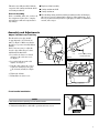
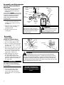
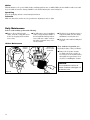
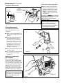
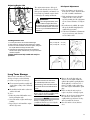
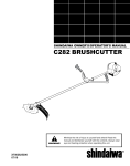
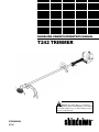
SHINDAIWA OWNER’S/OPERATOR’S MANUAL
T242 TRIMMER
WARNING!
Minimize the risk of injury to yourself and
others! Read this manual and familiarize yourself with
the contents. Always wear eye and hearing protection
when operating this unit.
X7502800900
07/10
Introduction
The Shindaiwa 242 Series hand
held power equipment has been
designed and built to deliver superior
performance and reliability without
compromise to quality, comfort, safety
or durability.
Shindaiwa engines represent the leading
edge of high-performance engine
technology, delivering exceptionally
high power with remarkably low
displacement and weight. As an owner/
operator, you’ll soon discover for
yourself why Shindaiwa is simply in a
class by itself!
Contents
IMPORTANT!
The information contained in this
owner’s/operator’s manual describes
units available at the time of publication.
Echo, Inc. reserves the right to
make changes to products without prior
notice, and without obligation to make
alterations to units previously
manufactured.
PAGE
Attention Statements............................ 2
Safety Instructions................................ 2
Safety Labels.......................................... 4
Product Description.............................. 5
Specifications......................................... 6
Emission Control.................................. 6
Attention Statements
Throughout this manual are special
“attention statements”.
DANGER!
A statement preceded by
the triangular attention symbol and
the word “DANGER” contains information that should be acted upon to
prevent serious injury or death.
WARNING!
The engine exhaust from
this product contains chemicals
known to the State of California to
cause cancer, birth defects or other
reproductive harm.
PAGE
Assembly and Adjustments.................. 7
Mixing Fuel........................................... 9
Filling the Fuel Tank.......................... 11
Starting the Engine............................. 12
Stopping the Engine........................... 12
Checking Unit Condition................... 12
WARNING!
A statement preceded by
the triangular attention symbol and
the word “WARNING” contains information that should be acted upon to
prevent serious bodily injury.
IMPORTANT!
A statement preceded by the word
“IMPORTANT” is one that possesses
special significance.
PAGE
Cutting Grass with a Trimmer Head.. 13
Maintenance........................................ 13
Long Term Storage............................. 17
Troubleshooting Guide...................... 18
Warranty Statement............................ 21
CAUTION!
A statement preceded by the
word “CAUTION” contains information that should be acted upon
to prevent mechanical damage.
NOTE:
A statement preceded by the word
“NOTE” contains information that is
handy to know and may make your job
easier.
IMPORTANT!
The operational procedures described in this manual are intended to help you get the most from this unit as well as to protect
you and others from harm. These procedures are guidelines for safe operation under most conditions, and are not intended to
replace any safety rules and/or laws that may be in force in your area. If you have questions regarding your 242 series hand
held power equipment, or if you do not understand something in this manual, your Shindaiwa dealer will be glad to assist you.
You may also contact Shindaiwa at the address printed on the back of this Manual.
Warning and Operational Labels
Read and follow this operator's
manual. Failure to do so could
result in serious injury..
Wear eye and hearing protection
at all times during operation of
this unit. Wear head protection
where there is a risk of falling
objects.
2
50 FEET
(15m)
Make sure no one is
within 15 M / 50 feet of an
operating machine.
Beware of thrown or
richocheted objects
WARNING: Surface can
be hot. Always wear
gloves when handling
this unit.
Do not use blades.
String line only
Safety Instructions
Work Safely
Shindaiwa trimmers operate at very
high speeds and can do serious damage
or injury if they are misused or abused.
Never allow a person without training or
instruction to operate this unit!
WARNING!
Never make unauthorized
attachment installations. Do
not use attachments not approved
by Shindaiwa for use on this unit.
Stay Alert
You must be physically and mentally fit
to operate this unit safely.
WARNING!
�
Never operate
power equipment of any
kind if you are tired or if you are
under the influence of alcohol,
drugs, medication or any other
substance that could affect your
ability or judgement.
DO NOT OPE
IF YOU ARE
UNDER THE
ALCOHOL, D
MEDICATION
�
�
�
WARNING!
Minimize the Risk of Fire
NEVER smoke or light fires near
the engine.
ALWAYS stop the engine and allow
it to cool before refueling. Avoid
overfilling and wipe off any fuel that
may have spilled.
ALWAYS inspect the unit for fuel
leaks before each use. During each
refill, check that no fuel leaks from
around the fuel cap and/or fuel tank.
If fuel leaks are evident, stop using
the unit immediately. Fuel leaks must
be repaired before using the unit.
ALWAYS move the unit to a place
well away from a fuel storage area
or other readily flammable materials
before starting the engine.
NEVER place flammable material
close to the engine muffler.
NEVER operate the engine without
the spark arrester screen in place.
Safety Instructions
WARNING!
Use Good Judgment
ALWAYS wear eye protection to
shield against thrown objects.
NEVER run the engine when
transporting the unit.
NEVER run the engine indoors! Make
sure there is always good ventilation.
Fumes from engine exhaust can cause
serious injury or death.
ALWAYS clear your work area of trash
or hidden debris that could be thrown
back at you or toward a bystander.
ALWAYS use the proper cutting tool
for the job.
ALWAYS stop the engine
immediately if it suddenly begins to
vibrate or shake. Inspect for broken,
missing or improperly installed parts
or attachments.
NEVER extend trimming line beyond
the length specified for your unit.
ALWAYS keep the unit as clean
as practical. Keep it free of loose
vegetation, mud, etc.
ALWAYS hold the unit firmly
with both hands when cutting or
trimming, and maintain control at all
times.
ALWAYS keep the handles clean.
ALWAYS disconnect the spark plug
wire before performing any
maintenance work.
ALWAYS, if a saw blade should
bind fast in a cut, shut off the engine
immediately. Push the branch or
tree to ease the bind and free the
blade.
3
Safety Labels
This label indicates the minimum distance between
front handle and rear grip per ANSI B175.3.
IMPORTANT!
Safety and Operation Information Labels: Make sure all
information labels are undamaged and readable. Immediately
replace damaged or missing information labels. New labels are
available from your local authorized Shindaiwa dealer.
Figure 1
The Properly Equipped Operator
Wear hearing protection devices and a
broad-brimmed hat or helmet. A helmet
is required when using a blade-equipped
brushcutter to clear small trees.
Prolonged exposure to excessive noise
is fatiguing and could lead to impaired
hearing.
Wear close-fitting clothing to
protect legs and arms. Gloves
offer added protection and are
strongly recommended. Do not
wear clothing or jewelry that
could get caught in machinery
or underbrush. Secure long hair
so that it is above shoulder level.
NEVER wear shorts!
Long-term exposure to vibration
can damage your hands.
Keep a proper footing and do not
overreach. Maintain your balance at all
times during operation.
Wear appropriate footwear (non-skid
boots or shoes): do not wear opentoed shoes or sandals. Never work
barefooted!
4
Always wear eye protection such as
goggles or safety glasses to shield
against thrown objects.
Always wear a harness when operating the unit .
It adds comfort and helps ensure safety by limiting
movement fore and aft. When the harness is
adjusted properly, the unit should balance with the
cutting attachment parallel to the ground.
Always operate with both hands
firmly gripping the unit.
Always make sure the
appropriate cutting attachment
shield is correctly installed and
in good condition. Do not
operate the unit if the
cutting attachment shield
is missing, loose, or
broken.
Keep away from the rotating
trimmer line at all times, and
never lift a moving attachment
above waist-high.
Be Aware of the Working Environment
Avoid long-term
operation in very hot
or very cold weather.
Make sure
bystanders
or observers
outside the
15 meter (50
feet) “danger
zone” wear eye
protection.
Reduce the risk of bystanders being
struck by flying debris. Make sure no
one is within 15 meters (50 feet)—
that’s about 16 paces of an operating
attachment. Stop immediately if a child,
pet, or person comes within a 15 meter
(50 feet)radius. Outside this radius,
there is still a risk of injury from thrown
objects.
15 METERS
(50 FEET)
Be extremely careful
of slippery terrain,
especially during rainy
weather.
Be constantly alert for
objects and debris that
could be thrown either
from the rotating cutting
attachment or bounced
from a hard surface.
Always make sure
the appropriate
cutting attachment
shield is correctly
installed.
Do not operate the unit
if the cutting attachment
shield is missing, loose,
or broken.
If contact is made with a hard object,
stop the engine and inspect the cutting
attachment for damage.
ALWAYS clear your work area of trash
or hidden debris that could be thrown
back at you or toward a bystander.
When operating in rocky terrain or
near electric wires or fences, use
extreme caution to avoid contacting
such items with the cutting attachment.
Product Description
T242 TRIMMER
Using the accompanying illustrations as
a guide, familiarize yourself with this unit
and its various components. See Figure
4. Understanding your unit helps ensure
top performance, long service life, and
safer operation.
Throttle
Interlock Grip
Ignition
Handle
WARNING!
Do not make unauthorized
modifications or alterations to any of
these units or their components.
Outer Tube
Throttle
Trigger
Fuel
Tank
Gear case
Cutting
Attachment Shield
IMPORTANT!
The terms “left”, “left-hand”, and
“LH”; “right”, “right-hand”, and “RH”;
“front” and “rear” refer to directions as
viewed by the operator during normal
operation.
Switch
Trimmer
Head
5
Specifications
Engine Name
Engine Type
Dr y Weight (less attachment)
Dimensions (L x H x W) mm
Bore x Stroke
Displacement
Fuel/Oil Ratio
Fuel Tank Capacity
Carburetor Type
Ignition
Spark Plug**
Spark Plug Gap
Torque
Air Cleaner Type
Starting Method
Stopping Method
Transmission Type
Engine Idle Speed
Clutch Engagement Speed
Wide Open Throttle Speed (W.O.T.)
T242
2-cycle, catalyst
5.3 kg/11.7 lb.
1740 x 355 x 320 mm / 68.5 x 13.2 x 12.6 in.
33 x 28 mm (1.3 x 1.1 in.)
23.9 cc (146 cu. in.)
50:1 with *ISO-L-EGD or JASO FD class engine oil
690 ml (23.3 oz.)
Diaphragm-type carburetor
One-piece electronic, transistor-controlled
NGK BPM8Y
0.6 mm (0.024 in)
16.7 - 18.6 N∙m (148-165 in • lbf)
Non-reversible foam filter element
Recoil Starter
Slide switch
Automatic, centrifugal clutch w/bevel gear
3,000 RPM
3,850 RPM
9,600 RPM
Specifications are subject to change without notice.
Emission Control (Exhaust & Evaporative)
EPA 2010 and Later and/or C.A.R.B. TIER III
The emission control system for the engine is EM/TWC (Engine Modification and 3-way Catalyst) and for the fuel tank
the Control System is EVAP (Evaporative Emissions) or N (for nylon tank). Evaporative emission may be applicable to
California models only.
An Emission Control Label is located on the unit. (This is an EXAMPLE ONLY; information on label varies by engine FAMILY).
PRODUCT EMISSION DURABILITY (EMISSION COMPLIANCE PERIOD)
The 300 hour emission compliance period is the time span selected by the manufacturer certifying the engine
emissions output meets applicable emissions regulations, provided that approved maintenance procedures are
followed as listed in the Maintenance Section of this manual.
6
This unit comes fully assembled with the
exception of the cutting attachment shield
and cutting attachment.
Prior to Assembly
Before assembling, make sure you have all
the components required for a complete
unit and inspect unit and components for
any damage.
■■Engine and shaft assembly
■■Cutting attachment shield
■■Cutting attachment
■■Kit containing cutting attachment shield, mounting bracket and hardware,
this owner’s/operator’s manual and tool kit for routine maintenance. Tool
kits vary by model and may include a spark plug/screwdriver combination
wrench, and a scraper.
Assembly and Adjustments
Adjust Throttle Lever Free Play
The throttle lever free play should
be approximately 3/16-1/4 inch (4-6
mm). See Figure 6. Make sure that the
throttle lever operates smoothly without
binding.
If it becomes necessary to adjust the
lever free play, follow the procedures
and illustrations that follow.
251043
1. Loosen the air cleaner cover knob
and remove the air cleaner cover.
See Figure 7.
2. Loosen the lock nut on the cable
adjuster. See Figure 8.
Figure 6
Figure 7
Cable
Adjuster
3/16-1/4 inch (4-6 mm)
Throttle Free Play
Lock
Nut
3. Turn the cable adjuster in or out as
required to obtain proper free play
3/16-1/4 inch (4-6 mm). See Figure
8.
4. Tighten the locknut.
5. Reinstall the air cleaner cover.
Figure 8
Front handle installation
NOTE:
Label shows minimum spacing for front handle location.
1. Position front handle for comfortable operation and secure screw.
Handle
Outer
Tube
Screw
7
Assembly and Adjustments
Install the Cutting Attachment
Shield T242
SocketHead Cap
Screw
1. Insert the cutting attachment shield
between the outer tube and the
cutting attachment mounting plate.
See Figure 9.
NOTE:
3. Tighten the four socket-head cap
screws to secure the cutting
attachment shield.
4. Re-tighten clamp screw and
retaining nut.
Cutting
Attachment
Shield
Bracket
Shim
It may be necessary to loosen the
retaining nut and clamp screw to
adjust cutting attachment shield
mounting plate.
2. Fit the two shims and the bracket
over the outer tube and loosely
install the four socket-head screws.
See Figure 9.
T242
Outer
Tube
Nuts
Clamp
Screw
Shim
Retaining
Nut
Cutting
Attachment
Mounting
Plate
Figure 9
CAUTION!
Make sure the clamp screw and
retaining nut are securely tightened
before tightening the four sockethead cap screws.
Line Cutter
26013
Figure 9A
Hex
Screws
WARNING!
NEVER operate the unit without the cutting attachment shield
installed and tightly secured!
Assembly
Trimmer Head
Install the Trimmer Head.
1. Turn the trimmer over so that the
gear case output shaft faces UP.
2. Remove and discard the black plastic
protective cap from the output shaft.
See Figure 10.
3. Rotate the holder until the hole in the
holder aligns with the notch on the
gear case. Use the long end of the
hex wrench to lock the holder and
output shaft. See Figure 10.
4. While holding the hex wrench,
thread the trimmer head onto
the output shaft, turning counterclockwise. Using hand pressure only,
tighten the trimmer head firmly on
the output shaft.
IMPORTANT!
The trimmer head has a left-hand
thread. For removal turn the trimmer
head clockwise.
5. Remove the hex wrench.
6. Trim the trimmer line length to
reach no further than the line
cutter on the cutting attachment
shield. Trim to the correct length if
necessary.
8
Retaining
Plug
Holder
Output
shaft
Hex Wrench
Figure 10
WARNING!
A standard grass trimmer with a loop handle should NEVER be
operated with blade-type attachments. For blade use the trimmer must be
fitted with a bicycle-type handlebar or a barrier bar that is located in front of
the operator to reduce the risk of the operator from coming in contact with
the cutting attachment (per ANSI B175.3). When using a blade, the unit must
also be equipped with a harness or strap.
The unit should now be
completely assembled and
ready for use with a trimmer
head.
Mixing Fuel
WARNING!
Alternative fuels, such as E15 (15% ethanol), E-85 (85% ethanol) or any fuels not meeting Shindaiwa
requirements are NOT approved for use in Shindaiwa gasoline engines. Use of alternative fuels may cause
performance problems, loss of power, overheating, fuel vapor lock, and unintended machine operation, including,
but not limited to, improper clutch engagement. Alternative fuels may also cause premature deterioration of fuel
lines, gaskets, carburetors and other engine components.
Fuel Requirements
Gasoline - Use 89 Octane [R+M/2] (mid grade or higher) gasoline known to be good quality. Gasoline may contain
up to 10% Ethanol (grain alcohol) or 15% MTBE (methyl tertiary-butyl ether). Gasoline containing methanol (wood
alcohol) is NOT approved.
2 Stroke Mixture Oil - A 2-stroke engine oil meeting ISO-L-EGD (ISO/CD 13738) and J.A.S.O. M345/FD standards
must be used. Shindaiwa OneTM 2-Stroke Oil is strongly recommended as it meets this standard and is specifically
formulated for use in all Shindaiwa 2-stroke engines. Engine problems due to inadequate lubrication caused by failure to use an ISO-L-EGD (ISO/CD 13738) and J.A.S.O. M345/FD certified oil will void the engine warranty.
For increased engine protection, Shindaiwa recommends using Shindaiwa Red ArmorTM engine oil to protect the
engine from harmful carbon build up, maintain engine performance, and increase engine life. Shindaiwa Red ArmorTM
engine oil exceeds ISO-L-EGD and J.A.S.O. M345/FD performance requirements.
IMPORTANT!
Shindaiwa OneTM 2-Stroke oil or Red ArmorTM engine oil may be mixed at 50:1
ratio for application in all Shindaiwa engines sold in the past, regardless of ratio
specified in those manuals.
Examples of 50:1 mixing
quantities
IMPORTANT!
Stored fuel ages. Do not mix more fuel than you expect to use in thirty (30) days,
ninety (90) days when a fuel stabilizer is added. Use of unmixed, improperly
mixed, or stale fuel, may cause hard starting, poor performance, or severe engine
damage and void the product warranty. Read and follow instructions in the Long
Term Storage section of this manual.
Handling Fuel
DANGER
Fuel is VERY flammable. Use extreme care when mixing, storing or handling or serious personal injury may result.
•Use an approved fuel container.
•DO NOT smoke near fuel.
•DO NOT allow flames or sparks near fuel.
•Fuel tanks/cans may be under pressure. Always loosen fuel caps slowly allowing pressure to equalize.
•NEVER refuel a unit when the engine is HOT or RUNNING!
•DO NOT fill fuel tanks indoors. ALWAYS fill fuel tanks outdoors over bare ground.
• DO NOT overfill fuel tank. Wipe up spills immediately.
•Securely tighten fuel tank cap and close fuel container after refueling.
•Inspect for fuel leakage. If fuel leakage is found, do not start or operate unit until leakage is repaired.
•Move at least 3m (10 ft.) from refueling location before starting the engine.
9
Mixing Instructions
1. Fill an approved fuel container with half of the
required amount of gasoline.
2. Add the proper amount of engine oil to gasoline.
3. Close container and shake to mix oil with gasoline.
4. Add remaining gasoline, close fuel container, and
remix.
IMPORTANT!
Spilled fuel is a leading cause of hydrocarbon emissions.
Some states may require the use of automatic fuel shut-off
containers to reduce fuel spillage.
After use
• DO NOT store a unit with fuel in its tank. Leaks can
occur. Return unused fuel to an approved fuel storage container.
Storage - Fuel storage laws vary by locality. Contact
your local government for the laws affecting your area.
As a precaution, store fuel in an approved, airtight
container. Store in a well-ventilated, unoccupied building, away from sparks and flames.
IMPORTANT!
Stored fuel may separate. ALWAYS shake fuel container
thoroughly before each use.
Filling the fuel tank
WARNING!
Minimize the Risk of Fire
■■NEVER smoke or light fires near the engine.
■■ALWAYS stop the engine and allow it to cool before
refueling.
■■ALWAYS Wipe all spilled fuel and move at least 3
meters (10 feet) from the fueling point and source before
starting.
■■NEVER place flammable material close to the engine
muffler.
■■NEVER operate the engine without the muffler and spark
arrester screen in place and in good working condition.
■■FUEL IS HIGHLY FLAMMABLE.
1. Place the unit on a flat, level surface.
2. Clear any dirt or other debris from around the fuel filler cap.
CAUTION!
Slowly remove the fuel cap only after stopping the engine
3. Remove the fuel cap, and fill the tank with clean, fresh fuel.
4. Reinstall the fuel filler cap and tighten firmly.
5. Wipe away any spilled fuel before starting engine.
10
■■ALWAYS store gasoline in a container approved for
flammable liquids.
■■ALWAYS inspect the unit for fuel leaks before each
use. During each refill, check that no fuel leaks from
around the fuel cap and/or fuel tank.
If fuel leaks are evident, stop using the unit immediately. Fuel leaks must be repaired before using the unit.
■■ALWAYS move the unit at least 3 meters (10 feet)
away from a fuel storage area or other readily flammable materials before starting
the engine.
Starting the Engine
IMPORTANT!!
Engine ignition is controlled by a two position switch mounted on the throttle housing labeled, “I” for ON or START and
“O” for OFF or STOP.
1. Slide the ignition switch to the “I”
position. See Figure 14.
ON
2. Press the primer bulb until fuel can
be seen flowing in the transparent
return tube.
Primer Bulb
3. Set the choke lever to the CLOSED
position if engine is cold.
IMPORTANT!
The primer system only pushes fuel
through the carburetor. Repeatedly
pressing the primer bulb will not flood
the engine with fuel.
4. While holding the outer tube firmly
with left hand. Use your other hand
to slowly pull the recoil starter
handle until resistance is felt, then
pull quickly to start the engine.
Figure 15
Figure 14
WARNING!
The cutting attachment may
rotate when the engine is started!
5. When the engine starts, slowly
move the choke lever to the “OPEN”
position. See Figure 18. (If the engine
stops after the initial start, close the
choke and restart.)
Make sure
the cutting
attachment
is clear of
obstructions!
Closed
Figure 16
CAUTION!
Do not pull the recoil starter to the
end of the rope travel. Pulling the
recoil starter to the end of the rope
travel can damage the starter.
Return Tube
XST013
WARNING!
Never start the engine from
the operating position.
Figure 17
Open
Figure 18
11
Starting the Engine (continued)
When the Engine Starts...
n After the engine starts, allow the engine to warm up at idle 2 or 3 minutes before operating the unit.
n Advancing the throttle makes the cutting attachment turn faster; releasing the throttle permits the attachment to stop
turning. If the cutting attachment continues to rotate when the engine returns to idle, carburetor idle speed should be
adjusted (see “Adjusting Engine Idle” below).
Starting A Flooded Engine
1. Slide the ignition switch to the “I” (ON) position.
2. Open the choke, put the throttle lever in the full throttle position, then clear
excess fuel from the combustion chamber by cranking the engine several
times.
3. If the engine still fails to start or fire, refer to the troubleshooting flow chart
at the end of this manual.
Stopping the Engine
Idle the engine briefly before stopping (about 2 minutes), then slide the ignition
switch to the “O” (Engine OFF) position.
OFF
251029
Figure 19
Checking Unit Condition
NEVER operate the unit with the
cutting attachment shield or other
protective devices removed!
WARNING!
A cutting attachment shield
or other protective device is no
guarantee of protection against
ricochet. YOU MUST ALWAYS
GUARD AGAINST FLYING DEBRIS!
Use only authorized Shindaiwa parts
and accessories with your Shindaiwa
trimmer. Do not make modifications to
this unit without written approval from
Shindaiwa.
12
ALWAYS make sure the cutting
attachment is properly installed and
firmly tightened before operation.
NEVER use a cracked or warped
cutting attachment: replace it with a
serviceable one.
ALWAYS make sure the cutting
attachment fits properly into the
appropriate attachment holder. If a
properly installed attachment vibrates,
replace the attachment with new one
and re-check.
ALWAYS stop the engine immediately
and check for damage if you strike a
foreign object or if the unit becomes
tangled. Do not operate with broken or
damaged equipment.
NEVER allow the engine to run at high
RPM without a load. Doing so could
damage the engine.
NEVER operate a unit with worn
or damaged fasteners or attachment
holders.
Cutting Grass—Units equipped with a trimmer head
Your Shindaiwa unit may be equipped
with one of several Shindaiwa trimmer
head models, each with features for
specific applications and/or operational
requirements.
NOTE:
For proper operation, always refer to
the instructions accompanying the
trimmer head being used. Available
trimmer head styles include:
n Semi-automatic. Trimmer line is
indexed when the operator taps the
trimmer head on the ground during
operation.
n Manual. The operator indexes line
manually with the grass trimmer
stopped.
n Fixed. The operator must stop the
unit and add new lengths of trimmer
line manually.
n Flail. This device, designed for
clearing weeds and light brush,
features three nylon blades attached
to the head by pivots.
CAUTION!
Do not push the rotating line into
trees, wire fences or any material
that could tangle or break line ends.
Engine Operating Speeds
Operate the unit at full throttle while
cutting grass.
Hold the trimmer so the trimmer head
is angled slightly into the area to be
cut. To ensure maximum trimmer-line
service life, cut only with the tip of the
trimmer line. Cut grass by swinging
the trimmer from left to right. Keep the
trimmer head
horizontal. See Figure 22.
Trimming and
Mowing Grass
CAUTION!
Operation of trimmer without a
cutting attachment shield and using
excessive line length can lead to
premature clutch failure.
CAUTION!
Operation at low RPM can lead to
premature clutch failure.
NOTE:
Additional hardware may be required
to mount the Fixed Line or the Flail
type trimmer heads.
Figure 22
Edging
Figure 23
Tilt the handle
about 100° to
the left (from
horizontal) and
move forward,
holding the
trimmer vertically
as shown in Figure
23.
Maintenance
General maintenance
IMPORTANT!
MAINTENANCE, REPLACEMENT OR REPAIR OF EMISSION CONTROL DEVICES AND SYSTEMS MAY BE PERFORMED BY
ANY REPAIR ESTABLISHMENT OR INDIVIDUAL; HOWEVER, WARRANTY REPAIRS MUST BE PERFORMED BY A DEALER
OR SERVICE CENTER AUTHORIZED BY ECHO,INC. THE USE OF PARTS THAT ARE NOT EQUIVALENT IN PERFORMANCE
AND DURABILITY TO AUTHORIZED PARTS MAY IMPAIR THE EFFECTIVENESS OF THE EMISSION CONTROL SYSTEM
AND MAY HAVE A BEARING ON THE OUTCOME OF A WARRANTY CLAIM.
NOTE:
Using non-standard replacement parts could invalidate your Shindaiwa warranty.
WARNING!
Before performing any maintenance, repair, or cleaning work on
the unit, make sure the engine and
cutting attachment are completely
stopped. Disconnect the spark plug
wire before performing service or
maintenance.
WARNING!
Non-standard accessories, cutting attachment, or replacement parts
may not operate properly with your unit
and may cause damage and lead to
personal injury.
13
Muffler
This unit must never be operated with a faulty or missing spark arrester or muffler. Make sure the muffler is well secured and
in good condition. A worn or damaged muffler is a fire hazard and may also cause hearing loss.
Spark Plug
Keep the spark plug and wire connections tight and clean.
Fasteners
Make sure nuts, bolts, and screws (except carburetor adjusting screws) are tight.
Daily Maintenance
Prior to each work day, perform the following:
■■Remove dirt or debris from the
engine, check the cooling fins and air
cleaner for clogging and clean them
as necessary.
■■Carefully remove any accumulation
of dirt or debris from the muffler or
the fuel tank. Dirt build-up in these
areas could cause engine overheating, induce premature wear, or create a fire hazard.
■■Check for loose or missing screws or
components. Make sure the cutting
attachment is securely fastened.
■■Check the entire unit for leaking fuel
or grease.
10-Hour Maintenance
Unscrew
Fastener
Remove and
clean or replace
the element
Every 10 hours of operation (more
frequently in dusty or dirty conditions):
■■Remove the air cleaner element.
See Figure 26. Clean or replace as
necessary. To clean element: wash it
thoroughly in soap and water. Let it
dry before reinstalling the element.
CAUTION!
Do not operate the unit if the air
cleaner or element is damaged, or if
the element is wet.
Figure 26
14
Maintenance (continued)
Ever y 10 to 15 hours of operation:
10/15-Hour Maintenance
0.6 mm
(0.024 inch)
■■Remove and clean the spark plug.
Adjust the spark plug electrode gap
0.6 mm to (0.024 inch). If the spark
plug must be replaced, use only an
BPM8Y or equivalent resistor type
spark plug of the correct heat range.
See Figure 27.
NOTE:
Clean the
spark plug and
check the gap
at the electrode.
The BPM8Y also meets the
requirements for electro magnetic
compliance (EMC).
CAUTION!
Figure 27
Before removing the spark plug,
clean the area around the plug to
prevent dirt and debris from getting
into the engine’s internal parts.
50-Hour Maintenance
Ever y 50 hours of operation
(more frequently in dusty or dirty
conditions):
spark plug gap--all models
■■Remove and clean the cylinder cover
and clean grass and dirt from the cylinder fins.
■■Remove the cutting attachment, cut-
New
Grease
ting attachment holder and gear
shaft collar. Remove the filler plug
from the side of the gear case and
press new grease into the gear case
until old grease is pushed out. Use
only lithium-base grease such as
Shindaiwa Gear Case Lubricant or
equivalent. See Figure 28.
Old
Grease
■■Remove mainshaft and lubricate both
ends of the splines.
■■Use a hooked wire to extract the fuel
Figure 28
Gear
Shaft
Collar
filter from inside the fuel tank.
See Figure 29.
Remove and replace the
filter element.
Before reinstalling the new filter
element, inspect the condition of all the
fuel system components (fuel pick-up
line, fuel return line, tank vent line, tank
vent, fuel cap and fuel tank). If damage,
splitting or deterioration is noted, the
unit should be removed from service
until it can be inspected or repaired by a
Shindaiwa-trained service technician.
CAUTION!
Make sure you do not pierce the fuel
line with the end of the hooked wire.
The line is delicate and can be
damaged easily.
Hooked
Wire
Filter Element
Figure 29
15
135-hour Maintenance
Ever y 135 hours of operation,
remove and clean the muffler.
WARNING!
Engine Cover
Screws
Engine
Cover
Muffler
Cover
Never operate this trimmer
with a damaged or missing muffler
or spark arrester! Operating with
missing or damaged exhaust
components is a fire hazard, and
can also damage your hearing!
Muffler
Cover Screw
1. Remove the spark plug boot.
Muffler
2. With a 3 mm hex wrench remove
the 1 muffler cover and 3 engine
cover screws and the engine cover.
See Figure 30.
Gasket
3. With a Phillips type screwdriver
remove the 5 screws holding the
spark arrester screen and cover to
the muffler. See Figure 30.
4. Remove the screen and clean it with
a stiff bristle brush.
5. With a 4 mm hex wrench remove
the 3 muffler bolts and the muffler.
See Figure 30.
6. Inspect the cylinder exhaust port for
any carbon buildup.
7. Gently tap the muffler on a wood
surface to dislodge any loose
carbon.
Muffler
Screws
Muffler
Gasket
Spark Arrester
Screen
Screws
Spark Arrester Outlet
Cover
Figure 30
IMPORTANT!
If you note excessive carbon buildup,
consult with an authorized Shindaiwa
servicing dealer.
8. Reassemble the spark arrester,
muffler and engine cover in the
reverse order of disassembly.
Carburetor Adjustment
Engine Break-In
New engines must be operated a minimum duration of two tanks of fuel break-in before carburetor adjustments can be
made. During the break-in period your engine performance will increase and exhaust emissions will stabilize. Idle speed can
be adjusted as required.
High Altitude Operation
This engine has been factory adjusted to maintain satisfactory starting, emission, and durability performance up to
1,100 feet above sea level (ASL) (96.0 kPa). To maintain proper engine operation and emission compliance above
1,100 feet ASL the carburetor may need to be adjusted by an authorized Shindaiwa service dealer.
IMPORTANT!!
If the engine is adjusted for operation above 1,100 feet ASL, the carburetor must be re-adjusted when operating the
engine below 1,100 feet ASL, otherwise severe engine damage may result.
NOTE:
Every unit is run at the factory and the carburetor is set in compliance with emission regulations. Carburetor adjustments,
other than idle speed, must be performed by an authorized Shindaiwa dealer.
16
Adjusting Engine Idle
The engine must return to idle speed
whenever the throttle lever is released.
Idle speed is adjustable, and must be set
low enough to permit the engine clutch
to disengage the cutting attachment.
WARNING!
Figure 20
Idle Adjusting
Screw
The cutting attachment must
NEVER rotate at engine idle! If the
idle speed cannot be adjusted by the
procedure described here, return the
trimmer to your Shindaiwa dealer for
inspection.
Idle Speed Adjustment
1. Place the trimmer on the ground,
then start the engine, and then allow
it to idle 2-3 minutes until warm.
2. If the attachment rotates when the
engine is at idle, reduce the idle
speed by turning the idle adjustment
screw counter-clockwise. See Figure
20.
3. If a tachometer is available, the engine
idle speed should be final adjusted to
3,000 (±250) rpm (min-1).
4. Carburetor fuel mixture adjustments
are preset at factory and cannot be
serviced in the field.
1
Loading Trimmer Line
1. Cut one piece of line to recommended length.
2. Align arrows on top of knob with openings in eyelets.
3. Insert one end of trimmer line into an eyelet, and push
line equal distance through trimmer head.
4. Hold trimmer head while turning knob clockwise to
wind line onto spool until about 5” (13 cm) of each line
remains exposed.
Trimmer head is now fully loaded and ready for
operation.
2
.080 (2.0 mm) dia. - 10’ (3 m)
.095 (2.4 mm) dia. - 10’ (3 m)
4
3
Long Term Storage
Whenever the unit will not be used for
30 days or longer, use the following
procedures to prepare it for storage:
■■Clean external parts thoroughly and
apply a light coating of oil to all metal
surfaces.
■■Drain all the fuel from the carburetor
and the fuel tank.
To do so:
1. Prime the primer bulb until no more
fuel is passing through.
2. Start and run the engine until it stops
running.
3. Repeat steps 1 and 2 until the engine
will no longer start.
■■Remove the spark plug and pour
CAUTION!
Gasoline stored in the carburetor
for extended periods can cause
hard starting, and could also lead to
increased service and maintenance
costs.
IMPORTANT!
All stored fuels should be stabilized with
a fuel stabilizer such as STA-BIL™.
NOTE:
Damage resulting from stale or
contaminated fuel is not covered by the
Shindaiwa warranty policy.
about 1/4 oz. of engine oil into the
cylinder through the spark plug hole.
Slowly pull the recoil starter 2 or 3
times so oil will evenly coat the interior of the engine. Reinstall the spark
plug.
■■Before storing the unit, repair or
replace any worn or damaged parts.
■■Remove the air cleaner element from
the carburetor and clean it thoroughly with soap and water. Let dry
and reassemble the element.
■■Store the unit in a clean, dust-free
area.
17
Troubleshooting Guide
ENGINE DOES NOT START OR HARD TO START
Possible Cause
What To Check
Vaporlock.
Remedy
Engine hot/heat soaked.
Let cool completely and restart.
Low fuel quality.
Refill with fresh, clean unleaded gasoline with a pump octane
of 89 or higher mixed with an air cooled engine oil that
meets or exceeds ISO-L-EGD and/or JASO FD classified oils
at 50:1 gasoline/oil ratio.
ENGINE DOES NOT START
Possible Cause
What To Check
Does the engine crank?
NO
Internal damage.
NO
Loose spark plug.
Tighten and re-test.
Excess wear on cylinder,
piston, rings.
Consult with an authorized Shindaiwa
servicing dealer.
NO
Fuel incorrect, stale, or
contaminated; mixture incorrect.
Refill with fresh, clean unleaded gasoline with a pump octane
of 89 or higher mixed with an air cooled engine oil that
meets or exceeds ISO-L-EGD and/or JASO FD classified oils
at 50:1 gasoline/oil ratio.
NO
Check for clogged fuel filter
and/or vent.
Replace fuel filter or vent as required.
Re-start.
Priming pump not functioning properly.
Consult with an authorized Shindaiwa
servicing dealer.
The ignition switch is in
“O” (OFF) position.
Move switch to “I” (ON) position
and re-start.
Shorted ignition ground.
Consult with an authorized Shindaiwa
servicing dealer.
YES
Does the tank contain fresh
fuel of the proper grade?
Consult with an authorized Shindaiwa servicing dealer.
Fluid in the crankcase.
YES
Good compression?
Faulty recoil starter.
Remedy
YES
Is fuel visible and moving
in the return line when
priming?
YES
Is there spark at the spark
plug wire terminal?
YES
Check the spark plug.
18
NO
Faulty ignition unit.
If the plug is wet, excess
fuel may be in the cylinder.
See "Starting a Flooded Engine"
The plug is fouled or improperly
gapped.
Clean and gap the spark plug. Check the Specifications
section for the correct plug and gap for your unit. Restart.
The plug is damaged internally
or of the wrong size.
Replace the spark plug. Check the Specifications section for
the correct plug and gap for your unit. Restart.
Troubleshooting Guide (continued)
LOW POWER OUTPUT
What To Check
Possible Cause
Refill with fresh, clean unleaded gasoline with a pump octane of 89 or higher
Operator
overworking
the unit.
mixed with an air cooled engine oil that meets or
exceedsisISO-L-EGD
and/
theFDengine
overheating?
or Is
JASO
classified
oils at 50:1 gasoline/oil ratio.
Carburetor mixture is too lean.
Engine is rough at all
speeds. May also have
black smoke and/or
unburned fuel at the
exhaust.
Use a lower throttle setting.
Consult with an authorized Shindaiwa
servicing dealer.
Improper fuel ratio.
Refill with fresh, clean unleaded gasoline with a pump octane
of 89 or higher mixed with an air cooled engine oil that meets
or exceeds ISO-L-EGD and/or JASO FD classified oils at 50:1
gasoline/oil ratio.
Fan, fan cover, cylinder fins dirty
or damaged.
Clean, repair or replace as necessary.
Carbon deposits on the piston or
in the muffler.
Consult with an authorized Shindaiwa
servicing dealer.
Clogged air cleaner element.
Service the air cleaner element.
Loose or damaged spark plug.
Tighten or replace the spark plug.
Check the Specifications section for the correct plug and gap
for your unit.
Air leakage or clogged fuel line.
Repair or replace fuel filter and/or
fuel line.
Water in the fuel.
Refill with fresh, clean unleaded gasoline with a pump octane
of 89 or higher mixed with an air cooled engine oil that meets
or exceeds ISO-L-EGD and/or JASO FD classified oils at 50:1
gasoline/oil ratio.
Piston seizure.
Faulty carburetor and/or diaphragm.
Engine is knocking.
Remedy
Consult with an authorized Shindaiwa servicing dealer.
Overheating condition.
Consult with an authorized Shindaiwa
servicing dealer.
Improper fuel.
Refill with fresh, clean unleaded gasoline with a pump octane
of 89 or higher mixed with an air cooled engine oil that meets
or exceeds ISO-L-EGD and/or JASO FD classified oils at 50:1
gasoline/oil ratio.
Carbon deposits in the
combustion chamber.
Consult with an authorized Shindaiwa
servicing dealer.
19
Troubleshooting Guide (continued)
ADDITIONAL PROBLEMS
Symptom
Poor acceleration.
Engine stops abruptly.
Possible Cause
Clogged air filter.
Clean the air filter.
Clogged fuel filter.
Replace the fuel filter.
Lean fuel/air mixture.
Consult with an authorized Shindaiwa
servicing dealer.
Idle speed set too low.
Adjust idle. Check Specifications page for correct idle speed.
Ignition switch turned off.
Reset the switch and re-start.
Fuel tank empty.
Refill with fresh, clean unleaded gasoline with a pump octane
of 89 or higher mixed with an air cooled engine oil that
meets or exceeds ISO-L-EGD and/or JASO FD classified oils
at 50:1 gasoline/oil ratio.
Water in the fuel.
Engine difficult to shut off.
Engine will not idle
down.
Cutting attachment
moves at engine idle.
Excessive vibration.
Clogged fuel filter.
Replace fuel filter.
Shorted spark plug or loose terminal.
Clean or replace spark plug. Check the Specifications section
for the correct plug and gap for your unit. Tighten
the terminal.
Ignition failure.
Replace the ignition unit.
Piston seizure.
Consult with an authorized Shindaiwa
servicing dealer.
Ground (stop) wire is disconnected,
or switch is defective.
Test and replace as required.
Overheating due to incorrect spark plug.
Replace the spark plug. Check the Specifications section for
the correct plug and gap for your unit. Restart.
Overheated engine.
Idle engine until cool.
Idle set too high.
Adjust idle. Check Specifications page for correct
idle speed.
Consult with an authorized Shindaiwa servicing
dealer.
Engine has an air leak.
Engine idle too high.
Adjust idle. Check Specifications page for correct idle
speed.
Broken clutch spring or worn clutch
spring boss.
Replace spring/shoes as required, check idle speed.
Loose attachment holder.
Inspect and re-tighten holders securely.
Warped or damaged attachment.
Loose gearcase.
Cutting attachment will not
move.
20
Remedy
Inspect and replace attachment as
required.
Tighten gearcase securely.
Bent main shaft/worn or damaged bushings.
Inspect and replace as necessary.
Shaft not installed in powerhead or gearcase.
Inspect and reinstall as required.
Broken shaft.
Consult with an authorized Shindaiwa servicing
dealer.
Damaged gearcase.
SHINDAIWA LIMITED WARRANTY STATEMENT FOR
PRODUCT SOLD IN USA AND CANADA BEGINNING 01/01/2010
ECHO, INC’S RESPONSIBILITY
ECHO Incorporated’s (ECHO, INC.) Limited Warranty, provides to the original purchaser that this Shindaiwa product is free from
defects in material and workmanship. Under normal use and maintenance from date of purchase, ECHO, INC. agrees to repair
or replace at it’s discretion, any defective product free of charge at any authorized Shindaiwa servicing dealer within listed below
application time periods, limitations and exclusions. THIS LIMITED WARRANTY IS ONLY APPLICABLE TO SHINDAIWA PRODUCTS SOLD BY AUTHORIZED SHINDAIWA DEALERS. IT IS EXTENDED TO THE ORIGINAL PURCHASER ONLY, AND IS
NOT TRANSFERABLE TO SUBSEQUENT OWNERS EXCEPT FOR EMISSION RELATED PARTS. Repair parts and accessories replaced under this warranty are warranted only for the balance of the original unit or accessory warranty period. Any damage caused by improper installation or improper maintenance is not covered by this warranty. All parts or products replaced under
warranty become the property of ECHO, INC. This warranty is separate from the Emission control warranty statement supplied with
your new product. Please consult the Emission Control Warranty Statement for details regarding emission related parts. For a list
of Authorized Shindaiwa Dealers refer to WWW.SHINDAIWA.COM or call 1-877-986-7783.
OWNER’S RESPONSIBILITY
To ensure trouble free warranty coverage it is important that you register your Shindaiwa equipment on-line at WWW.SHINDAIWA.
COM or by filling out the warranty registration card supplied with your unit. Registering your product confirms your warranty coverage and provides a direct link if we find it necessary to contact you.
The owner shall demonstrate reasonable care and use, and follow preventative maintenance, storage, fuel and oil usage as prescribed in the operator’s manual. Should a product difficulty occur, you must, at your expense, deliver or ship your Shindaiwa unit
to an authorized Shindaiwa servicing dealer for warranty repairs (within the applicable warranty period), and arrange for pick-up
or return of your unit after the repairs have been made. For your nearest authorized Shindaiwa servicing dealer, call Shindaiwa’s
Dealer Referral Center, at 1-877-986-7783 or you can locate a Shindaiwa servicing dealer at WWW.SHINDAIWA.COM. Should you
require assistance or have questions concerning Shindaiwa’s Warranty Statement, you can contact our Consumer Product Support
Department at 1-800-673-1558 or contact us through the web at WWW.SHINDAIWA.COM.
PRODUCT WARRANTY PERIOD
RESIDENTIAL APPLICATION
• 2 YEAR WARRANTY - Units for residential, or non-income producing use will be covered by this limited warranty for
two (2) years from date of purchase.
EXCEPTIONS:
• For engine powered products, the electronic ignition module, flexible drive cable, and solid drive shaft are warranted for
the life* of the product on parts only.
• Cutting attachments such as, but not limited to, bars, chains, sprockets, tines, blades, PowerBroomTM, belts, and nylon
trimmer heads for residential or non-income producing use will be covered for failures due to defects in material or
workmanship for a period of 60 days from original product purchase date. Any misuse from contact with concrete,
rocks, or other structures is not covered by this warranty.
• Multipurpose Tool Attachments carry the same warranty duration as the units they are designed to fit.
COMMERCIAL APPLICATION
• 90 DAY WARRANTY - All Chain Saws and Cut-Off Saws for commercial, institutional, agricultural, industrial, or income producing use will be covered by this limited warranty for 90 Days from the date of purchase.
• 2 YEAR WARRANTY - Units for commercial, institutional, agricultural, industrial, or income producing use will be covered by
this limited warranty for two (2) years from the date of purchase.
EXCEPTIONS:
• For engine powered products, the electronic ignition module, flexible drive cables, and solid drive shafts are warranted
for the life* of the product on parts only.
• Cutting attachments such as, but not limited to, bars, chains, sprockets, tines, blades, PowerBroomTM, belts, and nylon
trimmer heads for commercial, institutional, agricultural, industrial, rental, or income producing will be covered for failures due to defects in material or workmanship for a period of 30 days from original product purchase date. Any misuse
from contact with concrete, rocks, or other structures is not covered by this warranty.
• Multipurpose Tool Attachments carry the same warranty duration as the units they are designed to fit.
RENTAL APPLICATION - 90 DAYS WARRANTY
• Units for rental use will be covered against defects in material and workmanship for a period of 90 days from the date of purchase.
*
ECHO INC’s liability under the “Lifetime” coverage is limited to furnishing parts specified under the PRODUCT Warranty
PERIOD section of this warranty statement for “Life” free of charge for a period of ten (10) years after the date of the complete
unit’s final production.
21
PURCHASED REPAIR PARTS AND ACCESSORIES
• 90-day all applications
ATTENTION ENGINE POWERED PRODUCT OWNERS
This Shindaiwa engine powered product is a quality-engineered unit which has been manufactured to exact tolerances to provide
superior performance. To help ensure the performance of the unit, it is required to use engine oil which meets the ISO-L-EGD
Standard per ISO/CD 13738 and JASO M345/FD Standards. Shindaiwa Red ArmorTM and Shindaiwa OneTM are a premium engine
oil specifically formulated to meet ISO-L-EGD (ISO/CD 13738) and JASO M345/FD Standards. The use of engine oils designed
for other applications, such as for outboard motors or lawnmowers can result in severe engine damage, and will void your engine
limited warranty.
THIS WARRANTY DOES NOT COVER DAMAGE CAUSED BY:
• Lack of lubrication or engine failure, due to the use of engine oils that do not meet the ISO-L-EGD (ISO/CD 13738) and JASO
M345/FD Standards. Shindaiwa Red ArmorTM and Shindaiwa OneTM Engine Oil meets the ISO-L-EGD and JASO M345/FD
Standard. Emission related parts are covered for 2 years regardless of engine oil used, per the statement listed in the EPA or
California Emission Control Warranty Explanation.
• Damage caused by use of gasohol, containing methanol (wood alcohol), or gasoline containing less than 89 octane. Only use
gasoline which contains 89 octane or higher. Gasohol which contains a maximum 10% ethanol (grain alcohol) or 15% MTBE
(methyl/tertiary/butyl/ether) is also approved. The prescribed mixing ratio of gasoline to oil is listed on the Shindaiwa oil label and
covered in your operator’s manual.
• Engine damage caused by use of ether or any starting fluids.
• Damage caused by tampering with engine speed governor or emission components, or running engines above specified and
recommended engine speeds as listed in your operator’s manual.
• Operation of the unit with improperly maintained/removed cutting shield or removed/damaged air filter.
• Damage caused by dirt, pressure or steam cleaning the unit, salt water, corrosion, rust, varnish, abrasives, and moisture.
• Defects, malfunctions or failures resulting from abuse, misuse, neglect, modifications, alterations, normal wear, improper servicing, or use of unauthorized attachments.
• Incorrect storage procedures, stale fuel, including failure to provide or perform required maintenance services as prescribed in
the operator’s manual. Preventative maintenance as outlined in the operator’s manual is the customer’s responsibility.
• Failures due to improper set-up, pre-delivery service or repair service by anyone other than authorized Shindaiwa servicing
dealer during the warranty period.
• Certain parts and other items are not warranted, including but not limited to: lubricants, starter cords, and engine tune-ups.
• Use of spark plugs other than those meeting performance and durability requirements of the OEM spark plug listed in the Operator’s Manuals.
• Overheating or carbon scoring failures due to restricted, clogged exhaust port or combustion chamber, including damage to
spark arrester screen.
• Adjustments after the first (30) thirty days and beyond, such as carburetor adjustment and throttle cable adjustment.
• Damage to gears or gear cases caused by contaminated grease or oil, use of incorrect type or viscosity of lubricants, and/or
failure to comply with recommended grease or oil change intervals.
• Damage caused by pump or sprayer running dry, pumping or spraying caustic or flammable materials, or lack of or broken
strainers.
• Additional damage to parts or components due to continued use after operational problem or failure occurs. Should operational
problem or failure occur, the product should not be used, but delivered as is to an authorized Shindaiwa servicing dealer.
It is a dealer’s and/or customer’s responsibility to complete and return the warranty registration card supplied with your Shindaiwa
product or by visiting WWW.SHINDAIWA.COM. Your receipt of purchase including date, model and serial number must be maintained and presented to an authorized Shindaiwa servicing dealer for warranty service. Proof of purchase rests solely with the customer. Some states do not allow limitations on how long an implied warranty lasts, so the above limitations may not apply to you.
Some states do not allow the exclusion or limitation of incidental or consequential damages, so you may also have other specific
bustible, sistema de encendido,
convertilegal rights
which vary from state to state. This limited warranty is given by ECHO Incorporated, 400 Oakwood Rd., Lake Zurich, IL
e vapor, abrazaderas, conectores y otros
60047.
s de garantía de control de emisiones de
DISCLAIMER OF IMPLIED WARRANTIES
This limited warranty is in lieu of all other expressed or implied warranties, including any warranty of FITNESS FOR A PARTICULAR PURPOSE OR USE and any implied warranty of MERCHANTABILITY otherwise applicable to this product. ECHO, INC. and
its affiliated companies shall not be liable for any special incidental or consequential damage, including lost profits. There are no
warranties extended other than as provided herein. This limited warranty may be modified only by ECHO, INC.
99922201031
06/2010
22
DECLARACIÓN DE GARANTÍA LIMITADA DE SHINDAIWA
VIGENTE PARA
PRODUCTOS
VENDIDOS
ENCONTROL
ESTADOS
UNIDOS YSTATEMENT
CANADÁ COMENZAR
ECHO
INCORPORATED
EMISSION
WARRANTY
1° DEAND
ENERO
DE 2010
FOR ECHO
SHINDAIWA
BRANDS
The Environmental Protection
RESPONSABILIDAD
DE ECHOAgency (EPA) and the California Air Resources Board (C.A.R.B.) and ECHO Incorporated (ECHO Inc.) are pleased
to explainlimitada
the emission
control
system warranty
on your
2010
andallater
equipment/small
off-road
(SORE).
New equipment/SORE
must
La garantía
de ECHO
Incorporated
(ECHO,
INC.)
indica
comprador
original que
esteengine
producto
Shindaiwa
carece de defectos
debe
designed, built and equipped to meet stringent EPA and C.A.R.B. anti-smog standards. ECHO Inc. must warrant the emission control system on
materiales y fabricación. En condiciones de uso y mantenimiento normales a partir de la fecha de compra, ECHO, INC. acuerda reparar o
your equipment/SORE for the periods of time listed below, provided there has been no abuse, neglect or improper maintenance of your equipment/
reemplazar,
a suemission
discreción,
cualquier
defectuoso
deas:
forma
gratuita
en cualquier
distribuidor
servicio
autorizado
de ECHOer,
enfuel
los
SORE. Your
control
systemproducto
may include
parts such
carburetor,
fuel-injection
system,
ignitionde
system,
catalytic
converter/muffl
períodos
de aplicación,
limitaciones
y exclusiones
indicados
abajo.
ESTAassociated
GARANTÍA
LIMITADA Where
SE APLICA
SOLAMENTE
A PRODUCTOS
tank, fuel
feed lines, fuel
cap assembly,
spark plug,
air filters,
and other
components.
a warrantable
condition
exists, ECHO
SHINDAIWA
VENDIDOS
POR DISTRIBUIDORES
AUTORIZADOS.
SE EXTIENDE
AL COMPRADOR
SOLAMENTE,
Y
Inc will repair
your equipment/SORE
at no cost to ECHO
you including
diagnosis, parts
and labor. The
Emission ControlORIGINAL
System warranty
is extended
NO to
SEthe
PUEDE
A all
PROPIETARIOS
SUBSIGUIENTES EXCEPTO EN LO QUE SE REFIERE A PIEZAS RELACIONADAS CON
originalTRANSFERIR
owner including
subsequent owners.
LAS EMISIONES. Las piezas de reparación y los accesorios reemplazados según esta garantía están garantizados solamente para el resto
MANUFACTURER'S
WARRANTY
COVERAGE:
del período
de garantía de
la unidad original
o del accesorio. Cualquier daño causado por la instalación o el mantenimiento indebidos no está
The emission
system
is las
warranted
2 years orcon
the garantía
length of se
theconvierten
ECHO Inc.en
warranty,
whichever
is longer.
If anygarantía
emission-related
part
cubierto
por esta control
garantía.
Todas
piezas for
o productos
propiedad
de ECHO,
INC. Esta
es indepenon your
is defective,
thede
part
will be
or replaced
ECHO
Inc. or
its Authorized
Service
Representative.
diente
de laequipment
declaración
de garantía
control
derepaired
emisiones
incluida by
con
su nuevo
producto.
Consulte
la declaración
de garantía de control
de emisiones para obtener detalles sobre piezas relacionadas con emisiones. Para obtener una lista de distribuidores autorizados Shindaiwa,
OWNER'S WARRANTY RESPONSIBILITIES:
consulte
o llame
al 1-877-986-7783.
As theWWW.SHINDAIWA.COM
equipment/SORE owner, you
are responsible
for the performance of the required maintenance listed in your Operator's Manual. ECHO
Inc. recommends that you retain all receipts covering maintenance on your equipment/SORE however, ECHO Inc. cannot deny warranty solely
RESPONSABILIDAD
DEL
PROPIETARIO
for the lack of receipts
or for
your failure to ensure the performance of all scheduled maintenance. As the equipment/SORE owner, you should be
that ECHO
Inc. may deny
warranty
if your
equipment/SORE
or a part
failed due
to abuse,
improper
maintenance
Paraaware
asegurar
una cobertura
de layou
garantía
sin coverage
problemas
es importante
que registre
sushas
equipos
Shindaiwa
enneglect,
línea en
WWW.SHINDAIWA.
or ounapproved
cations.
COM
rellenandomodifi
la tarjeta
de registro de garantía suministrada con su unidad. El registro de su producto confirma su cobertura de garantía y
proporciona un enlace directo entre usted si es necesario que nos pongamos en contacto con usted.
You are responsible for presenting your equipment/SORE to an ECHO Inc. authorized service representative as soon as a problem exists. The
warranty repairs should be completed in a reasonable amount of time, not to exceed 30 days. If a warrantable condition exists and there is no
El propietario debe demostrar un cuidado y uso razonables, y seguir el mantenimiento preventivo, almacenamiento, uso de combustible y
Authorized Dealer within 100 miles, ECHO Inc. will pay to ship the unit to the nearest authorized dealer. If you have questions regarding your
aceite
segúncoverage,
se indica en
manual
del operador.
Si se
producen dificultades
en un
producto, usted debe,or
por
su cuenta,
entregar
o enviar su
warranty
youelshould
contact
ECHO Inc.
at 1-800-673-1558,
web site
WWW.ECHO-USA.COM
contact
Shindaiwa
at 1-877-986unidad
Shindaiwa
a un distribuidor de servicio autorizado para las reparaciones cubiertas por la garantía (dentro del período de garantía corre7783,
web site WWW.SHINDAIWA.COM.
spondiente), y hacer los arreglos para la recogida o devolución de su unidad después de haberse efectuado las reparaciones. Para localizar a
su distribuidor
de THIS
servicio
autorizadoCOVER?
más cercano, llame al centro de distribuidores de Shindaiwa, al 1-877-986-7783, o también puede visitar
WHAT DOES
WARRANTY
ECHO Inc. warrants that
equipment/SORE
was designed,
built anda equipped
to conform
with applicable
EPA and
C.A.R.B.
emissions
WWW.SHINDAIWA.COM.
Siyour
necesita
asistencia o tiene
dudas referentes
la declaración
de garantía
de Shindaiwa,
puede
ponerse
en constandards
and that your equipment/SORE
is free fromdel
defects
in material
and workmanship
that would
cause itponerse
to fail to en
conform
withcon
applicable
tacto
con el Departamento
de Respaldo de Productos
Consumidor
llamando
al 1-800-673-1558
o puede
contacto
nosotros
requirements
forvisitando
2 years or
the length of the ECHO Inc. warranty, whichever is longer. The warranty period begins on the date the product is
a través
de la web
WWW.SHINDAIWA.COM.
purchased by an end user.
PERÍODO DE GARANTÍA DEL PRODUCTO
HOW WILL A COVERED PART BE CORRECTED?
APLICACIÓN
If there is a RESIDENCIAL
defect in a part covered by this warranty, any ECHO Inc. Authorized Service Dealer will correct the defect. You will not have to pay
• GARANTÍA
DE 2the
AÑOS
- Los unidads
paraoraplicaciones
residenciales,
que and
no producen
estará
cubierta
por esta
garantía
anything to have
part adjusted,
repaired
replaced. This
includes any olabor
diagnosis ingresos,
for warranted
repairs
performed
by the
dealer.limiIn
tada
durante
dosparts
(2) años
contadoscovered
a partir de
la fecha
de compra.
addition,
engine
not expressly
under
this warranty
but whose failure is a result of a failure of a covered part will be warranted.
EXCEPCIONES
WHAT
PARTS ARE
COVERED?
• Para
productos
impulsados
por motores, el módulo de encendido electrónico, cables de mando flexibles, ejes de impulsión sólido están
Any applicable
emission
related
partdel
notproducto
scheduled
maintenance"
be repaired or replaced within the warranty period. The repaired
garantizados
durante
la vida
útil*
enfor
lo"required
que se refi
ere a piezaswill
solamente.
or replaced
partde
willcorte
be warranted
for the
remaining
ECHO
Inc. warranty
period.
• Los
accesorios
como barras,
cadenas,
ruedas
dentadas,
hojas
y cabezas recortadoras de nilón para aplicaciones residenciales o
que no producen ingresos estarán cubiertos por fallas debido a defectos de materiales y fabricación durante un período de 60 días contados
Any warranted part that is scheduled only for regular inspection in the written instructions supplied is warranted for the warranty period stated
aabove.
partir de
la such
fechapart
de repaired
compra del
productounder
original.
Cualquier
indebidoforpor
con
hormigón,
rocas uperiod.
otras estructuras no está
Any
or replaced
warranty
will beuso
warranted
thecontacto
remaining
ECHO
Inc. warranty
cubierto por esta garantía.
• Accesorios
para
la herramienta
multiusos
tienen unaduring
garantía
de la maintenance"
misma duración
que las unidades
paraoflas
que
están
diseñadas.
Any emission
related
part scheduled
for replacement
"required
is warranted
for the period
time
prior
to the
first scheduled
replacement point for that part. Any such part repaired or replaced under warranty shall be warranted for the remainder of the period prior to the
first scheduled
replacement point for that part.
APLICACIÓN
COMERCIAL
• GARANTÍA DE DIA 90 - Todos los motorsierra y motorsierra de trocear para aplicaciones comerciales, institucionales, agrícolas, industriales
manufacturer-approved
replacement
part esta
may garantía
be used inlimitada
the performance
of any
warranty
maintenance
or repairs
parts,
oAny
para
producir ingresos estará
cubierta por
durante un
período
de 90
dias contado
a partiron
deemission
la fecharelated
de compra.
and must be provided without charge if the part is still under warranty.
• GARANTÍA
DE 2 AÑOS - Los unidads para aplicaciones comerciales, institucionales, agrícolas, industriales o para producir ingresos estará
cubierta
por esta garantía
limitada
durante
un períodoand
de dos
(2) años
contado
a non-warranty
partir de la fecha
de compra.
Any replacement
part that is
equivalent
in performance
durability
may be
used in
maintenance
or repairs, and shall not reduce
the warranty obligations of the manufacturer.
EXCEPCIONES
• Para
productos
por motores,
móduloECHO
de encendido
electrónico,
cables
de mandoparts
flexibles,
ejestodemeet
impulsión
sólido están
Throughout
theimpulsados
equipment/SORE
warrantyelperiod,
Inc. will maintain
a supply
of warranted
sufficient
the expected
demand
for such parts.
garantizados
durante la vida útil* del producto en lo que se refiere a piezas solamente.
• Los accesorios de corte como barras, cadenas, ruedas dentadas, hojas y cabezas recortadoras de nilón para aplicaciones residenciales o
SPECIFIC
EMISSION
RELATED
WARRANTED
que
no producen
ingresos,
pero sin
limitarse a loPARTS:
anterior, estarán cubiertos por fallas debido a defectos de materiales y fabricación durante
Electronic
• Spark
Plug
un•período
deIgnition
30 díasSystem
contados a partir dela fecha de compra
del producto
original. Cualquier uso indebido por contacto con hormigón,
• Catalytic Converter / Muffler Assembly
• Carburetor (complete assembly or replaceable components)
rocas u otras estructuras no está cubierto por esta garantía.
• Choke
• Fuel-Injection Assembly (or replaceable components)
• Accesorios
para la herramienta multiusos tienen una garantía
de laCap
misma
duración que las unidades para las que están diseñadas.
• Fuel Tank
• Fuel
Assembly
• Air Filter
• Fuel Feed Line (and associated clamps/connectors as applicable)
APLICACIONES DE ALQUILER – GARANTÍA DE 90 DÍAS
• Los
unidads
completa
para uso de alquiler estará completa contra defectos de materiales y fabricación durante un período de 90 días contaWHAT
IS NOT
COVERED?
Anya failure
caused
by abuse,
neglect, improper maintenance, unapproved modifications, use of unapproved add-on parts/modified parts or
dos
partir de
la fecha
de compra.
unapproved accessories.
* La responsabilidad de ECHO, INC. según la garantía “durante la vida útil” se limita a proveer piezas especificadas en la sección de
99922201033
This Emission
Control Warranty
is valid only for
it's Territories,
and Canada.
PERÍODO
DE GARANTÍA
DEL PRODUCTO
de the
estaU.S.A.,
declaración
de garantía
durante la “vida útil” de forma gratuita durante un período de
01/2010
diez (10) años después de la fecha de producción final de la unidad completa.
23
Servicing Information
Parts/Serial Number
Genuine Shindaiwa Parts and Assemblies for your Shindaiwa products are available only from an Authorized
Shindaiwa Dealer. When you do need to buy parts always have the Model Number, Type and Serial Number of the
unit with you. You can find these numbers on the engine. For future reference, write them in the space provided
below.
Model No. _____________ SN. ______________
Service
Service of this product during the warranty period must be performed by an Authorized Shindaiwa Service Dealer.
For the name and address of the Authorized Shindaiwa Service Dealer nearest you, ask your retailer or call: 1-877986-7783. Dealer information is also available on WWW.SHINDAIWA.COM. When presenting your unit for Warranty
service/repairs, proof of purchase is required.
Consumer Product Support
If you require assistance or have questions concerning the application, operation or maintenance of this product you
may call the Shindaiwa Consumer Product Support Department at 1-877-986-7783 from 8:30 am to 4:30 pm (Central
Standard Time) Monday through Friday. Before calling, please know the model and serial number of your unit.
Warranty Registration
To ensure trouble free warranty coverage it is important that you register your Shindaiwa equipment by filling out the
warranty registration card supplied with your unit. Registering your product confirms your warranty coverage and provides a direct link if we find it necessary to contact you.
Additional or Replacement Manuals
Replacement Operator and Parts Catalogs are available from your Shindaiwa dealer or at WWW.SHINDAIWA.COM
or by contacting the Consumer Product Support Department (1-877-986-7783). Always check WWW.SHINDAIWA.
COM for updated information.
ECHO Incorporated.
400 Oakwood Road
Yamabiko Corporation
Lake Zurich, IL 60047-1564 U.S.A.
7-2 Suehirocho 1-Chome, Ohme,
Tokyo, 198-8760, Japan
Telephone: 1-877-986-7783
Fax: 1-847-540-8416
www.shindaiwa.com
Copyright© 2010 By Echo, Incorporated
All Rights Reserved.
Phone: 81-428-32-6118
Fax: 81-428-32-6145
T16311001001/T16311999999
T16212001001/T16212999999