1
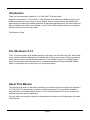
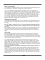
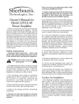
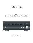
Important Safety Precautions and Explanation of Symbols
!
The exclamation point within an equilateral triangle is intended to alert the user to the presence of
important installation, operation, and service instructions in this manual.
The lightning flash with arrowhead symbol within an equilateral triangle is intended to alert the user
to the presence of uninsulated dangerous voltages within the enclosure that may be of sufficient
magnitude to constitute a risk of electrical shock to the user.
Please read this Installation and Operation Manual thoroughly before attempting to install, configure,
or operate the Sherbourn C-12. After successful installation and configuration of the C-12, be sure to
retain this manual in a safe place for future reference.
Safety is a key component to a long lasting and trouble free installation. Please read and follow all
instructions and heed all warnings on the C-12 and in this manual. The vast majority of the subsequent
safety precautions are common sense. If you are not comfortable with the installation of audio/video
entertainment equipment, you should seek the services of a qualified installation professional or call us
for help.
!
WARNING: To REDUCE the risk of fire or electric shock, do not use the
C-12 near water or in wet locations, do not expose it to rain or moisture, DO
NOT EXPOSE IT TO DRIPPING OR SPLASHING FROM OTHER SOURCES, AND ENSURE THAT
NO OBJECTS FILLED WITH LIQUIDS (SUCH AS VASES) ARE PLACED ON IT. Doing so may
result in damage to the C-12 and the risk of electric shock, which may result
in bodily injury or death.
WARNING: To reduce the risk of electric shock, do not remove the cover
from the C-12 EXCEPT TO MAKE CONFIGURATION CHANGES AS DIRECTED IN THIS
MANUAL.
!
The Sherbourn C-12 is a cooling device and, as such, is intended to be installed in locations above
equipment that generates heat. The Sherbourn C-12 may be configured to exhaust hot air in several
different directions (depending on the configuration chosen), and to operate in several different modes.
Do not install the C-12 in locations where the flow of air, as configured per the instructions in the
manual, is impeded or blocked. Do not block vents or exhaust openings in the C-12 except as directed
in this manual to implement the chosen configuration. Improper configuration of the C-12, or blocking
of the vents or air-flow openings of the C-12, may result in improper or insufficient operation of the
C-12. Doing so may result in causing either the C-12 or the equipment it services to overheat, which
may result in the risk of fire, personal injury, or equipment damage.
Always install your Sherbourn C-12 according to the manufacturer’s instructions and only use
attachments or accessories specified by the manufacturer.
Connect the Sherbourn C-12 only to an AC power adapter intended for use with the C-12, and
designed for the correct line voltage in your area. Only connect the Sherbourn C-12 AC power adapter
to an electrical outlet or extension cord of appropriate type and rating.
Protect the AC power adapter and power cables from being pinched, walked on, or otherwise
damaged. Be especially careful where the power cable exits the AC power adapter and enters the
C-12 unit.
DO NOT defeat the safety purpose of a grounding or polarized plug by removing ground pins or using
unsafe adapters. A polarized plug has two blades - one wider than the other. A grounding plug has a
third ground prong in addition to the two main conductors. The wide blade or third groundling prong is
provided for your safety. If the provided plug does not fit your outlet, consult an electrician to replace
your obsolete outlet. If you replace the C-12 power cord or AC adapter, use only a cord of similar type
and equal or greater current rating, and only an AC adapter provided by Sherbourn for the C-12
The power adapter for the Sherbourn C-12 should be unplugged from the outlet during severe
electrical storms, or when unused for a long period of time.
The C-12 should only be cleaned as directed in the Installation and Operation Manual. Avoid spraying
liquids directly onto the C-12 and NEVER spray liquids into the vents. Care should be taken so that
small objects do not fall into the inside of the C-12.
!
You should seek service for your C-12 by qualified service personnel if any of the following occur:
1. Objects or liquid have fallen or spilled into the vents.
2. The C-12 has been exposed to rain.
3. The C-12 exhibits a marked change in performance.
4. The C-12 has been dropped, or its enclosure or chassis is damaged.
You should replace the C-12 AC adapter if it has been damaged or exposed to water or other liquids.
NOTE: TO COMPLETELY DISCONNECT THE C-12 FROM THE AC POWER MAINS, DISCONNECT
THE AC POWER ADAPTER FROM THE AC RECEPTACLE.
NOTE: THE C-12’s AC POWER ADAPTER AND CABLE MUST REMAIN READILY ACCESSIBLE
AT ALL TIMES.
CAUTION
CAUTION: TO REDUCE THE RISK
OF ELECTRICAL SHOCK, DO
NOT REMOVE COVER. NO USER
SERVICEABLE PARTS INSIDE.
REFER SERVICING TO QUALIFIED
SERVICE PERSONNEL.
C-12
Flex-Rack™ Cooling System
Contents
Important Safety Precautions and Explanation of Symbols
Introduction..................................................................................................2
The Sherbourn C-12....................................................................................2
About This Manual.......................................................................................2
Mechanical and Environmental...................................................................3
Installation and Configuration......................................................................4
Mechanical Configuration............................................................................6
Performance Specifications.........................................................................9
Features....................................................................................................10
Operation...................................................................................................11
Periodic Maintenance................................................................................12
Troubleshooting.........................................................................................13
Sherbourn Technologies, LLC Ten-Year Limited Warranty........................14
Notes.........................................................................................................15
Page 1
Introduction
Thank you for choosing the Sherbourn C-12 Flex-Rack™ Cooling System.
Sherbourn’s innovative C-12 Flex-Rack™ Cooling System is an efficient and flexible solution to the
problem of excessive heat in a rack or built-in system. Heat is a major threat to the reliability and
performance of modern home theater hardware. All equipment generates heat, and many racks and
other installations have little or no ventilation, so the C-12 is all that stands between your equipment
and poor performance or an early death.
The Sherbourn Team
The Sherbourn C-12
The C-12’s three whisper quiet variable speed fans can move over 100 cubic feet of air, and it offers
a wide variety of options enabling you to customize the air flow to your needs (including an external
exhaust duct). Some of the features that make the C-12 so flexible include a low voltage trigger, a
built-in thermal and/or external pigtail sensor, a variable temperature activation threshold, and the
ability to synchronize two or more units to run at the same speed.
About This Manual
This manual will provide you with all the information you need to install and configure the Sherbourn
C-12 Flex-Rack™ Cooling System to achieve its optimum potential. The manual also includes a
brief summary of the features offered by the C-12 and a short description of how the controls work
and how to perform common operations.
You may wish to record serial numbers or other purchase information on the Notes page at the back
of this manual.
Page 2
Mechanical and Environmental
SHERBOURN
C-12
REAR
FOAM
PLUGS
SIDE
TOP
cover plate
9”
TOP & BOTTOM
(external)
8.5”
16.7”
C12 body
FRONT
(front panel removed)
2.5” 3.25”
IN-ON
OUT-AUTO
front panel
FRONT
3.5”
(external)
19”
0.1825”
Dimensions: 16.7” wide x 3.25” high x 9” deep (includes feet, foam plugs, no rack ears)
Weight: 10 lbs / 4.5 kg (unboxed); 11 lbs / 5 kg (boxed)
Rack mountable: Yes.
Power requirements:
115 VAC or 230 VAC +/- 10% @ 50 / 60 Hz (with appropriate AC power module)
Power consumption: approximately 10 watts (at high speed)
Page 3
Installation and Configuration
How the Sherbourn C-12 operates is determined both by switch settings and by mechanical
reconfiguration of parts of the device. Read and follow the instructions carefully. Improper or
incomplete configuration may result in unusual or unexpected behavior.
In general, the electrical configuration and switch settings determine when and if the C-12 fans will
operate (and at what speed), while the mechanical configuration determines the direction of air flow
through the unit when the fans are active.
Note: The Trigger In connector on the C-12 is a switched connector. Connecting a cable to
this input operates a switch inside the C-12, so plugging in a cable that is not connected
to an appropriate device at the other end may result in improper operation of the C-12. The
Trigger In connection also serves different purposes depending on how the Trigger Mode
switch is set.
Note: The Trigger Out connector carries different signal levels depending on how the Trigger
Mode switch is set. Specifically, when the Trigger Mode switch is in the Sync position, the
Trigger Out should NOT be used to trigger “ordinary” 12 V triggered devices.
Front panel Power Switch (On/Auto; on the left side of the front panel)
This is a mechanical push button switch, which toggles between settings each time it is pressed, so
it retains its setting when the C-12 is powered off.
When the front panel switch is in the On position (in), the C-12 fans will run at full speed whenever
mains power is applied to the C-12, regardless of the temperature or other settings or connections.
When the front panel switch is in the Auto position (out), the operation of the C-12 is controlled by
the Trigger Mode switch, trigger connections, and temperature sensors.
Front panel LED (blue)
The front panel LED is located just above the front panel Power switch. This LED will light blue when
power is applied to the fans (it is not a “power LED” and will not be lit if mains power is present, but
the C-12 fans are off because their temperature trigger threshold has not been exceeded).
Fan Auto-On Temperature (knob on rear panel)
This knob sets the temperature at which the C-12 fans switch on when in Auto mode. The
temperature range is from approximately 90 degrees to 104 degrees Fahrenheit
(about 32 to 40 degrees Celsius). The C-12’s fans will start running at a slow speed (and very
quietly) when this temperature is exceeded, and will run faster as the temperature increases. Once
the temperature exceeds this threshold by about fifteen degrees, the fans will be running at full
speed and maximum air flow capacity. The fans will run only as fast as needed to maintain the
desired temperature.
Temperature Sensor connector (1/8” jack on rear panel)
The C-12 has an internal temperature sensor mounted on the bottom of the chassis. The
Temperature Sensor jack on the rear panel allows for connection of an optional magnetically
mounted remote sensor. When the external sensor is plugged in, the internal sensor is completely
overridden. To ensure proper operation, use only the appropriate Sherbourn supplied external
sensor.
Page 4
Basic Auto operation
In this mode the front panel Power switch is set to the Auto position, the Trigger Mode switch is set
to the 12VDC position, and nothing is plugged into the Trigger In connector.
The C-12 is controlled by the temperature at the temperature sensor. (If the remote sensor is
attached, then this is the temperature at that location; if no remote sensor is attached, then it is the
temperature at the bottom panel of the C-12 unit. When the remote sensor is attached, the internal
sensor is disabled and ignored.) When the temperature at the sensor reaches the value set by
the Fan Auto-On Temperature knob, the fans will start at slow speed. If the temperature continues
to rise, the fans will speed up until they reach maximum speed. (The end result is that the fans
will run just fast enough to keep your cabinet at or slightly above the set temperature. When the
temperature is below the set temperature, the fans will not run.)
Triggered Auto operation
In this mode the front panel Power switch is set to the Auto position, the Trigger Mode switch is set
to the 12VDC position, and a trigger cable (from some other device) is plugged into the Trigger In
connector.
Note: The Trigger In connector on the C-12 is a switched connector. If you plug a cable into
the Trigger In connector and don’t connect it to anything, the C-12 will NOT operate in Auto
mode at all.
When the trigger input is high (+12 VDC), the C-12 operates exactly as it does in Basic Auto mode
(the fans start running when the temperature at the sensor exceeds the threshold temperature
set by the Fan Auto-On Temperature control). When the trigger input is low, the C-12 fans do not
operate.
Sync mode
Sync mode allows the operation of multiple C-12 units to be controlled by a single “master unit”.
One unit is designated as the “master” and a second (or more) units as “slaves”. The fans in all
slave units will switch on at the same time and run at the same speed as those in the master unit. All
activity will be controlled by the temperature sensor and temperature threshold setting of the master
unit. (All sensors in slave units will be ignored.)
In this mode, the front panel Power switches in all master and slave units are set to the Auto
position, and the Trigger Mode switches are set to the Sync position. A trigger cable is connected
from the Trigger Out of the master unit to the Trigger In of the slave (or first slave). If there are
additional slave units, then a trigger cable is connected from the Trigger Out of the first slave to the
Trigger In of the second slave, and so on; this is repeated until all slaves are connected. (All slaves
must be set to Auto and to Sync mode).
Note: In Sync mode there should NOT be anything plugged into the Trigger In connector of
the master unit.
In this mode, ALL C-12 units are controlled by the temperature at the temperature sensor of the
master unit. (If the remote sensor is attached, then this is the temperature at that location; if no
remote sensor is attached, then it is the temperature at the bottom panel of the C-12 unit.) When the
temperature at the sensor reaches the value set by the Fan Auto-On Temperature knob, the fans
will start at slow speed. If the temperature continues to rise, the fans will speed up until they reach
maximum speed.
Page 5
Mechanical Configuration
The direction of air flow in the C-12 is determined by the mechanical configuration of the unit itself.
The parts involved in the mechanical configuration of the C-12 are:
• Top and bottom plates - The C-12 is always operated with both top and bottom plates in place.
The top plate is removed to facilitate installing the foam block or air filter behind the front panel.
• Cover plate - The cover plate (metal) is used to cover the top or bottom vents to force air
flow in the proper direction. One cover plate is supplied with the C-12, and it is not used in all
configurations (be sure to retain the cover plate and screws in a safe place when not in use).
• Fan assembly - The fans inside the C-12 are mounted on a movable carriage which allows them
to be positioned against either the top or bottom of the case. Fans are moved by loosening the
four large screws on the sides (two on each side), repositioning the fan assembly, and
re-tightening the screws.
• Filter and Foam Block - The C-12 is supplied with both a foam filter and a dense foam block,
both of which fit behind the front panel vents. The filter is used when air flow through the front
panel is desired; the foam block is used to prevent air flow through the front panel when it is
not desired. Only one is used at once (be sure to retain the other in a safe place). To configure
these, remove the top plate and insert whichever one is required, against the front panel,
sliding it behind the long screws protruding from the bottom plate. Then replace the top plate
by inserting the front edge first (tilt the plate and insert it so the long protruding screws “pin” the
filter or foam block against the front panel rather than impaling it).
• Rear plugs - The rear plugs are foam cylinders used to block the rear vents (2) when air flow
from the rear is not configured. These plugs are dense foam cylinders, and are inserted by
squeezing them and pressing them approximately halfway into the two holes in the rear panel
(a slight twisting motion will help).
• Rear exhaust hose - When air flow from the rear exhaust vents is configured, lengths of
“standard 1-1/2” pool skimmer hose” are inserted into the rear vents (after removing and
retaining the plugs). The hose should not include end fittings of any sort; the spiral hose should
be “screwed” directly into the rear panel about two turns.
Front Exhaust (bottom entry)
•
•
•
•
Ensure that the filter (not the foam block) is installed behind the front grill
Ensure that the cover plate covers the vents in the top plate
Ensure that both rear plugs are firmly inserted
Ensure that the fan assembly is in the lower position (against the bottom plate of the C-12)
Rear Exhaust (bottom entry)
•
•
•
•
•
Ensure that the foam block (not the filter) is installed behind the front grill
Ensure that the cover plate covers the vents in the top plate
Ensure that both rear plugs are removed
Ensure that exhaust hose is firmly inserted into the rear vents
Ensure that the fan assembly is in the lower position (against the bottom plate of the C-12)
Note: The maximum air flow rate of the C-12 will be somewhat reduced with this option,
and will depend on the overall length of vent hose used. Using short hose runs, with as few
bends as possible, will help to maximize air flow and so maximize cooling.
Page 6
FRONT
FILTER
or
FOAM
BLOCK
COVER PLATE (top position)
TOP PLATE
FAN
ASSEMBLY
REAR
PLUGS
BOTTOM PLATE
COVER PLATE (bottom position)
COVER PLATE (top position)
FRONT EXHAUST
FAN
ASSEMBLY
FILTER
COVER PLATE (top position)
REAR EXHAUST
FAN
ASSEMBLY
AIR
HOSE
x2
FOAM
BLOCK
TOP EXHAUST
(front entry)
FAN
ASSEMBLY
REAR
PLUGS
FILTER
COVER PLATE (bottom position)
TOP EXHAUST
(bottom entry)
FAN
ASSEMBLY
REAR
PLUGS
FOAM
BLOCK
Page 7
Top Exhaust (front entry)
•
•
•
•
Ensure that the filter (not the foam block) is installed behind the front grill
Ensure that the cover plate covers the vents in the bottom plate
Ensure that both rear plugs are firmly inserted
Ensure that the fan assembly is in the upper position (against the top plate of the C-12)
Top Exhaust (bottom entry)
•
•
•
•
Ensure that the foam block (not the filter) is installed behind the front grill
Ensure that the cover plate is completely removed
Ensure that both rear plugs are firmly inserted
Ensure that the fan assembly is in the upper position (against the top plate of the C-12)
Page 8
Performance Specifications
Air-flow capacity:
>100 cfm; direct outlet; variable
(maximum airflow will be reduced if long exhaust ducts are used)
Cooling modes (manually selected):
•
•
•
•
Bottom Entry - Front Exhaust
Bottom Entry - Rear Exhaust (can optionally be ducted using 1-1/2” hose x 2)
Front Entry - Top Exhaust
Bottom Entry - Top Exhaust
Auto-On temperature:
•
Variable; from approximately 90 degrees Fahrenheit to 104 degrees Fahrenheit
(about 32 to 40 degrees Celsius)
Power modes:
•
•
•
•
Always on
Auto-on (by temperature)
Auto-on (by temperature) when triggered
Sync mode (slave to another unit)
Page 9
Features
The Sherbourn C-12 Flex Rack™Cooling System offers an effective and flexible cooling solution for
rack mounted equipment. Some of the features of the C-12 include:
•
•
•
•
•
•
•
•
•
•
•
Uses three high-capacity whisper-quiet 4.75 inch fans
Front panel Power switch and blue LED indicator light
Can be mechanically configured for front exhaust with bottom entry, top exhaust with front entry,
top exhaust with bottom entry, or rear exhaust with bottom entry
Front panel intake includes air filter
Offers two exhaust ports and (optional) exhaust hose for maximum flexibility
Includes embedded thermal sensor and (optional) remote sensor
Rear panel input for remote sensor
Optional synchronization of fan speeds between multiple units
12-volt trigger input
Variable starting temperature (95 to 104 degrees Fahrenheit; 32 to 40 degrees Celsius))
Rack mount front panel included (removable)
You can find more information about the Sherbourn C-12 Flex Rack™Cooling System on our Web
site at http://www.sherbourn.com
Page 10
Operation
The Sherbourn C-12 is normally configured to operate automatically.
In normal operation, the C-12 fans will not operate until the configured Starting Temperature has
been exceeded (at the sensor). At this point, the C-12’s fans will start operating at minimum speed;
fan speed will gradually increase as the temperature rises above the starting temperature.
(In situations where little air flow is needed, the fans will operate at the minimum speed necessary to
maintain temperature, ensuring minimum noise.)
The front panel switch allows the C-12 to be manually run with the fans at full. This mode is typically
used only for testing purposes.
Page 11
Periodic Maintenance
The Sherbourn C-12 requires very little periodic maintenance.
Cleaning the C-12 air filter
The interior of the C-12 (and especially the air filter) may become dusty (or accumulate lint and
other debris) with normal operation. If this occurs, periodically disconnect the power, remove the
top cover, and vacuum out any loose debris and dust that has accumulated (be careful to avoid
damaging the interior circuit boards and wiring). The filter should be vacuumed periodically, and may
be carefully washed and rinsed if necessary.
Page 12
Troubleshooting
If problems occur, the first step should be to verify that the Sherbourn C-12 is attached to an
appropriate (Sherbourn supplied) AC adapter (“power brick”), and that the AC adapter used is rated
for the local AC line voltage.
Note: If a cable is connected to the Trigger Input of the C-12, but not connected to a
triggering device, the C-12 will not act as expected with the Trigger switch in either position.
DO NOT insert a cable into the Trigger In connector unless the other end is connected to an
active device.
Problem: No air flow (fans sound like they are running)
•
Verify that the C-12 is configured correctly (mechanical configuration)
Problem: Fans never come on - even at high temperatures
•
•
•
•
Verify that, if a remote temperature sensor is used, it is in the warmest spot in the cabinet
Verify that the Fan Auto-On temperature control is set to the desired temperature.
Verify that ONLY a remote temperature sensor is plugged into the Temp Sensor connector
(plugging a trigger cable or other cable into this connector will result unpredictable behavior and
possible damage to the C-12)
Verify that, if a remote device is expected to trigger the C-12, the trigger signal is active and the
Trigger Mode switch in in the 12VDC position.
Problem: Fans run when they shouldn’t
•
•
•
•
Verify that the Fan Auto-On temperature control is set to the desired temperature.
Verify that ONLY a remote temperature sensor is plugged into the Temp Sensor connector
(plugging a trigger cable or other cable into this connector will result unpredictable behavior and
possible damage to the C-12)
Verify that, if a remote device is expected to trigger the C-12, the trigger signal is active and the
Trigger Mode switch in in the 12VDC position.
Verify that, if the C-12 is being run in Sync mode, the C-12 unit connected to its Trigger In is
also in Sync mode (and that ONLY another Sherbourn C-12 unit in Sync mode is connected to
its Trigger In.)
Problem: Fans come on, but air flow seems weak
•
•
•
Verify that the C-12 is configured correctly (mechanical configuration)
Check if the filter needs cleaning
If exhaust hoses are used, verify that they are clear of obstruction (and not too long)
Problem: Fans ONLY run at full speed
•
Verify that, if a trigger input is used, and the C-12 is not a slave unit to another C-12, the Trigger
Mode switch is not in the Sync position
Page 13
Sherbourn Technologies, LLC Ten-Year Limited Warranty
What does this warranty cover? Sherbourn Technologies, LLC (“Sherbourn”) warrants its
products against defects in materials and workmanship. This warranty is subject to revision at any
time.
How long does this coverage last? This warranty commences on the date of retail purchase
by the original retail purchaser and runs for a period of ten (10) years thereafter, with the following
exceptions: (1) receivers (including the SR-8100, SR-8200, and SR-120), preamp/processors
(including the PT-7030, PT-720C4, and PT-7020), preamplifiers (including the PRE-1), and the
CD-1 CD Player (with the exception of the slot load CD engine) are covered by this warranty for
five (5) years from the date of retail purchase by the original purchaser; and (2) electromechanical
components, including the slot load CD engine on the CD-1 CD Player, and all fans (including
the C-12 Cooling Unit), are covered by this warranty for three (3) years from the date of retail
purchase by the original retail purchaser. This warranty is transferrable, upon written notification
to Sherbourn, to any person that owns the warranted product, however, if ownership is transferred,
the Term shall be no longer than five (5) years from the date of purchase by the original purchaser.
Sherbourn warrants any replacement product or part furnished hereunder against defects in
materials and workmanship for the longer of the following: (i) the amount of time remaining under
the original warranty, or (ii) 120 days from your receipt of the repaired or replaced product. The
duration described in the previous 3 sentences is hereinafter referred to as the “Term”. TO THE
FULLEST EXTENT PERMITTED BY LAW, ALL IMPLIED WARRANTIES RELATED TO THE
ORIGINAL PRODUCT AND ANY REPLACEMENT PRODUCT OR PARTS (INCLUDING IMPLIED
WARRANTIES OF MERCHANTABILITY AND FITNESS FOR A PARTICULAR PURPOSE) ARE
EXPRESSLY LIMITED TO THE TERM OF THIS LIMITED WARRANTY. SOME STATES DO
NOT ALLOW LIMITATIONS ON HOW LONG AN IMPLIED WARRANTY LASTS, SO THE ABOVE
LIMITATION MAY NOT APPLY TO YOU. A claim under this warranty must be made by you within
the Term. A claim shall not be valid (and Sherbourn has no obligation related to the claim) if it is not
made within the Term and if it is not made in strict compliance with the requirements of the “How do
you get service?” section.
What will Sherbourn do? Sherbourn will, at its option, either: (i) repair the product, or (ii) replace
the product with a new consumer product which is identical or reasonably equivalent to the product.
Sherbourn may provide you with a refund of the actual purchase price of the product in the event
(i) Sherbourn is unable to provide replacement and repair is not commercially practicable or cannot
be timely made, or (ii) you agree to accept a refund in lieu of other remedies hereunder. When
a product or part is repaired or replaced, any replacement item becomes your property and the
replaced item becomes Sherbourn’s property. When a refund is given, the product for which the
refund is provided must be returned to Sherbourn and becomes Sherbourn’s property.
What is not covered by this warranty? This warranty does not apply: (i) to damage caused by
use with non-Sherbourn products, where the non-Sherbourn product is the cause of the damage;
(ii) to damage caused by service or maintenance performed by anyone who is not a representative
of Sherbourn; (iii) to damage caused by accident, abuse, misuse, flood, fire, earthquake or other
external causes; (iv) to a product or part that has been modified after its retail purchase, where
the modification caused or contributed to the damage; (v) to consumable parts, such as batteries;
(vi) normal wear tear; or (vii) if any Sherbourn serial number has been removed or defaced and
Sherbourn cannot otherwise confirm that you are the original retail purchaser or authorized
transferee. SHERBOURN SHALL NOT BE LIABLE FOR ANY INCIDENTAL OR CONSEQUENTIAL
Page 14
DAMAGES ARISING FROM OR RELATED TO ANY DEFECTS IN OR DAMAGES TO ITS
PRODUCTS. SOME STATES DO NOT ALLOW THE EXCLUSION OR LIMITATION OF
INCIDENTAL OR CONSEQUENTIAL DAMAGES, SO THE ABOVE LIMITATION OR EXCLUSION
MAY NOT APPLY.
How do you get service? In order to make a claim under the warranty, you must:
1.
Call a customer service representative (“CSR”) of Sherbourn at (1-877-EMO-TECH /
1-877-366-8324). Provide the CSR with a description of your problem and the serial number of the
product for which the warranty claim is being made.
2.
The CSR will provide you with a returned material authorization number (“RMA”).
3.
Ship the product to Sherbourn at the following address, with the RMA written in large,
bold letters on the outside of the box, and with the letters “RMA” written before the number. Parcels
arriving without a RMA number on the outside of the box will be refused.
Sherbourn Technologies, LLC
Attn: Repair Department
135 Southeast Parkway Court
Franklin, TN 37064
How does state law apply? This warranty gives you specific legal rights, and you may also
have other rights which vary from state to state. CERTAIN STATES HAVE ENACTED LAWS
WHICH PRECLUDE THE WAIVER OF CONSEQUENTIAL AND INCIDENTAL DAMAGES AND/
OR PRECLUDE THE WAIVER/LIMITATION OF IMPLIED WARRANTIES. TO THE EXTENT
YOUR STATE HAS ENACTED A LAW WHICH PROHIBITS SUCH A WAIVER/LIMITATION, ALL
SUCH WAIVERS/LIMITATIONS CONTAINED IN THIS WARRANTY ARE INAPPLICABLE TO YOU.
CERTAIN STATES HAVE ENACTED LAWS WHICH REQUIRE THE DURATION OF A WARRANTY
TO BE EXTENDED (INCLUDING BUT NOT LIMITED TO DURING PERIODS OF REPAIR). TO
THE EXTENT YOUR STATE HAS ENACTED A LAW OF THIS NATURE, THEN THE DURATION
OF THIS WARRANTY WILL BE EXTENDED AS REQUIRED BY APPLICABLE LAW.
Notes
All information contained in this manual is accurate to the best of our knowledge at the
time of publication. In keeping with our policy of ongoing product improvement, we reserve the right to
make changes to the design and features of our products without prior notice.
User Manual Revision 2
Page 15
May 2013