1
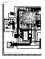
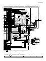
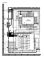
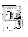
CD-K491W
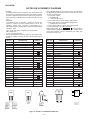
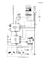
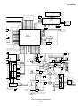
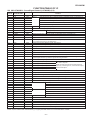
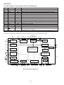
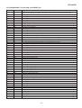
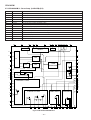
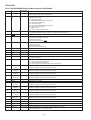
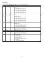
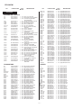
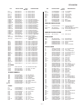
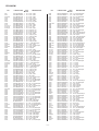
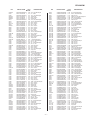
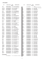
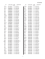
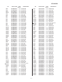
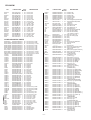
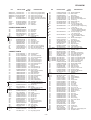
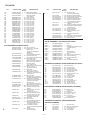
ICA18 VHiZR38600/-1: DOLBY AC-3/5.1CH MPEG2 AUDIO DECORDER (ZR38600 ) (2/2)
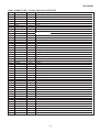
Pin No.
Terminal Name Input/Output
54
SDD
Output
55
VCC
—
56*
GPIO2
Input/Output
General-purpose I/O pin
57*
GPIO1
Input/Output
General-purpose I/O pin
58*
GPIO0
Input/Output
59
VCC
60
GND
61
SPFRX
62
63*
64
—
—
Function
Data output for serial ports B, C and D
Used to connect a power supply of +3.3V ±5%
General-purpose I/O pin
Used to connect a power supply of +3.3V ±5%
Ground pin
Input
Digital audio interface input terminal
P/M
Input
Parallel port/memory port mode setting pin
XTO
Output
Crystal oscillator input/output terminal
XTI
Input
Crystal oscillator input/output terminal
65
GND
66
SCKIN
—
67
VCC
—
Used to connect a power supply of +3.3V ±5%
68
GNDA
—
Ground pin
69
FLTCAP
70
VCCA
71
GND
72*
CLKOUT
73*
D19
Input/Output
Data bus
74*
D18
Input/Output
Data bus
75*
A17
Output
Address bus. The address bus is always active.
76*
A18
Output
Address bus. The address bus is always active.
77*
A19
Output
Address bus. The address bus is always active.
Input/Output
Input
Ground pin
Group B serial port clock input/output.
Internal PLL circuit terminal for connecting a capacitor
—
Used to connect a power supply of +3.3V ±5%
—
Ground pin
Output
78
GND
—
79
SDC
Output
Ground pin
80
SDB
Output
81
VCC
—
82
RESET
Input
83
SDA
Input
84
VCC
—
85
SDE
Input
Data input for serial ports A, E and F
86
TCK
Input
ICE interface clock (JTAG)
87
SCK
Input
Serial host interfase: Clockinput (SPI)
88
TDI
Input
ICE interfase data input (JTAG)
89
SI
Input
Serial host interfase: Serialdata input (SPI)
90
GND
—
91
SCKA
Input/Output
Group A serial port clock input /output
92
WSA/FSA
Input/Output
Group A serial port (for input) word selection or frame synchronous input/output
93
VCC
—
94
SDF
Input
95
WSB
Input/Output
Data output for serial ports B, C and D
Data output for serial ports B, C and D
Used to connect a power supply of +3.3V ±5%
Reset input. Resetting is executed from the specified status and address by the reset signal.
Data input for serial ports A, E and F
Used to connect a power supply of +3.3V ±5%
Ground pin
Used to connect a power supply of +3.3V ±5%
Data input for serial ports A, E and F
Word selection input/output for the group B serialport
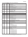
96*
D17
Input/Output
Data bus
97
SCKB
Input/Output
Grop B serial port clock input/output
98*
D16
Input/Output
99
SPFTX/SDG
100*
D15
Output
Input/Output
Data bus
Serial port G data output digital audio interface output terminal
Data bus
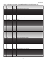
In this unit, the terminal with asterisk mark (*) is (open) terminal which is not connected to the outside.
– 66 –