1
4/15
BH20021, Rev 16
Brake Actuator
REV.
ECN #
DATE
DFTM
A
3808
5/8/2008
BVDP
B
4485
11/4/2010
BVDP
7
8
B
27
Page 1
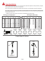
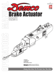
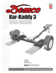
DEMCO MODEL DA20 ACTUATOR
Model DA20 is a heavy duty surge brake actuator for trailers with two or four wheels.
When brakes are applied on the towing vehicle, forward inertia of trailer toward towing vehicle applies brakes on trailer in direct relation to manner brakes are applied
on towing vehicle. Brake towing vehicle hard and brakes on trailer are applied hard.
Master cylinder push rod spring assembly protects system from hydraulic pressure
overload.
WARNING: To Prevent Serious Injury or Death
• Review following instructions before installation and use of hydraulic brake
actuator.
• Dealers or distributors must review these instructions with ultimate user.
• Failure to follow these instructions, or failure to properly maintain braking
system after installation, can result in loss of braking action.
WARRANTY POLICY & REGISTRATION
Go online to www.demco-products.com to review Demco warranty policies and register your Demco product.
Table of Contents
General information.............................................................................................................. 2
Warranty Policy & Registration............................................................................................. 2
Safety, Signal Words and Equipment Safety Guidelines...................................................... 3
Safety Sign Locations & Safety Sign Care........................................................................... 4
Before Operation.................................................................................................................. 5
During Operation.................................................................................................................. 5
Following Operation............................................................................................................. 6
Highway and Transport Operations...................................................................................... 6
Performing Maintenance...................................................................................................... 7
Bolt Torque........................................................................................................................... 8
Coupler Repair Kit Options.................................................................................................. 8
Bolt/Weight Rating Warning................................................................................................. 9
Weld On Instructions............................................................................................................ 9
Free Backing Solenoid Kits.................................................................................................. 9
Actuator Breakdown and Parts List..................................................................................... 10
Optional Outer Case & Hitch Configurations....................................................................... 11
eZ-Latch Coupler Operations.............................................................................................. 12
Actuator Installation and Maintenance..............................................................................13-14
Rue Ring Installation........................................................................................................... 15
All Demco actuators and brake assemblies are
compatible with DOT 3 or 4 brake fluid.
Page 2
SAFETY
TAKE NOTE! THIS SAFETY ALERT SYMBOL FOUND THROUGHOUT THIS MANUAL IS USED TO CALL
YOUR ATTENTION TO INSTRUCTIONS INVOLVING YOUR PERSONAL SAFETY AND SAFETY OF
OTHERS. FAILURE TO FOLLOW THESE INSTRUCTIONS CAN RESULT IN INJURY OR DEATH.
THIS SYMBOL MEANS
ATTENTION
BECOME ALERT
YOUR SAFETY IS INVOLVED!
SIGNAL WORDS
warning:
Note use following signal words DANGER, WARNING, and
CAUTION with safety messages. Appropriate signal word
for each has been selected using following guidelines:
Indicates a potentially hazardous situation that, if not avoided,
could result in serious injury or death, and includes hazards
that are exposed when guards are removed. It may also be
used to alert against unsafe practices.
DANGER:
caution:
Indicates an imminently hazardous situation that, if not
avoided, will result in serious injury or death. This signal
word is to be limited to most extreme situations typically for
machine components which, for functional purposes, cannot
be guarded.
Indicates a potentially hazardous situation that, if not avoided,
may result in minor or moderate injury. It may also be used
to alert against unsafe practices.
If you have questions not answered in this manual, require additional copies, or if your manual is damaged, please contact
your dealer or DEMCO, P.O. Box 189, 4010 320th Street, Boyden, IA 51234
ph: (712) 725-2311Toll Free: 1-800-543-3626 Fax: (712) 725-2380 http://www.demco-products.com
Equipment safety guidelines
Every year many accidents occur which could have been avoided by a few seconds of thought and a more careful
approach to handling equipment. You the operator, can avoid many accidents by observing and following precautions
in this section. To avoid personal injury, study the following precautions and insist those working with you, or you
yourself, follow them.
In order to provide a better view, certain illustrations in this manual may show an assembly with a safety shield removed.
However, equipment should never be operated in this condition. Keep all shields in place. If shield removal becomes
necessary for repairs, replace shield prior to use.
Replace any caution, warning, danger or instruction safety decal that is not readable or is missing. Location of such
decals is indicated in this booklet.
Do not attempt to operate this equipment under the influence of alcohol or drugs.
Review safety instructions with all users.
Operator should be a responsible adult. Do not allow persons to operate or assemble this unit
until they have developed a thorough understanding of safety precautions and how it
works.
Do not paint over, remove, or deface any safety signs or warning decals on your equipment. Observe all safety signs
and practice instructions on them.
Never exceed limits of a piece of machinery. If its ability to do a job, or to do so safely is in question-don’t try it.
Remember
Your best assurance against accidents is a careful and responsible operator. If there is any portion of this manual
or function you do not understand, contact your local authorized dealer or manufacturer. Page 3
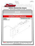
SAFETY sign locations
Types of safety sign and locations on equipment are shown in illustration below. Good safety requires that
you familiarize yourself with various safety signs, type of warning, and area or particular function related to
that area, that requires your SAFETY AWARENESS.
BRAKES ON BRAKES OFF
DO NOT TOW TOWABLE
BH21003
Safety sign care
• Keep safety signs clean and legible at all times.
• Replace safety signs that are missing or have become illegible.
• Replacement parts that displayed a safety sign should also display safety sign.
• Safety signs are available from your distributor, dealer parts department, or factory.
How to install safety signs:
• Be sure that installation area is clean and dry.
• Decide on exact position before you remove backing paper.
• Remove smallest portion of split backing paper.
• Align decal over specified area and carefully press small portion with exposed sticky backing in place.
• Slowly peel back remaining paper and carefully smooth remaining portion of decal into place.
• Small air pockets can be pierced with a pin and smoothed out using piece of decal backing paper.
Page 4
Before operation:
• Carefully study and understand this manual.
• Always wear protective clothing and substantial shoes.
• Give equipment a visual inspection for any loose bolts, worn parts, or cracked welds, and make necessary repairs. Follow maintenance safety instructions included in this manual.
• Be sure there are no tools lying on or in equipment.
• Do not use equipment until you are sure that area is clear, especially around children and animals.
• Don’t hurry learning process or take equipment for granted. Ease into it and become familiar with your new equipment.
• Practice operation of your equipment and its attachments. Completely familiarize yourself and other operators with its operation before using.
• Make sure that brakes are evenly adjusted.
• Make sure tow rating on vehicle is high enough for what it is towing.
• Do not allow anyone to stand between tongue or hitch and towing vehicle when backing up to equipment.
• Securely attach to towing vehicle. Use appropriately sized hitch ball and/or hitch pin with a mechanical retainer and attach safety chains.
• Criss cross chains under tongue and secure to draw bar cage, mounting loops, or bumper frame.
During operation
•
•
•
SAFETY CHAINS OR CABLES If equipment is going to be transported on a public highway, safety chains or cables should be obtained and installed. Always follow state and local regulations regarding safety chains
or cables and auxiliary lighting when towing equipment on a public highway. Be sure to check with local law enforcement agencies for your own particular regulations. Only safety chains or cables (not an elastic or nylon/plastic tow straps) should be used to retain connection between towing and towed equipment in event of separation of primary attaching system.
Install safety chains by criss crossing chains under tongue and secure to draw bar cage, mounting loops, or bumper frame.
When attaching the emergency cable Allow adequate slack to keep from activating brakes due to
interference from parts of the coupler or other attachments on the towing vehicle. Each vehicle tongue configuration is different and therefore each should be handled individually to keep the routing free
from entanglements and securely attached to perform as designed in case of emergency disconnection from the towing vehicle.
• Beware of bystanders, PARTICULARLY CHILDREN! Always look around to make sure it is safe to start engine of towing vehicle or move equipment. This is particularly important with higher noise levels, as you may not hear people shouting.
• NO PASSENGERS ALLOWED- Do not carry passengers anywhere on or in equipment.
• Do not clean, lubricate, or adjust your equipment while it is moving.
• When halting operation, even periodically, set towing vehicles parking brake, shut off engine, and remove the ignition key.
• Be extra careful when using on inclines.
• MANEUVER TOWING UNIT AT SAFE SPEEDS.
• Avoid loose gravel, rocks, and holes, they can be dangerous for equipment operation or movement.
• Allow for overall length when making turns.
• Keep all bystanders and pets clear of work area.
• Operate towing vehicle from operators seat only.
• Never leave running equipment attachments unattended.
• As a precaution, always recheck hardware on equipment following every 100 hours or 50 miles. Correct all problems. Follow maintenance safety procedures.
Page 5
Following operation
• Following operation, or when unhitching, stop towing vehicle, set brakes, shut off the engine and remove
ignition key.
• Store unit in an area away from human activity.
• Do not permit children to play on or around stored unit.
• Make sure all parked units are on a hard, level surface and engage all safety devices.
• Wheel chocks may be needed to prevent unit from rolling.
Highway and transport operations
• Adopt safe driving practices:
- Always drive at a safe speed relative to local conditions and ensure that your speed is low enough for an
emergency stop.
- Reduce speed prior to turns to avoid risk of overturning.
- Always keep towing vehicle in gear to provide engine braking when going downhill. Do not coast.
- Do not drink and drive!
• Comply with state and local laws governing highway safety on public roads.
• Use approved accessory lighting, flags and necessary warning devices to protect operators of other vehicles on highway during transport. Various safety lights and devices are available from your dealer.
• Local laws should be checked for all highway lighting and marking requirements.
• Plan your route to avoid heavy traffic.
• Be a safe and courteous driver. Always yield to oncoming traffic in all situations, including narrow bridges, intersections, etc.
• Be observant of bridge loading ratings. Do not cross bridges rated lower than the gross weight at which you
are operating.
• Watch for obstructions overhead and side to side while transporting.
• Always operate equipment in a position to provide maximum visibility at all times. Make allowances for
increased length and weight of equipment when making turns and/or stopping.
Page 6
Performing maintenance
•
Good maintenance is your responsibility. Poor maintenance is an invitation to trouble.
•
Make sure there is plenty of ventilation. Never operate engine of towing vehicle in a closed building. Exhaust fumes may cause asphyxiation.
•
Before working on this unit, stop towing vehicle, set parking brakes, shut off engine and remove ignition key.
•
Be certain all moving parts and attachments have come to a complete stop before
attempting to perform maintenance.
•
Always use safety supports and block wheels. Never use a jack to support unit.
•
Always use proper tools or equipment for job at hand.
•
Use extreme caution when making adjustments.
•
Follow torque chart in this manual when tightening bolts and nuts.
•
Openings in skin and minor cuts are susceptible to infection from brake fluid.
Without immediate medical treatment, serious infection and reactions can occur.
•
Replace all shields and guards after servicing and before moving.
•
After servicing, be sure all tools, parts and service equipment are removed.
•
Do not allow grease or oil to build up on the actuator.
•
When replacing bolts, refer to owners manual.
•
Refer to bolt torque chart for head identification marking.
•
Where replacement parts are necessary for periodic maintenance and servicing, genuine factory replacement parts must be used to restore your equipment to original specifications. Manufacturer will not claim responsibility for
use of unapproved parts or accessories and other damages as a result of their use.
•
If equipment has been altered in any way from original design, manufacturer does not accept any liability for injury or warranty.
•
A fire extinguisher and first aid kit should be kept readily accessible while performing maintenance on this equipment
Page 7
Torque Specifications
Tighten all bolts to torques specified in chart unless otherwise noted. Check tightness of bolts periodically, using bolt
chart as guide. Replace hardware with same grade bolt.
NOTE: Unless otherwise specified, high-strength Grade 5 hex bolts are used throughout assembly of equipment.
Torque figures indicated are valid for non-greased or non-oiled threads and heads unless otherwise specified. Therefore, do not grease or oil bolts or capscrews unless otherwise specified in this manual. When using locking elements,
increase torque values by 5%.
* GRADE or CLASS value for bolts and capscrews are identified by their head markings.
Bolt Torque for Metric bolts *
Bolt Torque for Standard bolts *
GRADE 2GRADE 5GRADE 8
“A” lb-ft (N.m) lb-ft (N.m) lb-ft (N.m)
1/4”
6 (8)
9 (12) 12 (16)
5/16” 10 (13) 18 (25) 25 (35)
3/8” 20 (27) 30 (40) 45 (60)
7/16” 30 (40) 50 (70) 80 (110)
1/2” 45 (60) 75 (100) 115 (155)
9/16” 70 (95) 115 (155) 165 (220)
5/8” 95 (130) 150 (200) 225 (300)
3/4” 165 (225) 290 (390) 400 (540)
7/8” 170 (230) 420 (570) 650 (880)
1”
225 (300) 630 (850) 970(1310)
GRADE-2
CLASS 8.8CLASS 9.8CLASS 10.9
“A” lb-ft (N.m) lb-ft (N.m) lb-ft (N.m)
6
9 (13)
10 (14)
13 (17)
7 15 (21)
18 (24)
21 (29)
8 23 (31)
25 (34)
31 (42)
10 45 (61)
50 (68)
61 (83)
12 78 (106)
88 (118) 106 (144)
14 125 (169) 140 (189) 170 (230)
16 194 (263) 216 (293) 263 (357)
18 268 (363)
--
--
364 (493)
20 378 (513)
--
--
515 (689)
22 516 (699)
--
--
702 (952)
24 654 (886)
--
--
890 (1206)
GRADE-8
GRADE-5
CLASS 8.8
CLASS 9.8
CLASS 10.9
8.8
9.8
10.9
A
Coupler Repair Kit Options
2 5/16” eZ-Latch Composite
Handle
0$<+$9(72
*5,1'3,172),7 %
,7(0
$
5817
5(9
(&1
'$7(
')70
$
%9'3
%
-&1
7+6732%2;
%2<'(1,2:$
7+('5$:,1*$1'$//
,1)250$7,217+(5(
21$5(7+(3523(57<2)
'(0&2
:(,*+7
92/80(
%$//&/$03
&/$03%2/7
(=/$7&+/(9(5635,1*
/(9(5+$1'/($66(0%/<
&283/(563$&(5%/2&.
ELOOYS
$3329%<
*%
'$7(
-&1
47<
'2:(/*5229('52//3,1
'$7(
6$9('%<
81/(6627+(5:,6(
63(&,),('$//',0(16,216
$5(,1,1&+(6
'(6&5,37,21
'5$:1%<
2 5/16” Ball Coupler
Repair Kit
7+,5'$1*/(
352-(&7,21
3$57
'$7(
72/(5$1&(6
; 0,10$&+,1(685)$&(
;; %5($.$//6+$53('*(6
;;; %(1'$1''5$)7
'(6&5,37,21
&283/(55(3$,5.,7
'5$:,1*12
6&$/(
5(9
%
6+((72)
Page 8
6008 eZ-Latch Repair Kit
WARNING:
To Avoid Personal Injury or Property
Damage, Observe THE Following Instructions:
The weight rating of the coupler is dependent on the correct bolts being used. You must use the
exact size, grade and number of bolts specified in the manual. Mounting hardware can be obtained
from Demco, trailer parts distributors or fastener supplier.
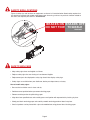
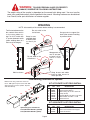
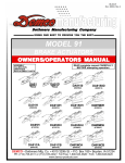
WELDING
NOTE: disassembly of the actuator before welding is recommended
Do not weld in the
circled area
Tack Actuator down on the
four corners then weld in
a criss cross pattern using 2” to 2-1/2” welds with
2” spaces between welds
(when welding down to a
flat area of the tongue)
Keep braces
and welds back
to allow access
to shock pin
hole
Use gussets to support the
back of the actuator if welding
in position shown
8
1
Keep gussets on
rear of actuator
to lower half to
avo i d c i r c l e d
area
2
7
Do not weld in the
circled area
3
6
5
4
Keep braces and welds
back to allow access to
shock pin holes
Weld as shown
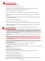
Free Backing Solenoid Kit Options
Drill the hole using a 5/32” bit. Hole location is .900” right of top left corner and .900”
down from top of master cylinder. Tap hole
with 10-32 NF tap.
30
29
32
KIT #5753 PARTS LIST FIELD INSTALL
EF. PART
R
NO.
NO.QTY.
DESCRIPTION
29 04594
- EPDM Black Tubing
30 05561
1 Solenoid Valve Bypass
31 10373
1 Brass Fitting Str. .2 HB x 10-32 NF
32 10374 2 Crimp Clamp
33 10375
1 Straight Nipple 1/8” MPT x 1/8” MPT
34 10376 1 Brass Elbow 1/8” MPT x .2 HB
35 11675-95 1 Solenoid Cover
31
33
35
34
37
32
KIT #5838 PARTS LIST FIELD INSTALL
36
EF. PART
R
NO.
NO.QTY.
DESCRIPTION
35 11675-95 1 Solenoid Cover
36 11993
1 Inline Solenoid Valve Non-Bypass
37 07283
1 10mm Flatwasher
Optional by-pass solenoid kits
5754 (FACTORY INSTALL)-(drum)
5755 (FACTORY INSTALL)-(disc)
Page 9
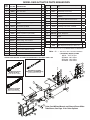
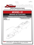
MODEL DA20 ACTUATOR PARTS BREAKDOWN
Ref
NO.
Part NO.
1
00057
Washer, .25 Spring Lock
4
20
10962 *
DA20 Slide Channel Top
1
2
00062
Nut .25nc Hex
4
21
10963 *
DA20 Slide Channel Bot
1
4
00618
Bolt, .25 Nc X 2.00 Hex Head Gr.5
4
22
10964 *
DA10 & DA20 Spacer
2
23
Inner Slide Tube, Offset Channel
(Shown)
1
Inner Slider Tube Channel Center
-
Inner Slider Tube Channel Up
-
DESCRIPTION
6
03409-95 Pin, Front Stock
1
7
03410-95 Cold Headed Clevis Pin, .625
1
8
03411-95 Cold Headed Clevis Pin, .875
2
9
10
11
12
1.25” Bore Aluminum Master Cyl. Kit
Disc
DA20 Outer Case see page 12 for
others
1
24
12396
Rue Ring Lock Cotter 5/8 Shaft
1
03534
Push rod Assy-DA20
1
25
12397
Rue Ring Lock Cotter, 7/8 Shaft
2
11724
1.25” Bore Push rod Assy
-
26
12557
Fill Plate for Master Cylinder
1
1
27
05408
Replacement Safety Cable
1
1
28
03866-95 Emergency Lever Guide
03876
Master Cylinder Cap Assembly
05849
O-Ring (Replacement)
13
05424
Washer, .313 External Tooth Lock
2
14
05679**
Brake Fitting .125 Full Flow
1
15
5783
Qty
-
05693-95 Spring, Safety Lever
05951
Emergency Lever
1
17
05961
Bolt, .313 Nc X .625 Hex Head Gr5
2
18
09153
Cork Gasket f/Master Cylinder
1
19
5650
A
Composite
Master
3808
5/8/2008Cylinder
BVDP Drum Kit
1
5672
B
REV.
ECN #
4485
DATE
DFTM
10/19/2010
2
BH21003 Replacement Towable/Not Towable
Decal
-
05687
Replacement Master Cyl. Rubber Boot
1
-
5401
Lever Replacement Kit (incl. items w/**)
-
-
5944
Slide Replacement kit (incl. items w/*)
29
1
16
SB12426 Shock, Dampener
Please order replacement parts by PART NO. COLOR and DESCRIPTION
Note: -?? = -95 Plated -97 Primed Red -35 Black
**(OPTIONAL) BRAKE FITTING
BVDP
Composite Master Cylinder Kit Disc
05679 - .125 Full Flow
SB12099 - .031 Orifice
SB12100 - .024 Orifice
SB12098 - .016 Orifice
LARGE BORE MASTER CYLINDER RECOMMENDED FOR THREE AXLE & UP
12
A
5
5945 Master Cylinder
Repair Kit (1.25 BORE disc)
5482 Master Cylinder
Repair Kit (disc)
(gasket 09153 included)
(gasket 09153 included)
DRAWN BY
ENG APPOV.
4010 320TH ST. PO BOX 189
BOYDEN, IOWA 51234
THE DRAWING AND ALL
INFORMATION THERE
ON ARE THE PROPERTY OF
DEMCO
BVDP
BVDP
PART #
1
05687
MASTER CYLINDER BOOT
2
09153
CORK GASKET F/ MASTER CYLINDER
3
10776
4
10777
5
10780
10781
DATE
11/02/09
DATE
11/02/09
UNLESS OTHERWISE
SPECIFIEDALL DIMENSIONS THIRD ANGLE
PROJECTION
ARE IN INCHES
DESCRIPTION
SNAP RING
PRIMARY CUP 1.25" BORE MASTER
CYLINDER
1.25" Alum. Piston with Seal
7
SPRING & CAP ASSEMBLY
1
1
1
1
1
1
15
5945
SCALE: 1:2
REV
_
4
B
2
SHEET 1 OF 1
27
9
24
(gasket 09153 included)
20
25
28
23
14
10
8
5398 Master Cylinder
Repair Kit (drum)
19
29
1
KIT REPAIR 1.25 BORE DISC
DRAWING. NO.
MIN. MACHINE SURFACE 250
BREAK ALL SHARP EDGES
BEND AND DRAFT
±1°
11
QTY
DESCRIPTION
TOLERANCES
.X = .060
.XX = ±.030
.XXX = ±.010
18
17
13
ITEM
6
3 16
26
6
ITEM
1
2
3
4
5
6
7
8
9
10
11
12
13
14
15
16
17
18
19
20
21
22
23
24
25
26
27
28
PART #
00057
00062
00068
00618
02772
03409-95
03410-95
03411-95
03412-97
03534
03866-95
03876
05424
05679
05693-95
05951
05961
09153
10616
10962
10963
10964
11042-97
12396
12397
12557
13730
SB12426
DESCRIP
WASHER, .25 SPRING
NUT .25NC HEX
HBOLT 0.2500-20x0.75
BOLT, .25 NC X 2.00 H
NUT, .25NC LOCK NYL
PIN, FRONT STOCK
COLD HEADED CLEVI
COLD HEADED CLEVI
DA20 OUTER CASE
PUSHROD ASSY-DA20
EMERGENCY LEVER G
MASTER CYLINDER CA
WASHER, .313 EXTERN
BRAKE FITTING .125 FU
SPRING, SAFETY LEVER
EMERGENCY LEVER
BOLT, .313 NC X .625
CORK GASKET F/ MAS
COMPOSITE MASTER
DA20 SLIDE CHANNEL
DA20 SLIDE CHANNEL
DA10 & DA20 SPACER
INNER SLIDE TUBE, OFF
RUE RING LOCK COTT
RUE RING LOCK COTT
CAP FOR MASTER CY
SAFETY CABLE F/ ACT
SHOCK, DAMPER
Outer Case Without Mounts and Channel Down Slider
Tube Shown, See Page 12DRAWN
forBYOther
Options
DATE
05/12/08 DESCRIPTION
BVDP
ENG APPOV.
22
21
*
*
4010 320TH ST. PO BOX 189
BOYDEN, IOWA 51234
Page 10
THE DRAWING AND ALL
INFORMATION THERE
ON ARE THE PROPERTY OF
DEMCO
BVDP
DATE
11/01/10
UNLESS OTHERWISE
SPECIFIEDALL DIMENSIONS THIRD ANGLE
PROJECTION
ARE IN INCHES
TOLERANCES
.X = .060
.XX = ±.030
.XXX = ±.010
MIN. MACHINE SUFACE 250
BREAK ALL SHARP EDGES
BEND AND DRAFT
±1°
ACT DA20 PRIMD
& NO MOUNT OU
8202
DRAWING. NO.
SCALE: 1:7
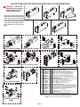
OUTER CASE OPTIONS AND AVAILABLE HITCH CONFIGURATIONS
WARNING: To Avoid Per-
33
sonal Injury or Property
Damage, Observe THE Following Instructions:
35
34
The weight rating of the coupler is
dependent on the correct bolts being
used. You must use the exact size,
grade and number of bolts specified
in the manual. Mounting hardware
can be obtained from Demco, trailer
parts distributors or fastener suppliers.
37
36
48
46
39
44
43
48
44
43
42
48
51
48
RATED AT 20000#
41
1.06
(2-5/16”)RATED AT 20000#
48
(2-5/16”)RATED AT 20000#
48
43
48
48
43
48
49
48
(2 5/16”) RATED AT 20000#
48
43
47
43
48
48
45
40
48
50
2 5/16” RATED AT 20000#
52
43
48
43
48
48
RATED AT 10000#
(2 5/16”) RATED AT 12500#
38
42
RATED AT 20000#
33.
34.
35.
36.
37.
38.
39.
40.
41.
42.
43.
44.
45.
46.
47.
48.
49.
50.
51.
52.
DA20
03412-?? 03548-?? 03884-97 07105-97 07718-97 11043-97 11051-?? 05593-?? 09557-?? 02434 03730 02587 05557-?? 11046-?? 11047-97 04051
07678-?? 12141-??
12676-??
14040-??
1
1
1
1
1
1
1
1
1
2
4
2
1
1
1
4
1
1
1
1
OPTIONS
Outer Case w/ no mount
Outer Case w/ 6 hole mount
Outer Case w/ 50° mount (primed red)
Outer Case w/ channel mount (primed red)
Outer Case w/ angle mounts (primed red)
Flat Mount Inner Slide Tube (primed red)
2-5/16” Lever Lock Coupler Slider (drop tube)
10,000 lb. Clevis
Pintle Ring (20,000 lbs. Capacity)
5/8”-11UNC x 4 1/2” Hex Head Bolt Gr.5
5/8”-11UNC Stover Lock Nut
5/8”-11UNC Nylon Insert Lock Nut 2-5/16” Bulldog Coupler
2-5/16” Lever Lock Coupler Slider Tube (straight)
12” Channel Down Inner Slide Tube (primed red)
5/8”-11 UNC x 1-1/2” Hex Head Bolt Gr.5
2-5/16” Lever Lock Coupler
2-5/16” Lever Lock Coupler Flat Mount
20,000 lb. Clevis
2-5/16” Cast Coupler Channel Mount
Order replacement parts by PART NO. and DESCRIPTION and COLOR.
Note: -?? = -95 Plated -97 Primed Red -30 Black
2 -5/16” eZ-Latch RATED
20000#
Page 11
BC20020 REV 0
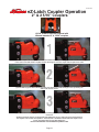
eZ-Latch Coupler Operation
2" & 2 5/16" Couplers
(4) 5/8" Grade 5 Bolts are required with
channel mounted 2" & 2 5/16" couplers
(1) eZ-Latch couplers do not require users to lift the handle for the coupler to engage the ball. Position the ball
in the center of the ball socket or slightly forward, then begin to lower the coupler with the jack on the trailer.
(2) At the mid-way point when lowering the trailer, the stem on the handle will begin to rise up allowing the
ball to enter the ball socket.
(3) Once the ball has fully engaged the socket the ball keeper will snap back into place securing the coupler
to the ball.
All Demco eZ-Latch couplers are tested and rated without the use of a safety pin and are not required for
the couplers to be used in safe operation. A security hole is available on all the eZ-Latch couplers to be
used in correlation with a lock for theft deterrence.
For more information visit www.demco-products.com
Page 12
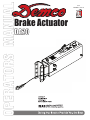
DEMCO MODEL DA20 BRAKE ACTUATOR
•
•
•
WARNING
To Prevent Serious Injury Or Death:
Review all of the following instructions before installation and use of hydraulic brake actuator.
Dealers or Distributors must review these instructions with ultimate user.
Failure to follow these instructions, or failure to properly maintain braking system after installation, can result in loss of braking action which could cause severe property damage, personal injury or death.
WARNING
Model DA20 brake actuator has a maximum load rating of 20,000 lbs. GVWR and 2,000 lbs. tongue load.
To avoid personal injury or death, do not exceed lowest of (1) the rated capacity of Model DA20 actuator, or (2)
rated capacity of ball, hitch, and coupler being used, or (3) trailer’s Gross Vehicle Weight Rating (GVWR).
Model DA20 brake actuator has a maximum tongue load equal to 10% of the maximum load rating.
SPECIAL NOTE – WHEN PRESSURE BLEEDING BRAKES IT IS STILL NECESSARY TO SHORT
STROKE THE MASTER CYLINDER SEVERAL TIMES TO ELIMINATE TRAPPED AIR BUBBLES.
Elevate tongue on trailer 4-6 inches
Refer to actuator parts breakdown page to locate referenced part numbers associated with procedures below:
Visually inspect actuator to ensure the inner slide is fully extended. This can be verified by making sure the black
copolymer slides (#20,#21,#22) are flush with leading edge of outer case.
*Failure to perform this function will prevent proper and complete bleeding of system*
•
•
•
•
•
Loosen or remove two 5/16” bolts (#17) that hold the lever guide and flat emergency lever spring (#15). Remove master cylinder fill cap (#12).
Using short strokes, pull forward on emergency lever (#16), pumping master cylinder until brake fluid in master
cylinder reservoir (#19)stops bubbling.
Attach a bleeder hose to a bleeder valve on one of the wheels (starting at wheel farthest from master cylinder )
and submerge other end into a transparent container partially filled with brake fluid to prevent possible splashing from container. NOTE: Disc brakes attach to top bleeder screw.
Loosen bleeder valve one turn and while watching fluid in container, use emergency lever (#16) to pump fluid
as long as bubbles continue to leave submerged hose. When bubbles stop, close bleeder valve, move to next
wheel and repeat until all brakes are bled. ( Note: Check master cylinder often (every 4-5 strokes) and refill
above half full as needed )
Refill master cylinder and securely attach cap (#12). Reinstall emergency lever spring, lever guide, lock washers and 5/16” hex head bolts. When tightening the bolts, make sure the lever moves freely in the groove in the
guide.
Test brakes by pulling emergency lever (#16) forward until it locks into position. Lever will be pointing approximately straight up. Attempt to rotate wheels in a forward direction. If any wheel rotates, brakes assemblies must
be adjusted. Jack up trailer and secure on adequate capacity jack stands. Follow trailer manufacturer’s recommendations for
lifting and supporting the unit. Make sure the wheel and drum rotates freely.
Remove the adjusting hole cover from the adjusting slot on the bottom of the brake backing plate.
With a screwdriver or standard adjusting tool, rotate the star wheel of the adjuster assembly to expand the brake
shoes. Adjust the brake shoes out until the pressure of the linings against the drum makes the wheel very difficult
to turn in forward direction.
Back off the adjuster wheel 15-20 clicks. The wheel should turn freely with a possible, slight lining drag.
Replace the adjusting hole cover and lower the wheel to the ground. Repeat the above procedure on all brakes.
For best results, the brakes should all be set at the same clearance.
*Retest the brakes by locking the emergency lever on and attempt to rotate tires in a forward direction, if
any wheel turns there might be trapped air in the system yet.
Page 13
SERVICING THE EMERGENCY LEVER
If emergency lever (#16) of actuator is applied, it can be disengaged by using a screwdriver to lift upward on front of flat emergency lever spring (#15) while pulling lever forward until released. A thorough inspection of emergency lever, emergency lever spring, and cable is required. Damaged parts must be replaced as follows:
A. Remove Cable (#27) from emergency lever (#16), emergency lever guide (#11) and flat emergency lever spring (#15), then pull lever out of actuator outer case (#9) through cross-slot in top.
B. Install new emergency lever through cross-slot in top of outer case. Attach new emergency lever spring and emergency lever guide.
C. Bolt emergency cable to emergency lever using bolt & locknut, leave loose enough to allow fork to pivot on lever.
D. Add adequate brake fluid to master cylinder and bleed brake system per instructions 4-6 in installation section.
Actuator Trouble Shooting Guide
Symptoms
Possible Solutions
Brakes Locking Up
Emergency lever partially pulled
Debris in master cylinder orifice
Debris/rust in master cylinder
Pinched brake line or hose
Brake cluster hanging up Release emergency lever.
(Lever must be in green zone).
(Emergency cable must have slack)
Clean/flush or replace orifice
Clean/flush or replace master cylinder
Replace brake line or hose.
Inspect wheel cylinder for rust and proper function
Check for broken springs
Check shoe adjustment (too tight)
Cluster mounting bracket bent
Trailer must be level or parallel with ground
Master cylinder lever will not pump fluid
Slide tube must be completely extended
Check fluid level.
Clean/flush or replace master cylinder
Clean/flush or replace orifice
Inspect line/hoses for blockages.
Check all line connections for air leaks
Check fluid level and bleed brakes
Master Cylinder Not Priming
Master cylinder orifice plugged
Brake fluid does not come out of orifice
Brake fluid does not come out of brake line
Air in brake lines
Leaking Master Cylinder
Brake fluid leaking out of push rod area
Brake fluid leaks out of gasket area
Brake fluid leaks out of gasket area
Brake fluid leaks around orifice
Repair or replace master cylinder.
Damaged gasket. Replace gasket.
Tighten master cylinder bolts in an alternating sequence
(10 inch lbs. torque)
Master cylinder tightened unevenly.
Replace gasket and tighten bolts alternating sequence.
Do not overfill master cylinder
When attaching main brake line to orifice, use line wrench and back-up wrench to prevent over-tightening
or damage to threads in master cylinder.
Jack trailer wheels up off ground.
Spin wheel/wheels. Wheels should spin freely.
Pull emergency lever on as far forward as possible,
wheels should not turn by hand. Release emergency lever.
Wheels should spin forward without resistance.
DO NOT LUBRICATE SLIDES
Brake Testing
Page 14
Rue Ring Installation
To install Rue Ring, place straight wire of Rue Ring through hole in pin as
shown in illustrations ( Figure B 1- 2)
Next, using a pliers, twist end of Rue Ring so the straight wire crosses over top
of the bent wire. ( Figure B 3)
Figure B illustration 4 shows removal of Rue Ring. Uncross wires, then while
lifting the bent wire, pull on loop end of the Rue Ring to remove from pin.
Figure A
Figure B
Install into hole.
Pin installed.
Bent leg behind
straight leg.
Lock position
Bent leg must
be on top of
straight leg then
Lockedpush up & back.
TO REMOVE
* Required for safe operation.
4010 320th St.
P.O. BOX 189, BOYDEN, IA. 51234
PH: (712) 725-2311 FAX: (712) 725-2380
TOLL FREE: 1-800-54DEMCO (1-800-543-3626)
www.demco-products.com
Page 16
Page 15
P.O. BOX 189
4010 320th St., BOYDEN, IA. 51234
PH: (712) 725-2311
FAX: (712) 725-2380
TOLL FREE: 1-800-54DEMCO (1-800-543-3626)
www.demco-products.com
Go online to www.demco-products.com for Demco
warranty policies & product registration.
Page 16