1
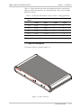
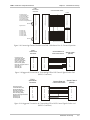
FLM-1
6/12 Port Fiber-Optic Multiplexer
Installation and Operation Manual
Notice
This manual contains information that is proprietary to RAD Data Communications. No part of this
publication may be reproduced in any form whatsoever without prior written approval by RAD Data
Communications.
No representation or warranties for fitness for any purpose other than what is specifically mentioned in
this manual is made either by RAD Data Communications or its agents.
For further information contact RAD Data Communications at the address below or contact your local
distributor.
International Headquarters
RAD Data Communications Ltd.
U.S. Headquarters
RAD Data Communications Inc.
24 Raoul Wallenberg St.
Tel Aviv 69719 Israel
Tel: 972-3-6458181
Fax: 972-3-6498250
E-mail: [email protected]
900 Corporate Drive
Mahwah, NJ 07430 USA
Tel: (201) 529-1100
Toll free: 1-800-444-7234
Fax: (201) 529-5777
E-mail: [email protected]
© 2001 RAD Data Communications
Publication No. 303-200-02/01
Warranty
This RAD product is warranted against defects in material and workmanship for a period of one year
from date of shipment. During the warranty period, RAD will, at its option, either repair or replace
products which prove to be defective. For warranty service or repair, this product must be returned to
a service facility designated by RAD. Buyer shall prepay shipping charges to RAD and RAD shall pay
shipping charges to return the product to Buyer. However, Buyer shall pay all shipping charges, duties
and taxes for products returned to RAD from another country.
Limitation of Warranty
The foregoing warranty shall not apply to defects resulting from improper or inadequate maintenance
by Buyer, Buyer-supplied firmware or interfacing, unauthorized modification or misuse, operation
outside of the environmental specifications for the product, or improper site preparation or
maintenance.
Exclusive Remedies
The remedies provided herein are the Buyer’s sole and exclusive remedies. RAD shall not be liable for
any direct, indirect special, incidental, or consequential damages, whether based on contract, tort, or
any legal theory.
Regulatory Information
FCC-15 User Information
This equipment has been tested and found to comply with the limits of the Class A digital device,
pursuant to Part 15 of the FCC rules. These limits are designed to provide reasonable protection against
harmful interference when the equipment is operated in a commercial environment. This equipment
generates, uses and can radiate radio frequency energy and, if not installed and used in accordance
with the instruction manual, may cause harmful interference to the radio communications. Operation
of this equipment in a residential area is likely to cause harmful interference in which case the user will
be required to correct the interference at his own expense.
Warning per EN 55022
This is a Class A product. In a domestic environment, this product may cause radio interference, in
which case the user may be required to take adequate measures.
Safety Warnings
The exclamation point within a triangle is intended to warn the operator or
service personnel of operation and maintenance factors relating to the
product and its operating environment which could pose a safety hazard.
Always observe standard safety precautions during installation, operation and maintenance of this
product. Only a qualified and authorized service personnel should carry out adjustment, maintenance
or repairs to this instrument. No adjustment, maintenance or repairs should be performed by either the
operator or the user.
Telecommunication Safety
The safety status of each of the ports on the FLM-1 is declared according to EN 41003 and is detailed
in the table below:
Ports
Safety Status
DTE
SELV
Circuit operating with Safety Extra-Low Voltage
4W
TNV-1
Circuit whose normal operating voltage does not
exceed the limits of SELV, but is subject to
overvoltages from Telecommunications Networks.
Declaration of Conformity
Manufacturer’s Name:
RAD Data Communications Ltd.
Manufacturer’s Address:
24 Raoul Wallenberg St.
Tel Aviv 69719
Israel
declares that the product:
Product Name:
FLM-1
Conforms to the following standard(s) or other normative document(s):
EMC:
EN 55022 (1994) Limits and methods of measurement of
radio disturbance characteristics of information technology
equipment.
EN 50082-1 (1992)
Electromagnetic compatibility Generic immunity standards for residential, commercial and
light industry.
Safety:
EN 60950 (1992/93)
Safety of information technology
equipment, including electrical business equipment.
Supplementary Information:
The product herewith complies with the requirements of the EMC Directive 89/336/EEC and the Low
Voltage Directive 73/23/EEC. The product was tested in a
typical configuration.
Tel Aviv, October 29th, 1996
Haim Karshen
VP Quality
European Contact: RAD Data Communications GmbH, Berner Strasse 77, 60437 Frankfurt am Main, Germany
Contents
CHAPTER 1 INTRODUCTION
1.1 Overview ....................................................................................................................... 1-1
General ................................................................................................................................ 1-1
Versions................................................................................................................................ 1-1
Applications.......................................................................................................................... 1-1
1.2 Physical Description ....................................................................................................... 1-3
Front Panel ........................................................................................................................... 1-4
Rear Panel ............................................................................................................................ 1-4
1.3 Functional Description ................................................................................................... 1-4
1.4 Technical Specifications ................................................................................................. 1-5
Subchannels ......................................................................................................................... 1-5
Main Channel ....................................................................................................................... 1-5
Diagnostics ........................................................................................................................... 1-6
Power................................................................................................................................... 1-7
Physical ................................................................................................................................ 1-7
Environment ......................................................................................................................... 1-7
CHAPTER 2 INSTALLATION AND SETUP
2.1 Introduction ................................................................................................................... 2-1
2.2 Site Requirements and Prerequisites .............................................................................. 2-1
2.3 Package Contents........................................................................................................... 2-1
2.4 Installation and Setup..................................................................................................... 2-2
Setting the Internal Jumpers .................................................................................................. 2-2
Connecting the Interfaces...................................................................................................... 2-3
Connecting the Subchannels ................................................................................................. 2-4
Connecting the Power........................................................................................................... 2-7
CHAPTER 3 OPERATING INSTRUCTIONS
3.1 General.......................................................................................................................... 3-1
3.2 Front Panel Indicators and Switches ............................................................................... 3-1
3.3 Operating Instructions.................................................................................................... 3-2
Power Turn-On .................................................................................................................... 3-2
Operation............................................................................................................................. 3-2
Power Turn-Off .................................................................................................................... 3-2
Operational Field Strapping Changes..................................................................................... 3-2
FLM-1 Installation and Operation Manual
i
Contents
CHAPTER 4 TROUBLESHOOTING AND DIAGNOSTICS
4.1 Frequently Asked Question ............................................................................................ 4-1
4.2 Diagnostics Tests ............................................................................................................ 4-1
Local Loopback..................................................................................................................... 4-2
Remote Loopback................................................................................................................. 4-2
4.3 Fault Isolation and Troubleshooting ................................................................................ 4-2
APPENDIX A PIN ASSIGNMENT FOR SUBCHANNELS WITH DB-25 CONNECTORS
APPENDIX B PINOUT FOR RJ-45 CONNECTORS
ii
FLM-1 Installation and Operation Manual
List of Figures
Figure 1-1 Typical Point-to-Point Application................................................................................ 1-2
Figure 1-2 Typical Ring Installation ............................................................................................... 1-2
Figure 1-3 FLM-1 3D View ........................................................................................................... 1-3
Figure 2-1 Strapping Diagram ....................................................................................................... 2-3
Figure 2-2 FLM-1/4W Rear Panel with a Terminal Block Main Link Connector ............................. 2-3
Figure 2-3 FLM-1/4W Rear Panel with an RJ-45 Main Link Connector.......................................... 2-3
Figure 2-4 FLM-1/DF Rear Panel with a DF Main Link Connector................................................. 2-3
Figure 2-5 FLM-1/4W Rear Panel with RJ-45 Main Link and Subchannel Connectors ................... 2-4
Figure 2-6 FLM-1/DF Rear Panel with STA Main Link and RJ-45 Subchannel Connectors ............ 2-4
Figure 2-7 FLM-1/4W Rear Panel with Main Link Terminal Block and RJ-45 Subchannel
Connectors ............................................................................................................................. 2-4
Figure 2-8 Connecting Channel Doubler to an FLM-1 Subchannel for 12 Channel Operation....... 2-5
Figure 2-9 Suggested Connection for Transmitting DTR to DSR Control Signals End-to-End
(DB-25 Connectors) ................................................................................................................ 2-5
Figure 2-10 Suggested Connection for Transmitting RTS to DCD Control Signals End-to-end
(DB-25 Connectors) ................................................................................................................ 2-5
Figure 2-11 Suggested Connection for Transmitting DTR to DSR Control Signals End-to-End
(RJ-45 Connectors).................................................................................................................. 2-6
Figure 2-12 Suggested Connection for Transmitting RTS to DCD Control Signals End-to-end
(RJ-45 Connectors).................................................................................................................. 2-6
Figure 3-1 FLM-1 Front Panel ....................................................................................................... 3-1
List of Tables
Table 1-1 Distortion and Number of Sites for FLM-1 in Ring Application ....................................... 1-3
Table 1-2 Performance in Various Modes of Operation ................................................................. 1-4
Table 3-1 FLM-1 Indicators and Switches ...................................................................................... 3-2
Table 4-1 Fault Isolation and Troubleshooting................................................................................ 4-3
FLM-1 Installation and Operation Manual
iii
List of Tables
iv
FLM-1 Installation and Operation Manual
Chapter 1
Introduction
1.1 Overview
General
FLM-1 is a full duplex time division asynchronous multiplexer enabling up
to twelve async terminals to be multiplexed onto a single channel. FLM-1 is
intended for use in manufacturing facilities, building complexes, campuses
and other similar point-to-point and ring applications.
Versions
One of the following media options for the main channel interface is
available with the unit:
•
Electrical option (FLM-1/4W): 4-wire for transmission over two twisted
pairs (terminal block or RJ-45 connector)
•
Optical option (FLM-1/DF): Dual fiber for transmission over dual
fiber-optic cable.
Secondary channels are represented by six DB-25 connectors or 12 RJ-45
connectors. For detailed information about main and secondary channel
options see Section 1-4, “Technical Specifications” and Connecting the
Interfaces in Section 2-5.
Applications
Point-to-Point Application
FLM-1 is used mainly for point-to-point configurations where distances of
up to several kilometers are involved. Figure 1-1 shows a typical application
where a cluster of terminals is connected to a host computer through a
single link.
Maximum data rate on each FLM-1 subchannel is 19.2 kbps for the 4-wire
version and 38.4 kbps for the dual-fiber version, with 12.5% distortion
when working with 6 data channels and 25% distortion when working with
12 data channels or 6 data + 6 control channels.
16/01/01 11:12 AM
Overview
1-1
FLM-1 Installation & Operation Manual
Chapter 1 - Introduction
Figure 1-1 Typical Point-to-Point Application
Ring Application
For installations involving clusters of terminals distributed in several
locations, FLM-1 units may be installed in a ring-type configuration, as
shown in Figure 1-2.
4
TERM
T
1
2-WIRE
FLM-1
HOST
12
1
R
4
FLM-1
R
T
2-WIRE
2-WIRE
T
4
TERM
4
TERM
R
9
12
FLM-1
2-WIRE
FLM-1
5
8
R
T
Figure 1-2 Typical Ring Installation
Note
1-2
Overview
In this application, the unconnected channels at each site must be bypassed
by shorting Pins 2 and 3 of the relevant subchannel connector.
16/01/01 11:12 AM
FLM-1 Installation & Operation Manual
Chapter 1 - Introduction
Table 1-1 shows distortion per node and maximum number of nodes/sites
allowed for different data rates on each subchannel, for the 4-wire and the
dual-fiber versions.
Table 1-1 Distortion and Number of Sites for FLM-1 in Ring Application
Data Rate
(kbps)
Distortion per Node (%)
Number of Nodes/Sites
4 wire
Fiber
4 wire
Fiber
19.2
25.00
12.50
2
4
9.6
12.50
6.250
3
4
4.8
6.250
3.125
4
8
2.4
3.125
1.5625
8
16
1.2
1.5625
0.78125
16
32
1.2 Physical Description
A 3D view of FLM-1 is shown in Figure 1-3.
Figure 1-3 FLM-1 3D View
16/01/01 11:12 AM
Physical Description
1-3
FLM-1 Installation & Operation Manual
Chapter 1 - Introduction
Front Panel
The front panel provides control over the operation of the unit. The LEDs
provide real-time indications related to the operation and status of the unit.
Two push-button switches allow test loopbacks for the FLM-1 diagnostics.
For details, see Chapter 3, “Operation” and Chapter 4, “Troubleshooting
and Diagnostics”.
Rear Panel
The rear panel of the unit allows access to interface and power
connections. For details, see Chapter 2, “Installation”.
1.3 Functional Description
FLM-1 can operate in two operation modes: set to 6 or 12 channels, which
is controlled by a user-selectable strap. When the unit is set for six channels,
each channel can be used to transmit full duplex data end-to-end. When
the unit is set for twelve channels, each subchannel can be used for either
data or control signal transmission, according to the specific application. For
example:
•
Note
In the case of DB-25 connectors version, this mode requires a channel
doubler cable (see Section 2.4 for details).
•
Note
All twelve channels can be used to transmit full duplex data end-to-end.
Six channels can be used to transmit full duplex data and six can be used
to transmit control signals end-to-end.
This operation mode requires a channel doubler of another type. This channel
double would be different for different types of subchannel connectors
(DB-25 or RJ-45) and different types of control signal. For more information
see Connecting the Interface in Section 2-5.
Multiplexing is implemented by using an over-sampling technique. Each of
the twelve channels is sampled at 78.6 kbps for the electrical (4-wire) option
or at 157.2 kbps for the optical (fiber) option.
Table 1-2 summarizes the FLM-1 performance with various options and
modes of operation.
Table 1-2 Performance in Various Modes of Operation
1-4
No. of
Max
Subchannels
in Use
Data Rate
(kbps)
4 Wire
Fiber
6
19.2
12.5
6.25
6
38.4
-
12.5
12
19.2
25.0
12.5
12
38.4
-
25.0
Functional Description
Distortion (%)
16/01/01 11:12 AM
FLM-1 Installation & Operation Manual
Note
Chapter 1 - Introduction
1. The distortion refers to the duty cycle and not to the voltage level.
2. Whenever possible (if the number of channels is less than or equal to 6) it
is recommended to operate FLM-1 in the six-channel mode, which results in
less distortion.
1.4 Technical Specifications
Subchannels
Transmission format
Asynchronous
Data rate
Optical interface: up to 38.4 kbps
Electrical interface: up to 19.2 kbps
Main Channel
16/01/01 11:12 AM
Distortion
See Table 1-2
Interface
RS-232/V.24
Number of subchannels
Up to six or up to twelve,
depending on the version and
availability of a channel doubler
(see Section 2.4)
Connectors
Six D-type 25-pin, female, or
twelve RJ-45
Mode of operation
Full-duplex
Electrical Interface
Transmission line
4-wire unconditioned telephone
lines (two twisted pairs)
Operating range
Maximum of 1.6 km (1 mile) on
22 AWG cable
Data rate
1.2288 Mbps
Output format
Balanced, transformer isolated,
6V peak-to-peak (on 100Ω)
Input resistance
100Ω
Connector
Terminal block or RJ-45
Technical Specifications
1-5
FLM-1 Installation & Operation Manual
Chapter 1 - Introduction
Optical Interface
Transmission line
Double optical cable
Operating range
for 850 nm:
up to 5 km (3.1 miles)
for 1300 nm:
up to 40 km (25 miles) with
attenuation of of 0.5 dB/km with
9/125µ fiber optic cable
Data rate
2.4576 Mbps
Operating wavelength
850 nm or 1300 nm
Optical output level
Diagnostics
Switches and
Indicators
1-6
for 850 nm:
-24 dBm min into 50/125 fiber
-20 dBm min into 62.5/125 fiber
for 1300 nm:
-18 dBm min into 9/125 fiber
Receiver sensitivity
-40 dBm min
Dynamic range
24 dB
Connectors
Standard SMA or ST connectors
In compliance with ITU V.54
Local digital loopback
Activated by the LLB push button
Remote digital loopback
Activated by the RLB push button
POWER LED (Green)
ON when the unit is powered
TEST LED (Yellow)
ON when the local or remote unit
is performing a loopback
LOCAL SYNC LOSS LED (Red)
ON when synchronization is lost at
the local unit
REMOTE SYNC LOSS LED (Red)
ON when synchronization is lost at
the remote unit
LLB Switch
When pressed, the unit is
performing local loopback
RLB Switch
When pressed, the unit is
performing remote loopback
Technical Specifications
16/01/01 11:12 AM
FLM-1 Installation & Operation Manual
Chapter 1 - Introduction
Power
100/115/230 VAC (± 10%), 50-60 Hz, 7.5 VA Max
Physical
Height
4.4 cm / 1.72 in (1U)
Width
33.8 cm / 13.30 in
Depth
22.0 cm / 8.60 in
Weight
1.6 kg / 3.50 lb
Temperature
Humidity
0-50°C / 32-122°F
Up to 90%, non-condensing
Environment
16/01/01 11:12 AM
Technical Specifications
1-7
Chapter 1 - Introduction
1-8
Technical Specifications
FLM-1 Installation & Operation Manual
16/01/01 11:12 AM
Chapter 2
Installation and Setup
2.1 Introduction
This chapter provides instructions for mechanical and electrical installation
of FLM-1.
Sections 2.2 and 2.3 describe site preparation for installation of FLM-1.
Section 2.4 describes mechanical and electrical installation, including strap
selection, setting the internal jumpers, connecting the main link and
subchannel interfaces and connecting the power.
After completing installation, refer to Chapter 3 for operating information
and system checkout to ensure proper operation.
2.2 Site Requirements and Prerequisites
Install FLM-1 within 1.5m (5 ft) of an easily accessible grounded AC outlet.
The outlet should be capable of furnishing the voltage in accordance with
the rated voltage of the unit.
Allow at least 90 cm (36 in) of frontal clearance for operating and
maintenance accessibility. Allow at least 10 cm (4 in) clearance at the rear of
the unit for signal lines and interface cables.
2.3 Package Contents
The FLM-1 package includes the following items:
16/01/01 11:12 AM
•
The FLM-1 unit
•
The FLM-1 Installation and Operation Manual
•
The AC power cord.
Package Contents
2-1
Chapter 2 - Installation and Setup
FLM-1 Installation & Operation Manual
2.4 Installation and Setup
The FLM-1 units are delivered completely assembled. The units are designed
for desktop installation or mounting in a 19-inch rack. Installation
procedures for the FLM-1 unit are provided in the following paragraphs. For
rack installation of FLM-1, refer to the Rack Mounting Kit for 19-inch Racks
guide that comes with the RM kit.
To complete the installation of FLM-1, you must perform the following (in
the given order):
Setting the
Internal Jumpers
•
Determine the required configuration of FLM-1, according to your
application, and set the internal jumpers accordingly.
•
Connect the subchannel and main link interfaces.
•
Connect power to the unit.
Before connecting the interfaces and power to the unit, determine the
required configuration of FLM-1 and position the straps accordingly. To do
this, proceed as follows:
Access to the inside of the equipment is permitted only to authorized
and qualified service personnel.
Warning
To avoid accidental electric shock, always disconnect the power cord
before removing the unit from its casing.
1. Unscrew the upper cover screw located at the back of the unit.
2. Slide the rear drawer out.
3. Locate the strap marked “SELECT 6 OR 12 CHANNELS” on the circuit
board. For up to 6 channels with no control applications, place the strap
to 6. For any other application, place the strap to 12 (see Figure 2-1).
4. Locate the strap marked GND. According to your requirements, set the
signal ground to be connected to shielding (chassis) ground or floating
(NC). The factory setting is GND connected to Chassis ground. This
setting is strongly recommended unless it is absolutely necessary to do
otherwise.
5. Slide the rear drawer back to its place.
6. Fasten the upper cover screw at the back of the unit.
Caution
2-2
The safety status of the 4W port is TNV-1, operating within the limits of
SELV. If the 4W network does not fulfill this requirement, the signal ground
must be connected to the chassis ground.
Installation and Setup
16/01/01 11:12 AM
FLM-1 Installation & Operation Manual
Chapter 2 - Installation and Setup
GND
32
NC
12
SELECT
6 OR 12
6 CHANNELS
J1
Figure 2-1 Strapping Diagram
Connecting the
Interfaces
Figure 2-2 to Figure 2-7 show the FLM-1 rear panel in all its versions,
containing different main link and subchannel connectors.
Figure 2-2 to Figure 2-4 show the FLM-1 versions with DB-25 subchannel
connectors and different main link connectors: terminal block, RJ-45, and
dual fiber.
Figure 2-5 to Figure 2-7 show the FLM-1 versions with RJ-45 subchannel
connectors and different main link connectors: terminal block, RJ-45, and
dual fiber.
MAIN
CHANNEL
RX-B RX-A
TX-B TX-A
115 VAC
0.2A T 250V
CH
1/7
CH
2/8
CH
3/9
CH
4/10
CH
5/11
CH
6/12
Figure 2-2 FLM-1/4W Rear Panel with a Terminal Block Main Link Connector
MAIN
CHANNEL
115 VAC
0.2A T 250V
CH
1/7
CH
2/8
CH
3/9
CH
4/10
CH
5/11
CH
6/12
Figure 2-3 FLM-1/4W Rear Panel with an RJ-45 Main Link Connector
MAIN
CHANNEL
115 VAC
0.2A T 250V
RX
CH 1/7
CH 2/8
CH 3/9
CH 4/10
CH 5/11
CH 6/12
TX
Figure 2-4 FLM-1/DF Rear Panel with a DF Main Link Connector
16/01/01 11:12 AM
Installation and Setup
2-3
FLM-1 Installation & Operation Manual
Chapter 2 - Installation and Setup
MAIN
SUBCHANNELS
CHANNEL
1
2
3
4
5
6
7
8
9
10
11
12
115 VAC
0.2A T 250V
Figure 2-5 FLM-1/4W Rear Panel with RJ-45 Main Link and Subchannel Connectors
MAIN
CHANNEL
SUBCHANNELS
1
2
3
4
5
6
7
8
9
10
11
12
115 VAC
0.2A T 250V
RX
TX
Figure 2-6 FLM-1/DF Rear Panel with STA Main Link and RJ-45 Subchannel Connectors
MAIN CHANNEL
RX-B RX-A
SUBCHANNELS
TX-B TX-A
1
115 VAC
0.2A T 250V
2
3
4
5
6
7
8
9
10
11
12
Figure 2-7 FLM-1/4W Rear Panel with Main Link Terminal Block and RJ-45 Subchannel
Connectors
Connecting the Subchannels
DB-25 Connectors
In this version, six D-type 25-pin female connectors on the rear panel
(see Figures 2-2 to 2-4) enable connection to the unit. Detailed
information about the signals present at these connectors is given in
Appendix A.
To have FLM-1 operating in a 6-channel mode, use standard cables with
DB-25 male connectors.
To have FLM-1 operating in a 12-channel mode, use channel doubler
cables (CD). You can order these cables from RAD or make them yourself
according to pinout shown in Figure 2-8 below.
To have FLM-1 operating in a 6-channel operation with full duplex data
and control signals transmitted end-to-end, you have to make special
cables (not provided by RAD). Figure 2-9 shows suggested pin connections
for transmitting a DTR-to-DSR control signal and Figure 2-10 those for
transmitting an RTS-to-DCD control signal.
2-4
Installation and Setup
16/01/01 11:12 AM
FLM-1 Installation & Operation Manual
Chapter 2 - Installation and Setup
FLM-1
Subchannel
Connector
Channel Doubler Cable
Port A
1
2
3
4
5
6
8
15
17
20
24
7
Protective Ground
Transmitted Data (TD)
Received Data (RD)
Request to Send (RTS)
Clear to Send (CTS)
Data Set Ready (DSR)
Received Line Signal Detector
Not Used
Signal Ground
1
2
3
4
5
6
8
15
17
20
24
7
1
2
3
4
5
6
8
15
17
20
24
7
Port B
14
16
19
13
21
12
11
18
25
23
Secondary TD
Secondary RD
Secondary RTS
Secondary CTS
Secondary DSR
Secondary RLSD
Not Used
1
2
3
4
5
6
8
15
17
20
24
7
14
16
19
13
21
12
11
18
25
23
Figure 2-8 Connecting Channel Doubler to an FLM-1 Subchannel for 12 Channel Operation
FLM-1
Subchannel
Connector
Protective Ground
Transmitted Data (TD)
Received Data (RD)
Request to Send (RTS)
Clear to Send (CTS)
Data Set ready (DSR)
Received Line Signal Detector
Signal Ground
Secondary TD
Secondary RD
1
2
3
4
5
6
8
7
14
16
Channel Data and
Control Connection
1
2
3
4
5
6
7
8
14
16
Special Cable 1
(DB-25)
1
2
3
4
5
6
7
8
20
Figure 2-9 Suggested Connection for Transmitting DTR to DSR Control Signals End-to-End
(DB-25 Connectors)
FLM-1
Subchannel
Connector
Protective Ground
Transmitted Data (TD)
Received Data (RD)
Request to Send (RTS)
Clear to Send (CTS)
Data Set ready (DSR)
Received Line Signal Detector
Signal Ground
Secondary TD
Secondary RD
1
2
3
4
5
6
8
7
14
16
Channel Data and Special Cable 2
(DB-25)
Control Connection
1
2
3
4
5
6
8
7
14
16
1
2
3
4
5
6
7
8
Figure 2-10 Suggested Connection for Transmitting RTS to DCD Control Signals End-to-end
(DB-25 Connectors)
16/01/01 11:12 AM
Installation and Setup
2-5
FLM-1 Installation & Operation Manual
Chapter 2 - Installation and Setup
RJ-45 Connectors
Twelve RJ-45 modular jacks on the rear panel (see Figures 2-5 to 2-7)
each support a single channel. Pinout for this option is given in
Appendix B.
The six-channel operation with full duplex data and transmitting control
signals end-to-end requires special cables (not provided by RAD).
Figure 2-11 shows suggested pin connections for transmitting a
DTR-to-DSR control signal and Figure 2-12 those for transmitting an
RTS-to-DCD control signal.
FLM-1
Subchannel
Connector
Channels 1-6
Channels 7-12
Protective Ground
Transmitted Data (TD)
Received Data (RD)
Request to Send (RTS)
Clear to Send (CTS)
Data Set ready (DSR)
Received Line Signal Detector
Signal Ground
Secondary TD
Secondary RD
Channel Data and
Control Connection
1
5
3
2
8
6
4
7
1
5
3
2
8
6
4
7
5
3
n/c
n/c
n/c
n/c
n/c
n/c
5
3
n/c
n/c
n/c
n/c
n/c
n/c
Special Cable 1
(DB-25)
1
2
3
4
5
6
8
20
7
Figure 2-11 Suggested Connection for Transmitting DTR to DSR Control Signals End-to-End
(RJ-45 Connectors)
FLM-1
Subchannel
Connector
Channels 1-6
Channels 7-12
Protective Ground
Transmitted Data (TD)
Received Data (RD)
Request to Send (RTS)
Clear to Send (CTS)
Data Set ready (DSR)
Received Line Signal Detector
Signal Ground
Secondary TD
Secondary RD
Channel Data and
Control Connection
1
5
3
2
8
6
4
7
1
5
3
2
8
6
4
7
5
3
n/c
n/c
n/c
n/c
n/c
n/c
5
3
n/c
n/c
n/c
n/c
n/c
n/c
Special Cable 2
(DB-25)
1
2
3
4
5
6
7
8
Figure 2-12 Suggested Connection for Transmitting RTS to DCD Control Signals End-to-end
(RJ-45 Connectors)
2-6
Installation and Setup
16/01/01 11:12 AM
FLM-1 Installation & Operation Manual
Chapter 2 - Installation and Setup
Connecting the Main Channel
4-wire Version - Terminal Block
A 5-screw terminal block is located at the rear panel (see Figures 2-2
and 2-7). Five wires, marked TX-A, TX-B, RX-A, RX-B and CHASSIS GND
connect transmit and receive wires and the cable shield (if available).
To connect the main link with the terminal block, proceed as follows:
1.
Connect TX connectors at the local unit to RX connectors at the
opposite unit.
2.
Connect RX connectors at the local unit to TX connectors at the
opposite unit.
3.
Connect the ground wires, if necessary.
4-Wire Version - RJ-45 Jack
Pinout for this version is given in Appendix B.
Dual-Fiber Version
Two SMA or ST connectors, marked TX and RX, are located on the rear
panel. To connect the interface, proceed as follows:
1.
Remove the protective caps from the connectors and keep them in a
safe place for later use.
2.
Clean both connectors to remove dust accumulated during shipment
(using ethanol or a similar cleaning fluid).
3.
Connect the transmit fiber to the TX connector and the receive fiber to
the RX connector, and secure the fastening nuts.
At the remote unit, the transmit fiber must be connected to RX and the
receive fiber to TX.
Caution
Connecting the
Power
16/01/01 11:12 AM
Do not overtighten the fiber-optic connectors.
AC power is supplied to the FLM-1 through a 1.5 m (5 ft) cord terminated
by a grounded 3-wire plug. The AC cord is fused at the rear panel AC
power receptacle of the unit. A slow-blow fuse of 0.1A is required for
230 VAC operation, and a slow-blow 0.2A fuse for 115 VAC operation.
Installation and Setup
2-7
Chapter 2 - Installation and Setup
Warning
FLM-1 Installation & Operation Manual
Before connecting power to the unit, verify that the socket outlet is
provided with a protective earth contact. If you are using an extension
cord (power cable) make sure it is grounded as well.
Interrupting the protective (grounding) conductor (inside or outside the
unit), or disconnecting the protective earth terminal can make this unit
dangerous.
Make sure that only fuses of the required rating, as marked on the rear
panel, are used for replacement. Do not use repaired fuses or
short-circuit the fuse holder. Always disconnect the mains cable before
removing or replacing the fuse. Whenever it is likely that the fuse
protection has been damaged, make the unit inoperative.
To connect power to FLM-1, simply insert its power cord into the power
socket.
2-8
Installation and Setup
16/01/01 11:12 AM
Chapter 3
Operating Instructions
3.1 General
This chapter covers:
•
A list of controls and indicators together with their functions.
•
An operating procedure covering power turn-on, operating
instructions, and power turn-off.
•
Information on strapping.
Before operating FLM-1, complete all the installation procedures
described in Chapter 2.
3.2 Front Panel Indicators and Switches
The FLM-1 front panel is shown in Figure 3-1.
SYNC LOSS
POWER
TEST
LOCAL REMOTE
LLB
RLB
Figure 3-1 FLM-1 Front Panel
09/01/01 4:29 PM
Front Panel Indicators and Switches
3-1
FLM-1 Installation & Operation Manual
Chapter 3 - Operation
Table 3-1 lists the functions of the FLM-1 indicators and switches.
Table 3-1 FLM-1 Indicators and Switches
Identification
No
Name
Type
Function
1
POWER
LED Indicator
(green)
Lights up when the unit is powered.
2
TEST
LED Indicator
(yellow)
Lights up when either local or remote unit is
performing a loopback test.
3
SYNC LOSS LOCAL
LED Indicator
(red)
Lights up when synchronization is lost at the local
unit.
4
SYNC LOSS REMOTE
LED Indicator
(red)
Lights up when synchronization is lost at the
remote unit.
5
LLB
Push button
When pressed (pushed in), the unit performs a
local loopback.
6
RLB
Push button
When pressed (pushed in), the unit performs a
remote loopback.
Note
Pressing LLB and RLB simultaneously has no effect; the unit just continues to
operate normally.
3.3 Operating Instructions
Power Turn-On
To apply AC power to FLM-1, connect its power cord to an acceptable AC
source. The POWER LED should light up. If the local and remote FLM-1
units are in operation and properly connected via the main channel, no
other indicator should be ON. If it is not so, refer to Chapter 4 for
troubleshooting information.
Operation
FLM-1 operates entirely unattended except when performing system tests.
Power Turn-Off
To turn off FLM-1, simply remove the AC power cord from the AC source.
Operational Field If it becomes necessary to reconfigure FLM-1 for twelve-channel mode or
six-channel mode operation, follow the appropriate setup procedure
Strapping
described in Section 2.4.
Changes
Access to the inside of the equipment is permitted only to authorized
and qualified service personnel.
Warning
3-2
Operating Instructions
09/01/01 4:29 PM
Chapter 4
Troubleshooting and
Diagnostics
4.1 Frequently Asked Question
Question: How can I connect six pairs of DTEs for transferring Data and
Control Signals (RTS to DCD) end-to-end?
Answer: First set the jumper marked “SELECT 6 OR 12 CHANNELS” to the
“12” position. Now FLM-1 passes 12 pairs of signals (TD and RD of channels
1 to 6 and secondary TD and RD of channels 7 to 12) end-to-end. All the
other channel signals are local: they do not pass end-to-end, being
transmitted between FLM-1 and the DTE (see Table B-2).
To transfer the control signals end-to-end, you must make a special cable. If
you have a model with DB-25 subchannel connectors, for exact wiring see
Figure 2-10; if your model has RJ-45 subchannel connectors, see
Figure 2-12. This way you are using channel 1 to pass the data signals
end to-end, and channel 7 (secondary channel) to pass the RTS and DCD
signals end-to-end.
4.2 Diagnostics Tests
FLM-1 features ITU V.54 diagnostic capabilities for performing loopback
tests. FLM-1 supports two types of loopback tests: a local loopback and
remote loopback.
Note
09/01/01 4:29 PM
Before you start to perform any of the loopback tests, set to OFF (negative
voltage) the following signals at the remote unit subchannels:
- Received Data (Circuit 104)
- Clear to Send (Circuit 106)
- Receive Line Signal Detector (Circuit 109)
Diagnostics Tests
4-1
Chapter 4 - Troubleshooting and Diagnostics
Local Loopback
FLM-1 Installation & Operation Manual
When FLM-1 performs a local loopback, the data from the local transmitter
is looped back to the local receiver at the digital level, thus checking all
local digital circuitry for proper operation.
To activate the test, press the LLB push button located on the front panel. If
the local unit is operating properly, the yellow TEST indicator should light
up and all other indicators should be OFF.
If the local and remote units are properly connected via the main channel,
this test also checks the following:
• Local transmitter analog interface
• Remote analog section
• Digital receiver section.
In this case the yellow TEST indicator on the remote unit should also be lit
up.
Remote
Loopback
The remote loopback loops back data from the remote receiver to the
remote transmitter, thus checking:
•
•
•
•
All local digital circuitry
Both local and remote analog interfaces
Main channel link
Remote digital receiver section.
To activate the test, press the RLB push button on the front panel. If both
local and remote units operate properly, the yellow TEST indicators should
be lit at both units and all other indicators should be OFF.
4.3 Fault Isolation and Troubleshooting
The symptoms and corresponding procedures listed in Table 4-1 will help
you identify, isolate, and correct faults in accordance with the tools
available.
Warning
4-2
These service instructions are for use by qualified personnel only. To
avoid electric shock, do not perform any servicing other than that
contained in the operating instructions unless you are qualified to do so.
Fault Isolation and Troubleshooting
09/01/01 4:29 PM
FLM-1 Installation & Operation Manual
Chapter 4 - Troubleshooting and Diagnostics
Table 4-1 Fault Isolation and Troubleshooting
Symptom
All front panel
indicators are OFF
Action
1. Check that power is supplied to the unit.
2. Check the fuse inside the AC receptacle on the rear panel and replace it
with a new one.
3. Replace the unit. The fault is probably in the unit's power supply circuits.
LOCAL SYNC
LOSS LED is ON
1. Perform an LLB test as described in Section 4-1. The yellow TEST LED
should light and LOCAL SYNC LOSS should go OFF. If this does not
happen, replace the local unit. Otherwise proceed to step 2.
2. Perform an RLB test. The yellow TEST LED should light and LOCAL
SYNC LOSS should go OFF. If this does not happen, replace the local
unit. Otherwise proceed to step 3.
3. Perform steps 1 and 2 at the remote site. If the fault is still not located,
replace both units one at a time. If the problem persists, the main
channel link between the units is probably defective and should be
checked.
REMOTE SYNC
LOSS LED is ON
4. Perform an LLB test at the remote unit. The yellow TEST LED should light
and LOCAL SYNC LOSS should go OFF. If this does not happen, replace
the remote unit. Otherwise proceed to step 2.
5. Perform an RLB test at the remote unit. The yellow TEST LED should light
and LOCAL SYNC LOSS should go OFF. If this does not happen, replace
the remote unit. Otherwise proceed to step 3.
6. Perform steps 1 and 2 at the local site. If the fault is still not located,
replace both units one at a time. If the problem persists, the main
channel link between the units is probably defective and should be
checked.
09/01/01 4:29 PM
Fault Isolation and Troubleshooting
4-3
Chapter 4 - Troubleshooting and Diagnostics
4-4
Fault Isolation and Troubleshooting
FLM-1 Installation & Operation Manual
09/01/01 4:29 PM
Appendix A
Pin Assignment for
Subchannels with DB-25
Connectors
Table A-1 Pin Assignment for Subchannels with DB-25 Connectors
V.24
RS-232
Pin
Signal
Description
101
AA
1
Protective Ground
Chassis ground. May be isolated from
signal ground (see Section 2-4).
102
AB
7
Signal Ground
Common signal and DC power supply
ground.
103
BA
2 (14)
TD - Transmit Data
Serial digital data into FLM-1, end-to-end.
104
BB
3 (16)
RD - Receive Data
Serial digital data output from FLM-1,
end-to-end.
105
CA
4 (19)
RTS - Request To Send
A positive level to FLM-1 when data
transmission is desired, shorted to CTS.
106
CB
5 (13)
CTS - Clear To Send
A positive level from FLM-1 (if data
transmission is possible), shorted to RTS.
107
CC
6 (21)
DSR - Data Set Ready
A positive DC voltage (+8V) from FLM-1
indicating that the unit is powered.
109
CF
8 (12)
DCD - Receive Line Signal
Detector (Carrier Detect)
A positive level from FLM-1 except when
either a sync loss occurs or remote
loopback is performed.
−
−
9
This signal (+8V) is reserved for data set
testing and for powering miniature
modems
10
This signal (-8V) is reserved for data set
testing and for powering miniature
modems
Note
09/01/01 4:29 PM
Pin numbers in parentheses are for the secondary channel, available when using a
channel doubler cable (working in 12-channel operation mode).
A-1
Appendix A - Pin Assignment for Subchannels with DB-25 Connectors
A-2
FLM-1 Installation & Operation Manual
09/01/01 4:29 PM
Appendix B
Pinout for RJ-45
Connectors
The pinouts of the RJ-45 connectors for the FLM-1 line (main channel) and
subchannels are given in Tables B-1 and B-2, respectively.
Table B-1
Pin
Signal
1
RX
2
RX
3
NC
4
NC
5
NC
6
NC
7
TX
8
TX
Table B-2
Pin
Main Channel Pinout
Signal
Subchannel Pinout
Note
1
V+
2
RTS
Shorted to CTS
3
RXD
End-to-end, from FLM-1
4
DCD
According to main link sync
status
5
TXD
End-to-end, into FLM-1
6
DSR
Always +8V
7
Signal GND
8
CTS
Shorted to RTS
B-1
Appendix B - Pinout for RJ-45 Connectors
B-2
FLM-1 Installation & Operation Manual