1
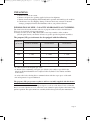
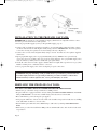
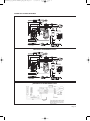
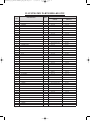
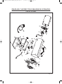
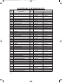
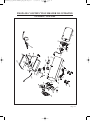
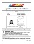
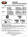
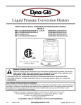
DURAHEAT_FA_SERIES-MANUAL_ENG_FNL:Layout 1
WARRANTY:
07/04/2009
4:55 PM
Page 1
GFA40 / GFA50A / GFA100A / GFA150A
SERVICE AND LIMITED WARRANTY
GHP Group, Inc., warrants this product to be free from defects in materials and components
for one (1) year from the date of first purchase, provided that the product has been properly
installed, operated and maintained in accordance with all applicable instructions. To make a
claim under warranty the Bill of Sale or cancelled check must be presented.
This warranty is extended only to the original retail purchaser. This warranty covers the cost of
part(s) required to restore this heater to proper operating condition and an allowance for labor
when provided by a GHP Group, Inc., Authorized Service Center. Warranty part(s) MUST be
obtained through authorized dealers of this product and/or GHP Group, who will
provide original factory replacement parts. Failure to use original factory replacement parts
voids this warranty. The heater MUST be installed by a qualified installer in accordance with all
local codes and instructions furnished with the unit.
This warranty does not apply to parts that are not in original condition because of normal wear
and tear, or parts that fail or become damaged as a result of misuse, accidents, lack of proper
maintenance or defects caused by improper installation. Travel, diagnostic cost, labor, transportation and any and all such other costs related to repairing a defective heater will be the
responsibility of the owner.
TO THE FULL EXTENT ALLOWED BY THE LAW OF THE JURISDICTION THAT GOVERNS THE
SALE OF THE PRODUCT; THIS EXPRESS WARRANTY EXCLUDES ANY AND ALL OTHER
EXPRESSED WARRANTIES AND LIMITS THE DURATION OF ANY AND ALL IMPLIED WARRANTIES, INCLUDING WARRANTIES OF MERCHANTABILITY AND FITNESS FOR A PARTICULAR PURPOSE TO ONE (1) YEAR FROM THE DATE OF FIRST
PURCHASE PRICE OF THE PRODUCT AND GHP GROUP INC., PRODUCTS SHALL NOT BE
LIABLE FOR ANY OTHER DAMAGES WHATSOEVER INCLUDING INDIRECT, INCIDENTAL OR
CONSEQUENTIAL DAMAGES.
Some states do not allow a limitation on how long an implied warranty lasts or an exclusion or limitation of incidental or consequential damages, so the above limitation on implied warranties, or
exclusion or limitation on damages may not apply to you.
This warranty gives you specific legal rights, and you may also have other rights that vary from
state to state.
Contact GHP Group, Inc., for consumer information, technical assistance and to obtain
replacement parts at 1-877-447-4768. You will need to provide the following information when
communicating with the help desk:
• Heater type and model number
• Serial Number
• Description of the part or problem
GHP Group, Inc., Skokie, IL 60076-4034
Phone: 1-877-447-4768
DURAHEAT_FA_SERIES-MANUAL_ENG_FNL:Layout 1
07/04/2009
4:55 PM
Page 2
PROPANE CONSTRUCTION HEATER
USER’S INSTRUCTION MANUAL
Duraheat GFA40 (40,000 BTU/HR, FORCED - AIR)
MODELS: GFA50A (30,000/50,000 BTU/HR, FORCED - AIR)
GFA100A (70,000/100,000 BTU/HR, FORCED - AIR)
GFA150A (120,000/150,00 BTU/HR, FORCED - AIR)
CSA 2.14a-2007, ANSI Z83.7a-2007
GENERAL HAZARD WARNING:
FAILURE TO COMPLY WITH THE PRECAUTIONS AND INSTRUCTION PROVIDED
WITH THIS HEATER, CAN RESULT IN DEATH, SERIOUS BODILY INJURY AND
PROPERTY LOSS OR DAMAGE FROM HAZARDS OF FIRE EXPLOSION, BURN,
ASPHYXIATION, CARBON MONOXIDE POISONING, AND/OR ELECTRIC SHOCK.
ONLY PERSONS WHO CAN UNDERSTAND AND FOLLOW THE INSTRUCTIONS
SHOULD USE OR SERVICE THIS HEATER.
IF YOU NEED ASSISTANCE OR HEATER INFORMATION SUCH AS AN
INSTRUCTION MANUAL, LABELS, ETC. CONTACT THE MANUFACTURER.
RETAIN THIS INSTRUCTION MANUAL FOR FUTURE REFERENCE
2009-04 Rev.1
DURAHEAT_FA_SERIES-MANUAL_ENG_FNL:Layout 1
07/04/2009
4:55 PM
Page 3
TABLE OF CONTENTS
• Introduction & Specifications . . . . . . . . . . . . . . . . . . . . . . . . . . . . . . . . . . . . . . . . . . . . .
2
• Product Features . . . . . . . . . . . . . . . . . . . . . . . . . . . . . . . . . . . . . . . . . . . . . . . . . . . . . . .
3
• General Safety Instructions . . . . . . . . . . . . . . . . . . . . . . . . . . . . . . . . . . . . . . . . . . . . . . .
• Unpacking Heater . . . . . . . . . . . . . . . . . . . . . . . . . . . . . . . . . . . . . . . . . . . . . . . . . . . . . .
• Size & Capacity Of Propane Cylinders . . . . . . . . . . . . . . . . . . . . . . . . . . . . . . . . . . . . . .
• Installation To The Propane Gas Tank . . . . . . . . . . . . . . . . . . . . . . . . . . . . . . . . . . . . . .
• Refilling The Propane Gas Tank . . . . . . . . . . . . . . . . . . . . . . . . . . . . . . . . . . . . . . . . . . .
• Leak Checking & Location Heater . . . . . . . . . . . . . . . . . . . . . . . . . . . . . . . . . . . . . . . . .
• Lighting & Shutdown Instructions . . . . . . . . . . . . . . . . . . . . . . . . . . . . . . . . . . . . . . . . .
• Test Firing Heater & Storage . . . . . . . . . . . . . . . . . . . . . . . . . . . . . . . . . . . . . . . . . . . . .
3
4
4
5
5
6
6
7
• Troubleshooting . . . . . . . . . . . . . . . . . . . . . . . . . . . . . . . . . . . . . . . . . . . . . . . . . . . . . . . .
7
• Replacement Parts List . . . . . . . . . . . . . . . . . . . . . . . . . . . . . . . . . . . . . . . . . . . . . . . . . .
9
• Wiring Diagrams . . . . . . . . . . . . . . . . . . . . . . . . . . . . . . . . . . . . . . . . . . . . . . . . . . . . . . .
Illustrated Parts Breakdown - GFA40 / GFA50A . . . . . . . . . . . . . . . . . . . . . . . . . . . .
PROPANE CONSTRUCTION HEATER ILLUSTRATED : GFA40
8
9
/ GFA50A . . . . . . . . . . . . . . . . . 10
Illustrated Parts Breakdown - GFA100A / GFA150A . . . . . . . . . . . . . . . . . . . . . . . . . 11
PROPANE CONSTRUCTION HEATER ILLUSTRATED: GFA100A
• Warranty Information
/ GFA150A . . . . . . . . . . . . . . 12
WARNING: FIRE, BURN, INHALATION, AND EXPLOSION HAZARD, KEEP SOLID
COMBUSTIBLES, SUCH AS BUILDING MATERIALS, PAPER OR CARDBOARD, A
SAFE DISTANCE AWAY FROM THE HEATER AS RECOMMENDED BY THE
INSTRUCTIONS.
NEVER USE THE HEATER IN SPACES WHICH DO OR MAY CONTAIN VOLATILE OR
AIRBORNE COMBUSTIBLES, OR PRODUCTS SUCH AS GASOLINE, SOLVENTS,
PAIN THINNERS, DUST PARTICLES OR UNKNOWN CHEMICALS.
WARNING: NOT FOR HOME OR RECREATIONAL VEHICLE USE.
Page 1
DURAHEAT_FA_SERIES-MANUAL_ENG_FNL:Layout 1
07/04/2009
4:55 PM
Page 4
Dura Heat Propane Forced Air Construction Heaters
The heater is designed and approved for use as a construction heater under ANSI Z83.7., CSA2.14
It is hard to anticipate every use which may be made of this heater. CHECK WITH YOUR LOCAL
FIRE SAFETY AUTHORITY IF YOU HAVE QUESTIONS ABOUT APPLICATIONS.
Other standards govern the use of fuel gases and heat producing products in specific applications.
Your local authority can advise you about these.
IMPORTANT: Read this user's manual carefully and completely before trying to operate or
service this heater. Improper use of this heater can cause serious injury or death from fire,
explosion and carbon monoxide poisoning.
This is a direct-fired forced-air construction heater for either indoor construction or outdoor use.
Its intended use is primarily the temporary heating of buildings or structures under construction,
alteration or repair. All the products of combustion generated by the heater are forced through the
heater and released into the area being heated. This heater operates at approximately 98%+ combustion
efficiency but still produces a small amount of carbon monoxide. Humans can tolerate small
amounts of carbon monoxide for short periods. Carbon monoxide can build up in a heated space and
failure to provide adequate ventilation could result in poisoning or death.
WARNING: Not for use with ductwork.
SPECIFICATIONS:
Model No.
GFA40
GFA50A
GFA100A
GFA150A
40,000 BTU/hr
-
30,000 BTU/hr
50,000 BTU/hr
70,000 BTU/hr
100,000 BTU/hr
120,000 BTU/hr
150,000 BTU/hr
Cylinder Pressure
Cylinder Pressure
Cylinder Pressure
Cylinder Pressure
5psig
5psig
5psig
5psig
11” W.C
11” W.C
11” W.C
11” W.C
Electrical Input
120V, 60Hz, 1 Ø
120V, 60Hz, 1 Ø
120V, 60Hz, 1 Ø
120V, 60Hz, 1 Ø
Amperage
Load
0.68amps
0.65amps
0.7amps
0.7amps
Fan
Unload
Load
3550rpm
3000rpm
3570rpm
3300rpm
3580rpm
3300rpm
3580rpm
3300rpm
0.16”
0.16”
0.16”
0.11”
Input Rating
Type of Gas
Gas Supply Pressures
to Regulator Maximum
Minimum (for purpose
of Input Adjustment)
Manifold Pressure
Gas Consumption
Ignition
Spark Gap
Propane
1.9lbs/hr
Piezo/Manual Spark
Propane
1.4lbs/hr
2.3lbs/hr
Continuous Spark
Size (L x W x H)
18.1” x 8.1” x 15.3”
18.1” x 8.1” x 15.3”
Weight
13.7lbs/14lbs
(6.2kg/6.35kg)
14.3lbs (6.48kg)
Propane
3.3lbs/hr
4.6lbs/hr
Continuous Spark
25” x 12.8” x 16”
25” x 9” x 16.9”
25” x 11.6” x 17.3”
21.5lbs/21lbs/20.8lbs
(9.75kg/9.5kg/9.4kg)
Propane
5.6lbs/hr
7.0lbs/hr
Continuous Spark
25” x 9” x 16.9”
21.2lbs (9.6kg)
Page 2
DURAHEAT_FA_SERIES-MANUAL_ENG_FNL:Layout 1
07/04/2009
4:55 PM
Page 5
GENERAL SAFETY INSTRUCTIONS:
Accidents are always tragic especially because so many of them could have been prevented with
little care and judgment. There are some basic good practices, we hope you will follow for safe
use of your heater.
IMPORTANT SAFETY INFORMATION:
• Children should be carefully supervised, when they are in the area.
• Always maintain proper clearance from combustible materials. Minimum clearance from combustibles. Side - 24”; Top - 36”; Front - 72”. Floor -noncombustible.
• Heater must be placed on level and stable surface.
• Never place anything including clothes or other flammable items on the heater.
• The appliance area shall be kept clear and free from combustible materials, gasoline and other
flammable vapours and liquids.
• Do not modify or operate a heater which has been modified.
• Adequate clearance for accessibility and for combustion & ventilation air supply must be maintained at all times when the heater is operating.
• Service and repair should be done by a qualified service person. The heater should be inspected
before each use and at least annually by a qualified person. More frequent cleaning may be
required as necessary. Do not service while hot or operating.
• Never connect heater to an unregulated gas supply.
• The heater is shipped from the factory for LP(Propane) gas. This heater is for use with
propane gas only, do not convert heater to any other gas. Installation must conform to local
codes or, in the absence, with the standard for the Storage and Handling of Liquefied
Petroleum Gases ANSI/NFPA NFPA 58 and the Natural Gas and Propane Installation Code
CSA B149.1
• The minimum and maximum inlet pressures to the regulator from the gas tank are 5 psi and bottle
pressure, respectively. Use only the regulator & hose assembly provided with the heater. Inspect
the regulator/hose assembly prior to each use of the heater. If there is excessive abrasion or wear,
or hose is cut, replace with regulator/hose assembly listed on the parts list prior to using this
heater.
• Gas supply connections should be checked using a 50/50 solution of liquid dish soap and never use
a flame to check for gas leaks.
• The electrical connection & grounding must comply with National Electrical Code.
ANSI/NFPA 70 or in Canada CSA C22.1, Canadian Electrical Code, Part 1. Use only a properly
grounded three (3) prong receptacle.
• Do not restrict inlet or outlet by any means. The flow of combustion and ventilation air is not to be
obstructed.
• Forced air heaters should not be directed toward any propane or gas container within 20 feet of the
exit nozzle. The heater should also be located at least 6 feet away from any propane gas container
(regulations in Canada are 10 feet).
• The propane cylinder supply system must be arranged to provide for vapour withdrawal from the
operating cylinder.
WARNING: Motor and fan must be running before lighting, during operation and at shutdown, in
order to prevent a flame-out condition which could result in personal injury or property damage.
PRODUCT FEATURES:
Page 3
• Portable, Stable & Fully Assembled
• 100% Safety Shutoff System
• Wind Resistant & Rain Protected
• Adjustable Input Ratings
• Continuous Spark Ignition or Piezo Electric Spark Ignition
DURAHEAT_FA_SERIES-MANUAL_ENG_FNL:Layout 1
07/04/2009
4:55 PM
Page 6
UNPACKING:
1. Remove heater from carton.
2. Remove all protective packing applied to heater for shipment.
3. Retain cartons and packaging material until unit is operated and found in good condition.
4. Check heater for any shipping damage. If heater shows any external or internal
damage, promptly inform dealer/distributor where you purchased heater.
INFORMATION ON SIZE * CAPACITY OR PROPANE GAS CYLINDERS:
The chart below shows the number and size of propane tanks needed to run this heater.
*Less gas is vaporized at lower temperatures.
You may need two or more 100 pound tanks or one larger tank in colder weather.
(See the parts list for your model of heater to get the specified regulator assembly.)
The propane (LP) gas tank must also be equipped with the following:
Temperature
(°F) At tank
40,000-50,000 BTU/h
Above 32°F
20°F
32°F
10°F
-10°F
-20°F
Number of Tanks
100,000 BTU/h
150,000 BTU/h
1 - 20lb
2 - 100lb
2 - 100lb
1 - 20lb
3 - 100lb
3 - 100lb
1 - 20lb
1 - 20lb
2 - 20lb
1 - 100lb
2 - 100lb
3 - 100lb
Use Larger Tank
Use Larger Tank
2 - 100lb
3 - 100lb
Use Larger Tank
Use Larger Tank
• A collar to protect the Propane gas valve.
• A shutoff valve terminating a Propane gas cylinder valve outlet as specified in the
American National Standards for Compressed Gas Cylinder Valve Outlets and Inlet
Connections.
• A safety relief valve having direct communications with the vapor space of the tank.
• An arrangement of vapor withdrawal.
The propane (LP) gas pressure regulator and hose assembly supplied with this heater
must be used without alteration.
The hose assembly shall be visually inspected prior to each use of the heater. If it is evident that
there is excessive abrasion or wear, or the hose is cut, it must be replaced prior to the heater being
put into operation. The replacement hose assembly shall be that specified by the manufacturer.
Page 4
DURAHEAT_FA_SERIES-MANUAL_ENG_FNL:Layout 1
07/04/2009
4:55 PM
Page 7
INSTALLATION TO THE PROPANE GAS TANK:
IMPORTANT: You must use a propane/LP gas supply cylinder that is compatible with the connection device provided with the hose and regulator.
1. Provide propane/LP supply system (see Propane/LP Supply, page 4).
2. Connect fuel gas fitting hose/regulator assembly to propane LP tank(s). Turn fuel fitting counterclockwise into threads on tank. Tighten firmly using a wrench. IMPORTANT: Position regulator
so that hose leaving the regulator is in a horizontal position (see Figure 1)
3. Connect hose to heater inlet. Tighten firmly using a wrench. You must use the regulator supplied
with heater.
4. Open propane/LP supply valve on propane/LP tank(s) slowly. NOTE: If not opened slowly,
excess flow device in regulator may stop gas flow. If this happens, close propane/LP supply valve,
wait one minute (or until you hear a click) and open again slowly.
5. Check all connections for leaks. Apply a 50/50 solution of liquid dish soap and water to gas joints.
Bubbles forming show a leak that must be corrected.
6. Close propane / LP supply valve before attempting to repair connection.
WARNING: Purging and filling of LP gas tanks must be performed by personnel who has
been thoroughly trained in accepted LP gas industry procedures. Failure to follow these
instructions may result in explosion, fire, severe personal injury, or death.
REFILLING THE PROPANE GAS TANK:
ALL NEW CYLINDERS MUST BE PURGED BEFORE THE FIRST FILLING.
• Turn heater gas valve knob and gas tank valve to OFF position.
• Propane tank valve equipped with the old style fitting has LEFT HANDED THREADS. Turn POL
fitting CLOCKWISE to loosen. Protect POL fitting when disconnected from tank.
• Have tank filled by your local Propane gas supplier.
• Some propane tanks have a bleed-off valve. This valve should be inspected for leaks after each filling
of the tank. Turn clockwise to close the valve.
• Fasten full Propane tank and connect POL fitting to tank valve by turning COUNTERCLOCKWISE.
• With heater gas valve knob still in the OFF position, turn ON tank valve and check for leaks with
soap solution.
Page 5
DURAHEAT_FA_SERIES-MANUAL_ENG_FNL:Layout 1
07/04/2009
4:55 PM
Page 8
Propane is safe to use when properly handled. Careless handling of the Propane gas tank could result
in fire and/or an explosion. Therefore:
• Always keep tank/cylinder securely fastened in an upright position.
• Avoid tipping tank on its side when connected to a regulator since this may cause damage to
diaphragm in regulator.
• Handle valves with care.
• Never connect an unregulated Propane tank to construction heater.
• Do not subject Propane tank to excessive heat.
• Tightly close the gas shutoff valve on the Propane tank after each use.
• The POL fitting must be protected when disconnected from the propane tank.
• Never store a Propane gas tank inside a building or in the vicinity of any gas burning appliance.
THE DISCONNECTED TANK MUST NEVER BE STORED IN A BUILDING, GARAGE
OR ANY OTHER ENCLOSED AREA.
LEAK CHECKING:
Check all gas connections with a soap solution to be sure they are tight and leak proof.
• The installation of your heater must meet all local codes and/or gas utility requirements or, in the
absence of local codes, with the Storage and Handling of Liquefied Petroleum Gases,
ANSI/NFPA 58 and the Natural and Propane Installation Code, CSA B149.1.
• The minimum clearances to combustible construction: Side - 24”; Top - 36”; Front - 72” must be
maintained at all times.
• The hose assembly should be visually inspected prior to each use of the heater. If it is evident that
there is excessive abrasion or wear, or the hose is cut, it must be replaced prior to the heater being
put into operation.
• The replacement hose assembly shall be that specified by the manufacturer (See page 11 for part
numbers).
LIGHTING INSTRUCTIONS:
WARNING: Motor and fan must be running before lighting, during operation and shutdown, in
order to prevent a flame-out condition which could result in personal injury or property damage.
1.
2.
3.
4.
5.
Connect power cord to a properly grounded three (3) prong 120V, 60Hz, single phase receptacle.
Turn gas valve knob clockwise to OFF position.
Wait five (5) minutes to clear any gas. Then smell for gas, if you don't smell gas, go to next step.
Turn gas supply ON by turning Propane tank valve counterclockwise.
Push in and turn gas control knob counterclockwise to “LOW/IGN”. This will light the burner. If
needed, keep pressing control knob until the burner lights and keep depressing and turning from
OFF to LOW/IGN on Piezo electric spark models. (“HIGH/IGN”: In case of GFA40)
6. Keep the valve knob depressed for at least 30 seconds after lighting the burner. After 30 seconds
release valve knob.
7. If burner does not stay lit, repeat the lighting procedure.
8. When burner is lit, turn gas valve knob counterclockwise to desired setting. (All models, except
GFA40 has only one heat setting)
Page 6
DURAHEAT_FA_SERIES-MANUAL_ENG_FNL:Layout 1
07/04/2009
4:55 PM
Page 9
SHUTDOWN INSTRUCTIONS:
Shutoff Heater:
WARNING: Motor and fan must be running before lighting, during operation and at shutdown, in
order to prevent a flame-out condition which could result in personal injury or property damage.
Turn gas valve knob clockwise to OFF position.
Turn gas supply OFF by turning Propane tank valve clockwise to close.
Disconnect the power cord once the heater has cooled to ambient temperature.
TEST FIRING HEATER:
Test fire your construction heater, following the lighting instructions applicable to the gas control
system employed. Leak test all gas connections with soap solution. Soap bubbles indicate gas leakage. DO NOT use a match or flame to test for gas leaks.
STORAGE: Never store a Propane gas tank inside a building or in the vicinity of any gas or
oil burning appliance. When the Propane tank is not disconnected from the construction heater, the
gas tank and heater must be stored outdoors in a well ventilated area, out of the reach of children. If
for any reason the heater is to be stored indoors, the tank must be disconnected and stored outdoors
in a well ventilated area out of reach of children, in accordance with the standard for the the Storage
and Handling of Liquefied Petroleum Gases, ANSI / NFPA 58 and CSA B149.1, Natural Gas and
Propane Installation Code. The plastic tank valve plug supplied with your tank must be tightly
installed when the tank is disconnected from the heater.
MAINTENANCE INSTRUCTIONS:
1. Turn unit off, allow heater to fully cool and disconnect propane hose before performing any
Maintenance functions. Unplug the unit from the 120V receptacle.
2. Keep unit clean and keep the inside of the torpedo housing debris free.
3. Have unit checked by a qualified technician at least once a year, preferably prior to the heating season.
TROUBLESHOOTING:
PROBLEM
Fan does not turn
when electrical connection is made.
Heater will not fire.
Heater quits while
running.
POSSIBLE CAUSE
1. No electric power to heater.
2. Fan blade contacts inside of heater housing.
3. Fan blade(s) bent
4. Fan motor defective.
1. No spark at ignitor.
2. Improper spark gap.
3. Bad electrode.
1. Internal temperature too high causing limit switch
to shut down operation.
2. Damaged Control Valve.
3. Dust or debris build-up inside of heater.
CORRECTIVE ACTION
1. Check current to electric outlet. If voltage is correct, check power cord and extension cord for
cuts and extension cord for cuts and breaks.
2. Be sure that housing is not damaged. Make sure
there are no obstructions to the fan.
3. Straighten blade(s) to match others.
4. Replace motor.
1. Check ignitor wire. Re-attach or tighten if loose.
Check Spark module. Replace if necessary.
2. Set gap to 0.16”
3. Replace Spark Plug.
1. If the heaters output is restricted, internal temperature becomes too high. Move heater away from
any obstructions.
2. Replace Control Valve.
3.Clean inside of heater.
Always be sure to follow proper maintenance procedures, by cleaning the heater once per
month during regular usage, and check spark gap at least once per season.
Page 7
DURAHEAT_FA_SERIES-MANUAL_ENG_FNL:Layout 1
07/04/2009
4:55 PM
Page 10
WIRING DIAGRAMS:
CONTINOUS SPARK MODELS GFA100A/150A
CONTINOUS SPARK MODELS GFA50A
PIEZO/MANUAL SPARK MODELS GFA40
Page 8
DURAHEAT_FA_SERIES-MANUAL_ENG_FNL:Layout 1
07/04/2009
4:55 PM
Page 11
ILLUSTRATED PARTS BREAKDOWN
ITEM
NO.
DESCRIPTION
QTY.
GFA40
PART NUMBER
GFA50A
1
SHELL IN ASSY
1
2304818
2304818
2
NOZZLE
1
2304829
2304942
1.1
3
3.1
4
5
5.1
6
7
7.1
8
8.1
9
10
11
11.1
11.2
11.3
12
12.1
12.2
12.3
13
13.1
14
15
16
17
18
18.1
18.2
19
20
20.1
21
22
22.1
23
24
24.1
25
26
27
SCREW
FRAME HOLDER
SCREW
THERMAL SWITCH BRACKET
THERMAL SWITCH
SCREW
NOZZLE NUT
SPARK PLUG ASSY
SCREW
THERMOCOUPLE ASSY (1130/1474-425L)
SCREW
TUBING ASSY
OUT SHELL
HANDLE ASSY
SCREW
SCREW
NUT
MOTOR SUPPORT
BOLT
BOLT
SLEEVE
MOTOR ASSY
MOTOR FAN
MOTOR BRACKET
GUARD FAN
POWER CORD ASSY
CONNECTOR INLET
CAPACITY
SCREW
NUT
KNOB
BASE LOWER
SCREW
HEIGHT CONTROLLER
BASE ASSY
SCREW
HEIGHT CONTROL SCREW
VALVE BRACKET
SCREW
VALVE
LEAD WIRE ASSY
28
SPARK MODULE
PCB ASSY
29
REGULATOR & HOSE ASSEMBLY
28.1
Page 9
SCREW
5
1
3
1
1
2
1
1
1
1
1
1
1
1
1
1
1
1
1
1
1
1
1
1
1
1
1
1
1
1
1
1
4
1
1
6
1
1
4
1
1
1
1
1
1
2001086/2001355
2304819
2001355
2304819
2001086/2001355
2001355
2201373
2201563
2304826
2001154
2304578
2201375
2001086/2001355
2304885
2001086/2001355
2304830
2304814/2305403
2101447/2305462
2001086/2001355
2001077
2000384
2304823
2001332
2001333
2304949
2305909
2304821
2304824
2304828/2305411
2201368
2304831
2201372
2001200
2001145
2101451/2305466
2304816/2305407
2001086/2001355
2304817/2305409
230481/2305405
2001086/2001355
2001327/2305467
2304624
2001142
2304820(CK-890SL-AI(A))
2201371
N/A
2201369
2001086/2001355
5002199/5002540(TYQ-9C-LL516-00)
2304826
2001154
2304578
2201375
2001355
2304885
2001355
2304830
2304921/2315312
2101447
2001355
2001077
2000384
2304823
2001332
2001333
2304949
2304547
2304821
2304937
2304828
2101670
2304831
2201372
2001200
2001145
2101451
2304925
2001355
2304927
2304923
2001355
2001327/2304510
2304624
2001356
2304932(K-890D-A6)
2201371
2201391
2201369
2001355
5002614(TYQ-C-LL516-00)
DURAHEAT_FA_SERIES-MANUAL_ENG_FNL:Layout 1
07/04/2009
4:55 PM
Page 12
PROPANE CONSTRUCTION HEATER ILLUSTRATED
GFA40 / GFA50A
Page 10
DURAHEAT_FA_SERIES-MANUAL_ENG_FNL:Layout 1
ITEM
NO.
1
1.1
2
3
3.1
4
5
5.1
6
7
7.1
8
8.1
9
10
11
11.1
11.2
11.3
12
12.1
13
13.1
14
15
16
16.1
16.2
17
18
19
19.1
19.2
20
21
21.1
22
23
23.1
24
25
25.1
26
27
28
29
29.1
30
30.1
32
Page 11
07/04/2009
4:55 PM
Page 13
ILLUSTRATED PARTS BREAKDOWN
DESCRIPTION
SHELL IN ASSY
SCREW
NOZZLE
FRAME HOLDER
SCREW
THERMAL SWITCH BRACKET
THERMAL SWITCH
SCREW
NOZZLE NUT
SPARK PLUG ASSY
SCREW
THERMOCOUPLE ASSY (1130/1474-425L)
SCREW
TUBING ASSY
OUT SHELL
HANDLE ASSY
SCREW
SCREW
NUT
MOTOR SUPPORT
BOLT
MOTOR ASSY
MOTOR FAN
MOTOR BRACKET
GUARD FAN
BACK PRESSURE SWITCH
SCREW
NUT
POWER CORD ASSY
CONNECTOR INLET
CAPACITY
SCREW
NUT
KNOB
BASE LOWER
SCREW
HEIGHT CONTROLLER
BASE ASSY
SCREW
HEIGHT CONTROL SCREW
VALVE BRACKET
SCREW
VALVE
LEAD WIRE ASSY
SPARK MODULE
PCB ASSY
SCREW
CORD WRAP
SCREW
REGULATOR & HOSE ASSY
QTY.
1
5
1
1
3
1
1
2
1
1
1
1
1
1
1
1
1
1
1
1
2
1
1
1
1
1
2
2
1
1
1
1
1
1
1
4
1
1
6
1
1
4
1
1
1
1
1
2
4
1
PART NUMBER
GFA100A
GFA150A
2304929
2001355
2304829
2304930
2001355
2304826
2201373
2001154
2304578
2201392
2001355
2304885
2001355
2304946
2304922
2101447
2001355
2001077
2000384
2304823
2001332
2304548
2304936
2304938
2304939
2305976
2000596
2001145
2101673
2304831
2201390
2000496
2001145
2101451
2304926
2001355
2304928
2304924
2001355
2304928
2304924
2001142
2304929
2001355
2304944
2304931
2001355
2304826
2201563
2001154
2304945
2201393
2001355
2304885
2001355
2304947
2304922
2101447
2001355
2001077
2000384
2304823
2001332
2304548
2304936
2304938
2304939
2305976
2000596
2001145
2101673
2304831
2201390
2000496
2001145
2101451
2304926
2001355
2304928
2304924
2001355
2304928
2304924
2001356
2201371
2201371
2304933(K-890SL-A6(A))
2201391
2201369
2001355
N/A
2101423
2304934 (K-890D-A6 (B))
2201391
2201369
2001355
2101423
2101423
5002758&5002721 (TYQ-6E1-LL38-00 500275&5002721 (TYQ-6E1-LL38-00)
DURAHEAT_FA_SERIES-MANUAL_ENG_FNL:Layout 1
07/04/2009
4:55 PM
Page 14
PROPANE CONSTRUCTION HEATER ILLUSTRATED
GFA100A / GFA150A
Page 12