1
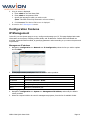
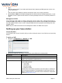
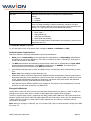
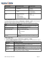
WBSn-2400
Outdoor Wi-Fi Base Station
Quick Start Guide
Contents
Introduction ...................................................................................................... 3
WBSn-2400 Pre-Installation Checklist ............................................................... 3
Installation and Set-up ...................................................................................... 7
Installing the WBSn-2400-S base station...................................................................... 7
Wind Loading Considerations ................................................................................... 8
Connecting Power and DATA ................................................................................... 8
Accessing the Wavion Management Interface............................................................... 9
Configuration Features ............................................................................................. 10
IP Management ........................................................................................................ 10
Management VLAN ............................................................................................... 11
Setting up your base station ..................................................................................... 11
Virtual AP (VAP).................................................................................................... 11
Authentication Combinations ................................................................................. 12
Encryption Methods .............................................................................................. 12
Radio configuration (basic) .................................................................................... 13
VLAN configuration ............................................................................................... 13
QoS (Quality of Service) Packet Priority .................................................................. 14
Wireless Associations ............................................................................................ 14
ACS (Online, Offline) ............................................................................................. 15
Glossary ........................................................................................................... 16
FCC Notice to Users and Operators
This equipment has been tested and found to comply with the limits for a Class B digital device, pursuant to Part 15 of the FCC Rules.
These limits are designed to provide reasonable protection against harmful interference when the equipment is operated in a
commercial environment. This equipment generates, uses, and can radiate radio frequency energy and, if not installed and used in
accordance with the instruction manual, may cause harmful interference to radio communications. Operation of this equipment in a
residential area is likely to cause harmful interference, in which case the user will be required to correct the interference at his own
expense. If this equipment does cause interference to radio or television reception, which can be determined by turning the equipment
off and on, the user is encouraged to correct the interference by using one of the following measures:
•
Reorient or relocate the receiving antenna.
•
Increase separation between the equipment and receiver.
•
Connect the equipment to an outlet on a circuit different from that to which the receiver is connected.
•
Consult the dealer or an experienced radio/TV technician.
Changes or modifications to this unit not expressly approved by the party responsible for compliance could void the user’s authority to
operate the equipment.
Note: This device complies with part 15 of the FCC Rules. Operation is subject to the following two conditions: (1) This device may not
cause harmful interference, and (2) this device must accept any interference received, including interference that may cause undesired
operation.
R&TTE Compliance Statement
This equipment (ETSI-models only) complies with all the requirements of DIRECTIVE 1999/5/CE OF THE EUROPEAN PARLIAMENT AND
THE COUNCIL of March 9, 1999 on radio equipment and telecommunication terminal Equipment and the mutual recognition of their
conformity (R&TTE).
Copyright © Wavion Wireless Networks 2011
Introduction
This document is intended to help you set up and configure your WBSn-2400-O or WBSn-2400-S base
station, using the online Setup wizard.
Note: Throughout this document, unless specified otherwise, the use of the product name WBSn-2400
refers to both the WBSn-2400-O and WBSn-2400-S base stations.
WBSn-2400 Pre-Installation Checklist
The following checklist covers all the procedures and equipment that you need to acquire and assemble,
prior to beginning the installation and configuration procedures. Ensure that you check this list carefully,
before beginning any of the procedures described later in this Guide.
Warning
Only experienced installation professionals who are familiar with local building and safety codes and,
wherever applicable, are licensed by the appropriate government regulatory authorities should install
outdoor units and antennas.
Failure to comply with this may void the WBSn-2400 product warranty and may consequently expose the
end user or Service Provider to legal and financial liabilities.
Wavion and its resellers or distributors are not liable for injury, damage or regulation violations associated
with the installation of Outdoor Units or antennas
Check contents of package
WBSn-2400-O
•
•
•
•
•
•
•
•
•
WBSn-2400-O base station unit (Omni)
PoE injector unit
3 antennas
Post-clamp
Two steel bands
4 screws, each with attached spring and flat washers
Iron security cable
Waterproof sealing tape for IP67 (band to sealing rubber)
Plastic cap and cap cover
WBSn-2400-S
•
•
•
•
•
•
•
WBSn-2400-S unit (Sector)
PoE injector unit
Post-clamp
Two steel bands
4 screws, each with attached spring and flat washers
Iron security cable
Plastic cap and cap cover
•
The WBSn-2400 should only be installed using the antennas provided
as part of the original package.
Ensure that the USB port on the base station unit is properly sealed.
Warning
WBSn-2400 Quick Start Guide
•
Page 3
Additional equipment and tools required for installation
•
•
•
•
•
Ethernet cable (outdoor CAT5e 4-pair data cable, with RJ45 connectors)
Note: Maximum cable length -- 100 meters
Ground cable
Portable PC
Lightning protection
1”-6” diameter pole (on which to mount the unit)
Ensure a safe and secure environment
Connect the PoE injector to the unit using only a straight Ethernet cable.
Warning
Follow these guidelines to
ensure safe operation of the
WBSn-2400 base station:
Do not use crossed cables between the PoE injector and the unit!
•
•
•
•
•
•
•
•
Do not touch or move the antennas while the unit is switched on.
Make sure the antennas are connected when operating the radio or
attempting to transmit data, otherwise, the radio may be damaged.
Do not hold the antenna close to or touching any exposed parts of the
body, especially the face or eyes, while transmitting.
The use of wireless devices on airplanes is governed by the Federal
Aviation Administration (FAA). (US only)
The use of wireless devices in hazardous locations is limited to the
constraints posed by the safety directors of such environments.
The use of wireless devices in hospitals is restricted to the limits set
forth by each hospital.
Do not operate a portable transmitter near unshielded blasting caps or
in an explosive environment.
The Wavion WBSn-2400 must be used only with Wavion-approved
components and antennas.
Note:
The Federal Communications Commission (FCC) with its action in ET Docket 96-8 has adopted a safety
standard for human exposure to RF electromagnetic energy emitted by FCC certified equipment. Proper
operation of the Wavion WBSn-2400 according to the instructions found in this manual, results in user
exposure that is substantially below the FCC recommended limits.
To ensure optimal performance, select the location for the equipment using the following
guidelines:
• The antenna should be directed towards the area intended to be covered, with maximum possible lines
of sight for client locations. Generally speaking, the higher the placement of the antenna, the better the
link quality achievable. For WBSn-2400-SCT, the coverage zone is 120° wide.
• The location of the unit should enable easy access for installation and testing.
• When installing in locations where other devices exist that operate in the same frequency range, ensure
that recommended distances are adhered to.
• The ideal height at which a base station should be installed is 3 meters above the rooftops of the
buildings within the coverage zone.
• The omni-directional unit should be installed at the highest point of a metal pole. This is to ensure that
there is no interference caused by the close proximity of the unit to the metal. Where this is not
possible, the unit should be kept at least 1 meter from the metal pole.
• Keeping the maximum distance possible from an RF radiating source is recommended.
WBSn-2400 Quick Start Guide
Page 4
Preparing the installation site
Only experienced installation professionals who are familiar with local building and safety codes and are
licensed, wherever applicable, by the appropriate government regulatory authorities, should install outdoor
units and antennas.
Warnings
How to prepare the
site:
Grounding best
practices, using a data
protection device
Do not modify the construction of this product. Modifying the operating frequency
or enhancing the transmit output power through the use of external amplifiers or
other equipment is illegal.
This device is for outdoor or indoor use on the condition that operation of this
device causes no harmful interference to authorized radio stations. This device
shall not influence aircraft security and/or interfere with legal communications. If
this device is found to cause interference, the operator of this equipment shall
cease operating this device immediately.
• Ascertain the existence of potential posts or poles to which a base station
could be attached. Consider the axis of the post, its placement, and whether
extenders are required.
• Follow the appropriate electrical and building codes to ensure safe and
durable wiring.
• The length of the Ethernet cable connecting the unit to the network device
(PC, switch, router, and so on) should not exceed 100 meters. There is no
limitation on the length of the cable connecting the PoE to the unit, as long
as the combined length of the cables connecting the network device to the
PoE and the PoE to the unit does not exceed 100 meters.
1. Position the protection device as close to the building entrance as possible.
2. Attach a 10 AWG grounding cable to the ground point on the data protection
device.
3. Attach the other end of the grounding cable to the grounding bar of the
building.
Grounding indoors injector by Network Protection Unit
WBSn-2400 Quick Start Guide
Page 5
Grounding best
practices, using a data
protection device
(continued)
Grounding outdoors injector by Network Protection Unit
Connecting Antennas (for WBSn-2400-O only)
Note: The antennas should only be connected once the installation procedure has been successfully
completed.
How to connect the
antennas:
Warnings
Screw each of the three antennas into the three N-type connectors on the
WBSn-2400base station unit.
• In order for the WBSn-2400 to work properly, all three antennas must be
connected.
• Only connect the unit to the power supply once all the antennas are
connected.
• Use caution when connecting the antennas. Undue haste can damage the
unit.
• Do not screw in the antenna when holding its top section, or you may
damage the antenna.
Antenna Sealing
The following procedure describes how to correctly seal the antennas against moisture.
• It is important to carefully read this procedure and perform all the steps, to
Caution
ensure maximal moisture protection.
• Use high quality sealing material to ensure IP-67 compliant protection
against dust and water.
How to seal the
antennas:
1. After the antenna is connected, use the supplied isolation tape to cover the NType connectors and the lower part of the antennas.
2. Cut 18 cm of the attached splicing tape.
3. Stretch and wrap the tape in an even, half overlapping manner around the
antenna and N-Type connector. Cover this with a layer of vinyl plastic tape.
Safety instructions and information
Please ensure that you read and understand the following safety information. Ensure that you
carefully read and follow all instructions in this manual, and heed all warnings.
Warnings
It is illegal to modify the construction of this product. Modifying the operating
frequency or enhancing the transmit output power through the use of external
amplifiers or other equipment is specifically disallowed by the
"Telecommunications Act.
There is a risk of personal injury or death if the WBSn-2400 antennas are close to
electric power lines.
By nature of the outdoor installation, you may be exposed to hazardous
environments and high voltage. Use extreme caution when installing the system.
WBSn-2400 Quick Start Guide
Page 6
Warnings
All servicing should be referred to qualified service personnel only. There are no
user-serviceable parts inside. Servicing is required when the apparatus has been
damaged in any way.
This apparatus must be properly grounded.
Do not open the unit – risk of electric shock.
Any change or modification not expressly described in this manual or approved by
the manufacturer could void your authority to operate this equipment.
The WBSn-2400 should only be installed using the antennas that were provided
as part of the original package.
A minimum distance of 40cm should be kept from the WBSn-2400 antenna when
the system is in operation.
Only UL-listed parts and components should be used for installation.
To maintain Overvoltage (Installation) Category II, install a suitable surge
suppressor device in the branch circuit to limit expected transients to Overvoltage
Category II values. The limits are based on IEC60664 and are also located in
Table 2H of UL60950 (for mains 110V, the transient rating is 1500V).
Installation and Set-up
The following section describes the installation and configuration procedures for your WBSn-2400-O or
WBSn-2400-S base station, that will enable the establishment of a basic set-up.
Further information regarding configuration procedures and information will be available in the WBSn-2400
User Guide.
Installing the WBSn-2400-S base station
Prior to performing the procedures described in this section, ensure that you have read all the information,
and followed all instructions and safety precautions in the Pre-Installation Checklist.
To install WBSn-2400-S:
1. Decide the manner in which the post-clamp will be attached to the post, whether horizontally or
vertically.
Note: If you wish to install WBSn-2400-S on a horizontal plane, you need to include special extenders in
your order.
Example: Horizontal post-clamp
WBSn-2400 Quick Start Guide
Page 7
2. Slide the steel bands into the appropriate side slots of the post clamp.
Note: For a thinner post, the steel bands should be threaded through the inner slots, and for a wider
post, through the outer slots.
3. Attach the post-clamp to the post, and close and tighten the steel bands.
4. If you are installing the WBSn-2400-S on a vertical post, attach the WBSn-2400-S unit to the postclamp, with the screws and washers. Tighten the screws using a ratchet key, set at 13 mm, and proceed
to Step 6.
5. If you are installing WBSn-2400-SCT on a horizontal post, select the direction in which the base station
unit should point on the horizontal plane prior to continuing with the installation.
6. Once you have determined the correct direction, connect the two extenders to the post clamp.
Attach the WBSn-2400-SCT base station unit and connected extenders to the base station unit.
WBSn attached with extenders
7. As you tighten the screws, verify that the tilt and direction of the base station unit are correct for the
coverage area required.
Note: In an urban setting, with a high-placed installation, a slight downwards tilt (approximately 8-10
degrees) will help reduce noise and interference.
8. For extra security, thread the iron cable through the corner hole on the post-clamp, and the middle hole
on the WBSn-2400-SCT unit, securing it with the Caribena provided.
Note: This will provide extra physical security for the WBSn-2400-SCT unit.
Wind Loading Considerations
The Wavion WBSn-2400 weighs between approximately four kilograms, including all mounting hardware.
When the Wavion WBSn-2400 is mounted on a pole, the sail area of the WBSn-2400 is approximately 0.11
m2. The Wavion WBSn-2400 can load a pole with a maximum load of 3400 Newton in wind conditions of 264
km/h (165 mph).
You should evaluate the static and dynamic load bearing capabilities for each assembly and installation
individually.
Connecting Power and DATA
The following describes how to apply power and data to the WBSn-2400 base station.
Prior to connecting power to WBSn-2400, ensure that you have read and performed all instructions in the
pre-installation checklist.
The Wavion WBSn-2400 is equipped with two ports.
•
Use the ETH port to connect the PoE cable.
•
The USB port is for engineering purposes only. Ensure that the USB port is properly sealed with a
plastic cap.
WBSn-2400 Quick Start Guide
Page 8
Please also note the following:
You must always install an external grounding wire. Make sure you have completed grounding
before you connect power to the WBSn-2400.
Warnings
Note:
This is not a mid-span powered device. Do not attempt to daisy-chain PoE devices.
National Electrical Codes (NEC) Article 800 requires the use of an Agency Listed (UL/CSA)
Building Entrance Protector for all power and communications cables entering a building. Article
800 is intended to protect the building and occupants from fires caused by transient voltage
and current surges.
To connect to the data port:
1. Connect a grounding cable to the grounding terminal and tighten the grounding screw firmly. See
Grounding the Data protection device for a connection diagram.
2. Connect the other end of the cable to the nearest grounded metallic body.
3. Ensure that the power is turned off for the designated circuits.
4. Unscrew the plastic cap and the cap cover from the Wavion WBSn-2400.
5. Run a shielded Category 5 Ethernet cable (appropriate for outdoor use) through the cap.
6. Connect one end of the Category 5 cable to the OUT port of the Wavion PoE injector.
7. Connect the other end of the Category 5 Ethernet cable to the ETH port on the Wavion WBSn-2400.
Note: Use a shielded RJ45 8-pin modular plug to terminate the cables at the required length.
8. After connecting the Ethernet cable to the ETH port, close and firmly tighten the plastic cap. This
ensures perfect sealing and IP-67 compliance.
POE port RJ45 Pin Descriptions
Pin
Signal
Color
Description
1
BI_DA+
Orange-White
Bi-directional pair A +, POE GND
2
BI_DA-
Orange
Bi-directional pair A -, POE GND
3
BI_DB+
Green-White
Bi-directional pair B +, POE +55V
4
BI_DC+
Blue
Bi-directional pair C +, POE +55V
5
BI_DC-
Blue-White
Bi-directional pair C -, POE +55V
6
BI_DB-
Green
Bi-directional pair B -, POE +55V
7
BI_DD+
Brown-White
Bi-directional pair D +, POE GND
8
BI_DD-
Brown
Bi-directional pair D -, POE GND
Accessing the Wavion Management Interface
The following procedure describes how to log in to the WBSn-2400 Wavion Management Interface, and from
there enter the Set-up Wizard, and further configuration information.
Note: The interface requires Java to work. Download the latest Java release from www.java.com.
1. In an internet browser, enter the Management IP address of the WBS unit in the URL navigation field
using secure HTTP protocol (https).
• Default IP address: 192.168.1.1
• Default mask: 255.255.255.0
• Default gateway: 192.168.1.254
Note: Currently, Microsoft Internet Explorer and Mozilla Firefox browsers are supported.
WBSn-2400 Quick Start Guide
Page 9
2. A log-in screen is displayed.
a. Enter admin in the User Name field.
b. Enter admin in the password field.
c. Specify the language in which you wish to work.
(Note: This field will be fully functional in a future release.)
d. Click Connect. The Wavion EMS screen is displayed.
3. Proceed to the IP Management section.
Configuration Features
IP Management
In the GUI, use the System page to set up, configure and manage your IP. This page displays basic static
information on the system, including contact details, and IP addresses. Default values and details are
provided, which should be modified, by specifying parameter values according to your network system and
requirements.
Management IP address
1. Navigate to Configuration => Network => IP Configuration, select the line you wish to update
and click Edit.
2. In the popup window, modify the default IP address values provided:
Parameter
Description
IP Address
Change the default IP address
IP Method
Select either Manual or DHCP
Mask
Enter the required network mask
Gateway
Specify the gateway for the Management IP address
MTU
Maximum Transmission Unit
3. Click Apply, at the bottom of the Wavion EMS screen.
4. Navigate to Configuration => System => Management IP Address, and modify the default
values provided.
5. Select the required VLAN to be used for management purposes, from the list of available VLANs.
WBSn-2400 Quick Start Guide
Page 10
6. Either:
Enter the required static IP, and valid static Network Mask, Gateway and DNS parameter values in the
relevant parameters.
or
Enter the DHCP Client Fallback IP Address and Network mask in the relevant parameters.
7. Specify True or False for the Enable management from Wireless Access Interfaces parameter, in order
to enable or block a specific wireless device from having management access. The default parameter is
True.
Management VLAN
The management VLAN enables a separate management channel of data traffic, enabling administrators to
manage the WBSn-2400 traffic over a separate VLAN (that can be linked to a secured SSID) can be selected
from the enabled VLAN list, and, to which is assigned additional security properties and settings than other
available VLANs.
Note: Only one VLAN can be defined as the Management VLAN in the WBSn-2400 system.
Setting up your base station
Virtual AP (VAP)
You can define and set-up a Virtual AP (VAP), as well as viewing the status of any VAPs that were previously
defined.
To define a VAP:
1. Navigate to Configuration => Wireless => VAP.
2. Specify the parameters according to the parameter value definitions in the below table.
Parameter
Description
Name
Name of the VAP
Hidden
Indicates whether these SSID parameters are broadcast to the public, or
hidden, only accessible by authorized users.
WMM Classification
Packet prioritization over Wi-Fi is based on four access categories defined
by the WMM standard:
• Voice traffic
• Video traffic
• Best effort traffic
• Background traffic
A packet sent to the Ethernet interface of the base station is classified as
one of the Access categories. This classification is performed using ToS,
DSCP or VLAN priorities. For information about classification configuration,
please see QoS Packet Priority.
WBSn-2400 Quick Start Guide
Page 11
Parameter
Description
BH SSID
Indicates whether this SSID is configured as a backhaul SSID.
Values:
• Enabled
• Disabled
ACL Group
The ACL (Access Control List) controls who can access the VAP.
A list is created according to specific parameters, and given a unique
name, and will either define an access group (those users permitted VAP
access), or a reject group (those users denied VAP access).
Security Mode
Choose between the following:
• None (Open)
• WEP (shared key)
• WPA (PSK and RADIUS)
• WPA2 (PSK and RADIUS)
For more information about authentication and encryption, please see the
table below this one.
To view the status of a VAP:
To view the status of any or all defined VAPs, navigate to Status => Wireless => VAP.
Authentication Combinations
WBS-2400 allows the following authentication types and combinations.
•
Open (none) and Shared Key are the basic 802.11n authentications. In Shared Key authentication,
the WEP key is used as the shared key. If the VAP is configured to Open + Shared Key, both types of
clients can associate to the WBSn.
•
The WPA authentication automatically presumes that the basic 802.11 authentication is Open. WPA
defines advanced authentications, either PSK (Pre-Shared Key) or RADIUS. The initial keys are
determined during the last phase of the WPA authentication.
•
When RADIUS Authentication is used, the RADIUS server can determine which VLAN belongs to which
user.
Note: WBSn-2400 supports multiple VLAN per VAP.
•
WBSn-2400 enables a VAP that supports both RADIUS and PSK authentication, with the exact method
determined according to the packet that comes from the client. If multiple VLANs are defined over such
a VAP, clients authenticated using PSK are assigned to the default VLAN, while clients authenticated
using RADIUS have their VLAN determined by the RADIUS.
•
Each VAP can have a different RADIUS server configured. This allows for the transportation of several
networks over the same infrastructure of WBSn-2400
Encryption Methods
Legacy 802.11 clients can either connect using the Open authentication (see above), or WEP. In WEP, the
encryption key can be either 40bit or 104bit. In WPA, WBSn-2400 supports TKIP encryption.
In order to support legacy clients, (supporting only WEP), WBSn-2400 enables the TSN (Transient Security
Network) mode, which allows VAPs that support both WEP and TKIP clients. In this case, the broadcast key
is WEP, while the unicast key is either TKIP or WEP, depending on the manner in which the client is
connected to the system.
Note: When you configure a TSN VAP, key #1 is used by TKIP, and you should therefore configure the WEP
key as key #2.
WBSn-2400 Quick Start Guide
Page 12
Security Mode
Authentication Mode
Encryption Mode
None
Open system
None
WEP
•
Shared key
•
•
WEP/40
WEP/104
WPA
•
•
PSK (Pre-shared key)
Radius
•
•
•
TKIP
TKIP+WEP/40
TKIP+WEP/104
WPA2
•
•
•
•
•
PSK (Pre-shared key)
Radius
Mixed mode PSK
Mixed mode Radius
Mixed mode PSK + Radius
•
•
AES
AES + TKIP
Radio configuration (basic)
To configure the radio settings, navigate to Configuration => Wireless => Radio. Select the required
channel bandwidth and specify the parameters, as described in the following table.
Note: Only 2.4 GHz is available for this WBSn release. 5.0 GHz will be available for future releases.
Field
Description
Radio
Specify that the radio waves are operational, or turn them
off for purposes such as a maintenance.
Channel/Frequency [MHz]
Specify the channel/frequency
Wireless System Mode
Specify the wireless system mode:
• Data
• Video Surveillance
• VOIP
• Custom
TX Power
Specify the transmission power between 1-8 (where 8 is the
maximum)
VLAN configuration
1. To specify a new VLAN, navigate to Configuration => Network => Bridge.
2. Expand the VLANs Configuration window, and click Add to configure the VLAN Parameters. A pop-up
box with the following parameters is displayed.
Parameter
Description and values
VLAN ID
This ID should be unique and must be supported by the backbone equipment
that is connected to the WBS through the Ethernet port.
VLAN Name
Edit the VLAN name as required.
Ethernet
Determine whether the VLAN is configured in the Ethernet interface, and define
whether it is tagged or untagged.
VAP 1-6
Determine whether the VLAN is configured in any of the VAP interfaces and
define whether they are tagged or untagged.
3. Scroll back up to the VLANs section, and specify a VAP for the VLAN.
WBSn-2400 Quick Start Guide
Page 13
QoS (Quality of Service) Packet Priority
Wireless Multimedia Extensions (WME), also known as Wi-Fi MultiMedia (WMM), provide basic QoS features
to IEEE 802.11n networks. WMM prioritizes traffic according to four Access Categories (AC):
• Voice
• Video
• Best Effort
• Background
Traffic is prioritized by these access categories, and the implementation defined by the WMM standard.
Traffic is therefore suitable for applications that require QoS over Wi-Fi, (for example, Voice over IP (VoIP)).
Note: In order to allow QoS through the WBSn-2400, both ends of the network (CPE on the wireless side
and the switch/router on the Ethernet side) should support priority tagging. This permits the marking of a
specific packet with a specific priority.
Downlink (data sent from the network to the user), a packet from the wire-line network is received by the
WBSn, and its priority detected. The packet will be prioritized over the air according to WMM AC
prioritization. When the packet reaches the CPE, the CPE passes it to its LAN interface according to the
packet definition.
Uplink (data sent from the user to the network), the CPE will detect the priority (as defined at the CPE) and
will pass the frame with the correct WMM AC characteristics, thus providing the priority classification on the
wireless side.
Wireless Associations
The Wireless associations list is a list of clients that are connected to the base station. You can access this
list by navigating to Status => Wireless => Associations, where the following list parameters are
displayed.
Parameter
Description
IP Address
IP address of the associated station
MAC
MAC (Media Access Control) address of the associated station
SSID
SSID to which the station is associated
RSSI dBm
The RSSI (Received Signal Strength Indicator) power received by the WBSn
base station from the associated station.
TX Rate
PHY Rate (modulation) at which the base station currently transmits to the
associated station
RX Rate
PHY Rate (modulation) at which the associated station currently transmits to
the base station
State
Indicates the status of the station’s connection:
• Connecting
• Associating
• Requesting Authentication
• Connected
Est. Range
Estimated range of client from WBSn
WMM
A value of 'yes' in this field indicates that the associated station supports the
WMM protocol
Auth. Status
Authorization status
Radio
2.4 GHz or 5.0 GHz
PS
Power Save status
11N
Indicates whether the CPE supports 802.11n protocol
WBSn-2400 Quick Start Guide
Page 14
ACS (Online, Offline)
The Automatic Channel Selection (ACS) utilizes an embedded algorithm to scan for the best channel with
which your base station can work, ensuring optimal capacity, minimal interference and maximum
performance.
Offline ACS performs a full scan of the available channels while the system is down, determining which
channels are the best and most interference-free, and prompting you to choose these channels prior to
resuming and reactivating the system .
Online ACS will run in the background while the system is up, checking the available channels, and whether
any of those available are better for use than the channels currently being utilized.
Note: The ACS will be enabled in a future release
Accessing Automatic Channel Selection
1. Select Configuration => Wireless => Radio.
2. Expand the required field (Online ACS or Offline ACS) to specify the parameters, described in the
following table.
Parameter
Description
Offline ACS
Select Channel button
Click to select a specific channel
Scan
Click to scan, then define the following parameter values:
• Optimization mode:
o Throughput
o Range
• Auto Switch
• On
• Off
• Estimate Scan Time (specify)
Stop Scan button
Stops scan
Optimization Value
Specify the application for which the system will choose the best
channel:
• Data
• Video Surveillance
• VOIP
• Custom
(Future feature.)
Number of loops
Indicates the number of times the scan will loop. (Future
feature.)
Online ACS
Parameters to be specified in a future version
WBSn-2400 Quick Start Guide
Page 15
Glossary
Acronym
Description
2P
Two-Phase or Split Phase
2W
Two-Wire
3W
Three-Wire
AC
Alternating Current
ANSI
American National Standards Institute
AWG
American Wire Gauge
C
Celsius
CAT
Category
CCK
Complementary Code Keying
CFR
Code of Federal Regulations
CSA
Canadian Standard Association
dB
Decibels
dBi
Decibels Relative to an Isotropic Radiator
DBPSK
Differential-Binary Phase-Shift Keying
DC
Direct Current
DQPSK
Differential-Quadrature Phase-Shift Keying
DSSS
Direct-Sequence Spread Spectrum
EMC
Electromagnetic Compatibility
EN
IEC standard
ESD
Electrostatic Discharge
FCC
Federal Communications Commission
Hz
Hertz
HPoE
High Power over Ethernet
IEEE
Institute of Electrical and Electronics Engineers
IP67
Ingress Protection Standard
ISTA
International Safe Transit Association
LAN
Local Area Network
Mbps
Megabits Per Second
MHz
Megahertz
MIL-STD
Military Standard
N
Neutral
NEC
National Electrical Codes
NEMA
National Electrical Manufacturers Association
OFDM
Orthogonal Frequency Division Multiplexing
P
Phase
PE
Protective Earth
WBSn-2400 Quick Start Guide
Page 16
PoE
Power over Ethernet
RJ45
Registered Jack 45
RSS
Received Signal Strength
Rx
Receive
RXD
Receive Data
TUV
Technical Inspection Association
Tx
Transmit
TXD
Transmit Data
UL
Underwriters Laboratories
VAC
Voltage (Alternating Current)
VCCI
Voluntary Control Council for Interference
VDC
Voltage (Direct Current)
W
Watts
WBSn-2400 Quick Start Guide
Page 17