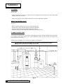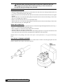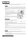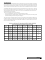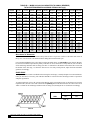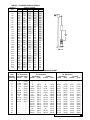
1
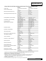
Cat. No. 01882324
Rev. A 12/7/00
DCO#1809
Installation
and
Operating
Instructions
CULLIGAN®
MARK 89 AND 812
AUTOMATIC
WATER CONDITIONER
©2000 Culligan International Company
Printed in USA
Attention Culligan Customer:
Your local independently operated Culligan dealer employs trained
service and maintenance personnel who are experienced in the
installation, function and repair of Culligan equipment. This
publication is written specifically for these individuals and is intended
for their use.
We encourage Culligan users to learn about Culligan products, but
we believe that product knowledge is best obtained by consulting
with your Culligan dealer. Untrained individuals who use this manual
assume the risk of any resulting property damage or personal
injury.
WARNING - Prior to servicing equipment, disconnect
power supply to prevent electrical shock.
This system is not intended to be used for treating water that is
microbiologically unsafe or of unknown quality without
adequate disinfection before or after the system.
Culligan International Company
1 Culligan Parkway
Northbrook, IL 60062
847-205-6000
Installation
and
Operating
Instructions
CULLIGAN®
MARK 89 AND 812
AUTOMATIC
WATER CONDITIONER
Table of Contents
Page
Introduction ............................................................... 2
Specifications ........................................................... 3
Preparation ............................................................... 4
Installation ................................................................ 6
Settings .................................................................. 10
Start-Up Procedure ................................................. 16
Appendix A - Sanitizing Instructions ....................... 17
Wiring Schematic ..................................................... 18
Parts List ................................................................. 20
Introduction
The Culligan® Mark 89 and 812 water softeners are tested and validated by WQA to ANSI/NSF
Standard 44 for the effective reduction of calcium and magnesium (hardness) along with barium
and Radium 226/228*.
SAFE PRACTICES
Throughout this manual there are paragraphs set off by special headings.
NOTICE: Notice is used to emphasize installation, operation or maintenance information which is important, but
does not present any hazard.
Example: NOTICE: The nipple must extend no more than 1 inch above the cover plate.
CAUTION: Caution is used when failure to follow directions could result in damage to equipment or
property. Example:
CAUTION: Disassembly while under water pressure can result in flooding.
WARNING: Warning is used to indicate a hazard which could cause injury or death if ignored. Example:
WARNING! ELECTRICAL SHOCK HAZARD! UNPLUG THE UNIT BEFORE
REMOVING THE TIMER MECHANISM OR COVER PLATES!
SERIAL NUMBERS
The control valve serial number, is on the back of the timer case.
The media tank serial number is on the top edge of the tank side wall.
NOTICE: Do not remove or destroy the serial number. It must be referenced on request for warranty repair or
replacement.
This publication is based on information available when approved for printing. Continuing design refinement
could cause changes that may not be included in this publication.
* Verified utilizing hardness surrogate per ANSI/NSF Standard 44.
2
CULLIGAN® MARK 89 AND 812 WATER CONDITIONER
Specifications
Culligan® Mark 89 and 812 Water Conditioners with Automatic Time Clock or Soft-Minder® Meter
Control Valve
Overall Conditioner Height
Media Tank Dimensions (Dia x Ht)
Salt Storage Tank Dimensions (Dia x Ht)
Exchange Media, Type and Quantity
Underbedding, Type and Quantity
Exchange Capacity
@ Salt Dosage Per Recharge1
Freeboard to Media2
Freeboard to Underbedding3
Salt Storage Capacity
Rated Service Flow @ Pressure Drop
Total Hardness, Maximum
Total Iron, Maximum
Hardness to Iron Ratio, Minimum4
Operating Pressure
Operating Temperature
Electrical Requirements
Electrical Power Consumption, Min/Max
Drain Flow, Maximum5
Recharge Time, Average6
Recharge Water Consumption, Average
89 Model
5-cycle, Reinforced Thermoplastic
51 in
1 29.5 cm
9 x 45 in
23 x 114 cm
16 x 43 in
41 x 109 cm
18 x 43 in
46 x 109 cm
Cullex® Media, 0.7 cu.ft.
Cullex Media, 20 L
Cullsan® Underbed, 20 lb
Cullsan Underbed, 9.1 kg
15,400 gr @ 4.0 lb
998 gr @ 1.8 kg
21,200 gr @ 7.7 lb
1 374 gr @ 3.5 kg
24,200 gr @ 12 lb
1 568 gr @ 5.4 kg
18.9-19.9 in
48-51 cm
39.2 in
99.6 cm
250 lb or 375 lb
114 kg or 170 kg
7.8 gpm @ 15 psi
50 gpg
1 300 mg/L
5 ppm
5 mg/L
8 gpg to 1 ppm
140 mg/L to 1 mg/L
20-125 psi
140-860 kPa
33-120°F
1-50°C
120V/60 Hz
3 Watts/35 Watts
2.0 gpm
7.6 L/pm
80 min
45 gal/4 lb
170 L/1.8 kg
812 Model
5-cycle, Reinforced Thermoplastic
51 in
1 29.5 cm
12 x 45 in
30 x 114 cm
16 x 43 in
41 x 109 cm
Cullex Resin, 1.4 cu. ft.
Cullex Resin, 40 L
Cullsan Underbed, 30 lb
Cullsan Underbed, 13.6 kg
25,000 gr @ 6.0 lb
1 620 gr @ 2.7 kg
35,900 gr @ 12.0 lb
2 326 gr @ 5.4 kg
42,400 gr @ 18.0 lb
2 748 gr @ 8.2 kg
17.5-18.5 in
44-47 cm
38.5 in
98 cm
375 lb
170 kg
8.25 gpm @ 15 psi
75 gpg
1 700 mg/L
5 ppm
5 mg/L
8 gpg to 1 ppm
140 mg/L to 1 mg/L
20-125 psi
140-860 kPa
33-120°F
1-50°C
120V/60 Hz
3 Watts/35 Watts
3.5 gpm
13.5 L/pm
85 min
75 gal/6 lb
284 L/2.7 kg
1
2
3
4
Capacities and corresponding salt dosages pertain to low hardness waters. Capacities given are per recharge
Measured from top of media to top of inlet fitting (backwashed and drained).
Measured from top of underbedding to top of inlet fitting.
Hardness to iron ratio does not apply and total hardness and iron specifications change as follows when
Sofner-Gard® accessory is used: 89 Model - 50 gpg (855 mg/L) total hardness, 10 ppm (mg/L) iron;
812 Model - 75 gpg (1 200 mg/L) hardness, 20 ppm (20 mg/L) iron.
5 Backwash at 120 psi (830 kPa).
6 10 minute backwash, 7 lb (3.2 kg) 89 model or 13 lb (5.9 kg) 812 model salt dosage.
SPECIFICATIONS
3
Preparation
COMPONENT DESCRIPTION
The water conditioner is shipped from the factory in three cartons. Remove all components from their cartons and
inspect them before starting installation.
Control Valve Assembly - Includes the 5-cycle regeneration control valve and timer assembly. A small parts
package contains installation hardware and consumer literature, including an Owner’s Guide and warranty policy.
Media Tank - Includes Tripl-Hull™ media tank complete with Cullex® ion exchange resin, underbedding and
outlet manifold.
Salt Storage Tank Assembly - Includes salt storage container with support plate and Dubl-Safe™ brine refill
valve and chamber.
Bypass Valves - The system installation includes a manually operated bypass valve which enables the softener to
be isolated from the water service lines for maintenance and service and also maintain the continuity of the water
supply when the softener is disconnected.
TOOLS AND MATERIALS
The following tools and supplies will be needed, depending on installation method. Observe all applicable codes.
All Installations
• Safety glasses
• Phillips screwdrivers, small and medium tip
• Gauge assembly (PN 00-3044-50 or equivalent)
• Silicone lubricant (PN 00-4715-07 or equivalent) - DO NOT USE PETROLEUM-BASED LUBRICANTS
• A bucket, preferably light-colored
• Towels
Special Tools
• Torch, solder and flux for sweat copper connections
• Threading tools, pipe wrenches and thread sealer for threaded connections.
• Saw, solvent and cement for plastic pipe connections.
Materials
• Brine line, 5/16” (PN 00-3031-28 or equivalent)
• Drain line, 1/2” (PN 00-3030-82, gray, semi-flexible; or PN 00-3319-46, black, semi-rigid; or equivalent)
• Thread sealing tape
• Pressure reducing valve (if pressure exceeds 125 psi [860 kPa], PN 00-4909-00 or equivalent)
• Pipe and fittings suited to the type of installation
• Water softener salt (rock, solar or pellet salt formulated specifically for water softeners)
APPLICATION
Water quality - Verify that raw water hardness and iron are within limits. Note the hardness for setting the salt
dosage and recharge frequency.
Pressure - If pressure exceeds 125 psi (860 kPa), install a pressure reducing valve (see materials checklist). On
private water systems, make sure the minimum pressure (the pressure at which the pump starts) is greater than 20
psi (140 kPa). Adjust the pressure switch if necessary.
4
CULLIGAN® MARK 89 AND 812 WATER CONDITIONER
CAUTION: The use of a pressure reducing valve may limit the flow of water
in the household.
Temperature - Do not install the unit where it might freeze, or next to a water heater or furnace or in direct
sunlight.
LOCATION
Space requirements - Allow 6-12 inches (15-30 cm) behind the unit for plumbing and drain lines and 4 feet (1.3
metres) above for service access and filling the salt container.
Floor surface - Choose an area with solid, level floor free of bumps or irregularities. Bumps, cracks, stones and
other irregularities can cause the salt storage tank bottom to crack when filled with salt and water.
Drain facilities - Choose a nearby drain that can handle the rated drain flow (floor drain, sink or stand pipe). Refer
to the Drain Line Chart, Table 1 (page 10), for maximum drain line length.
NOTICE: Most codes require an anti-siphon device or airgap. Observe all local plumbing codes and drain
restrictions. The system and installation must comply with all state and local laws and regulations.
Electrical facilities - A 6-foot grounded cord is provided. The customer should provide a 3-prong grounded
receptacle, preferably one not controlled by a switch that can be turned off accidentally. Observe local electrical
codes.
WARNING: ELECTRICAL SHOCK HAZARD! DO NOT REMOVE THE
GROUNDING PRONG! IF THE RECEPTACLE IS DESIGNED ONLY FOR
2-PRONG PLUGS, OBTAIN A 3-PRONG ADAPTER AND GROUND IT
SECURELY TO THE RECEPTACLE. DO NOT USE EXTENSION CORDS.
PREPARATION
5
Installation
PLACEMENT
Refer to Fig. 1.
• Set the media tank on a solid, level surface near water, drain and electrical facilities. Place the outlet (black
coupling) of the tank on the left.
• Set the brine system on a flat, smooth, solid surface as near the media tank as possible.
MOUNT THE CONTROL VALVE
See Fig. 2.
•
•
•
•
Remove and discard the protective covers on the tankcouplings.
Lubricate the o-rings on the tank couplings with silicon lubricant.
Place the control on the tank couplings and press down firmly.
Install the u-clamps on both sides of the control and secure with the screws.
PLUMBING CONNECTIONS
Two methods of connecting the water softener to the plumbing system are available. Shipped with each softener
is a Culligan® Cul-Flo-Valv® bypass valve. If local conditions warrant, you may use the sweat adaptor kits,
PN 00-3314-44 or 00-3314-45.
NOTICE: The Soft-Minder® meter cannot be used with the sweat adaptors.
CAUTION: Close the inlet supply line and relieve system pressure before
cutting into the plumbing! Flooding could result!
FIG. 1
6
CULLIGAN® MARK 89 AND 812 WATER CONDITIONER
FIG. 3
FIG. 2
CAUTION: When making sweat connections, remove all plastic and rubber
components which contact brass or copper. Damage to these components may
result otherwise.
BYPASS VALVE INSTALLATION - TIME CLOCK UNITS ONLY
The bypass valve connects directly to the backplate of the valve with a pair of screws (Fig. 3). To facilitate this
connection, remove the plate by pulling up on the u-clip on the back of the valve. Lubricate all o-rings with silicon
lubricant.
BYPASS VALVE INSTALLATION - SOFT-MINDER® METER ONLY
The Soft-Minder meter is placed between the bypass valve and the control (Fig. 4). Make sure the meter is on the
outlet port of the control. A pair of elongated bolts are packaged with the meter to hold the bypass valve to the
back plate of the control. Lubricate all o-rings with silicon lubricant.
SWEAT ADAPTOR INSTALLATION
The sweat adaptors use a snap ring to hold them to the backplate of the control valve. The back plate will need to
be removed from the valve for this connection. A pair of snap ring pliers, PN 00-5916-09, are needed for this
connection.
FIG. 4
FIG. 5
INSTALLATION
7
CAUTION: When reinstalling back plate to control valve, make sure the u-clip
fully engages the two bottom holes of the bracket (Fig. 5). Secure bracket from
the top with the two mounting screws provided.
CONNECT THE BRINE LINE
Refer to Fig. 7.
• Measure a length of brine line sufficient to reach from the brine tank to the brine fitting and then add four feet
(1.3 meters). Cut both ends squarely and cleanly.
• Remove the brine valve from the brine tank and remove the white nut and insert. Return float rod to its original
position.
• Slip the white nut over one end of the tubing and press the plastic insert into the end of the tubing. Connect to the
brine valve and tighten nut. (Figure 6)
• Remove white nut and insert from wire tie around drain elbow.
• Slip the white nut over one end of the tubing and press the plastic insert into the end of the tubing. Connect to the
brine connection on the valve and tighten nut.
DRAIN LINE CONNECTION
Refer to Table 1, page 11 under the applicable tank size for drain line length and height limitations, and to Fig. 7.
• Remove 1/2” pipe clamp from end of drain elbow.
• Route a length of 1/2” drain line from the drain elbow to the drain.
• Fasten the drain line to the elbow with the clamp.
• Secure the drain line to the drain to prevent its movement during regeneration. A loop in the end of the tube will
keep it filled with water and will reduce splashing at the beginning of each regeneration.
NOTICE: Observe all plumbing codes. Most codes require an anti-siphon device or air gap at the discharge
point!
FILL THE SALT STORAGE CONTAINER
Fill the salt storage container with water until the level reaches about 1 inch above the salt support plate. Pour salt
into the container. Fill to within a few inches of the top.
FIG. 6
FIG. 7
8
CULLIGAN® MARK 89 AND 812 WATER CONDITIONER
SOFT-MINDER® METER CONNECTION
To connect the meter leads, refer to the instructions listed below and the wiring schematic.
• Remove the timer face plate & set it aside.
• Remove the two screws holding the timer cover. Set the timer cover aside.
• Locate the 1/2" hole in the timer plate at the center rear. Remove the plastic plug.
• Slip the meter cable through the hole and toward the circuit board.
• Connect the red wire from the flow meter cable to the common terminal of the lockout switch. Connect the red
wire from the flow meter connection to the normally closed terminal of the lockout switch.
• Connect the flow meter harness to the circuit board. The meter terminal is labeled "METER".
• Locate the strain relief bushing in the parts pack. Place it on the cable at the point of entry to the rear of the
timer plate and push it into the hole.
TABLE 1
9-INCH MODELS
Average Water
Pressure
Height of Drain Discharge Above Floor Upon Which Softener Sets
psi
4 in.
1 ft
2 ft
3 ft
4 ft
5 ft
6 ft
7 ft
8 ft
9 ft
10 ft
kPa
0.1 m
0.3 m
0.6 m
0.9 m
1.2 m
1.5 m
1.8 m
2.1 m
2.4 m
2.7 m
3.1 m
30
56
50
40
30
20
10
2.1
17.1
15.3
12.2
9.2
6.1
3.1
50
112
106
96
86
76
66
56
46
36
26
16
3.5
34.2
32.3
29.3
26.2
23.2
20.1
17.1
14.0
11.0
7.9
4.9
70
143
137
127
117
107
97
87
77
67
57
47
4.8
43.6
41.8
38.7
35.7
32.6
29.6
26.5
23.5
20.4
17.4
14.3
90
153
147
137
127
117
107
97
87
77
67
57
6.2
46.7
44.8
41.8
38.7
35.7
32.6
29.6
26.5
23.5
20.4
17.4
120
159
153
143
133
123
113
103
93
83
73
63
8.3
48.5
46.7
43.6
40.6
37.5
34.5
31.4
38.4
25.3
22.3
19.2
12-INCH MODELS
Average Water
Pressure
Height of Drain Discharge Above Floor Upon Which Softener Sets
psi
4 in.
1 ft
2 ft
3 ft
4 ft
5 ft
6 ft
7 ft
8 ft
9 ft
10 ft
kPa
0.1 m
0.3 m
0.6 m
0.9 m
1.2 m
1.5 m
1.8 m
2.1 m
2.4 m
2.7 m
3.1 m
30
44
38
28
18
2.1
13.4
11.6
8.5
5.5
50
103
97
87
77
67
57
47
37
27
17
7
3.5
31.4
29.6
26.5
23.5
20.4
17.4
14.3
11.3
8.2
5.2
2.1
70
129
123
113
103
93
83
73
63
53
43
33
4.8
39.3
37.5
34.5
31.4
28.4
25.3
22.3
19.2
16.2
13.1
10.1
90
145
139
129
119
109
99
89
79
69
59
49
6.2
44.2
42.4
39.3
36.3
33.2
30.2
27.1
24.1
21.0
18.0
14.9
120
153
147
137
127
117
107
97
87
77
67
57
8.3
46.7
44.8
41.8
38.7
35.7
32.6
29.6
26.5
23.5
20.4
17.4
INSTALLATION
9
Settings
The Mark 89 and 812 Water Conditioners are designed to perform efficiently on a wide range of water supplies.
Before the unit can be recharged and put into service, several settings must be made.
BACKWASH
Backwash, the first step in the recharge cycle, expands and loosens the resin bed, and flushes away accumulated
turbidity. The backwash interval is preset at the factory for 10 minutes, which is adequate for most water supplies.
It is adjustable, however, from 5 to 30 minutes. It is recommended that backwash last long enough so that the
effluent from the drain line is clear. Backwash too long and water is wasted, not long enough and the tank becomes
fouled with sediment.
If backwash time adjustment is needed, refer to Fig. 8.
• Grasp the front cover by the slots and carefully pull forward to
remove cover. Lay the cover aside in a safe place.
• Loosen screw (A) about 1½ turns. DO NOT loosen screw (B).
• Holding the cam gear (located beneath the backwash dial),
rotate the backwash dial (C) until the desired backwash time
lines up with indicator mark (D).
• Tighten screw (A).
NOTICE: Adjusting the backwash time may cause the salt dosage
setting to change. If the salt dosage needs to be
reset, do not tighten screw (A), and refer to the Salt Dosage
section.
TIME OF RECHARGE
Although the need to recharge is determined by the Soft-Minder
control, time of day the conditioner will actually
recharge can be set on the timer mechanism.
FIG. 8
The timer is factory set to recharge about 2:00 a.m., a time when
water usage is at a minimum for most families. If water is drawn
during recharge, hard water will automatically be bypassed to service. If it would be more convenient to have the
water conditioner recharge at a different time of day, the setting may be changed as follows,
referring to Fig. 8.
• Remove the timer cover.
• The position of the peg (H) in relation to the time-of-day dial (J) determines the time when the unit will begin to
recharge.
• Loosen the screw and lift the white time-of-day dial and rotate it until the desired time of recharge is opposite
the peg (H). Please note that whenever the time of recharge is changed, the time-of-day setting may be changed
also.
NOTICE: Whenever the time of recharge is changed the time of day must be reset also.
TIME OF DAY
Upon completing the installation, the timer must be set to the correct time of day. Time of day must also be reset
after any kind of power interruption, such as that caused by an electrical storm. See Fig. 8.
• Determine the correct time of day.
• Grasp the gear (K) and lift straight up (the white time-of-day dial will lift with it). Rotate the gear until the
correct time of day lines up with the pointer (P). The dial is spring-loaded and will return its position when
released. Make sure the teeth mesh.
10 CULLIGAN® MARK 89 AND 812 WATER CONDITIONER
Note that the silver half of the time-of-day dial designates the daytime hours, while the black half designates the
night-time hours.
GUEST CYCLE
An extra recharge can be initiated any time extra soft water is required by pushing the Manual Recharge lever (M)
in the direction of the arrow, then releasing. The unit will still recharge at its regular frequency as determined by
the meter device. On models with meter control, the red button (X) must also be pushed briefly before the recharge
cycle can begin.
SERVICE POSITION
The timer assembly is in the service position when the toothless notch in the cam gear is over the teeth on the idler
gear (L). The timer will return to this position after each recharge (Fig. 8).
TIME CLOCK SETTINGS
To set the Mark 89 and 812 water conditioner for optimal performance, determine the hardness of the water along
with the number of people in the household. Refer to Table 2. Locate the row corresponding to the number of
people in the home and move across to the appropriate hardness column. The number in the shaded region is the
salt dosage. The other number is the frequency of regeneration.
SALT DOSAGE
To set the salt dosage, refer to Fig. 8. Loosen screw (A) and rotate outer dial until the salt dosage dial line up with
the indicator mark (D). Tighten screw (A).
TABLE 2A — CULLIGAN MARK 89 WATER CONDITIONER SALT DOSAGE — FREQUENCY
*Persons
in
Household
0-7
(0-120)
8-14
(121-240)
1
15-21
(241-360)
1
22-28
(361-480)
29-35
(481-600)
36-42
(601-720)
43-49
(721-840)
50-56
(841-960)
2
2
3
3
3
1
Water
Usage
57-63
64-75
Gal. (Litres)
(961-1080) (1081-1280) per day
3
6
2
150(570)
5
5
1
7
1
5
2
6
2
5
3
6
3
8
6
9
6
5
6
6
3
225(850)
5
7
1
5
2
7
2
6
3
9
3
5
6
5
6
6
6
8
6
6
4
300(1135)
5
5
1
7
2
6
3
9
3
5
6
6
6
8
6
9
6
12
6
5
375(1420)
5
5
1
5
2
9
3
5
6
7
6
9
6
12
13
6
6
450(1705)
7
9
2
8
3
5
6
6
6
9
6
12
6
7
525(1990)
5
5
2
5
3
5
6
8
6
12
6
8
600(2270)
5
7
2
5
3
6
6
9
6
6
9
675(2555)
5
9
2
5
3
7
6
13
6
10
750(2840)
5
12
5
9
*In household application, not recommended for over 10 people because of pressure drop limitations.
SETTINGS 11
TABLE 2B — CULLIGAN MARK 812 WATER CONDITIONER SALT DOSAGE — FREQUENCY
*Persons
in
Household
0-7
(0-120)
8-14
(121-240)
15-21
(241-360)
22-28
(361-480)
29-35
(481-600)
36-42
(601-720)
43-49
(721-840)
50-56
(841-960)
2
3
3
3
3
1
Water
Usage
57-63
64-75
Gal. (Litres)
(961-1080) (1081-1280) per day
6
6
2
150(570)
9
7
2
6
8
3
3
11
3
12
6
9
6
9
6
6
3
225(850)
6
7
3
9
13
3
6
7
6
10
6
11
6
14
6
6
4
300(1135)
6
8
3
6
8
6
6
11
6
12
6
17
6
20
6
5
375(1420)
7
1
3
5
3
7
10
6
6
14
6
18
6
20
6
6
450(1705)
8
5
2
9
3
7
6
9
13
6
6
18
6
20
6
7
525(1990)
5
6
2
5
3
8
6
12
16
6
6
20
6
8
600(2270)
5
6
2
6
3
8
6
13
20
6
6
9
675(2555)
6
8
2
6
3
11
6
16
6
6
10
750(2840)
7
9
7
12
20
*In household application, not recommended for over 10 people because of pressure drop limitations.
REGENERATION FREQUENCY
To set the regeneration frequency, push the number of pins in which corresponds to the number located in Table
2 (refer to Fig. 9 and Table 3).
SOFT-MINDER METERING DEVICE
The Mark 89 and 812 Soft-Minder water conditioners are equipped with water meter which regenerates based
upon the water consumption patterns of the household.
TABLE 3 — RECHARGE FREQUENCY
No. Down on
Salt Chart
Pin No. In on
Frequency Dial
Recharge
Frequency
1
1
Every six days
2
1&4
Every three days
3
1, 3 & 5
Every other day
6
All Pins
Every day
FIG. 9
12 CULLIGAN® MARK 89 AND 812 WATER CONDITIONER
GALLONS SETTING
Determine the daily use for the household. Usually 75-100 gallons per day per person is adequate. Using Table 4,
locate the hardness range for your water supply. Move down the column and locate the gallons setting and salt
dosage which best suits the application. Usually two to three days between regenerations yields the best results.
Allow for one half to one days water usage as reserve capacity. Set the salt dosage per the instructions on page 9.
Set the gallons setting on the circuit board. This is done by removing the two screws of the front cover. The circuit
board is located on the upper left hand corner of the back plate. A set of six dip switches on the circuit board
determine the gallons capacity. Refer to Table 5, Figs. 10 and 11 when setting the dip switches. Make sure all
recharge frequency pins are pushed on.
There are two pilot lights located on the circuit board.
• The green pilot light flickers when water is flowing through the water meter.
• The amber pilot light is a latching indicator, when the preset gallons count has passed, the amber light will
illuminate indicating that the unit will regenerate that night.
The softener also has a ten gallon setting to assist the service personnel in trouble shooting the equipment. To
trouble shoot the meter, set the dip switches to the OFF position. Run water into a measured pail. The green light
will flicker. When ten gallons has passed, the amber light will light up. This will help determine if the meter is
properly measuring the gallons count.
TABLE 4A — MARK 89 (0.7FT3) GALLON CAPACITIES TO SIGNAL (RESERVE)
TOTAL WATER HARDNESS IN GRAINS PER GALLON (mg/l)
SALT
DOSAGE
4
5
6
7
8
10
0-10
(0-170)
11-20
(171-340)
21-30
(341-515)
31-40
(516-685)
41-50
(686-855)
51-60
(856-1025)
61-75
(1026-1280)
1300
600
300
(290)
(175)
(230)
NA
NA
NA
NA
1500
600
400
300
(250)
(275)
(183)
(138)
NA
NA
NA
1600
700
400
300
(275)
(238)
(225)
(169)
NA
NA
NA
1700
700
400
300
200
(250)
(275)
(250)
(188)
(190)
NA
NA
1800
800
500
300
200
(200)
(200)
(167)
(200)
(200)
NA
NA
1800
800
500
300
200
200
(210)
(205)
(170)
(203)
(202)
(135)
NA
SETTINGS 13
TABLE 4B — MARK 812 GALLON CAPACITIES TO SIGNAL (RESERVE)
TOTAL WATER HARDNESS IN GRAINS PER GALLON (mg/l)
SALT
DOSAGE
6
7
8
9
10
11
12
13
14
15
16
17
18
0-10
(0-170)
11-20
(171-340)
21-30
(341-515)
31-40
(516-685)
41-50
(686-855)
2500
(270)
2700
(300)
2900
(300)
3000
(350)
3100
(380)
3100
(490)
3100
(580)
3100
(650)
3100
(710)
3100
(740)
3100
(780)
3100
(790)
3100
(780)
1100
(285)
1200
(300)
1300
(300)
1400
(275)
1500
(240)
1500
(295)
1600
(240)
1600
(275)
1600
(305)
1600
(320)
1700
(240)
1700
(245)
1700
(240)
600
(323)
700
(300)
800
(266)
800
(316)
900
(260)
900
(297)
900
(327)
1000
(250)
1000
(270)
1000
(280)
1000
(293)
1000
(296)
1000
(296)
400
(293)
500
(250)
500
(300)
500
(338)
600
(270)
600
(298)
600
(320)
600
(358)
700
(353)
700
(260)
700
(270)
700
(273)
700
(270)
300
(254)
300
(300)
300
(340)
400
(270)
400
(296)
400
(318)
400
(336)
500
(250)
500
(262)
500
(268)
500
(276)
500
(278)
500
(276)
51-60
(856-1025)
61-70
(1026-1200)
71-80
(1201-1370)
81-90
(1371-1540)
91-100
(1541-1700)
NA
NA
NA
NA
NA
NA
NA
NA
NA
NA
NA
NA
NA
NA
NA
NA
NA
NA
NA
NA
NA
NA
NA
NA
NA
NA
NA
NA
300
(200)
300
(233)
300
(258)
300
(280)
300
(298)
400
(213)
400
(225)
400
(235)
400
(240)
400
(247)
400
(248)
400
(247)
300
(178)
300
(197)
300
(212)
300
(225)
300
(236)
300
(244)
300
(248)
300
(254)
300
(256)
300
(254)
300
(160)
300
(169)
300
(176)
300
(180)
300
(185)
300
(186)
300
(185)
300
(126)
300
(131)
300
(132)
300
(131)
NA
200
(188)
200
(189)
200
(188)
Brine Valve "A" Dimension
The brine valve contains a float-actuated safety shut-off device to prevent overflow of the brine tank in the un
likely case of an electrical or mechanical failure during the brine tank refill cycle.
It is recommended that the brine valve float be used as intended, that is, as a secondary, safety shutoff. Remember, the timer mechanism provides the primary refill shut-off. To use the float as a safety shut-off, refer to Table 6
for the salt dosage and brine tank size being used. The "A" dimension is the distance between the filter screen and
the bottom of the float (Fig. 12) when the float stem is in its fully raised position; adjust the float and rubber
grommets accordingly.
RAPID RINSE
The rapid rinse time, which is established when setting the salt dosage, is usually adequate for most installations.
It may be increased, if necessary, but it MUST NEVER be reduced from the salt dosage which is required for
adequate regeneration.
To adjust rapid rinse refer to the section on Salt Dosage. Each one-pound increase in salt dosage will increase
rapid rinse time, the brine valve float will become the primary brine refill shutoff. In this case refer to the correct
Table 7 column for the salt dosage and brine tank size being used, and adjust the "A" dimension accordingly.
SW-1
RUN
TEST
OFF
ON
FIG. 11
FIG. 10
14 CULLIGAN® MARK 89 AND 812 WATER CONDITIONER
TABLE 5 — REGENERATION SCHEDULE
CAPACITY
(GALS.)
10
100
200
300
400
500
600
700
800
900
1000
1100
1200
1300
1400
1500
1600
1700
1800
1900
2000
2100
2200
2300
2400
2500
2600
2700
2800
2900
3000
3100
Salt
Dosage
(Pounds)
3
4
5
6
7
8
9
10
11
12
13
14
15
16
17
18
19
20
SW2
OFF
ON
OFF
ON
OFF
ON
OFF
ON
OFF
ON
OFF
ON
OFF
ON
OFF
ON
OFF
ON
OFF
ON
OFF
ON
OFF
ON
OFF
ON
OFF
ON
OFF
ON
OFF
ON
SWITCH POSITION
SW3
SW4
SW5
OFF
OFF
OFF
OFF
OFF
OFF
ON
OFF
OFF
ON
OFF
OFF
OFF
ON
OFF
OFF
ON
OFF
ON
ON
OFF
ON
ON
OFF
OFF
OFF
ON
OFF
OFF
ON
ON
OFF
ON
ON
OFF
ON
OFF
ON
ON
OFF
ON
ON
ON
ON
ON
ON
ON
ON
OFF
OFF
OFF
OFF
OFF
OFF
ON
OFF
OFF
ON
OFF
OFF
OFF
ON
OFF
OFF
ON
OFF
ON
ON
OFF
ON
ON
OFF
OFF
OFF
ON
OFF
OFF
ON
ON
OFF
ON
ON
OFF
ON
OFF
ON
ON
OFF
ON
ON
ON
ON
ON
ON
ON
ON
SW6
OFF
OFF
OFF
OFF
OFF
OFF
OFF
OFF
OFF
OFF
OFF
OFF
OFF
OFF
OFF
OFF
ON
ON
ON
ON
ON
ON
ON
ON
ON
ON
ON
ON
ON
ON
ON
ON
FIG. 12
160 lb. Brine Tank
"A" Dimension
Secondary (Only)
inches
(cm)
TABLE 6 - "A" DIMENSION CHART
250 lb. Brine Tank
375 lb. Brine Tank
"A" Dimension
"A" Dimension
Secondary
Primary
Secondary
Primary
inches
(cm)
inches
(cm)
inches
(cm)
inches
(cm)
6
7-3/4
9-1/2
1-1/4
13
14-3/4
16-1/2
18-1/4
20
21-3/4
21-1/2
25-1/4
—
—
—
—
—
—
—
—
8
9-3/8
10-7/8
12-1/4
13-5/8
15
16-3/8
17-3/4
19-1/8
20-1/2
21-7/8
23-1/4
24-5/8
26
27-3/8
28-3/4
(15.2)
(19.7)
(24.1)
(28.6)
(33.0)
(37.5)
(42.0)
(46.3)
(51.0)
(55.2)
(59.7)
(64.1)
—
—
—
—
—
—
—
—
(20.3)
(23.8)
(27.6)
(31.1)
(34.6)
(38.1)
(41.6)
(45.1)
(48.6)
(52.1)
(55.5)
(59.0)
(62.5)
(66.0)
(69.5)
(73.0)
—
—
6
7-3/8
8-7/8
10-1/4
11-5/8
13
14-3/8
15-3/4
17-1/8
18-1/2
19-7/8
21-1/4
22-5/8
24
25-3/8
26-3/4
—
—
(15.2)
(18.7)
(22.5)
(26.0)
(29.5)
(33.0)
(36.5)
(40.0)
(43.5)
(47.0)
(50.5)
(54.0)
(57.5)
(61.0)
(64.5)
(68.0)
—
—
6-1/2
7-1/2
8-1/2
9-1/2
10-1/2
11-1/2
12-1/2
13-1/2
14-1/2
15-1/2
16-1/2
17-1/2
18-1/2
19-1/2
20-1/2
21-1/2
—
—
(16.5)
(19.0)
(21.6)
(24.1)
(26.7)
(29.2)
(31.7)
(34.3)
(36.8)
(39.4)
(42.0)
(44.5)
(47.0)
(49.5)
(52.1)
(54.6)
—
—
4-1/2
5-1/2
6-1/2
7-1/2
8-1/2
9-1/2
10-1/2
11-1/2
12-1/2
13-1/2
14-1/2
15-1/2
16-1/2
17-1/2
18-1/2
19-1/2
—
—
(11.4)
(14.0)
(16.5)
(19.0)
(21.6)
(24.1)
(26.7)
(29.2)
(31.7)
(34.3)
(36.8)
(39.4)
(42.0)
(44.5)
(47.0)
(49.5)
SETTINGS 15
Start-Up Procedure
WARNING: FOR PROTECTION, A SANITIZING AGENT HAS BEEN ADDED
TO THE SOFTENER TANK AT THE FACTORY. THIS SANITIZING AGENT
MUST BE FLUSHED OUT BEFORE THE UNIT IS PLACED INTO SERVICE
BY RUNNING AT LEAST 50 GALLONS OF WATER THROUGH THE UNIT
DRAIN.
•
•
•
•
•
•
•
•
•
•
•
•
Close the main supply valve.
Set the bypass valve(s) to bypass.
All faucets in the installation site should be closed.
Direct the drain line discharge into a bucket where flow can be observed.
Plug the unit into a 120 Volt, 60 Hertz, single phase grounded, 3-wire receptacle (or 2-wire receptacle with
grounded 3-prong adapter).
Set the timer to the correct time of day.
Open the main supply valve.
On the timer, push the Manual Recharge lever to the left until it stops.
Slowly shift the Cul-Flo-Valv® bypass toward the "Soft Water" position until water flows. On three-valve
bypass installations, close the bypass valve and open the outlet and inlet valves.
Allow the unit to fill slowly until water flows from the drain line.
When flow to drain is established, open the bypass fully. Watch the drain line discharge for signs of resin. If
resin particles appear, reduce the flow. Increase the flow again when resin no longer appears in the discharge.
When the unit is filled with water, return the timer to the service position.
WARNING: ALTHOUGH NOT NORMALLY NECESSARY, SHOULD YOU NEED
TO DISASSEMBLE ANY PART OF THE CONTROL VALVE OR REMOVE THE
CONTROL FROM THE TANK ASSEMBLY OR ASSOCIATED PLUMBING,
DEPRESSURIZE THE UNIT FIRST CLOSING THE MAIN SUPPLY VALVE,
THEN OPEN A CONVENIENT FAUCET DOWN STREAM FROM THE WATER
CONDITIONER.
During the recharge cycle, hard water will be available to all the lines in the household. Immediately following
recharge, the water to service will be soft.
Because of the volume of water contained in the water heater, the hot water may not be soft for several days. Soft
hot water can be made available almost immediately, however, if the water heater is drained immediately after
recharge and allowed to refill with soft water.
BEFORE LEAVING THE INSTALLATION SITE
Make sure the brine tank is filled with water to the level of the float. Fill the tank with a hose or put the unit into
a full recharge so that the brine refill cycle will fill the tank.
Explain the operation of the softener to the customer. Give the customer a copy of the Owner's Guide and
warranty policy. Make sure the customer knows that there will be new sounds associated with the recharging of
the unit. Advise the customer to periodically check and replenish the salt supply.
Clean up the unit and the installation site, removing any soldering or pipe threading residues from the equipment
with a damp towel.
16 CULLIGAN® MARK 89 AND 812 WATER CONDITIONER
Appendix A - Sanitizing Instructions
A water softener in daily use on a potable water supply generally requires no special attention other than keeping
the salt tank filled. Occasionally, however, a unit may require sanitation under one of the following conditions:
•
•
The unit has stood idle for a week or more (the premises vacant or the residents on vacation).
On private supplies, the appearance of off-tastes and odors, particularly if musty or "rotten egg" (caused by
harmless sulfate-reducing bacteria).
For occasional occurrences, the softener can be sanitized with household bleach as follows.
NOTICE: If the water supply contains iron, regenerate the softener before sanitizing to remove accumulated iron
from the Cullex® resin.
WARNING: HAZARD FROM TOXIC FUMES! CHLORINE BLEACH AND
COMMON IRON CONTROL CHEMICALS MAY GENERATE TOXIC FUMES
WHEN MIXED.
•
IF THE UNIT USES CULLIGAN® SOFNER-GARD™ CHEMICAL OR OTHER COMPOUNDS
CONTAINING SODIUM HYDROSULFITE OR SODIUM BISULFITE, OR ANY OTHER
REDUCING AGENT, DISCONNECT THE DEVICE AND MANUALLY REGENERATE THE UNIT
BEFORE SANITIZING.
•
DO NOT USE THIS PROCEDURE IF THE SOFTENER SALT CONTAINS IRON CONTROL
ADDITIVES.
1.
2.
Remove the brine tank cover and the small cover on the brine valve chamber.
Pour directly into the brine chamber 1 cup (9-inch units) or 2 cups (12-inch units) of common household
bleach (5-1/4% sodium hypochlorite).
Manually start a recharge cycle. Allow the unit to complete the recharge cycle automatically.
3.
If tastes and odors return frequently, even after sanitization, a continuous chlorination system may be needed.
Contact Household Application Engineering for assistance. Also, have the consumer send a sample to a qualified
laboratory for bacterial analysis.
APPENDIX A - SANITIZING INSTRUCTIONS 17
Automatic Clock Timer
Wiring Schematic
18 CULLIGAN® MARK 89 AND 812 WATER CONDITIONER
WIRING SCHEMATIC 19
Timer with Soft-Minder® Meter
Control Valve
20 CULLIGAN® MARK 89 AND 812 WATER CONDITIONER
01-0037-43
01-0037-44
01-0137-03
01-0137-04
00-4498-65
00-4481-26
00-4449-14
00-4481-28
00-4468-35
00-3184-78
01-0130-83
00-4473-87
00-4010-22
00-4457-97
00-4517-01
01-0126-49
01-0126-48
01-0126-47
00-3185-50
00-3183-54
00-4452-21
01-0136-03
00-4452-46
00-4435-59
00-4010-40
00-4452-72
00-4452-44
00-3183-43
00-4486-86
01-0130-31
01-0129-28
00-4486-59
00-3184-55
00-3184-52
01-0083-40
00-4429-21
00-3318-78
00-4444-53
00-4444-52
1
2
‡3
4
‡5
6
‡7
8
9
‡10
11
17
18
20
22
26
27
‡28
29
30
31
32
‡33
34
35
37
38
40
41
42
43
‡44
61
62
63
Control Valve Assembly - Mark 89, TC
Control Valve Assembly - Mark 812, TC
Control Valve Assembly - Mark 89, SM
Control Valve Assembly - Mark 812, SM
Control Valve
Rear Body Plug
O-Ring
Retainer, Rear Body Plug
Drain Elbow Assembly w/O-Ring
Screw
Seal Pack Assembly
Retainer, Drain Elbow
Eductor Port Cover
Gasket
Clamp
Follower
Yoke
Bracket
Screw
Nut
Bellcrank
Drive Motor & Bracket Assembly, 120V/60 Hz
Roll Pin
Roll Pin
Switch Bracket
Barrier
Switch
Washer
Screw
Cam
Spacer
Retaining Ring
Screw
Screw
Control Back Plate
Timer Mechanism, 6 Day, 120V/60 Hz - TC Models
Screw
Strain Relief Adapter
Strain Relief
Description
‡ Recommended Spare Parts
* Not Illustrated
Part No.
Item
00-4429-84
00-3318-48
00-4442-84
00-4015-67
01-0017-84
00-4429-29
00-4022-01
01-0128-09
00-4457-80
01-0046-89
00-3183-83
00-4012-48
00-4452-69
00-3084-38
00-3084-37
00-4432-91
00-3031-93
00-3031-92
00-4479-87
01-0136-06
00-4479-86
00-3084-07
01-0082-55
01-0101-27
00-4460-38
00-4460-39
00-3316-45
00-3316-36
01-0051-30
00-4462-96
00-4462-97
00-4486-87
01-0051-26
01-0079-01
01-0079-02
01-0112-79
00-4029-54
00-4029-55
00-3308-32
64
65
66
67
68
80
81
83
84
85
86
‡98
99
‡100
‡101
102
103
104
‡105
‡106
107
108
120
‡121
‡156
223
*
*
*
*
*
*
*
178
197
157
Part No.
Item
Power Cord
Terminal Strip
Screw
Clip
Screw
Label
Screw
Control Cover
Cover Plate
Cul-Flo Bracket
Screw
Eductor w/O-Rings
Eductor Screen
O-Ring
O-Ring
Connector Brine Line
Nut, PP, 0.312"
Insert, PP, 0.312"
O-Ring
Eductor Sleeve and Eductor Piston Assembly
O-Ring
O-Ring
Meter Mounting Bracket
Circuit Board - 120 Volt
Eductor Nozzle - Blue, 9" Tanks
Eductor Nozzle - Light Brown, 12" Tanks
Backwash Flow Restrictor, #2, Brown, 9" Tanks
Backwash Flow Restrictor, #3, Green, 12" Tanks
Bracket
Decal, Mark 89
Decal, Mark 812
Screw
Noise Suppressor - SM Models
Wire Harness, Circuit Board - SM Models
Wire Harness, Regen. Switch - SM Models
Flow Meter Assembly - SM Models
Cam Wire Harness - TC Models
Cam Wire Harness - SM Models
Hat Screen - SM Models
Description
Control Valve Parts List
CONTROL VALVE PARTS LIST 21
Conditioner Tank & Parts List
Item
1
4
5
6
7
8
9
10
11
12
13
14
15
16
17
18
Part Number
Description
01-0037-55
01-0037-58
01-0042-98
01-0042-99
01-0072-81
P0-2320-07
P0-3339-57
P0-3044-11
01-0072-82
01-0072-83
01-0072-88
01-0021-19
01-0054-50
00-3232-05
01-0072-85
01-0019-46
01-0019-47
00-4445-85
00-4445-46
00-4419-97
00-4446-45
00-4445-83
00-4446-44
00-2202-36
00-2202-22
Tank Assembly, 9" Time Clock, Complete
Tank Assembly, 12" Time Clock, Complete
Replacement Tank, 9" Time Clock, Empty
Replacement Tank, 12" Time Clock, Empty
Outlet Manifold
Inlet Manifold / MP 25
O-Ring / MP 25
O-Ring / MP 25
Inlet Adaptor
Nut, Plastic
Cover Plate
Plate
Gasket
Barrier
Yoke
Cover, 9"
Cover, 12"
Crush Pad, 9"
Crush Pad, 12"
Gasket, Ring, 9"
Gasket, Ring, 12"
Well, 9"
Well, 12"
Liner, 9"
Liner, 12"
22 CULLIGAN® MARK 89 AND 812 WATER CONDITIONER
Quantity
1
1
1
2
1
2
1
1
1
1
1
1
1
1
1
1
1
1
1
1
1
Salt Storage Tank Parts List
Item
—
—
—
†1
2
3
*
*
Part No.
00-4413-90
00-4418-86
00-4418-87
01-0048-70
00-3039-93
00-4010-42
00-3039-80
00-3040-10
00-4413-91
00-3039-75
00-3044-30
00-3044-39
Description
Brine System, 160 lb. Replacement
Brine System, 250 lb. Replacement
Brine System, 375 lb. Replacement
Gold Band
Cover with Band, 250 lb. (114 kg)
Cover with Band, 160 lb. (73 kg)
Cover with Band, 375 lb. (170 kg)
Tank Only, 250 lb. (114 kg)
Tank Only, 160 lb. (73 kg)
Tank Only, 375 lb. (170 kg)
Salt Plate, Plastic, 250 lb. (114 kg)
Salt Plate, Plastic, 350 lb. (159 kg)
* Not Illustrated
† Order by footage required
SALT STORAGE PARTS LIST 23
Brine Valve & Parts List
Item Part Number Description
—
—
1
2
3
‡4
‡5
6
00-4418-88
00-4011-41
00-3031-93
00-3031-92
00-4407-96
00-3084-07
00-4016-22
00-3400-14
7
‡8
9
00-4407-95
00-3325-28
00-2234-35
10
11
12
13
14
‡15
16
17
‡18
19
00-3047-03
00-3047-18
00-4448-73
00-3320-72
00-4446-64
00-4444-96
00-4473-92
00-4477-81
00-3048-04
00-5418-21
00-5418-34
20
00-3045-37
00-4413-92
†
21
*
00-3046-06
00-3184-92
*
00-3306-29
*
*
00-4463-88
00-4463-89
Brine Valve Assembly
Brine Valve Assy., Brine Tank, 160 lb.
Plastic Nut, 5/16-inch
Plastic Insert
Refill Cap
O-ring
Flow Restrictor, No. 5, 0.45 gpm (170 lpm)
Stem Seat Assy., 250 lb. (114 kg) & 375 lb.
(170 kg) (US) & 350 lb. (159 kg) (Canadian)
Refill Body
Hat Screen
Plastic Pipe, 1/4-inch NPT x 35 inches long,
250 lb. (114 kg) & 375 lb. (170 kg) (US) &
350 lb. (159 kg) (Canadian)
Float Retainer (2 required)
Float Weight, Stainless Steel (2)
Float
Screen Top Seal
Filter Screen Cap
Stem Seat
Insert
Air Eliminator Ball
Ball Seat
Float Valve Body with Ball Seat
Float Valve Body with Ball Seat, 150 lb.
Brine Tank
Brine Valve Chamber, 250 lb. (114 kg) &
375 lb. (170 kg) Salt Storage Tank (US)
Brine Valve Chamber, 160 lb. (Shown)
Brine Valve Chamber, 350 lb. (159 kg)
(Canadian)
Cap, Brine Valve Chamber
Screw, Brine Valve Chamber (Canadian)
#10 - 16 x 1/2-inch TRS HD PHIL
Connector Spacer, Brine Valve Chamber
(Canadian)
Screw, St. Steel, Brine Valve Chamber (US)
Nut, St. Steel, Brine Valve Chamber (US)
* Not Illustrated
† Replace with 00-3045-15 and relocate spacer
‡ Recommended Spare Parts
24 CULLIGAN® MARK 89 AND 812 WATER CONDITIONER
Timer & Parts List
Item
Part No.
Description
Item
Part No.
Description
1
2
3
4
5
6
7
8
9
10
11
12
13
†
14
15
16
17
18
19
00-4429-21
00-4482-57
00-4031-54
00-4417-67
00-4413-35
00-4413-38
00-4010-24
00-4045-02
00-4409-32
00-4413-32
00-4409-47
00-4409-28
00-4409-29
00-4477-96
00-4428-85
00-4406-30
00-4031-39
00-4409-35
00-4414-08
00-3354-29
00-4409-43
Mark 89/812 Timer Replacement
Screw, #4-24 x 0.625" Phil.
Screw, #4-24 x 0.312" Oval Hd.
Adjustment Lever
Dial, Salt Dosage
Dial, Backwash
Cam, Notched
Lever, Manual Regeneration
Spring
Gear, Idler
Pin, Retainer
Pin
Wheel, Interval
Screw, #4-40 x 0.750" Rd. Hd.
Screw, #4-40 x 1.625" Lg. Slot
Washer
Spring
O-ring
Screw, #4-24 x 0.250" Pan Hd.
Gear, Gray
Gear, Black
20
21
22
23
24
25
26
27
†28
29
31
32
33
34
†35
‡†36
37
‡38
39
*
*
00-4409-40
01-0013-85
01-0013-84
01-0013-86
00-4409-30
00-4409-31
00-4475-72
00-4421-48
00-4480-04
00-4412-63
00-4442-99
00-4010-23
00-4413-40
01-0017-58
00-3183-32
00-4416-77
00-4459-38
00-4409-34
00-4414-10
00-3300-00
00-3300-01
Pointer, Time of day
Dial, Time of day
Wheel, Time of Regeneration
Decal
Spacer
Switch, Miniature
Screw, #4-24 x 0.875" Phil
Spacer
Spacer
Spring
Decal
Cam, Refill, Backwash
Cam, Backwash
Cam, Fast Rinse
Washer
Switch, Push Button
Plate with Inserts
Motor, Timer
Screw, #4-40 x 0.250" Pan Hd.
Kit, Frequency Wheel, 6-Day
Kit, Frequency Wheel, 7-Day
† Used only for Aqua-Sensor®
‡ Recommended Spare Parts
* Not Illustrated
TIMER PARTS LIST 25