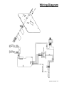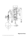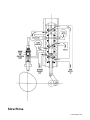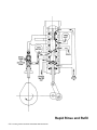
1
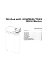
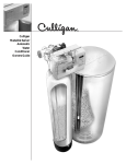
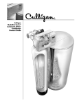
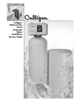
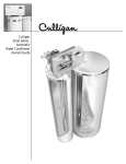
Cat. No. 01-8820-13
Rev. B 12/31/01
DCO-3296
CULLIGAN MARK 100 WATER SOFTENER
SERVICE MANUAL
®
Models from 1998
WARNING: IF INCORRECTLY INSTALLED, OPERATED OR MAINTAINED, THIS PRODUCT CAN CAUSE SEVERE INJURY.
THOSE WHO INSTALL, OPERATE, OR MAINTAIN THIS PRODUCT SHOULD BE TRAINED IN ITS PROPER USE, WARNED OF
ITS DANGERS, AND SHOULD READ THE ENTIRE MANUAL BEFORE ATTEMPTING TO INSTALL,
OPERATE OR MAINTAIN THIS PRODUCT.
CULLIGAN COMPANY
NORTHBROOK, ILLINOIS 60062
©1998 Culligan International Company
Attention Culligan Customer:
The installation, service and maintenance of this equipment should
be rendered by a qualified and trained service technician. Your local independently operated Culligan dealer employs trained
service and maintenance personnel who are experienced in the
installation, function and repair of Culligan equipment. This publication is written specifically for these individuals and is intended
for their use.
We encourage Culligan users to learn about Culligan products, but
we believe that product knowledge is best obtained by consulting
with your Culligan dealer. Untrained individuals who use this manual
assume the risk of any resulting property damage or
personal injury.
WARNING - Prior to servicing equipment, disconnect
power supply to prevent electrical shock.
CULLIGAN MARK 100 WATER SOFTENER
SERVICE MANUAL
®
Table of Contents
Introduction .............................................................. 2
Safe Practices .......................................................... 2
Serial Numbers ........................................................ 2
Specifications ........................................................... 3
Familiarization .......................................................... 4
Service Check Out ................................................... 7
Programming ............................................................ 9
Parts Replacement Guide ...................................... 12
Dimension Charts/Refill Rates ............................... 15
Flow Charts ....................................................... 20-24
Introduction
SAFE PRACTICES
SERIAL NUMBERS
Throughout this manual there are paragraphs set off by
special headings.
The control valve serial number, is on the back of the timer
case.
NOTICE: Notice is used to emphasize installation, operation or maintenance information which is important, but does
not present any hazard.
The media tank serial number is on the top edge of the tank
side wall.
Example: NOTICE: The nipple must extend no more than 1
inch above the cover plate.
CAUTION: Caution is used when failure to follow directions could result in damage to equipment or property.
NOTICE: Do not remove or destroy the serial number. It must
be referenced on request for warranty repair or replacement.
This booklet is designed and organized to assist the service
technician in developing a systematic service call approach
for the Culligan® Mark 100 water softeners.
WARNING: Warning is used to indicate a hazard which
could cause injury or death if ignored.
Included are suggestions on preventive and periodic maintenance, recommended tools for servicing equipment with the
motorized valve, and specific service procedures. Also, technical information on flow rates, settings, critical dimensions,
wiring and flow schematics are included.
Example: WARNING! ELECTRICAL SHOCK HAZARD! UNPLUG THE UNIT BEFORE REMOVING
THE TIMER MECHANISM OR COVER PLATES!
This publication is based on information available when approved for printing. Continuing design refinement could cause
changes that may not be included in this publication.
Example:
CAUTION: Disassembly while under
water pressure can result in flooding.
2 / CULLIGAN MARK 100 WATER SOFTENER SERVICE MANUAL
Specifications
Culligan® Mark 100 Water Conditioners with Time Clock, Aqua-Sensor® Device or Soft-Minder® Meter
Control Valve
Overall Conditioner Height
Media Tank Dimensions (Dia x Ht)
Salt Storage Tank Dimensions (Dia x Ht)
Exchange Media, Type and Quantity
Underbedding, Type and Quantity
Exchange Capacity
@ Salt Dosage Per Recharge1
Freeboard to Media2
Freeboard to Underbedding3
Salt Storage Capacity
Rated Service Flow @ Pressure Drop
Total Hardness, Maximum
Total Iron, Maximum
Hardness to Iron Ratio, Minimum4
Operating Pressure
Operating Temperature
Electrical Requirements
Electrical Power Consumption, Min/Max
Drain Flow, Maximum5
Recharge Time, Average6
Recharge Water Consumption, Average
9” Model
5-cycle, Reinforced Thermoplastic
51 in
1 295 mm
9 x 45 in
229 x 1 143 mm
16 x 43 in
457 x 1 092 mm
18 x 43 in
457 x 1092 mm
Cullex® Media, 0.86 ft3
Cullex Media, 24.5 L
Cullsan® Underbed, 12 lb
Cullsan Underbed, 5.4 kg
16,200 gr @ 4.0 lb
1 050 gr @ 1.6 kg
23,900 gr @ 8.0 lb
1 549 gr @ 3.2 kg
24,700 gr @ 12.0 lb
1 601 gr @ 5.4 kg
16.6-17.6 in
420-450 mm
39.2 in
996 mm
250 lb or 375 lb
114 kg or 170 kg
7.5 gpm @ 15 psi
30 Lpm @ 102 kPa
50 gpg
1 300 mg/L
5 ppm
5 mg/L
8 gpg to 1 ppm
140 mg/L to 1 mg/L
20-125 psi
140-860 kPa
33-120°F
1-50°C
120V/60 Hz
3 Watts/35 Watts
2.0 gpm
8 L/pm
80 min
45 gal
170 L
12” Model
5-cycle, Reinforced Thermoplastic
51 in
1 295 mm
12 x 45 in
305 x 1 143 mm
18 x 43 in
457 x 1 092 mm
Cullex Resin, 1.4 ft3
Cullex Resin, 40 L
Cullsan Underbed, 30 lb
Cullsan Underbed, 14 kg
27,700 gr @ 6.0 lb
1 795 gr @ 3 kg
35,200 gr @ 12.0 lb
2 280 gr @ 5.3 kg
40,300 gr @ 18.0 lb
2 611 gr @ 8.1 kg
17.5-18.5 in
444-470 mm
38.5 in
978 mm
375 lb
170 kg
7.5 gpm @ 15 psi
31 Lpm @ 102 kPa
75 gpg
1700 mg/L
5 ppm
5 mg/L
8 gpg to 1 ppm
140 mg/L to 1 mg/L
20-125 psi
140-860 kPa
33-120°F
1-50°C
120V/60 Hz
3 Watts/35 Watts
3.5 gpm
14 L/pm
85 min
86 gal
325 L
1
2
3
4
Capacities and corresponding salt dosages pertain to low hardness waters. Capacities given are per recharge
Measured from top of media to top of inlet fitting (backwashed and drained).
Measured from top of underbedding to top of inlet fitting.
Hardness to iron ratio does not apply and total hardness and iron specifications change as follows when Sofner-Gard® accessory is used:
9" Model - 50 gpg (855 mg/L) total hardness, 10 ppm (mg/L) iron; 12" Model - 75 gpg (1 200 mg/L) hardness, 20 ppm (20 mg/L) iron.
5 Backwash at 120 psi (830 kPa).
6 10 minute backwash, 7 lb (3.2 kg) 9” model or 13 lb (5.9 kg) 12” model salt dosage at 30 psi (204 kPa).
SPECIFICATIONS /
3
Familiarization
CONTROL
Programming Switches
The Culligan® Mark 100 water softener uses the same power
valve control as in our Culligan Mark 89/812 models. It can
be programmed as either a time clock, Aqua-Sensor® sensing device or Soft-Minder® meter model. Each model has its
own programming parameters which can be set to control
the operation and regeneration of the system. These are
outlined in Table 1.
The circuit board will require the proper setting of the dip
switches in order to function properly.
TABLE 1
FUNCTION
TIME
CLOCK
SOFT-MINDER
METER
AQUA-SENSOR
SENSING
DEVICE
1. Time of Day
YES
YES
YES
2. Time of Regen.
YES
YES
YES
3. Not Used
NO
NO
NO
4. Salt Dosage
YES
YES
YES
5. Backwash Time
YES
YES
YES
6. Brine Rinse Time
YES
YES
NO
7. Hardness Level
NO
YES
NO
8. Gallons Capacity Regeneration Interval
YES
YES
NO
9. Lock/Unlock display
YES
YES
YES
10. Blanking Feature
YES
YES
YES
Switch 1 - Sets the unit in the Run or Test mode.
Switch 2 - Sets the unit for Filter or Softener. (Not activated
for North American units)
Switch 3 - Multiple gallons read out by 10 or 100. (Currently
not used on household systems)
Switch 4 - Sets the tanks for 9” or 12”.
Switch 5 - In the OFF position, the unit will have the
standard Refill cycle. In the ON position, the unit has an
accelerated Refill cycle. (If an accelerated Refill cycle is
chosen, the refill flow control in the brine refill assembly
must be changed to PN 00-4016-23)
Switch 6 - When turned ON, this will allow an immediate
regeneration upon a signal from the Soft-Minder® Meter and
Aqua Sensor® sensing device. When the switch is in the OFF
position, a delayed regeneration will occur.
Switch 7 - In the ON position, the softener will measure in
liters and either French degree’s or German degree’s. In the
OFF position, the conventional English parameters are used.
Switch 8 - Sets the unit to display time as military time or
Standard 12 hour clock.
During the programming stage, the user will be prompted to
enter the appropriate parameter. Refer to Programming, page
9 for further information.
CIRCUIT BOARD
The AccuSoft™ microprocessor circuit board controls every
function of the Culligan Mark 100 water softener. This board
has several unique features which allow it to perform a variety of functions. Familiarization of the board is essential for
a thorough understanding of the softener.
CAUTION: The AccuSoft circuit board must be
handled by its edges to prevent damage to the circuitry. Mishandling of the circuit board will void the
warranty. Keep replacement boards in their special
anti-static plastic bags until ready for use.
4 / CULLIGAN MARK 100 WATER SOFTENER SERVICE MANUAL
FIG. 1
TABLE 2 - DEFAULT CONDITIONS
Switch 9 - When Switch number 7 is turned ON, switch number 9 must be set to either German or French degrees’. If
Switch number 7 is Off, switch number 9 will not be used.
Switch 10 - When turned ON, the softener will regenerate
every third day if a regeneration has not occurred within the
three day interval. (Used only for Aqua-Sensor or Soft Minder
models.)
Auxiliary Connections
Refer to Fig. 1. Aqua-Sensor sensing device connections are
located in the lower area of the board, the Soft-Minder connections are to the left side of the board. Power terminals are
located along with lower mid section of the board. They are
marked from left to right as neutral, motor neutral ground,
and motor common. Connections for the motor homing and
program microswitch are located to the above right of the
power leads. All terminals are clearly marked for easy
installation.
Time of Day
12:00 A.M.
Time of Regeneration
2:00 A.M.
Chlorination
10 min.
Salt Dosage
10 lb., 9”
16 lb., 12”
Backwash Time
Brine Rinse
Hardness
Regeneration Interval
10 min.
71 min., 9”
59 min., 12”
20 GPG
3 days
Display Blanking
Enabled
Display Lock Out
Disabled
Soft-Minder® Systems
Display Blanking
As shipped from the factory, the display of the board will
turn off if there has been no key board activity for a 1 minute
period. To have the display constantly lit, press the STATUS
button until the number 10 icon is lit. Next, press the UP and
DOWN arrows simultaneously. A “d” for disable will
appear in the display. To have the display blank again , press
the UP and DOWN arrows simultaneously. An “E” will
appear in the display .
Display Lockout
The Culligan® Mark 100 control is equipped with a new feature which will allow you to protect the programmed settings
from tampering by unauthorized individuals. When the lockout feature is activated, the only parameter which can be
adusted is the Time of Day.
The microprocessor automatically calculates the gallons of
water which can be treated based upon the salt dosage, water
hardness and tank size. Numeric enunciator 8 will display
the GALLONS TO SIGNAL for regeneration (the portion of
the capacity which is held in reserve is not displayed).
As an option GALLONS TO SIGNAL for regeneration can
be set directly to override the calculation through numeric
enunciator 8. You can increase or decrease the gallons to signal to meet the needs of the application. The conditioner must
cycle through a complete regeneration before the gallon override is saved in the microprocessor. NOTICE: Changing the
capacity will effect the reserve capacity. An INCREASE in
the gallons capacity will DECREASE your reserve capacity.
A DECREASE in the gallons capacity will INCREASE the
reserve capacity.
To activate the lockout feature, press the STATUS button until
the number 9 icon is illuminated. A “U” for unlock will be
displayed. Press the UP and DOWN arrows simultaneously.
A “L” for lock will appear along with an icon of a lock. All
program parameters, except time of day, are now frozen at
their current settings. To disable this feature, press the UP
and DOWN arrows simultaneously.
For units equipped as a Soft-Minder meter, the gallons remaining can be viewed by pressing the STATUS button until
the screen is blank. Press the DOWN arrow until the number
15 icon is illuminated. The display must be multiplied by 10
to determine the actual gallons remaining before the unit calls
for a regeneration. The regeneration will occur immediately
or be delayed until the time of regeneration depending upon
the position of dip switch number 6.
Power Loss
Aqua Sensor® Units
The AccuSoft™ circuit board is equipped with a capacitor,
which in the event of a power outage will maintain all the
programming parameters and time-of-day for up to two full
days.
The Culligan Mark 100 softener, when operating with the
Aqua Sensor sensing device, has a unique brine rinse detection circuitry built into the microprocessor. During the brine
draw/Slow rinse cycle, the Aqua Sensor probe will sense when
the brine solution has rinsed from the tank. It will then automatically shift the control into the Fast Rinse/Refill cycle.
If a power outage lasts for more than 2 days, the control then
resets all default programmed parameters to factory preset
conditions, and the display will flash “8888” for default. The
display will continue to flash until the control is reprogrammed. Default conditions are outlined in Table 2.
To view the length of the last Brine Draw/Slow Rinse cycle,
press the STATUS button until the display is blank. Press the
DOWN arrow until the number 15 icon is illuminated.
FAMILIARIZATION / 5
Regeneration
An immediate regeneration will take place if dip switch number 6 is turned ON and the gallons capacity has reached zero
or if the Aqua Sensor sensing device has sent a signal to the
circuit board. An immediate regeneration will also take place
by pressing the REGEN button twice. The REGEN
enunciator will flash during the regeneration cycle.
A delayed regeneration will take place if dip switch number
6 is turned OFF and the gallons capacity has reached zero or
if the Aqua Sensor sensing device has sent a signal to the
circuit board. A delayed regeneration will also take place if
the REGEN button is pushed once. The REGEN enunciator
will be lit constantly indicating that a regeneration will take
place at the time of regeneration.
If power is lost during a regeneration cycle, the unit will do
one of the following:
1.
If the power loss is less than 2 minutes, the control will
continue in the regeneration cycle when power is
restored.
2.
If the power loss is between 2 minutes and 4 hours, the
control will return to the service position when power is
restored and start a new regeneration cycle.
3.
For power outages greater than 4 hours, the unit will
home itself when power is restored. The unit will then
initiate a full regeneration.
Cycling
The Culligan® Mark 100 control can be indexed through the
various regeneration stages.
1. Press the STATUS button until the display is blank. Push
the UP arrow. An “H” will appear in the display. The
number 11 icon will light up. The control is in the HOME
position.
2. Press the REGEN button twice. The REGEN icon will
light and blink. Push the UP arrow. A “1” will appear. The
unit is now in the BACKWASH position. The numbers to
the right of the colon indicates the time remaining for the
cycle.
3. Press the UP arrow. A “2” will appear in the display. The
control is in the BRINE DRAW/SLOW RINSE cycle.
4. Press the UP arrow. A “3” will appear in the display. The
control is now in the FAST RINSE/REFILL cycle.
5. Press the UP arrow. An “H” will appear in the display.
The unit is in the HOME position. The REGEN
enunciator is no longer blinking.
6. Press the STATUS key twice.
Time-of-Day appears in the display.
Failure Mode
The Culligan Mark 100 control is equipped to detect a motor
or piston which is locked in a frozen position. The AccuSoft™
circuit board will apply power to the motor for 30 seconds. If
there is no change in the motor homing or position switch,
the control will power down for 90 seconds. The circuit board
will repeat this procedure two more times in an attempt to
6 / CULLIGAN MARK 100 WATER SOFTENER SERVICE MANUAL
H 00
I I0
2 53
3 07
H 00
8:00
123
4 5 6 7 8 9 101112
123
4 5 6 7 8 9 101112
123
4 5 6 7 8 9 101112
123
4 5 6 7 8 9 101112
123
4 5 6 7 8 9 101112
REGEN
REGEN
REGEN
AM
remove the obstruction. If no movement has been detected,
the control will permanently power down and a phone icon
will appear in the display. The phone indicates that a service
call is required to fix the control. To return to the service
mode, turn off the power to the unit for 1 full minute and
remove the obstruction to the motor or piston.
Service Check Out
TABLE 3
Board Diagnostic
ACTION
SEGMENT
UP KEY
1
DOWN KEY
2
REGEN KEY
3
STATUS KEY
4
CLOSE HOMING SWITCH
5
CLOSE PROGRAM SWITCH
6
FLOW METER PLUGGED IN
7
AQUA SENSOR PROBE PLUGGED IN
8
WATER FLOW
9 (Fluttering)
DIP SWITCH 1
SOFTWARE VERSION
DIP SWITCH 2
“1111”
DIP SWITCH 3
“2222”
DIP SWITCH 4
“3333”
DIP SWITCH 5
“4444”
DIP SWITCH 6
“5555”
DIP SWITCH 7
“6666”
DIP SWITCH 8
“7777”
DIP SWITCH 9
“8888”
DIP SWITCH 10
“9999”
To enter the board test mode, turn all the switches to the ON
position. All the segments of the board will light until either
a key is depressed, an option is changed or a CAM micro
switch changes position. Pressing one of the keys, closing a
micro switch or turning OFF a dip switch will cause a
different segment to light as outlined in Table 3.
A balanced signal should be applied to the Aqua-Sensor® pin
connector. This can be done with a set of resistors, with a
clean Aqua-Sensor probe and a fully regenerated bed or with
the Aqua-Sensor Tester, PN 01-0079-99.
An unbalanced signal will cause the drive motor to run continuously. A balanced signal will cause the motor to stop.
This test can be used to check the integrity of the Aqua-Sensor probe. If the probe is connected to the board and the drive
motor runs continuously, the probe should be cleaned and
checked.
SERVICE CHECK OUT
/7
Service Check Mode
The service check mode allows one to view the instantaneous flow rate (0.5-10.0 gpm, meter models only), the days since the
last regeneration, the number of regenerations in the past fourteen days and either the gallons remaining or the length of the brine
rinse cycle on Aqua-Sensor® units. To enter the service check mode, follow these steps:
1. Press the STATUS key until the display is blank.
2. Push the DOWN arrow. The number 12 will appear
for Soft-Minder® models only. The display reads the
gallons per minute flow rate.
4 5 6 7 8 9 101112
123
4 5 6 7 8 9 101112 13 1415
123
4 5 6 7 8 9 101112 13 1415
123
4 5 6 7 8 9 101112 13 1415
3. Press the DOWN arrow. The number 13 lights up.
The number in the display indicates the number of
regenerations in the last 14 days.
4. Press the DOWN arrow. The number 14 will light
up. The number in the display indicates the number of
days since last regeneration.
5. Press the DOWN arrow. The number 15 will be
displayed. For Aqua-Sensor models, the display indicates
the length of the BRINE/RINSE cycle. For Soft-Minder
models, the display indicates the gallons remaining
before the unit signals for a regeneration (multiply the
displayed number by 10). This display will not illuminate
for Time Clock models.
8 / CULLIGAN® MARK 100 WATER SOFTENER SERVICE MANUAL
5.0
4
2
123
73
PROGRAMMING
Upon plugging in the Culligan® Mark 100 control, the display will flash 8888. To access the programming mode, press
the status button. Refer to diagrams below for the programming sequence.
1. Plug in.
Press status.
12:00 will appear.
123
Press
2. Press status.
123
Press
3. Press status.
123
Press
4. Press status.
123
Press
5. Press status.
123
Press
6. Press status.
123
Press
7. Press status.
123
Press
8. Press status.
123
Press
9. Press status.
I2:00
Displays flashing
AM
Set Time-of-Day. ALL MODELS.
4 5 6 7 8 9 101112
▲ to increase or
▼ to decrease
2:00
4 5 6 7 8 9 101112
▲ to increase or
▼ to decrease
8
AM
Set Recharge Time.
ALL MODELS. Step 3 is currently not
used.
Set Salt Dosage (3-15 lb for 9”, 5-24 lb for
12”). ALL MODELS.
4 5 6 7 8 9 101112
▲ to increase or
▼ to decrease
I0
Set Backwash Time
(5-40 minutes). ALL MODELS.
4 5 6 7 8 9 101112
▲ to increase or
▼ to decrease
7I
4 5 6 7 8 9 101112
▲ to increase or
▼ to decrease
20
4 5 6 7 8 9 101112
▲ to increase or
▼ to decrease
Set Brine Rinse Time (37-85 minutes for 9”,
35-89 minutes for 12”). TIME CLOCK AND
METER MODELS ONLY.
Set Hardness Level (1-75 gpg for 9”,
1-99 gpg for 12”).
METER MODELS ONLY.
3
Set Regeneration Interval (1-42 days).
TIME CLOCK MODELS ONLY.
Set Gallons To Signal (10-99990).
METER MODELS ONLY (Multiply displayed
number by 10).
L
Set LOCK or UNLOCK feature to prevent
tampering with settings.
E
Set ENABLE or DISABLE feature to allow
constantly illuminated display or a blank
display after 1 minute.
4 5 6 7 8 9 101112
▲ to increase or
▼ to decrease
4 5 6 7 8 9 101112
▲ simultaneously
▼
1 2 3 4 5 6 7 8 9 101112
Press
▲ to change
SERVICE CHECK OUT
/9
10 / CULLIGAN® MARK 100 WATER SOFTENER SERVICE MANUAL
15-3/4
(40.0)
21-3/4
(55.2)
8
12
11-3/8
(26.9)
7-1/2
(19.1)
TOTAL CAPACITY
CAPACITY TO SIGNAL
TOTAL CAPACITY
CAPACITY TO SIGNAL
4-5/8
(11.7)
9-1/4
(23.5)
15-3/4
(40.0)
7-3/4
(19.7)
14-3/4
(37.5)
21-3/4
(55.2)
8
12
11-3/8
(26.9)
7-1/2
(19.1)
3-1/4
(8.9)
150 LB
250 LB
375 LB
INCH(CM) INCH(CM) INCH(CM)
4
SALT
DOSAGE
“A” DIMENSION
TOTAL CAPACITY
CAPACITY TO SIGNAL
TOTAL CAPACITY
CAPACITY TO SIGNAL
TOTAL CAPACITY
CAPACITY TO SIGNAL
1-5
6-10
980
707
903
609
817
590
678
457
613
442
602
406
544
393
HARDNESS
774
522
700
505
546
366
490
354
493
332
445
322
452
305
417
281
387
261
301
244
4,940 2,470 1,647 1,235
3,656 1,828 1,219 914
731
966
631
980
495
637
4,900 2,450 1,633 1,225
3,314 1,657 1,084 813
644
805
823
609
817
526
537
412
522
706
442
700
457
618
387
613
549
406
544
333
494
366
490
300
449
332
445
267
412
305
380
281
353
261
329
244
11-15 16-20 21-25 26-30 31-35 36-40 41-45 46-50 51-55 56-60 61-65 66-70 71-75
3,220 1,610 1,073
2,596 1,298 849
6-10
5,420 2,710 1,807 1,355 1,084
3,656 1,828 1,219 914
731
1-5
HARDNESS
11-15 16-20 21-25 26-30 31-35 36-40 41-45 46-50 51-55 56-60 61-65 66-70 71-75
4,900 2,450 1,633 1,225
3,537 1,949 1,179 1,004
TABLE 4B - CAPACITY, 9” SOFT-MINDER® METER (GALLONS)
9-1/4
(23.5)
150 LB
250 LB
375 LB
INCH(CM) INCH(CM) INCH(CM)
14-3/4
(37.5)
SALT
DOSAGE
“A” DIMENSION
TABLE 4A - CAPACITY, 9” AQUA-SENSOR® SENSING DEVICE (GALLONS)
SERVICE CHECK OUT
/ 11
N/A
18
11-3/8
(28.9)
17-1/4
(43.8)
15-3/4
(40.0)
24-1/2
(62.2)
CAPACITY TO SIGNAL
TOTAL CAPACITY
TOTAL CAPACITY
CAPACITY TO SIGNAL
24-1/2
(62.2)
12
N/A
15-3/4
(40.0)
21-3/4
(56.2)
6
18
7-3/8
(18.7)
17-1/4
(43.8)
11-3/8
(28.9)
5-1/2
(14.0)
150 LB
250 LB
375 LB
INCH(CM) INCH(CM) INCH(CM)
14-3/4
(37.5)
SALT
DOSAGE
“A” DIMENSION
TOTAL CAPACITY
CAPACITY TO SIGNAL
TOTAL CAPACITY
CAPACITY TO SIGNAL
TOTAL CAPACITY
CAPACITY TO SIGNAL
6-10
HARDNESS
6-10
851
578
749
505
766
520
674
454
638
433
562
379
547
371
479
325
426
289
383
260
555
666
644
963
466
646
7,660 3,830 2,553 1,915 1,532 1,277 1,094
5,346 2,673 1,748 1,311 1,018 849
713
6,740 3,370 2,247 1,685 1,348 1,123
4,832 2,416 1,580 1,185 920
767
753
904
958
624
843
564
408
565
851
537
749
486
766
484
674
437
638
395
562
357
547
335
479
286
426
246
383
219
11-15 16-20 21-25 26-30 31-35 36-40 41-45 46-50 51-60 61-70 71-80 81-90 91-99
4,520 2,260 1,507 1,130
3,495 1,748 1,143 857
1-5
958
650
843
568
HARDNESS
7,660 3,830 2,553 1,915 1,532 1,277 1,094
5,200 2,600 1,733 1,300 1,040 867
743
963
649
11-15 16-20 21-25 26-30 31-35 36-40 41-45 46-50 51-60 61-70 71-80 81-90 91-99
6,740 3,370 2,247 1,685 1,348 1,123
4,542 2,271 1,514 1,136 908
757
1-5
TABLE 4D - CAPACITY, 12” SOFT-MINDER® METER (GALLONS)
21-3/4
(56.2)
150 LB
250 LB
375 LB
INCH(CM) INCH(CM) INCH(CM)
12
SALT
DOSAGE
“A” DIMENSION
TABLE 4C - CAPACITY, 12” TIME CLOCK AND AQUA-SENSOR® SENSING DEVICE (GALLONS)
Parts Replacement Guide
Familiarize yourself with the replacement procedures and
component parts thoroughly before attempting any repair.
1.
WARNING! DISCONNECT ALL ELECTRICAL
POWER TO THE UNIT BEFORE SERVICING. BYPASS
THE UNIT AND RELIEVE SYSTEM PRESSURE
BEFORE ATTEMPTING REPAIR.
WARNING! ELECTRICAL SHOCK HAZARD.
WILL CAUSE PERSONAL INJURY OR DEATH.
2.
Remove the timer cover by twisting the four, quarter turn
Phillips screws located on the top of the lever.
Remove the power, microswitch and motor leads from
the board .
Circuit Board
To replace the AccuSoft™ circuit board, refer to the parts list
and proceed as follows:
WARNING! TO PREVENT DAMAGE TO THE
LEADS, PULL THE LEADS BY GRIPPING THE
CONNECTING TERMINALS ONLY.
3.
FIG. 2
12 / CULLIGAN® MARK 100 WATER SOFTENER SERVICE MANUAL
Remove the five screws holding the board to the timer
case (Fig. 2).
FIG. 3
Remove the new circuit board from its protective wrap
and install the circuit board by reversing the steps above.
CAUTION: Do not touch any surfaces of the circuit board. Electrical static discharges can damage
the board. Handle the board by its edges only.
Eductor Piston Assembly
Follow the instructions for the drive motor through step 5,
then continue as follows:
1.
While holding the drive motor free of the backplate,
firmly pull the eductor piston housing assembly from
the valve body.
Follow the circuit board replacement instructions through Step
2 and proceed as follows:
2.
The eductor piston can be removed from the housing at
this time. Inspect and replace any damaged o-rings.
1.
Remove the drive motor cam switches (Fig. 3).
3.
2.
Remove the snap ring holding the drive motor cam to
the cam shaft with snap ring pliers. Lift the cam off the
shaft.
Reverse the procedure for reassembly. NOTICE: The
eductor sleeves are unique to the softener, filter and
Super S™ controls. Refer to the parts list for the proper
component.
3.
Remove the retaining clip from the bell crank assembly
(Fig. 4).
Drive Motor Assembly
Eductor Assembly
Refer to the parts list and the following instructions:
4.
Using a 1/4" hex driver, remove the bolt above the
eductor piston assembly.
1.
Remove the three eductor plate mounting screws and
the eductor plate (Fig. 5).
5.
While holding firmly to the motor housing, remove the
two Phillips head screws. The motor should be free of
the backplate.
2.
The eductor screen can be removed by lifting it from the
eductor body.
3.
6.
Reverse the procedure to reassemble. Refer to the
wiring diagram (page 19) for the correct wire lead
placement.
The eductor body can be removed by grasping one of
the projections with the pliers and gently pulling upward.
4.
Reverse the procedure to reassemble. Be certain that the
replacement eductor body contains the correct eductor
nozzle.
Seal Pack Assembly
Follow the instructions for the drive motor through step 5,
then continue as follows:
1. While holding the drive motor free of the backplate,
firmly put the seal pack assembly from the valve body.
2.
Lightly lubricate the o-rings of the replacement seal pack
with silicone grease. (Use only silicon grease; petroleumbased lubricants will cause degradation of the rubber
components).
3.
Reverse the procedure for reassembly. IMPORTANT:
DO NOT twist the seal pack upon insertion. This may
cut or crimp the outer o-rings.
FIG. 4
TABLE 5
Model
Eductor Nozzle
Culligan® Mark 100, 9”
Blue
Culligan Mark 100, 12”
White
FIG. 5
PARTS REPLACEMENT GUIDE
/ 13
Backwash Flow Control
3.
Remove the flow control from the valve body control
and replace with a control with the correct code number
(or letter or color) for control model.
4.
Reverse the procedure to reassemble.
Refer to the parts list and the following instructions:
1.
2.
Remove the drain elbow retaining clip from the valve
body.
Pull the drain elbow from the valve body.
14 / CULLIGAN® MARK 100 WATER SOFTENER SERVICE MANUAL
TABLE 6
Model
Code
Culligan® Mark 100, 9”
2, Brown
Culligan Mark 100, 12”
3, Dark Green
“A” Dimension Charts/Refill Rates
The “A” dimension is the distance from the top of the filter
screen of the brine valve chamber to the bottom edge of the
lower float when the stem is in the fully raised position.
Refer to Table 7 for the correct “A” dimension (secondary
shutoff) for the salt dosages on the water softener models.
Adjust the “A” dimension as follows (refer to Fig. 6).
•
Lift the brine valve from the brine chamber.
•
Find the correct “A” dimension from Table 7.
•
While holding the float in the up position, slide the
retainers and float to achieve the proper “A” dimension.
•
Place the float assembly back in the chamber.
•
Remove the 0.45 gpm flow control and replace with the
0.80 gpm control.
•
Screw the top in and place the float back into the
chamber.
NOTICE: When using the 0.80 gpm flow control, shift the #5
dip switch to the OFF position. This enables the fast refill
mode for the softener.
Refill Flow Control
As shipped from the factory, a 0.45 gpm refill flow control is
used to control the refill flow rate. This is the standard refill
rate as referenced in Table 7. An optional 0.80 gpm flow
control is available (PN 00-4016-23). It is recommended that
the 0.80 gpm flow control is used when salt dosages are greater
than 15 lb. Replace the flow control as follows:
•
Lift the brine valve from the brine chamber.
•
Grasp the knurled top of the brine cap and unscrew it.
FIG. 6
"A" DIMENSION CHARTS/REFILL RATES
/ 15
TABLE 7
REFILL RATE (MIN)
BRINE TANK “A” DIMENSION
POUND SALT
STANDARD
(0.45 gpm)
FAST
(0.80 gpm)
160 LB
(13”)
250 LB
(16”)
375 LB
(18”)
3
2.55
1.44
6
5-1/4
4-1/2
4
3.42
1.92
7-3/4
6-5/8
5-1/2
5
4.27
2.40
9-1/2
8
6-1/2
6
5.13
2.88
11-1/4
9-3/8
7-1/2
7
5.98
3.37
13
10-7/8
8-1/2
8
6.84
3.85
14-3/4
12-1/4
9-1/2
9
7.69
4.33
16-1/2
13-5/8
10-1/2
10
8.55
4.81
18-1/4
15
11-1/2
11
9.40
5.29
20
16-3/8
12-1/2
12
10.26
5.77
21-3/4
17-3/4
13-1/2
13
11.11
6.25
23-1/2
19-1/8
14-1/2
14
11.97
6.73
25-1/4
20-1/2
15-1/2
15
12.82
7.21
—
21-7/8
16-1/2
16
13.68
7.69
-23
-1/4
17-1/2
17
14.53
8.17
—
24-5/8
18-1/2
18
15.38
8.65
—
26
19-1/2
19
16.24
9.13
—
27-3/8
20-1/2
20
17.09
9.62
—
28-3/4
21-1/2
21
17.95
10.10
—
—
22-1/2
22
18.8
10.58
—
—
23-1/2
23
19.66
11.06
—
—
24-1/2
24
20.51
11.57
—
—
25-1/2
16 / CULLIGAN® MARK 100 WATER SOFTENER SERVICE MANUAL
2.0
30
2
Avg.
0.42 142
Max. Min.
188
Avg.
0.32
151
153
156
159
85
90
95
100
120
110
115
105
149
65
80
137
60
147
130
55
143
121
50
75
112
45
70
100
40
Blue
88
35
30
74
30
2.0
56
25
135
137
140
143
150
153
121
131
147
114
124
145
105
115
133
96
143
84
94
106
131
72
82
127
58
68
141
40
50
137
17
27
133
130
127
125
123
121
117
111
104
95
86
74
62
48
30
7
123
120
117
115
113
111
107
101
94
85
76
64
52
38
20
113
110
107
105
103
101
97
91
84
75
66
54
42
28
10
103
100
97
95
93
91
87
81
74
65
56
44
32
18
93
90
87
85
83
81
77
71
64
55
46
34
22
8
83
80
77
75
73
71
67
61
54
45
36
24
12
73
70
67
65
63
61
57
51
44
35
26
14
63
60
57
55
53
51
47
41
34
25
16
2.2
2.1
2.1
1.9
0.9
1.2
SALT STORAGE ELEVATION
For each foot the salt storage tank is lowered below the floor on which the softener stands, it is necessary to deduct 8 feet of drain line from the allowable
length shown on the chart. For each foot the salt storage tank is elevated above the floor on which the softener stands, the height of drain discharge can
be raised 2 inches, or the total length of the drain line can be increased 4 feet. In either case, deduction must also be made for extra feet of brine line
length in excess of the standard 4 feet. For this deduction, use column entitled, “EXTRA BRINE LINE”.
19”
33
20
273
0.22
Min. Max.
Fast
HEIGHT OF DRAIN DISCHARGE ABOVE FLOOR
Rinse Fast Rinse
Back
Min. Back Wash B/W Rinse Rate Rinse Rate
PresExtra
Vac. Wash Sec./ Restric- Rate Sec./ Rate Sec./
sure 4 in. 1 ft. 2 ft. 3 ft. 4 ft. 5 ft. 6 ft. 7 ft. 8 ft. 9 ft. 10 ft. Brine
Ht. gpm Gal. tor No. gpm Gal. gpm Gal. Eductor psi
Line
CULLIGAN® MARK 100, 9” WATER CONDITIONER
EXTRA BRINE LINE
This column in the number of feet deducted from the allowable drain line length
for each foot the brine line is extended beyond the standard 4-foot length.
Flow Rate and Drain Line Charts
FLOW RATE AND DRAIN LINE CHARTS
/ 17
18 / CULLIGAN® MARK 100 WATER SOFTENER SERVICE MANUAL
19”
3.5
17
3
149
151
153
100
120
147
95
55
145
90
1.08
142
85
Max. Min.
138
80
105
110
115
133
75
Avg.
129
70
122
65
Avg.
White
117
60
80
17
110
55
0.75
3.5
93
40
103
78
35
50
62
25
30
45
5
18
44
20
142
0.42
Min. Max.
129
131
133
135
137
141
143
145
147
126
139
106
116
136
101
111
122
94
104
117
87
97
132
77
87
127
62
72
113
46
56
123
28
12
38
123
125
127
121
119
116
112
107
103
96
91
84
77
67
52
36
18
113
115
117
111
109
106
102
97
93
86
81
74
67
57
42
26
103
105
107
101
99
96
92
87
83
76
71
64
57
47
32
16
6
95
97
93
91
89
86
82
67
73
66
61
54
47
37
32
83
85
87
81
79
76
72
57
63
56
51
44
37
27
12
73
75
77
71
69
66
62
47
53
46
41
34
27
17
7
63
65
67
61
59
56
52
37
43
36
31
24
17
53
55
57
51
49
46
42
27
33
26
21
14
7
3.1
2.7
2.9
3.0
2.4
2.5
2.1
2.2
2.3
2.0
2.0
1.8
1.8
1.6
1.4
1.2
1.1
0.9
1.0
Fast
HEIGHT OF DRAIN DISCHARGE ABOVE FLOOR
Rinse Fast Rinse
Back
Min. Back Wash B/W Rinse Rate Rinse Rate
PresExtra
Vac. Wash Sec./ Restric- Rate Sec./ Rate Sec./
sure 4 in. 1 ft. 2 ft. 3 ft. 4 ft. 5 ft. 6 ft. 7 ft. 8 ft. 9 ft. 10 ft. Brine
Ht. gpm Gal. tor No. gpm Gal. gpm Gal. Eductor psi
Line
CULLIGAN® MARK 100, 12” WATER CONDITIONER
Wiring Diagram
WIRING DIAGRAM
/ 19
Flow Charts
Service
20 / CULLIGAN® MARK 100 WATER SOFTENER SERVICE MANUAL
Backwash
FLOW CHARTS
/ 21
Regenerant Draw
22 / CULLIGAN® MARK 100 WATER SOFTENER SERVICE MANUAL
Slow Rinse
FLOW CHARTS
/ 23
Rapid Rinse and Refill
24 / CULLIGAN® MARK 100 WATER SOFTENER SERVICE MANUAL