1
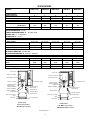
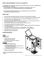
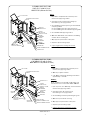
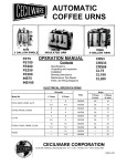
GOURMET HOT BEVERAGE DISPENSER
Models:
ICAP1
ICAP1-P
ICAP-MINI
WHIPPER
WHIPPER MINI
OPERATIONAL MANUAL
Specifications
Installation & Operating Instructions
Adjustments
Care & Maintenance
Trouble Shooting Guide
Wiring Diagram
Parts List
THIS EQUIPMENT IS TO BE INSTALLED TO COMPLY WIT H
THE APPLICABLE FEDERAL, STATE, OR LOCAL PLUMBING
CODES HAVING JURISDICTION.
IN ADDITION:
1. A QUICK DISCONNECT WAT ER CONNECTION OR
ENOUGH EXTRA COILED TUBING (AT LEAST 2X
THE DEPTH OF THE UNIT) SO THAT THE MACHINE
CAN BE MOVED FOR CLEANING UNDERNEAT H.
2. AN APPROVED BACK FLOW PREVENTION DEVICE,
SUCH AS A DOUBLE CHECK VALVE TO BE INSTALLED
BETWEEN THE MACHINE AND THE WATER SUPPLY.
Cecilware sells value...
Worldwide.
43-05 20th Avenue, Long Island City, NY 11105
FAX:
· 718-932-1414
· 718-932-7860
1
NA64A 6/99
SPECIFICATIONS
MODELS:
STORAGE CAPACITY
Hopper Capacity [lb.]
Tank Capacity [gal.]
ICAP 1 B LD
WHIPPER B
ICAP1 B LD
ICAP B LD
WHIPPER B
8
1.5
8
1.5
8
1.5
8
0 .6
8
0.6
2 (6 oz.)
60
12 (6 oz.)
2 (6 oz.)
60
12 (6 oz.)
23+1” feet
PRODUCTION CAPACITY
Continuous Draw Rate [oz/drinks/min.]
2 (6 oz.) drinks/min
2 (6 oz.) .
2 (6 oz.)
[drinks / hour]
120
120
120
Burst Capacity [oz.], drinks
28 (6 oz.)
28 (6 oz.)
28 (6 oz.)
BURST CAPACITY - Max. number of drinks dispensable with available hot water - based on 6 oz. cup.
FLOW ADJUSTMENT RATE: 1 oz./sec.
STRENGTH ADJUSTMENT RANGE: 22 - 34 gr/(6 oz.) drink
RECOVERY TIME: 10 - 18 drinks [min.]
DISPENSING RATE: [1 oz./sec.]
DIMENSIONS & CONNECTIONS
Height [inches]:
23+2.5” legs
23+2.5” legs
23+2.5” legs
23+1” feet
9
21
9
21
9
16
Width [inches]:
9
Depth [inches]:
21
CABINET MATERIAL: Powder Coated Steel
WATER INLET CONNECTION: 1/4” Male Flare
WATER PRESSURE REQUIRED: 30 -120 psi (2.1 - 8.6 kg/cm2 )
ELECTRICAL
Voltage:
Frequency:
Phase:
Max. Amps:
Heater Wattage [kw]:
110V or 220 V
60 Hz/50Hz
Single
15 A @ 115 V
1.7
110V or 220 V
110V or 220 V
60 Hz/50Hz
60 Hz/50Hz
Single
Single
15 A @ 115 V 15 A @ 115 V
1.7
1.7
TOP COVER
PRODUCT HOPPER
STEAM DEFLECTOR
STEAM DEFLECTOR
CLEANING LABEL
PRODUCT GUIDE
MIXING CHAMBER
MIXING CHAMBER
EXTENSION
DRIP TRAY HOLDER
110V or 220 V
60 Hz/50Hz
Single
15 A @ 115 V
1.5
TOP COVER
PRODUCT HOPPER
CHAMBER INSERT
(PLACE INSIDE
MIXING CHAMBER)
110V or 220 V
60 Hz/50Hz
Single
15 A @ 115 V
1.5
9
16
*Optional
CLEANING LABEL
PRODUCT GUIDE
MIXING CHAMBER
EXTENSION
MIXING CHAMBER
POWER CORD TO
FRONT PANEL
RINSE SWITCH
POWER CORD TO
FRONT PANEL
RINSE SWITCH
HEATER SWITCH
HEATER SWITCH
HEATER LIGHT
HEATER LIGHT
DRIP TRAY HOLDER
GRILL
GRILL
SUPPORT LEGS
DRIP TRAY
DRIP TRAY
FRONT VIEW
ICAP1 B LD [w/lit door]
WHIPPER B [w/o lit door]
SUPPORT LEGS
FRONT VIEW
ICAP MINI B LD [w/lit door]
MINI WHIPPER B [w/o lit door]
Illustration No. 1
2
INSTALLATION REQUIREMENTS for ICAP1 B LD and WHIPPER B:
THIS EQUIPMENT IS TO BE INSTALLED TO COMPLY WITH THE APPLICABLE FEDERAL, STATE, OR LOCAL PLUMBING CODES
HAVING JURISDICTION. IN ADDITION:
1. A QUICK DISCONNECT WATER CONNECTION OR ENOUGH EXTRA COILED TUBING (AT LEAST 2X THE
DEPTH OF THE UNIT) SO THAT THE MACHINE CAN BE MOVED FOR CLEANING UNDERNEATH.
2. AN APPROVED BACK FLOW PREVENTION DEVICE, SUCH AS A DOUBLE CHECK VALVE TO BE INSTALLED
BETWEEN THE MACHINE AND THE WATER SUPPLY.
INSTALLATION:
1.
2.
3.
4.
5.
Flush inlet water line thoroughly before connecting. If pipe sealant is necessary, teflon tape is commended.
Connect water line to the 1/4” flare fitting located at rear of the unit. A shutoff valve in the water supply line is advisable.
Check that heater switch is in the OFF position. Switch is located below DOOR ASSEMBLY lower right side corner.
Turn on water. Check water line and fittings for leaks.
Plug the power cord into a grounded 120 volt, 60 Hz 15 Amp outlet, Single use. Press and hold Rinse Button until water
flows through mixing chamber. It will take 2 to 4 minutes to fill the tank.
6. Fill hopper with DRY* powdered cocoa mix or cappuccino product. See filling instructions.
7. Turn heater switch on and allow 10 to 15 minutes for water to heat.
8. Push on Dispensing Button and check the operation of the hopper. A grinding noise will be heard if not properly engaged.
Go to Troubleshooting Guide.
9. Push on Dispensing Button and check the operation of the mixing chamber (for ICAP1 & Whipper ).
A scratching noise will be heard if whipper blade is not properly aligned. Go to Troubleshooting Guide.
10. Push Dispensing Button and check drink taste.
If adjustments are needed, see “Adjustments”.
DISPENSER OPERATION
FILLING
1. Open Front Door.
2. Lift Top Cover.
3. Fill hopper to desired level with DRY*
Powdered cocoa mix or cappuccino.
Do not overfill or pack product down when filling.
4. Close Top Cover and Door.
DISPENSING
1. Place cup under mixing chamber spout.
2. a) For Manual Units (without Timer):
Press and hold push button until cup is approximately 2/3 full.
b) For Automatic Units (with Timer):
Press and release push button. Cup will fill to size set on Timer.
3. Remove cup when flow from mixing
chamber has stopped completely.
*Moist product will clog hopper and the unit will not operate
properly.
Illustration No. 2 – (ICAP 1 B LD & WHIPPER B shown)
3
START UP INSTRUCTIONS FOR ICAP1 POUROVER CAPPUCCINO DISPENSER – see ill. 3
I. INSTALLATION INSTRUCTIONS
This equipment is to be installed to comply with the applicable Federal, State, or local plumbing codes having jurisdiction.
In addition:
1.
A quick disconnect water connection or enough extra coiled tubing (at least 2x the depth of the unit) so that the machine
can be moved for cleaning underneath.
2.
An approved back flow prevention device, such as a double check valve to be installed between the machine and the water supply.
The ICAP1 POUROVER beverage dispenser is equipped with a 3/4” Water Inlet Valve (¼" to 3/4” adapter supplied with the
unit) which is located on the right side in the back of the base (when looking at the machine from the front).
HIGHLY RECOMMENDED: A WATER SHUT-OFF VALVE and A WATER FILTER, preferably a combination Charcoal/Phosphate
Filter, to remove odors and inhibit lime and scale build up in the machine.
Note: In areas with extremely hard water, a water softener must be installed in order to prevent a malfunctioning of the equipment and in order not to void the warranty.
After the machine has been unpacked and placed on a counter, pull out the drip tray and splash guard.
It should contain the following: A Set of 4 Adjustable Leveling Legs & Water Inlet Fitting.
Connect the ¼" dia. copper waterline to the ¼" flare water inlet fitting of the valve.
Caution: Do not plug into power outlet yet. Make sure the Heater Switch is OFF (Toggle Down).
II. PRIMING - MANUAL/BOTTLE POUROVER (Toggle UP, Water Selection Switch, on the back panel)
1. Do NOT plug into power outlet yet.
2. Make sure Heater Switch is in the OFF position, located in back of machine.
3. Fill reservoir tank (top) with 2 gallons of water, wait about 3 minutes for water to fill Heating Tank below.
Refill Top Reservoir Tank with another 2 gallons of water. The unit will NOT dispense unless the Top Reservoir Tank is at
least 1/2 full. So keep Reservoir Tank full.
Note: The unit has a Float (item 3, Ill. 8) inside the Reservoir Tank, which stops the machine from dispensing
when the Reservoir Tank is low.
4. Plug into power outlet.
5. Turn Heater Switch ON.
6. Allow 10 to 15 minutes for water to reach dispense temperature of 190°F. Heater Indicator Light (red) goes ON when
heater is on (see lower front panel).
7. Fill hopper with product.
8. Place cup under dispenser.
9. Push and hold Dispense Button (green) until water flows from mixing chamber.
10. Machine is primed and ready to go.
III. PRIMING INSTRUCTIONS FOR ICAP1 POUROVER
PRIMING - AUTOFILL (Toggle Down,Water Selection Switch, on the back panel)
1. Plug into power outlet.
2. Turn Heater Switch ON.
3. Allow 10 to 15 minutes for water to reach dispense temperature of 190°F.
Heater Indicator Light (red) goes ON when heater is on (see lower front panel).
4. Fill hopper with product.
5. Place cup under dispenser.
6. Push and hold Dispense Button (green) until water flow s from mixing chamber
7. Machine is primed and ready to go.
4
IV. POUROVER-PORTABLE BOTTLE OPERATION (Toggle UP, Water Selection Switch, on the back panel)
UNIT CAN BE OPERATED WITH A 3 GALLONS CAPACITY FRESH WATER BOTTLE.
TO OPERATE WITH PORTABLE BOTTLE, proceed AS FOLLOWS:
1. Remove Reservoir Tank Cover.
2. Make sure that Reservoir Tank is only 1/2 full or empty, to prevent water splillage.
To remove excess water push dispense button.
3. Fill bottle with water .
4. Invert bottle into reservoir tank in one motion to minimize spillage.
5. Remove and refill bottle when “REFILL“ light is ON.
NOTE: REFILL LIGHT, ON THE FRONT DOOR PANEL, WILL GO ON, WHICH INDICATES THAT THE WATER TANK MUST
BE REFILLED. WHEN REFILL LIGHT GOES ON, THE UNIT WILL NOT DISPENSE UNTIL TANK IS FILLED WITH WATER.
REFILLING WITH HOT TAP WATER WILL SHORTEN HEAT UP TIME.
V. NORMAL OPERATION
(POUROVER AND AUTOREFILL)
1. Place a 6 oz. or larger cup under dispense nozzle,
then press and hold dispense switch (green) for 6
seconds.
The machine will dispense water at the rate of 1 oz.
per second. Repeat it several times to check for consistent output.
2. While the tank is heating up, remove the hopper,
load with product and reposition it back in the machine.
When Heater Light goes OFF, the tank has reached
its brew temperature and the machine is ready to
begin dispensing the first cup of Cappuccino.
VI. WATER FLOW and
DRINK STRENGTH ADJUSTMENTS
THE UNIT IS FACTORY ADJUSTED TO DISPENSE
WATER AND POWDER AT THE RATE OF 1.0 oz/
sec.
TO INCREASE OR DECREASE FLOW, PROCEED AS
FOLLOWS:
1. Remove left side panel and locate Dispense Valve
Flow Adjuster on top of Heated Tank.
2. Locate Flow Adjustment Screw (white) on Dispense
Valve.
3. Rotate Adjustment Screw Counterclockwise to INCREASE flow rate.
4. Rotate Clockwise to DECREASE flow rate.
BOTTLE
RESERVOIR
COVER
RESERVOIR
TANK
WATER FLOW
ADJUSTMENT,
SCREW ON
DISPENSE
VALVE
When making strength adjustments, do not adjust
by more than 1/4 turn at a time, without checking
drink strength (ratio of water to powder).
INDICATOR
LIGHT- RED
"REFILL TANK
WHEN ON"
DISPENSE
BUTTON
HOT WATER TANK
DRIP TRAY
5
Illustration No. 3 – ICAP 1 B LD POUROVER
DRINK STRENGTH ADJUSTMENTS
NOTE: The unit has been factory preset to deliver water at 1 oz. per second
A. TO ADJUST PRODUCT THROW (ILL # 4)
1. Open Door Assembly and remove Steam Deflector
by pulling it forward.
2. To make adjustment use a screwdriver with 1/2 inch
wide blade. Engage product adjuster as shown below
and turn as follow.
3. Turn clockwise to increase drink strength or
counter-clockwise to reduce it.
Check drink strength after every half a turn.
If after maximum adjustment, drink taste is not as
desired proceed to adjust the water flow according to
procedure B below.
4. Re-install Steam Deflector.
Illustration No. 4 – Product adjuster
B. TO ADJUST WATER FLOW RATE (ILL. # 5)
1. Remove right hand side cover of the unit.
(looking at the unit from the front)
2. Locate Flow Adjustment Key inside unit mounted
above water valve.
3. Engage Flow Adjustment Key into Flow Controller
and rotate counterclockwise to decrease
and clockwise to increase drink strength.
When making strength adjustments, do not turn
Adjustment Key more than 1/8” at a time without
checking drink strength.
4. Return Adjustment Key back into keyholder.
If after maximum adjustment, drink taste is still not
strong as desired, take auger spring out of the hopper and remove the product adjuster.
Illustration No. 5 – Water Inlet Valve
C.
1.
2.
3.
4.
DRINK SIZE ADJUSTMENT (ILL. # 6)
(AUTOMATIC UNITS - WITH TIMER)
Remove right side panel.
Turn knob on Timer right to increase or left to decrease drink size.
The number 6 on the Timer indicates approximate drink size at a
factory setting of 1 oz./sec. flow rate.
Press push button and check drink size. Repeat if
necessary, until desired drink size is dispensed.
Replace the side panel.
Illustration No 6 - Timer
6
CLEANING INSTRUCTIONS
ICAP1 B LD (with Lit Door)
WHIPPER B (without Lit Door)
DAILY:
TOP COVER
1. Wipe exterior of dispenser with a soft damp cloth.
Deflector setup by pulling forward.
CLEANING INSTRUCTIONS
NA62C
2. Disengage Product Hopper by lifting straight up,
while retaining in the upright position.
PRODUCT
HOPPER ASS'Y
STEAM
DEFLECTOR
PRODUCT SHUTE
HEATER
SWITCH
RINSE
SWITCH
GRILL
DRIP TRAY
DRIP TRAY BRACKET
3. Remove Mixing Chamber by turning Counterclockwise
and pulling forward.
A. Remove Mixing Chamber Insert by pulling up.
B. Remove Mixing Chamber Extension by pulling down.
4. Remove Mixer Blade by pulling forward.
MIXING
CHAMBER
INSERT
5. Wash Grill, Mixer Blade, Insert, Extension, and Mixing
Chamber with a mild detergent.
MIXING
CHAMBER
6. Wipe upper compartment with a damp cloth.
MIXING
CHAMBER
EXTENSION
7. Replace all parts including Hopper.
8. Dry thoroughly before reloading with product.
MIXER BLADE
MIXING CHAMBER MOUNT
SLINGER DISC
CLEANING INSTRUCTIONS
ICAP MINI B LD (with Lit Door)
MINI WHIPPER B (without Lit Door)
DAILY:
1. Wipe exterior of dispenser with a soft damp cloth.
Deflector setup by pulling forward.
TOP COVER
CLEANING INSTRUCTIONS
NB04A
2. Wash Drip Tray with hot water.
3. Flush Mixing Chamber by depressing Rinse Button
approximately 10 seconds.
HOPPER ASS'Y
STEAM
DEFLECTOR
PRODUCT GUIDE
MIXING
CHAMBER
EXTENDER
RINSE
SWITCH
MIXING
CHAMBER
WING NUT
GRILL
DRIP TRAY
DRIP TRAY BRACKET
OPTIONAL
NOTE: IN VERY HIGH VOLUME LOCATIONS, THIS
PROCEDURE SHOULD BE DONE TWICE A WEEK.
1. Open Top Cover, Door Assembly, and remove Steam
Deflector setup by pulling forward.
2. Disengage Hopper by lifting straight up,
while retaining in the upright position.
3. Remove Mixing Chamber by unscrewing wing nuts.
4. Wash all components after removing.
SEAL (GASKET)
HEATER
SWITCH
WEEKLY:
MIXING CHAMBER PLATE
MIXING CHAMBER SPACER
5. Wipe upper compartment with a damp cloth.
6. Replace all parts including Hopper.
7. Dry thoroughly before reloading with product.
Illustration No. 7
7
TROUBLESHOOTING PROCEDURE
WARNING: To reduce the risk of electrical shock unplug the dispenser power cord before repairing or replacing any
internal components of the unit. Before any attempt to replace a component be sure to check all electrical
TROUBLE
Light Display does not go on.
No power
No water when Rinse Switch
is depressed
PROBABLE CAUSE
a) Dispensing unit unplugged
b) No power from terminal block
a) Water supply off
b) Clogged inlet screen (water valve)
REMEDY
a) Reconnect dispensing unit
b) Check the terminal block for loose wire
a)Turn on water
b) Disconnect water line and clean inlet screen
No product when Dispense
Button is depressed
a) No product in hopper
b) Auger spring not working
a) Add product if auger spring is moving
b) Engage hopper to auger motor’s gear
Replace damaged coupling if needed
Check connections of motor, relay and/or
switch, if needed replace such component.
d) Clean hopper and dry thoroughly
c) Inoperative auger motor
d) Hopper outlet clogged
Water does not shut off
b) Malfunctioning Timer
c) Inoperative dispense switch
a) Clean and check all fittings of water valve.
Replace water inlet valve
b) Replace Timer (automatic units only)
c) Check switch connections. Replace dispense switch
a) Water flow too low
b) Product throw too high
a) No product in hopper
b) Product throw too low
a) Adjust water flow (see To Adjust Water Flow Rate)
b) Adjust product throw (see To Adjust Product Rate))
a) Add product
b) Adjust product throw (see To Adjust Product Rate)
Water drips from mixing
chamber
a) Temperature too high
b) Leaking inlet water valve
c) Too much water in tank’s
a) Adjust the thermostat accordingly
b) Check fittings, if needed replace water valve
c) Remove tank top and clean holes in inner
Cold drink
a) No hot water
b) Run out of hot water
c) Tank does not heat up
a) Allow tank to heat
b) Allow tank to heat after filling
c) Check for loose wire on either thermostat
or heating element. Replace either or
Drink not whipped
a) No whipper blade
b) Whipper blade stuck
a) Replace whipper blade
b) Check blade alignment, if needed replace
blade and mixing chamber
c) Replace whipper motor
Drink too strong
Drink too weak
a) Leaking inlet water valve
c) Inoperative whipper motor
Noise coming from mixing
Whipper blade not properly aligned
chamber
Light Display does not go on Defective light bulb and/or ballast.
Check blade alignment, if needed replace blade and mixing chamber
Check for loose wire or properly plugged light bulb.
Grinding noise coming from
unit
Dispenser repeats cycle.
Check the mating between the auger motor’s gear and
hopper’s coupling
a) Replace Timer (automatic units only)
Hopper not properly engaged
a) Malfunctioning Timer.
b) Malfunctioning Dispense Switch
8
DESCRIPTION AND LOCATION OF COMPONENTS
ICAP1 B LD (with lit door) & WHIPPER B (without lit door)
Illustration No. 8
9
COMPONENTS IDENTIFICATION
ITEM DESCRIPTION
P/N
ITEM
1
2
3
4
5
6
7
8
9
10
11
12
13
TANK TOP ASSY
SILICONE TUBING
DISCHARGE TUBE ASSY
DISCHARGE TUBE BRACKET
NOZZLE BRACKET
TANK BAFFLE ASSY
TANK BAFFLE SEAL
TANK CLAMP ASSY
HEATER ELEMENT 1750W 120V
WASHER, HEATER ELEMENT
NUT HEATER ELEMENT
TANK LIMIT
HI-LIMIT TEMPERATURE CONTROL
97127
77184
97122
73277
RE81A
97198
20039
97131
G0140
07059
03051
97293
59024
36
37
38
39
40
41
42
43
44
45
46
47
48
SLINGER DISC
"O" RING
MIXING CHAMBER MOUNT
MIXER BLADE
MIXING CHAMBER EXTENDER TUBE
MIXING CHAMBER
MIXING CHAMBER INSERT
LAMP HOLDER MOUNTING BRACKET (lit door)
BALLAST (for lit door only)
PRODUCT SWITCH
LAMP SOCKET - LEVITTON ( for lit door only)
FLOURESCENT LAMP 9W ( for lit door only)
DOOR WELDMENT ASSY - ICAP 1 B LD (w/lit door)
83034
?
83033
90230
77184
95001
83036
RE52A
CE221
L455C
44496
L024A
RC53Q
14
15
16
17
ELBOW, MALE 1/8 NPT X 1/4
CONTROL THERMOSTAT
TOP FRONT COVER
HOSE BARB FITTING
09246
59016
RC42C
K435C
49
50
51
52
AUGER MOTOR BRACKET
AUGER MOTOR 115V
SUPPORT PLATE F/AUGER MOTOR
GEAR AUGER DRIVE MOTOR GEAR, PLASTIC
73272
52037
90209
90208
18
19
20
21
22
K415A
95101
L477A
44242
58017
58019
B135A
B129A
RE80Q
M034C
92007
53
54
55
56
57
O RING
CARTRIDGE HEATER 20W
HEAT DUCT
PRODUCT DISPENSER ADAPTER
STEAM DEFLECTOR
20015
87024
97135
CD70C
90272
23
24
25
26
27
ADJ. VALVE ASSY #H5107 NPT
HOSE NUT
WATER VALVE INLET ASSY
POWER CORD
TIMER, OPTIONAL - (for automatic units only) 120v
TIMER, IPTIONAL - (for automatic units only) 220v
TERMINAL BLOCK SINGLE
RELAY (for automatic only) 120v
BODY FRAME WELDMENT ASSY
Legs, set 2.5" BLK
STUD DRIPTRAY
58
59
60
61
62
RESTRICTOR
RESTRICTOR RETAINER
PRODUCT ADJUSTER
AUGER SPRING
AUGER DRIVE COUPLING, PLASTIC
92173
34007
71001
95116
90211
28
29
30
31
32
DRIP TRAY PAN
GRILL
DRIP TRAY BRACKET (HOLDER )(OPTIONAL)
RINSE SWITCH
HEATER SWITCH
75060
75015
RE73A
56039
L299C
63
64
65
66
67
HOPPER & BASE ASSY
AGITATOR DRIVE GEAR
AGITATOR
PIN/STUD HOPPER
GEAR AUGER DRIVE (HOPPER BASE), PLASTIC
97098
90268
40692
04026
90210
33
34
35
HEATER INDICATOR LIGHT AMBER
WHIPPER MOTOR 115V
WHIPPER MOTOR BRACKET PLATED
C002C
52038
92177
68
69
70
RETAINER PIN, STEEL (UNDER HOPPER)
RETAINER PIN, S/STEEL (on coupling)
SIDE PANEL
04025
04030
RC40A
10
DESCRIPTION
P/N
DESCRIPTION AND LOCATION OF COMPONENTS
ICAP1 B LD POUROVER (with lit door)
% % $'
%
$&
$% $$
$#
$"
$!
$
!
$
$
#'
"
#&
#
#%
$
#$
%
&
##
#"
#!
#
#
#
"'
'
!
"&
"%
"#
"
""
#
"$
"!
"
"
$ %
& '
!
" ## $$ %%
&
''
!
!
Illustration No. 9
11
!
! !
!! !"
!" !#
!!
!# !$
!$ !%
!% !&
!& !'
!' "
"
ICAP1 B LD POUROVER (with lit door]
ITEM DESCRIPTION
P/N
ITEM DESCRIPTION
P/N
1.
2.
COLD TANK COVER ASS'Y
COLD WATER TANK WELDMENT ASS'Y
Q164A
Q163Q
37.
38.
SLINGER DISC
“O” RING
83034
?
3.
WATER LEVEL FLOAT/CONTROL SWITCH (COLD)
L499A
39.
MIXING CHAMBER MOUNT
83033
4.
5.
TANK TOP ASS'Y (FOR HOT WATER TANK)
DISPENSE (DUMP) VALVE (MULLER)
Q166Q
L467A
40.
41.
MIXER BLADE
MIXING CHAMBER EXTENDER TUBE
90230
77184
6.
7.
TANK BAFFLE ASS'Y
TANK CLAMP SEAL
97128
20039
42.
43.
MIXING CHAMBER
MIXING CHAMBER INSERT
95001
83036
8.
9.
10.
TANK CLAMP ASS'Y
HEATER ELEMENT 1750W 120V
WASHER, HEATER ELEMENT
97131
G0140
07059
44.
46.
47.
LAMP HOLDER MOUNTING BRACKET ( Lit Door )
BREW SWITCH
LAMP SOCKET - LEVITTON (for Lit Door only)
RE52C
L455A
44496
11.
12.
13.
14.
15.
16.
17.
NUT, HEATER ELEMENT
HOT WATER TANK WELDMENT ASS'Y
HI-LIMIT TEMPERATURE CONTROL
ELBOW, MALE 1/8 NPT X 1/4
CONTROL THERMOSTAT
HOSE NUT
WATER VALVE INLET ASS'Y
03051
Q165Q
59024
09246
59016
95101
L477A
48.
49.
50.
51.
52.
53.
54.
FLUORESCENT LAMP 9W (for Lit Door only)
DOOR WELDEMENT ASS'Y - ICAP1 B LD POUROVER
TOP FRONT COVER
AUGER MOTOR BRACKET
AUGER MOTOR 115V
O RING
GEAR, AUGER DRIVE MOTOR GEAR, PLASTIC
L042A
RC53Q
RC42A
73272
52037
20015
90208
18.
19.
20.
21.
23.
24.
25.
HEATER SWITCH
AUTO REFILL SWITCH
POWER CORD
LEGS, SET 2.5" BLK
RELAY (DOUBLE POLE-on at all times) 120V
TERMINAL BLOCK SINGLE
BODY FRAME WELDMENT ASS'Y
L299A
L299A
44242
M034A
L018A
B135A
RI88Q
55.
56.
57.
58.
59.
60.
61.
SUPPORT PLATE F/AUGER MOTOR
CARTRIDGE HEATER 20W
HEAT DUCT
PRODUCT DISPENSER ADAPTER
STEAM DEFLECTOR
RESTRICTOR
RESTRICTOR RETAINER
90209
87024
97135
CD70A
90272
92172
34007
26.
POWER SWITCH (TOGGLE)
L069A
62.
PRODUCT ADJUSTER
71001
27.
POWER INDICATOR LIGHT, (red)
C165A
63.
AUGER SPRING
95116
28.
GRILL
75015
64.
AUGER DRIVE COUPLING, PLASTIC
90211
29.
30.
DRIP TRAY PAN
DRIPTRAY BRACKET (HOLDER)(OPTIONAL)
75060
RE73A
65.
66.
HOPPER & BASE ASS'Y
AGITATOR DRIVE GEAR
97098
90268
31.
STUD, DRIPTRAY
92007
67.
AGITATOR
40692
32.
HEATER INDICATOR LIGHT AMBER
C002A
68.
69.
PIN/STUD HOPPER
GEAR AUGER DRIVE (HOPPER BASE), PLASTIC
04026
90210
33.
34.
35.
36.
RINSE SWITCH
INDICATOR LIGHT, GREEN "out of water/refill tank"
WHIPPER MOTOR 115V
WHIPPER MOTOR BRACKET PLATED
56039
C072A
52038
92177
70.
71.
72.
RETAINER PIN, STEEL (under Hopper)
RETAINER PIN, S/STEEL (on Coupling)
SIDE PANEL
04025
04030
RC40A
12
DESCRIPTION AND LOCATION OF COMPONENTS
ICAP MINI B LD (w/Lit Door) and MINI WHIPPER B (w/o Lit Door)
$&
$%
$$
$#
$"
$!
!
$
$
"
#
$
$
#'
%
#&
&
#%
'
#$
##
#"
#!
#
!
#
#
"
"'
"&
#
"%
"$
$
"#
%
""
&
"!
'
"
"
"
!'
!&
!%
!
"
#
$ %
' ! ! !
&
Illustration No. 10
13
!! !" !# !$
ITEM DESCRIPTION
ICAP MINI 1 B LD w/lit door) & MINI WHIPPER B (w/o lit door)
P/N ITEM DESCRIPTION
P/N
1
2
3
4
5
6
7
TANK TOP ASSY W/QC
SILICONE TUBING (HOSE)
HOSE CLAMP, METAL
CHECK VALVE, PLASTIC
TANK BAFFLE ASSY
TANK BAFFLE SEAL
TANK CLAMP ASSY
97166
77216
34034
M323A
97170
20039
97131
35
36
37
38
39
40
41
PLATE - MIX CHAMBER
SEAL - MIX CHAMBER (GASKET)
WING NUT
HOSE BARB S/S 1/4 WITH FITTING
MIXING CHAMBER
EXTENDER-MIXING CHAMBER
LAMP HOLDER MOUNTING BRACKET (for lit Door
40138
20032
03005
K436A
97169
83041
RE52A
8
9
10
11
12
HEATER ELEMENT 1500W/110V
WASHER, HEATER ELEMENT
NUT, HEATER ELEMENT
TANK
HI-LIMIT TEMPERATURE CONTROL
87037
07059
03051
97165
59010
42
43
44
45
46
BALLAST (for lit Door only) (CA33C older units
PRODUCT SWITCH
LAMP SOCKET - LEVITTON (for lit Door only)
FLOURESCENT LAMP 9W (for lit Door only)
DOOR WELDMENT ASSY - ICAP 1 B LD
CE221
L455A
44496
L042A
RC53Q
13
14
15
16
DRAIN PLUG, BRASS
CONTROL THERMOSTAT
TOP FRONT COVER
HOSE BARB FITTING
K044A
59016
RC42A
K435A
47
48
49
50
AUGER MOTOR BRACKET
AUGER MOTOR 115V
SUPPORT PLATE F/AUGER MOTOR
GEAR, AUGER DRIVE MOTOR GEAR, PLASTIC
73272
52037
90209
90208
17
18
19
20
21
ADJ. VALVE ASSY #H5107 NPT
HOSE NUT
WATER VALVE INLET ASSY
POWER CORD
TIMER (for automatic units only) 120v
K415A
95101
L477A
44242
58017
51
52
53
54
55
O RING
CARTRIDGE HEATER
HEAT DUCT
PRODUCT GUIDE (SHUTE)
STEAM DEFLECTOR
20015
87024
97167
CD70A
90272
22
23
24
B135A
RG94Q
M034A
18003
92007
75060
56
57
58
RESTRICTOR
RETAINER
PRODUCT ADJUSTER
92173
34007
71001
25
26
TERMINAL BLOCK SINGLE
BODY FRAME WELDMENT ASSY
LEGS (2.5") BLACK, PLASTIC (OPTIONAL)
RUBBER FEET 1" BLACK (W/O BRACKETS
STUD-DRIP TRAY
DRIP TRAY PAN
59
60
AUGER SPRING
AUGER DRIVE COUPLING, PLASTIC
95116
90211
27
28
29
30
31
GRILL
BRACKET-DRIP TRAY HOLDER (OPTIONAL W/2.5" LEGS ONLY)
RINSE SWITCH
HEATER SWITCH
HEATER INDICATOR LIGHT AMBER
75015
RE73A
56039
L299A
C002A
61
62
63
64
65
HOPPER & BASE ASSY
GEAR, AGITATOR DRIVE
AGITATOR
PIN (STUD) HOPPER
GEAR AUGER DRIVE (HOPPER VBASE), PLASTIC
97098
90268
40692
04026
90210
32
33
34
NUT - FOR SPACER
WASHER - FOR SPACER
SPACER - MIX CHAMBER (STUD)
03003
07007
05041
66
67
68
RETAINER PIN, STEEL, (UNDER HOPPER)
RETAINER PIN, S/STEEL, (ON COUPLING)
SIDE PANEL
04025
04030
RC75A
14
AUTOMATIC:ICAP 1 B LD
AUTOMATIC:
[LIT DOOR] & WHIPPER B [NO LIT DOOR]
ICAP 1 MINI B LD [LIT DOOR] & MINI WHIPPER B [NO LIT DOOR]
15
MANUAL
- ICAP 1 B LD [LIT DOOR]
MANUAL - ICAP 1 MINI B LD [LIT DOOR]
16
DOOR UNIT
INDICATOR LIGHT
"OUT OF WATER"
"REFILL TANK"
NOTE: TO CONVERT TO TIMER CONTROLLED DISPENSE,
CONNECT "BLUE" WIRE TO TIMER TERMINAL "L1".
CONNECT "YELLOW" WIRES TO TIMER TERMINAL "NO".
CONNECT "ORANGE" WIRES TO TIMER TERMINAL "N".
USE PIGGY BACK TERMINAL PROVIDED.
17
18